


Rinnai CHS19980HEiP, CHS1998HEiN, CHS19980HEXiN, RHS19980HEiP, RHS1998HEiN Installation Manual
...Demand Duo™ 80
Installation and Operation Manual
For Indoor Applications Only:
Commercial Applications:
CHS19980HEiP . .......... |
80 Gallon, 199,000 BTU |
CHS1998HEiN ............. |
80 Gallon, 199,000 BTU |
CHS19980HEXiN ......... |
80 Gallon, 192,000 BTU |
Residential Applications: |
|
RHS19980HEiP . .......... |
80 Gallon, 199,000 BTU |
RHS1998HEiN ............. |
80 Gallon, 199,000 BTU |
RHS19980HEXiN ......... |
80 Gallon, 192,000 BTU |
The Commercial Hybrid System is assembled with multiple and separately certified components consisting of:
•RL94i / RLX94i Tankless Water Heater
•80 Gallon Storage Tank
•Controller
READ ALL OF THE INSTRUCTIONS THOROUGHLY BEFORE INSTALLING OR OPERATING THIS SYSTEM.
(This manual is a supplement to the RL94i Installation and Operation Manual)
This manual provides information on the installation, operation, and maintenance of the water heater. For proper operation and safety, it is important to follow the instructions and adhere to the safety precautions.
A licensed professional must install the water heater according to the exact instructions in this manual.
The consumer must read the entire manual to properly operate the water heater and to have regular maintenance performed.

 WARNING
IF THE INFORMATION IN THESE INSTRUCTIONS IS NOT FOLLOWED EXACTLY, A FIRE OR EXPLOSION MAY RESULT CAUSING PROPERTY DAMAGE, PERSONAL INJURY OR DEATH.
—Do not store or use gasoline or other flammable vapors and liquids in the vicinity of this or any other appliance.
—WHAT TO DO IF YOU SMELL GAS
•Do not try to light any appliance.
•Do not touch any electrical switch; do not use any phone in your building.
•Immediately call your gas supplier from a neighbor’s phone. Follow the gas supplier’s instructions.
•If you cannot reach your gas supplier, call the fire department.
—Installation and service must be performed by a qualified installer, service agency or the gas supplier.
TABLE OF CONTENTS |
|
||
|
|
|
|
Safety Behaviors and Practices for the |
|
Piping Diagram for Basic Installations……………….… 13 |
|
Consumer and Installer………………………………….……...3 |
|
Piping Diagram for Multi-Unit Installations……….….14 |
|
|
|
|
|
Installation Instructions………………………………………...4 |
|
|
|
Installer Qualifications…………………………………....4 |
|
Direct Vent Terminal Clearances………………….……....16 |
|
|
|
|
|
Type of Installation………………………………………....4 |
|
Venting Guidelines………………………………………......….17 |
|
|
|
|
|
Installation Steps………………………………………..……4 |
|
Condensate………………………………………………........…..19 |
|
|
|
|
|
General Instructions………………………………..……….4 |
|
Final Checklist……………………………………….…...…….....20 |
|
|
|
|
|
Prepare for Installation………..………….………..…….5 |
|
Technical Data…………………………………………...…………...…21 |
|
|
|
|
|
Installation of Gas Supply……………………..………...8 |
|
Specifications………………………………………………..……...21 |
|
|
|
|
|
Connect Electricity………………………………….…….….9 |
|
Dimensions…………………………………………………..……...23 |
|
|
|
|
|
System Controller…………………………………….…. ..10 |
|
Storage Tank Maintenance………………………..…….…..24 |
|
|
|
|
|
|
|
Replacement Parts…………………………………..……...…..25 |
|
Installation of Plumbing………………………….……..11 |
|
Service/Maintenance Log…….…………..……………….....26 |
|
|
|
|
|
Typical Installations………………………….…………...12 |
|
Warranty…………………………………………..………….….....28 |
|
|
|
|
|
|
|
|
|
|
|
|
|
Important Safety Information
Safety Definitions
This is the safety alert symbol. This symbol alerts you to potential hazards that can kill or hurt you and others.
 DANGER

 WARNING

 CAUTION
Indicates an imminently hazardous situation which, if not avoided, will result in personal injury or death.
Indicates a potentially hazardous situation which, if not avoided, could result in personal injury or death.
Indicates a potentially hazardous situation which, if not avoided, could result in minor or moderate injury. It may also be used to alert against unsafe practices.
2 |
Demand Duo™ 80 |

Safety Behaviors and Practices for the Consumer and Installer

 WARNING
• Before operating, smell all around the appliance |
• Use only your hand to push in or turn the gas |
|
area for gas. Be sure to smell next to the floor |
control knob. Never use tools. If the knob will not |
|
because some gas is heavier than air and will settle |
push in or turn by hand, do not try to repair it; call a |
|
on the floor. |
licensed professional. Force or attempted repair |
|
• Keep the area around the appliance clear and free |
may result in a fire or explosion. |
|
|
||
from combustible materials, gasoline, and other |
• Do not use this appliance if any part has been under |
|
flammable vapors and liquids. |
water. Immediately call a licensed professional to |
|
• Combustible construction refers to adjacent walls |
inspect the appliance and to replace any part of the |
|
control system and any gas control which has been |
||
and ceiling and should not be confused with |
||
under water. |
||
combustible or flammable products and materials. |
||
|
||
Combustible and/or flammable products and |
• Do not use substitute materials. Use only parts |
|
materials should never be stored in the vicinity of |
certified for the appliance. |
|
this or any gas appliance. |
• Should overheating occur or the gas supply fail to |
|
|
||
• Always check the water temperature before |
shut off, turn off the manual gas control valve to |
|
entering a shower or bath. |
the appliance. |
|
• To protect yourself from harm, before performing |
• Do not adjust the DIP switch unless specifically |
|
maintenance: |
||
instructed to do so. |
||
|
||
Turn off the electrical power supply by |
• Do not use an extension cord or an adapter plug |
|
unplugging the power cord or by turning off the |
||
electricity at the circuit breaker. (The |
with this appliance. |
|
|
||
temperature controller does not control the |
• Any alteration to the appliance or its controls can |
|
electrical power.) |
be dangerous and will void the warranty. |
|
Turn off the gas at the manual gas valve, |
• Proper venting is required for the safe operation of |
|
usually located immediately below the water |
||
this appliance. |
||
heater. |
||
|
||
Turn off the incoming water supply. This can |
|
|
be done at the isolation valve immediately |
|
|
below the water heater or by turning off the |
|
|
water supply to the building. |
|

 CAUTION
•BURN HAZARD. Hot exhaust and vent may cause serious burns. Keep away from the water heater unit. Keep small children and animals away from the unit.
•Hot water outlet pipes leaving the unit can be hot to touch.

 WARNING
California law requires this notice to be provided:
California Proposition 65:
This product contains chemicals known to the state of California to cause cancer, birth defects, or other reproductive harm.
Demand Duo™ 80 |
3 |

INSTALLATION INSTRUCTIONS
(for the licensed professional)
Installer Qualifications
A licensed professional must install the appliance, inspect it, and leak test it before use. The warranty will be voided due to any improper installation.
The installer should have skills such as:
•Gas sizing.
•Connecting gas lines, water lines, valves, and electricity.
•Knowledge of applicable national, state, and local codes.
•Installing venting through a wall or roof.
•Training in installation of Rinnai water heaters. (Training can be accessed on-line at www.trainingevents.rinnai.us)
Type of Installation
• For installation in commercial applications only.
Installation Steps
Prepare for Installation ...................................... |
5 |
•Do not obstruct the flow of combustion and ventilation air. Combustion air shall not be supplied from occupied spaces.
•Do not use this appliance in an application such as a pool or spa heater that uses chemically treated water . (This appliance is suitable for filling large or whirlpool spa tubs with potable water.)
•Do not use substitute parts that are not authorized for this appliance.
 MUST DO
•The installation must conform with local codes or, in the absence of local codes, with the National Fuel Gas Code, ANSI Z223.1/NFPA 54, or the Natural Gas and Propane Installation Code, CSA B149.1.
•The appliance, when installed, must be electrically grounded in accordance with local codes or, in the absence of local codes, with the National Electrical Code, ANSI/NFPA 70, or the Canadian Electrical Code, CSA C22.1.
Determine Installation Location |
.........................6 |
Venting Guidelines ............................................. |
9 |
Installation of Plumbing ................................... |
11 |
Checklist for Plumbing ..................................... |
14 |
Installation of Gas Supply................................. |
15 |
Connect Electricity ........................................... |
16 |
Checklist for Gas and Electricity....................... |
17 |
System Controller............................................. |
17 |
Condensate ...................................................... |
18 |
Final Checklist................................................... |
20 |
General Instructions
 DO NOT
•The appliance and its appliance main gas valve must be disconnected from the gas supply piping system during any pressure testing of that system at test pressures in excess of 1/2 psi (3.5 kPa) (13.84 in W.C.).
•The appliance must be isolated from the gas supply piping system by closing its individual manual shutoff valve during any pressure testing of the gas supply piping system at test pressures equal to or less than 1/2 psi (3.5 kPa) (13.84 in W.C.).
•You must follow the installation instructions and those in Care and Maintenance for adequate combustion air intake and exhaust.
•Do not install the Commercial Hybrid System outdoors.
•Do not install the appliance in an area where water leakage of the unit or connections will result in damage to the area adjacent to the appliance or to lower floors of the structure. When such locations cannot be avoided, it is recommended that a suitable drain pan, adequately drained, be installed under the appliance. The pan must not restrict
|
combustion air flow. |
4 |
Demand Duo™ 80 |
General Instructions (Continued)
INFORMATION
•If a water heater is installed in a closed water supply system, such as one having a backflow preventer in the cold water supply line, means shall be provided to control thermal expansion. Contact the water supplier or local plumbing inspector on how to control thermal expansion.
•Should overheating occur or the gas supply fail to shut off, turn off the manual gas control valve to the appliance.
•Keep the air intake location free of chemicals, such as chlorine or bleach, that produce fumes. These fumes can damage components and reduce the life of your appliance.
EARTHQUAKE STRAPPING

 NOTICE
Product installed in the state of California must be braced, anchored, or otherwise secured to avoid motion or falling during an earthquake. Contact the California Office of the State Architect located at 1102 Q Street, Suite 5100, Sacramento, CA 95811 for instructions.
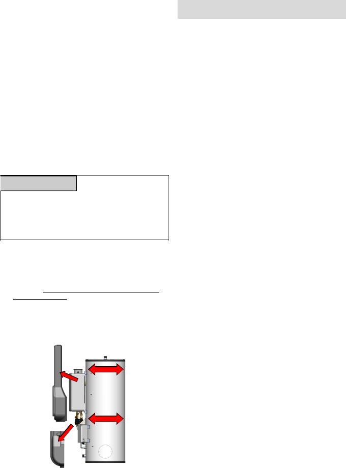
1.Loosen screws along the perimeter of the plastic enclosures
2.Remove plastic enclosures
3.Position straps around the Demand Duo tank per the requirements of California Office of the State Architect. DO NOT POSITION STRAPS OVER PIPE, FITTINGS or WIRE.
4.Replace the plastic enclosures. (Modification of the plastic enclosures may be necessary to fit the enclosures over the earthquake straps.)
5.Replace the screws around the perimeter of the plastic enclosures.
Plastic Enclosure |
|
(Side) |
STRAP |
STRAP
Plastic Enclosure
(Bottom)
Prepare for Installation
Parts included:
•Commercial Hybrid System
•Temperature and Pressure Relief Valve (Tank)
•Pressure Relief Valve (Pre-installed on Tankless)
Tools needed:
• Pipe wrenches (2) |
• Gloves |
• Adjustable pliers |
• Safety glasses |
• Screwdrivers (2) |
• Level |
• Wire cutters |
|
Tools that might be needed: |
|
• Hammer drill with |
• Core drill with diamond |
concrete bits |
head |
• Saw |
• Torch set |
• Threading machine with |
• Copper tubing cutter |
heads and oiler |
• Steel pipe cutter |
|
|
Materials needed: |
|
• Soap or gas leak |
• Teflon tape |
detector solution |
(recommended) or pipe |
• Approved venting |
compound |
|
|
|
• Pipe insulation |
Materials that may be needed: |
|
• Heat tape |
• Single gang electrical |
• Electrical wire and |
box |
|
|
conduit per local code |
• Wire nuts |
• PVC glue/cement |
• Unions and drain valves |
• 5/8” ID PVC flexible |
• Drain Pan |
tubing |
• Earthquake Strap |
|
|
• 2 conductor 22 AWG |
|
wire for controller |
|
Demand Duo™ 80 |
5 |
Determine Installation Location
You must ensure that clearances will be met and that the vent length will be within required limits. Consider the installation environment, water quality, and need for freeze protection. Requirements for the gas line, water lines, electrical connection, and condensate disposal can be found in their respective installation sections of this manual.
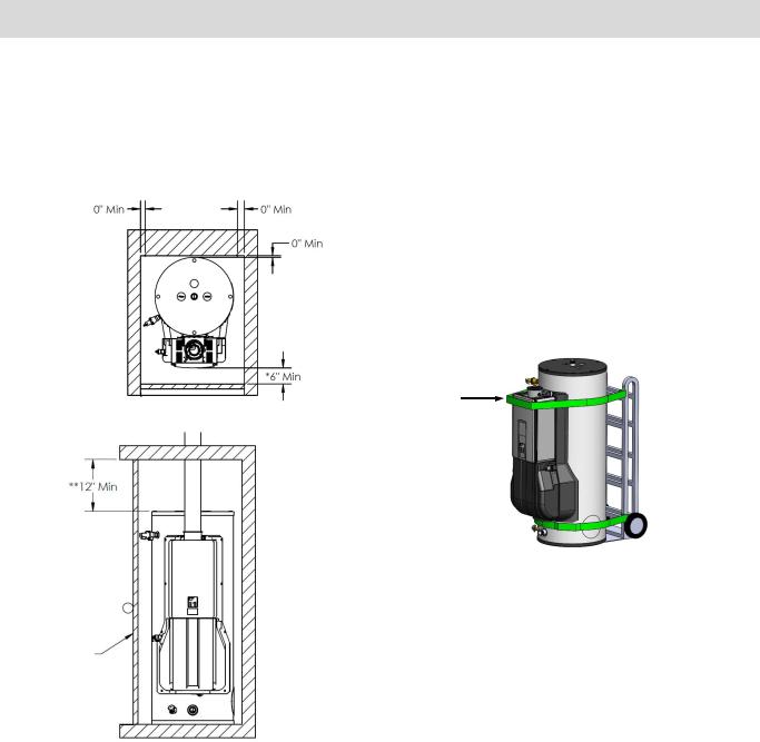
•Choose the right hand truck to support the weight and size of the water heater. Refer to the “Specifications” section in this manual for specific weights and dimensions.
•Use proper lifting techniques to load the water heater onto the hand truck:
•Position the water heater onto the hand truck so the weight is evenly balanced and the tank is touching the rails of the hand truck.
•Secure the water heater to the hand truck:
Position STRAP A around the tankless unit as illustrated below.
Position STRAP B around the base of the tank below the LOWER ENCLOSURE.
Strap A
Lower
Enclosure
Strap B 
Door
Minimum Clearances
The minimum clearances from both combustibles and non-combustibles construction is:
•0 inches from the sides
•0 inches from the back
•12 inches from the top
•6 inches from the front
•0 inches from vent components and condensate drain line.
*The clearance for servicing is 24 inches in front of the water heater.
**The clearance for servicing the anode rods is 54 inches from the top of the water heater.
Checklist to Determine Installation Location
□The water heater is not exposed to corrosive compounds in the air.
□The water heater location complies with the clearances.
□For indoor models, the planned venting will not
exceed the maximum length for the number of elbows used.
□The planned venting termination/air intake location meets the clearances.
□Indoor air is not being used for combustion.
□The water supply does not contain chemicals or
exceed total hardness that will damage the heat exchanger.
□The installation must conform with local codes or,
in the absence of local codes, with the National Fuel Gas Code, ANSI Z223.1/NFPA 54, or the Natural Gas and Propane Installation Code, CSA B149.1.
□Leave the entire manual taped to the water
6 |
Demand Duo™ 80 |
REFER TO THE RL94 MANUAL FOR SPECIFIC DETAILS ON:
•Approved Vent Manufacturers and Terminations
•Termination Clearances
•Maximum Vent Length
•Flue Installation with Concentric Venting
•Consumer Operation Guidelines for the Safe Operation of your Water Heater
•How to use the RL94 Temperature Controller
•RL94 Diagnostic Codes
•RL94 Required Maintenance (Draining of the tankless water heater will
require the lower enclosure to be removed. Reference page 17 to remove the enclosure.)
•RL94 Replacement Parts
Demand Duo™ 80 |
7 |
Installation of Gas Supply

 WARNING
1.If you are not knowledgeable or qualified to install gas lines or connections, then contact a licensed professional to install the gas supply.
2.Turn off 120v power supply.
3.Turn off the gas.
4.Gas is flammable. Do not smoke or provide other ignition sources while working with gas.
5.Do not turn on the water heater or gas until all fumes are gone.
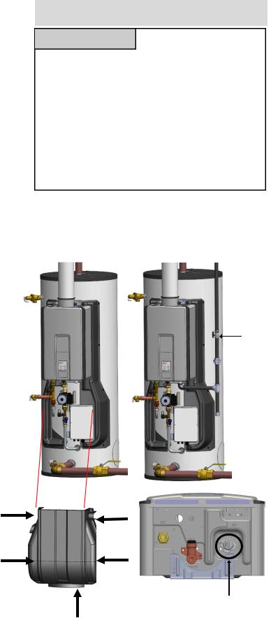
General Instructions
In order to access the gas connections, remove the plastic rivet screws that attach the lower enclosure to the assembly. Proceed to then remove the lower enclosure.
Gas
Valve
 Union
Union
|
Gas Connection |
Lower Enclosure |
(3/4” MNPT) |
|
REFER TO THE RL94 MANUAL FOR SPECIFIC DETAILS ON SIZING THE GAS PIPE.
 MUST DO
•A manual gas valve must be placed in the gas supply line to the water heater. Install a union between the gas valve and the appliance for future servicing or unit removal.
•Check the type of gas and the gas inlet pressure before connecting the water heater. If the water heater is not of the gas type that the building is supplied with, DO NOT connect the water heater. Contact the dealer for the proper unit to match the gas type.
•Check the gas supply pressure immediately upstream at a location provided by the gas company. Supplied gas pressure must be within the limits shown in the Specifications section with all gas appliances operating.
•Before placing the appliance in operation all joints including the heater must be checked for gas tightness by means of leak detector solution, soap and water, or an equivalent nonflammable solution, as applicable. (Since some leak test solutions, including soap and water, may cause corrosion or stress cracking, the piping shall be rinsed with water after testing, unless it has been determined that the leak test solution is noncorrosive.)
•Use approved connectors to connect the unit to the gas line. Purge the gas line of any debris before connection to the water heater.
•Any compound used on the threaded joint of the gas piping shall be a type which resists the action of liquefied petroleum gas (propane/LPG).
•The gas supply line shall be gas tight, sized, and so installed as to provide a supply of gas sufficient to meet the maximum demand of the heater and all other gas consuming appliances at the location without loss of pressure.
•Always check all gas pipe connections and fittings for leaks before operating the water heater. Use soapy water on all fitting and visually inspect for bubble formation. Rinse off soapy water and wipe dry.
8 |
Demand Duo™ 80 |

Connect Electricity

 WARNING
Do not use an extension cord or an adapter plug with this appliance.
The water heating system must be electrically grounded in accordance with local codes and ordinances or, in the absence of local codes, in accordance with the National Electrical Code, ANSI/ NFPA No. 70.
The tankless water heater is equipped with a threeprong (grounding) plug for your protection against shock hazard and should be plugged directly into the three-prong receptacle located at the bottom of the controller.
Do not rely on the gas or water piping to ground the water heater. A terminal block inside the controller should be used for the grounding connection.
The water heater requires 120 VAC, 60 Hz power from a properly grounded circuit.
The wiring diagram is located on the Technical Sheet attached to the inside of the front cover.
Terminal
Block
Low Voltage Ther-
mistors
Pump Control
Output: 120 Volt
Supply Power
Input: 120 Volt
(3 Prong Plug)
Power Supply
Tankless Supply
Output: 120 Volt (3 Prong Receptacle already connected to tankless from factory)
REFER TO THE RL94 MANUAL FOR :
•High Altitude Adjustment
•Vent Length Adjustment
•Temperature Controller Installation
Green |
White |
Black |
Green |
White |
Black |
Green |
White |
Black |
PRE-WIRED PUMP |
PRE-WIRED |
CONNECTION |
SUPPLY POWER |

 ATTENTION
DO NOT connect power to the commercial hybrid system prior to completing installation and the system has been filled with water.
Do not rely on the gas or water piping to ground the water heater. A terminal block inside the controller should be used for the grounding connection.
The water heater requires 120 VAC, 60 Hz power from a properly grounded circuit.
The wiring diagram is located on the Technical Sheet attached to the inside of the front cover.
Demand Duo™ 80 |
9 |

SYSTEM CONTROLLER
The system controller maintains communication between the tank and tankless to effectively control the tank temperature based on the selected temperature on the tankless unit.
By reading the tank temperature (J22) and tankless outlet temperature (J2), the System Controller will energize (120V) the pump when the tank temperature drops. When the tank temperature returns to the selected set temperature the System Controller will de-energize the pump and remain in standby until the tank temperature drops again.

 ATTENTION
When power is supplied, the System Controller will maintain pump operation. If system is not in use for an extended period of time, Disconnect power from the system.
Checklist for Gas and Electricity
□A manual gas control valve is placed in the gas line to the water heater.
□Check the gas lines and connections for leaks.
□Confirm that the gas inlet pressure is within limits.
□Confirm that the water heater is rated for the gas type supplied.
□Confirm that the electricity is supplied from 120 VAC, 60 Hz power source and is in a properly grounded circuit.
□Confirm that an extension cord or an adapter plug has NOT been used with the water heater.
CONTROLLER DIAGNOSTICS
PUMP ON (SOLID GREEN LIGHT)
PUMP OFF (NO LIGHT)
NORMAL OPERATION (SLOW PULSE)
THERMISTOR ERROR (RAPID PULSE)
10 |
Demand Duo™ 80 |
 Loading...