


RHFE-1004FA

WARNING
IMPROPER INSTALLATION, ADJUSTMENT, ALTERATION,
SERVICE OR MAINTENANCE CAN CAUSE PROPERTY
DAMAGE, PERSONAL INJURY OR LOSS OF LIFE, REFER
TO THE OWNER'S INFORMATION MANUAL PROVIDED
WITH THIS APPLIANCE. INSTALLATION AND SERVICE
MUST BE PERFORMED BY A QUALIFIED INSTALLER,
SERVICE AGENCY OR THE GAS SUPPLIER.
ENERGYSAVER RHFE-1004FA
Operation Manual
Table of Contents
Page
FEATURES OF THE RHFE-1004FA UNITS ..........................................................1
SAFETY DEVICES ................................................................................................1
IMPORTANT POINTS / USAGE AND INSTALLATION MUSTS ............................3
DIMENSIONS ........................................................................................................5
SPECIFICATIONS .................................................................................................6
SAFETY POINTS ..................................................................................................8
GETTING TO KNOW YOUR NEW RHFE-1004FA ................................................10
CONTROL PANEL .................................................................................................11
CUT-AWAY DIAGRAM ...........................................................................................12
NOTICE BEFORE INSTALLATION .......................................................................13
INSTALLATION INSTRUCTIONS ..........................................................................14
GAS CONNECTION ..............................................................................................15
VENT TERMINATION CLEARANCES ..................................................................16
LOCATION / CLEARANCES .................................................................................17
SLEEVE AND MANIFOLD INSTALLATION ...........................................................19
FITTING UNIT .......................................................................................................21
OPERATING INSTRUCTION LABEL ....................................................................23
ADDITIONAL CUSTOMER OPERATING INFORMATION ....................................24
TESTING ...............................................................................................................30
CHECK ..................................................................................................................30
PRE-SERVICE CHECK .........................................................................................31
TROUBLE SHOOTING ..........................................................................................32
ERROR MESSAGES..............................................................................................33
MAINTENANCE / SERVICE ..................................................................................34
WIRING DIAGRAM ................................................................................................35
WARRANTY INFORMATION .................................................................................36
SCHEMATIC DIAGRAM ........................................................................................38
PARTS LIST ...........................................................................................................45
RHFE-1004FA FLOW DIAGRAM ..........................................................................50
EXTENDED FLUE PIPE KIT .................................................................................51
TECHNICAL DATA ................................................................................................56
FEATURES OF THE RHFE-1004FA UNITS
– 1 –
SAFETY DEVICES
◆ Clean Heating Forced Flue Type
◆ Easy Operation One-Touch Ignition
◆ Sensible Temperature Control Feature
◆ Comfortable Room Temperature Control and Display
◆ Warm Air Outlet at Floor Level (Keeps Your Feet Warm)
◆ Child Safety Lock
◆ Room Temperature Setting Memory
◆ Dirty Air Filter Indicator Lamp
◆ Energy-Saving Economy Setting
◆ Humidifier Tray
◆ Air Flow Directional Louvers
◆ Direct Vent Easily Installed
◆ Proportional Heating Variable Capacity
◆ Hush! Quiet Operation
◆ Modern Design Minimizes Floor Space Requirements
◆ Failure Message Display
Spark Safety Device: Automatically shuts unit down when there is an abnormal spark at time
of ignition.
Flame Failure Device: Activated when burner flame fails. This prevents raw gas from being
released.
Overheat Switch: This device automatically cuts the gas off if the heater exceeds a
predetermined temperature. This is normally caused by an
obstruction in front of the louvers, or a blocked fan filter.
Two Fusible Links: Backs up the overheat switch. If the fusible link cuts the unit off, a
service call by an authorized person is required to replace the link.
– 2 –
Overcurrent Prevention Device: This is a 5 amp. glass fuse found on P.C. board. Design to
shut unit down in case of overcurrent. If fuse blows all
indicator lamps will be “OFF”.
Power Outage Safety Device: This safety device cuts off gas passage and stops
operation.
Local and state codes must be adhered to prior to installation.
Rinnai is continually updating and improving products therefore specifications are subject to change
without prior notice.
Thank you for purchasing a Rinnai gas forced flue heater.
Before using this product, please read this manual carefully to insure proper use of the product.
Please read the attached warranty thoroughly and keep it in a safe place.
GENERAL
INFORMATION
THIS SERIES HEATER IS DESIGN CERTIFIED BY CSA
INTERNATIONAL AS A DIRECT VENT WALL FURNACE AND
MUST BE INSTALLED ACCORDING TO THESE INSTRUCTIONS.
ALTERATION OF THE ORIGINAL DESIGN INSTALLED OTHER
THAN AS SHOWN IN THESE INSTRUCTIONS OR USED WITH
A TYPE OF GAS NOT SHOWN ON THE RATING PLATE, IS THE
RESPONSIBILITY OF THE PERSON AND COMPANY MARKING
THE CHANGE.
※See conversion for setting gas pressures.
*There's 1/8" NPT pipe tap provided for gas pressure test. That is located on the gas control assembly A.
The minimum inlet gas supply pressure is for the purpose of input adjustment.
Minimum supply gas pressure
Maximum supply gas pressure
Manifold test pressure
NAT.
5.0" (127mmH2O)
10.5" (267mmH2O)
Factory set
LPG
11.0" (279mmH2O)
13.0" (330mmH2O)
Factory set
IMPORTANT POINTS / USAGE AND INSTALLATION MUSTS
– 3 –
Unpack heater and check for damage. (DO NOT INSTALL DAMAGED HEATER.) If heater is
damaged, contact your supplier for advice. Before installing a heater, check the label for the correct gas
type (see label on heater). Refer to local gas authority for confirmation of gas type if you are in doubt.
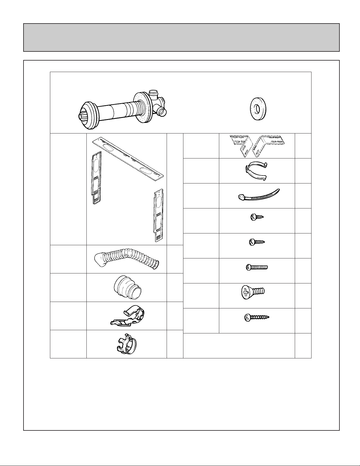
Included in Carton:
Customers Operating Information
IMPORTANT
Before using this product, please read this manual carefully to insure proper use of product.
1. The installation must conform with local codes or, in absence of local codes, the National Fuel Gas
Code, ANSI Z223.1 or the Canadian Installation Code, CAN/CGA-B149.
2. For information on gas type, see data plate on the appliance.
3. This heater must not be installed where curtains or other combustible materials could come into
contact with it. In some cases curtains may need restraining.
4. This appliance is not designed to be built in.
5. If you move, check the gas type in the area where you are moving to. The local gas authority will be
able to advise on local regulations.
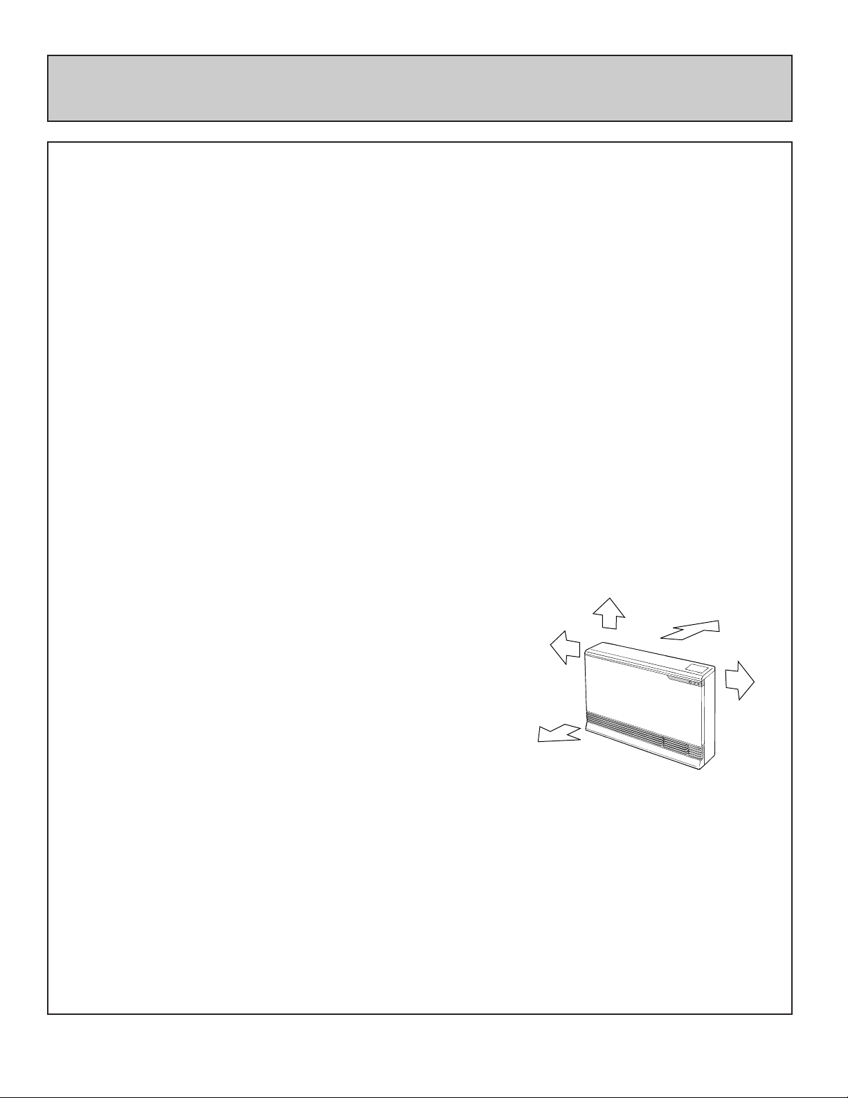
6. This heater discharges a large volume of warm air at low level to provide even heat distribution. If
the air in the room contains cooking vapor or cigarette smoke, and the heater is used on a carpet,
the surface of the carpet may become discolored. In addition, some nylon carpets contain dyes
which may be affected by the warm air flow. Some soft vinyl surfaces are also subject to distortion,
or discoloration by warm air. To prevent discoloration of carpets, etc., a mat should be placed under
the appliance, extending about 30" (750mm) in front of it.
Diagram shows minimum
clearances from combustible
materials.
Rinnai recommends 10 inches (250mm) clearance on both sides
for future servicing.
7. Read these rules and the instructions carefully. Check all local codes. Failure to follow these could
cause a malfunction of the heater resulting in death, serious bodily injury and/or property damage.
8. This appliance is only for use with the type of gas indicated on the rating plate. This appliance is not
convertible for use with other gases, unless a certified kit is used.
If a conversion of the unit is needed, conversions must be performed at Rinnai America or
anthorized agent at owner's expense.
9. WARNING: Any change to this heater or its controls can be dangerous.
10. If a gas leak is suspected, turn heater off, turn gas supply valve off at appliance connector valve.
Open windows to ventilate area immediately and contact your dealer or gas company.
11. DO NOT PLACE CLOTHING OR FLAMMABLE MATERIALS, GASOLINE AND OTHER
FLAMMABLE VAPORS AND LIQUIDS, ON OR NEAR THE HEATER.
10"(250mm)
0"
2"
(50mm)
2"
(50mm)
40" (1m)

– 4 –
12. YOUNG CHILDREN SHOULD BE CAREFULLY SUPERVISED WHEN THEY ARE IN THE SAME
ROOM WITH THE HEATER.
13. LPG containers must not be installed indoors.
14. Do not use this room heater if any part has been under water. Immediately call a qualified service
technician to inspect the room heater and to replace any part of the control system and any gas
control which has been under water.
15. Adequate clearances for accessibility for purposes of servicing and proper operation should be
provided.
16. Adequate clearances around air openings should be provided.
17. Do not install in areas where curtains, drapes, clothing, or other moving flammables are within 12
inches of this unit.
18. Periodic examination of the venting system is required.
19. The flow of combustion and ventilation air should not be obstructed.
20. A manufactured Home (Mobile Home) installation must conform with the Manufactured Home
Construction and Safety Standard, title 24CFR, Part 3280, or, when such a standard is not
applicable, the Standard for Manufactured Home Installations, ANSI A225.1 or Standard for Gas
Equipped Recreational Vehicles and Mobile Housing, CSA Z240.4.
21. "This appliance must be installed in accordance with the current standard CSA Z240.4 GAS
EQUIPPED RECREATIONAL VEHICLES AND MOBILE HOUSING. Cet appareil doit ette installe
conformement aux, exigences de la norme Z240.4 en vigeuer de l’ACNOR, Installations de gaz dans
les constructions mobiles et vehicules recreatifs."
22. If a blockage occurs at the vent terminal due to snow, ice, leaves, spider webs or other type of
obstructions the unit will stop working. The unit will not function until the blockage has been
removed. If the unit then fails to operate contact a qualified service agency.
23. For manufactured (mobile) home or residential installation, this unit has been designed and certified
to be converted from natural gas to propane or vice-versa. When provisions are being made to
convert this unit, a certified conversion kit must be used. You must also readjust manifold gas
pressure to specifications indicated in the conversion manual. If in doubt contact Rinnai America for
assistance.
24. Clothing or other flammable material should not be placed on or near the appliance.
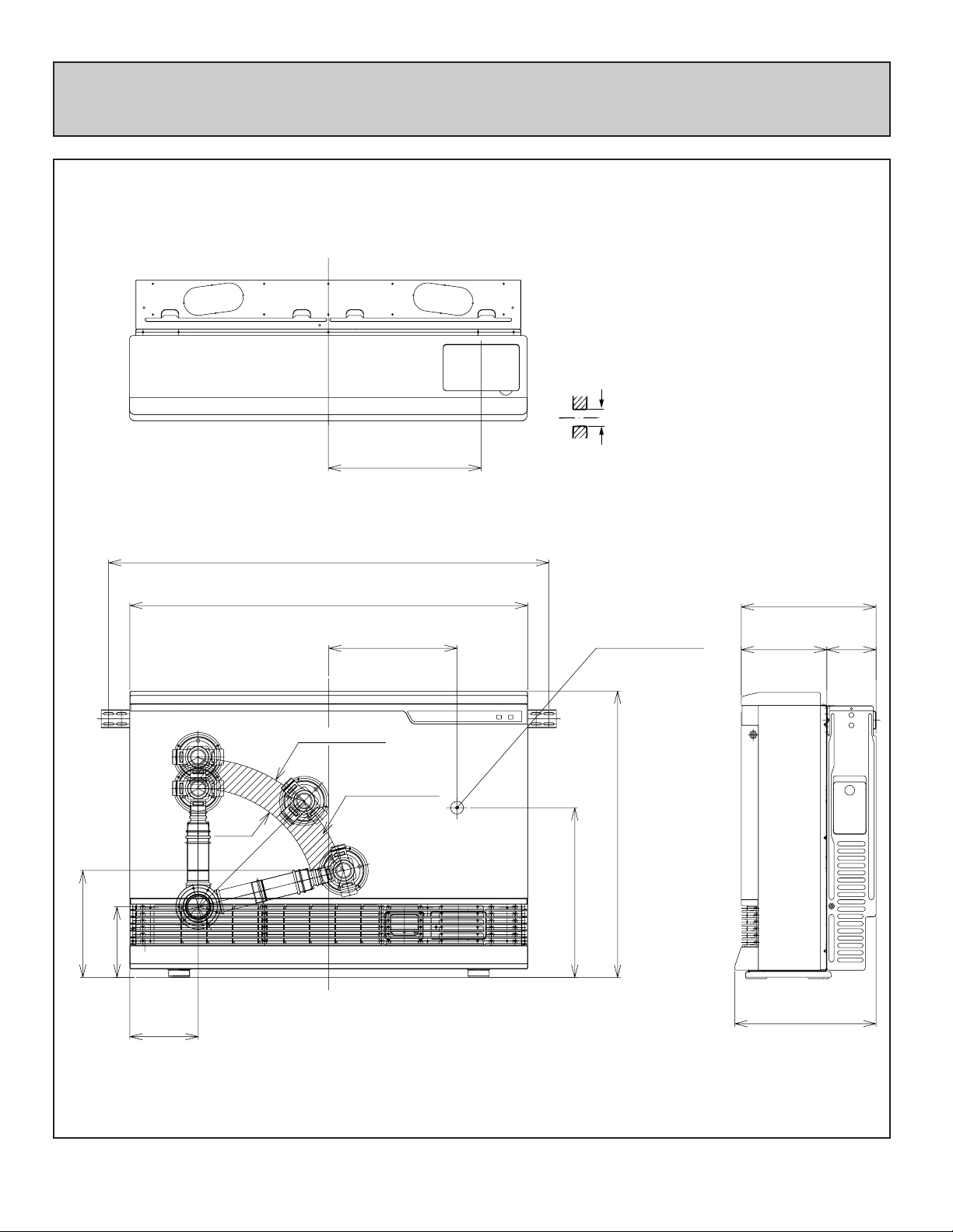
DIMENSIONS
– 5 –
14 1/16" (357.5)
12 3/8" (315)
13" (330)
7 7/8" (200)
4 1/2" (115)
36 5/8" (930)
40 1/2" (1029)
26 3/8" (670)
15 5/8" (397)
11 13/16" (300)
GAS CONNECTION
10 7/8"
(R277)
9 13/16" (250)
6 1/2" (165)
6 5/16"(160)
13 3/4" (R350)
Cavity Opening
FLUE MANIFOLD POSITION
Center of hole for flue manifold can be drilled
anywhere within the shaded area. (To avoid
studs, etc.)
FOR WEATHERBOARD WALLS DRILL
THROUGH CENTER OF WEATHER BOARD
FROM OUTSIDE, THEN DRILL FROM
INSIDE THROUGH PLASTERBOARD.
Before drilling the flue hole, check for water
and gas pipes as well as electric cables. Use
a 3 1/8" (80mm) drill for hole through wall.
Flue Hole
3 1/8"
(80mm)
inches (mm)
SPECIFICATIONS
– 6 –
MODEL #
RHFE-1004FA-P
PROPANE
BTU/h MIN. CLEARANCES
INPUT
OUTPUT
SIDE
TOP
LO:203.4
HI:360.6
LO:203.4
HI:360.5
FRONT
2
"
(50mm)
10"
(250mm)
40"
(1m)
40"
(1m)
FAN CFM
OUTPUT
10"
(250mm)
2"
(50mm)
Low
10,500
High
38,400
Low
8,400
High
30,700
Low
8,400
High
29,200
Low
10,500
High
36,500
SPECIFICATIONS
Type of Appliance Fan forced flued gas furnace
Model RHFE-1004FA ENERGYSAVER
Width−36 5/8" (930mm)
Dimensions Depth−12 3/8" with back spacer (315mm with back spacer)
Height−26 3/8" (670mm)
Weight Approx. 90 lbs.
Connections
Electrical−AC 120V 60Hz 121 watts
Gas−1/2" female NPT
Combustion System Stainless steel bunsen burner
Ignition System Continuous spark
Operation Finger touch control buttons
Temperature Control
Electronic thermostat HI-LOW/OFF
Up/down switch 2°F increments
Temperature Range
Modulates Continuous
LOW=55°F 60°F〜80°F HI=High Combustion
Warm Air Outlet Bottom front louver
Indicator/Lamps Operation/Combustion, Filter, SetTemp., RoomTemp., Economy, Function Lock.
Operating Buttons ON/OFF, Up/down, Function-lock, Economy
Economy Mode Energy saving feature
Humidifier Tray Capacity−7 pints (3000cc)
RHFE-1004FA-N
NATURAL
– 7 –
Safety Devices
Noise Level Range
HI〜LOW=47〜37dB(A)
TYPE
SPECIFICATIONS FOR VENT SIZES
S Thin Walls Mobile Home
Wood Walls
Wood/Brick
Brick/Block
Special
3
"−4 1/2"
(75−115)mm
4 1/2"−9 1/2"
(115−240 )mm
9 1/2"−15 3/4"
(240−400 )mm
15 3/4"−23 5/8"
(400−600 )mm
23 5/8"−31 1/2"
(600−800 )mm
A
B
C
D
3 1/8" (80mm)
13ft., 2 bends (4m, 2 bends)
Combustion Method
Air Supply Exhaust
Radiation Method
Forced combustion
Closed Type
Forced convection
Wall Penetration
Hole
Max. Extended
AIR SUPPLY/
EXHAUST PIPE
Flame failure – Flame rod
Over heat – Bi-metal switch, thermal fuse, thermistor
Power failure – PCB
Power surge – 5 Amp. fuse
Fan delay – Micro computer timer
Pre-purge – Combustion fan, pre-purge timer, spark sensor
Room over heat – Automatic cut off at 104°F after 10 minutes
** BTU - Efficiency increase with vent size. Clearances from combustibles see page 3.
** Thermal efficiency rating determined under continuous operating conditions, and was determined
independently of any installed system.
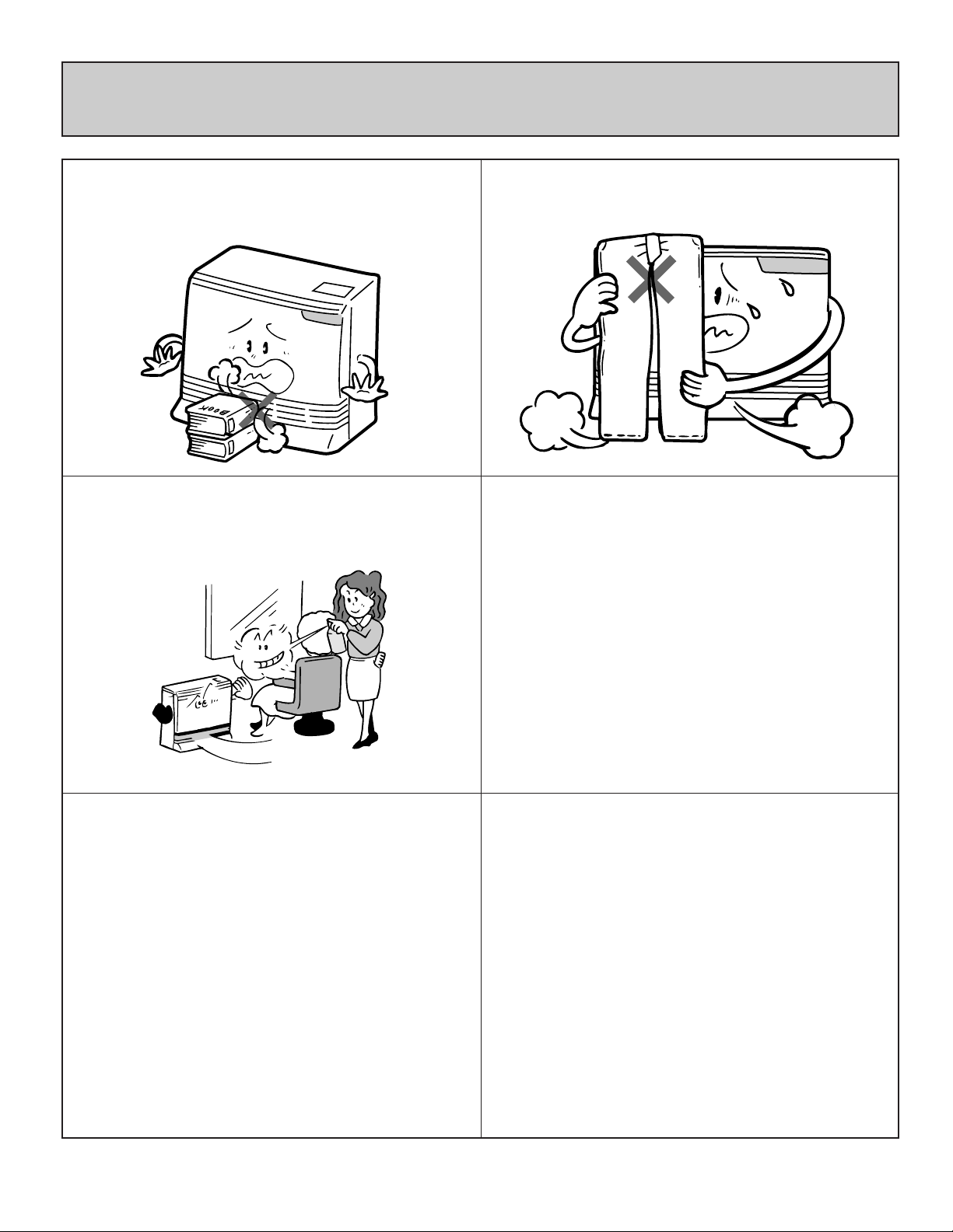
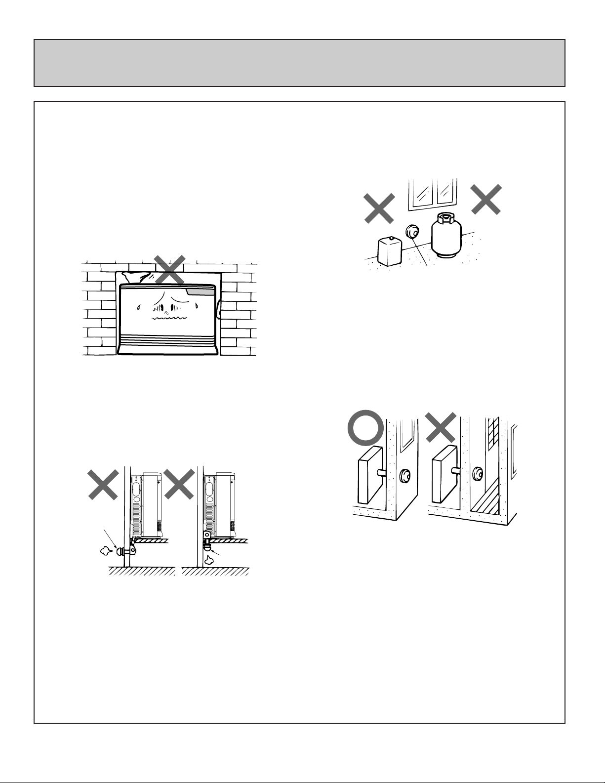
SAFETY POINTS
– 8 –
Do not restrict the warm air discharge by
placing articles in front of the heater.
This appliance must not be used for any
purpose other than heating.
Do not install the heater in an unusually
dusty area.
Do not allow anyone to sit on or lean against
the appliance.
Do not spray aerosols while the heater is
operating. Most aerosols contain butane
gas, and can be a fire hazard if used near
this heater when it is in use.
Do not allow curtains or other flammable or
combustible materials to come into contact
with the heater.
Combustible materials must not be placed
where the heater could ignite them.
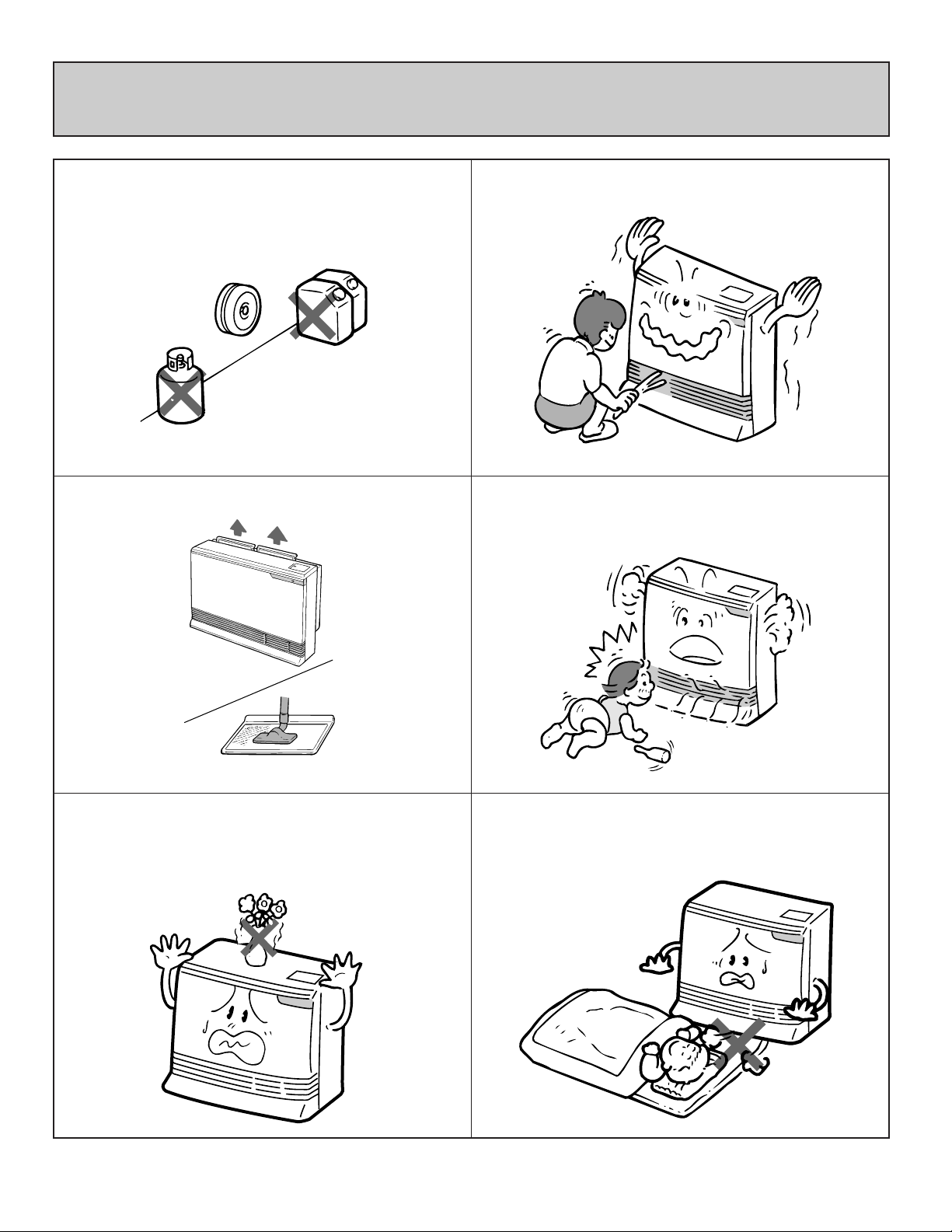
SAFETY POINTS
– 9 –
Keep flammable materials, trees, shrubs,
etc., away from the flue terminal.
Young children should be supervised at all
times. Hand or body contact with the
louvers should be avoided.
Do not allow young children or an infant to
sleep directly in front of the heater.
Filter should be cleaned at regular intervals.
See page 29.
Do not place articles containing liquids on
top of the heater. Liquid spilled on the
controls may cause extensive damage.
Clean as needed.
LPGAS
GAS
Gasoline
Do not allow anyone to poke articles
through the louvers.
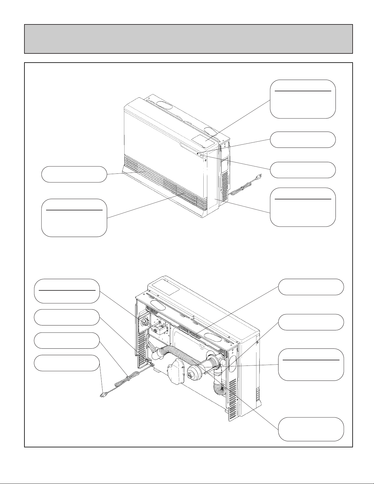
GETTING TO KNOW YOUR NEW RHFE-1004FA
– 10 –
CONTROL PANEL
OPERATION/TEMPE
RATURE
CONTROL DISPLAY
OPERATION LAMP
RATING PLATE
MODEL NUMBER,
SERIAL NUMBER,
GAS TYPE, ETC.
WARM AIR OUTLET
HUMIDIFIER
OPEN THE DOOR
AND POUR WATER
INTO THE TRAY.
VENT TERMINAL
COMBUSTION/
EXHAUST
COMBUSTION AIR
INTAKE HOSE
EXHAUST PIPE
AIR FILTER
THERMISTOR
GAS CONNECTION
1/2" NPT
POWER CORD
PLUG 120V AC
FILTER LAMP
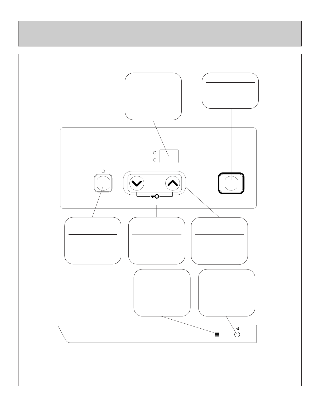
CONTROL PANEL
– 11 –
SetTemp
RoomTemp
Economy
Temp
Control
FunctionLock
Filter
ON/OFF
ON
FUNCTION
LOCK
Lamp is "green"
when this feature
is on.
FILTER LAMP
Flashes when filter
is dirty.
OPERATION LAMP
This lamp turns
"green" when power
is on. Lamp will
change to "red"
when burner is on.
TEMPERATURE
BUTTONS
""adjust temp. to
lower setting.
""adjust temp. to
a higher setting.
ENERGY SAVING
BUTTON
Lamp is "green"
when this feature is
activated.
ALL BUTTONS BEEP WHEN OPERATED.
〈CONTROL PANEL〉
〈INDICATOR DISPLAY〉
>
>
TEMPERATURE
DISPLAY
SHOWS EITHER THE
TEMPERATURE OR
CODED ERROR
MESSAGES.
ON/OFF BUTTON
Easy operation
One touch ignition
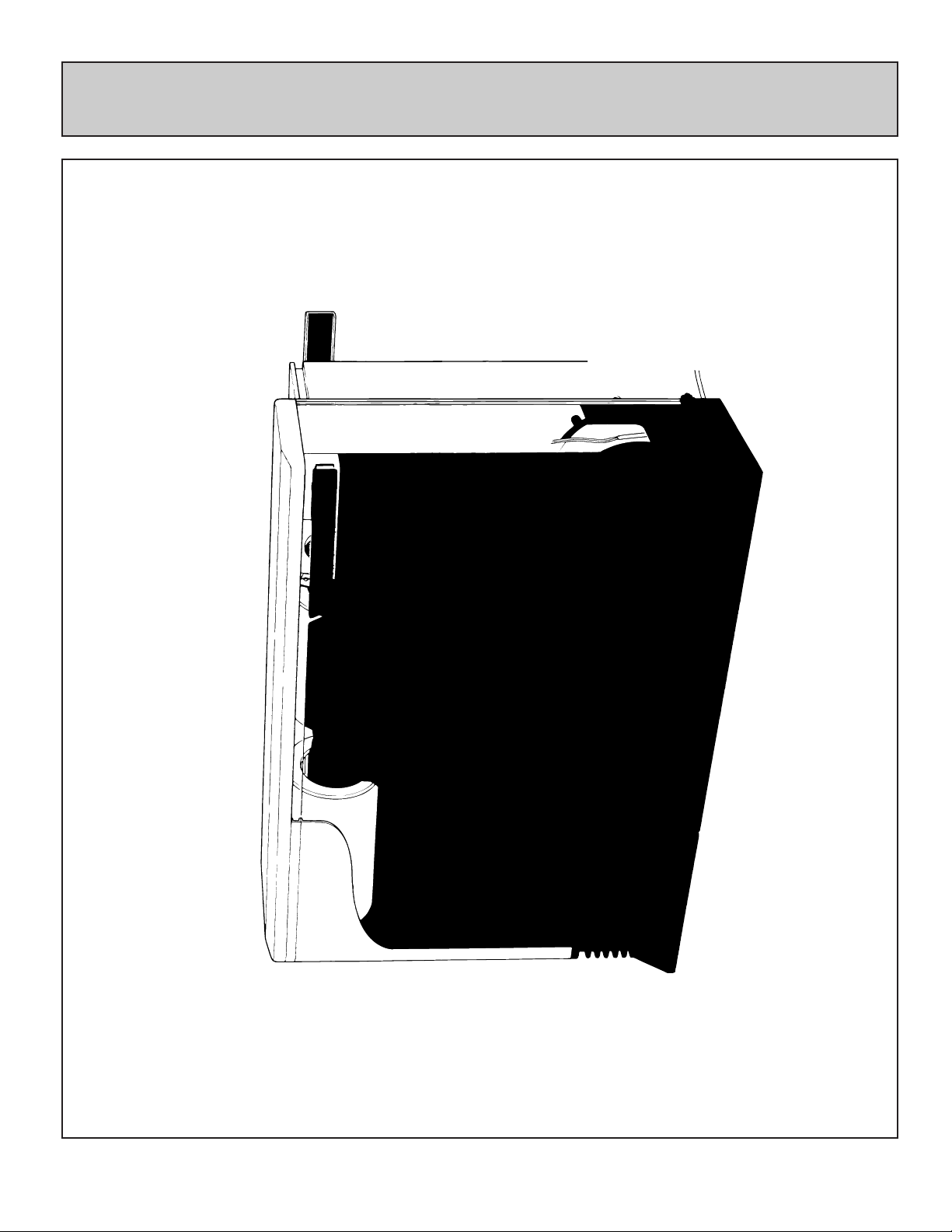
CUT-AWAY DIAGRAM
– 12 –
1004FA-8

NOTICE BEFORE INSTALLATION
– 13 –
The heater must be installed by a qualified service
person according to these installation instruction.
Check your local building codes for the proper method
of installation. In the case of absence of local codes,
this heater should be installed in accordance with the
National Fuel Gas Code ANSI Z223.1.
Check local codes or, in the absence of local codes,
the current CAN/CGA B149 INSTALLATION CODE.
DUE TO HIGH TEMPERATURES, THE
APPLIANCE SHOULD BE LOCATED OUT OF
TRAFFIC AND AWAY FROM FURNITURE AND
DRAPERIES.
CHILDREN AND ADULTS SHOULD BE ALERTED
TO THE HAZARDS OF HIGH SURFACE
TEMPERATURES AND SHOULD STAY AWAY TO
AVOID BURNS OR CLOTHING IGNITION.
“WARNING” Do not operate appliance with the
panel(s) removed, cracked or broken. Replacement
of the panel(s) should be done by a licensed or
qualified service person.
INSTALLATION AND REPAIR SHOULD BE DONE
BY A QUALIFIED SERVICE PERSON. THE
APPLIANCE SHOULD BE INSPECTED BEFORE
USE AND AT LEAST ANNUALLY BY A QUALIFIED
SERVICE PERSON. MORE FREQUENT
CLEANING MAY BE REQUIRED DUE TO
EXCESSIVE LINT FROM CARPETING, BEDDING
MATERIAL, ETC. IT IS IMPERATIVE THAT
CONTROL COMPARTMENTS, BURNERS AND
CIRCULATING AIR PASSAGEWAYS OF THE UNIT
BE KEPT CLEAN.
The appliance, when installed, must be electrically
grounded in accordance with local codes or, in the
absence of local codes, with the National Electrical
Code, ANSI/NFPA 70 or Canadian Electrical Code,
CSA C22.1, if an external electrical source is utilized.
WARNING: THIS APPLIANCE IS EQUIPPED
WITH A THREE-PRONG (GROUNDING) PLUG
FOR YOUR PROTECTION AGAINST SHOCK
HAZARD AND SHOULD BE PLUGGED DIRECTLY
INTO A PROPERLY GROUNDED THREE-PRONG
RECEPTACLE.
Do not cut or remove the grounding prong from the
plug.
Rinnai recommends a dedicated electrical circuit.
This gas appliance must not be connected to a
chimney flue serving a separate solid-fuel burning
appliance.
When the appliance is installed directly on carpeting,
tile or other combustible material other than wood
flooring, the appliance shall be installed on a metal or
wood panel extending the full width and depth of the
appliance.
Appliance input ratings are based on sea level
operation and need not be changed for operation up
to 2,000 feet elevation. For operation at elevations
above 2,000 feet, manufactured to specified deration
conditions for Canada and the United States.
INSTALLATION INSTRUCTIONS
– 14 –
Check to ensure gas type on rating plate matches gas being supplied to the unit. If not, unit may have
been converted and should be checked to ensure conversion was done properly. If not, unit could be
damaged due to being overfired.
Refer to local gas authority for confirmation of gas type if in doubt.
Refer to data plate located inside of the front panel.
Check for damage, if the unit is damaged contact your supplier or Rinnai.
Do not install a damaged unit before checking with your supplier.
Refer to an approved pipe sizing chart if in doubt about size of gas line.
Flue Manifold .......................1
Spare rubber seal
...........................1
(‘A’ Flue units only)
(For weatherboard installations)
Back Spacer
Set
1
1
1
2
1
1
7
3
1
7
1
1
2
Air inlet hose
Vent adaptor
Pipe stopper
A&S
Pipe stopper
E
Wall
Brackets
Insulation
Clip
Plastic tie for
air inlet
(M4)
(M4×20)
(M4)
(M4.8×32)
Wood Screws
Owner’s Manual
Conversion Manual
Template
For Flue Lock Stopper
For Flue Manifold
Wall Bracket Screws
For Back Spacer Set
4(M5)
For Wall Brackets
– 15 –
GAS CONNECTION
1. The gas supply line shall be gas-tight, sized and so installed as to provide a supply of gas sufficient
to meet the maximum demand of the heater without loss of pressure.
2. A shut off valve (and appliance connector valve) should be installed in the upstream of the gas line
to permit servicing.
3. Flexible pipe and any appliance connector valve used for gas piping shall be types approved by
nationally recognized agencies.
4. Any compound used on the threaded joint of the gas piping shall be a type which resists the action
of liquefied petroleum gas.
5. Supplied gas pressure must be within the limits shown in the specifications.
6. After completion of gas pipe connections, all joints including the heater must be checked for gas
tightness by means of leak detector solution, soap and water, or an equivalent nonflammable
solution, as applicable.
CAUTION: Since some leak test solutions, including soap and water, may cause corrosion or stress
cracking, the piping shall be rinsed with water after testing, unless it has been determined that the
leak test solution is noncorrosive.
7. The appliance and its appliance main gas valve must be disconnected from the gas supply piping
system during any pressure testing of that system at test pressures in excess of 1/2 P.S.I (3.5kPa).
The appliance must be isolated from the gas supply piping system by closing its individual manual
shut off valve during any pressure testing of the gas supply system at test pressures equal to or less
than 1/2 psig.
8. One 1/8" test plug is provided for testing of manifold pressure see schematic for location. (On page 43,
item # 125)
At time of installation installer must supply a 1/8" N.P.T. plugged tapping, accessible for test
manometer connection, immediately up stream of the gas supply connection to the appliance.
– 16 –
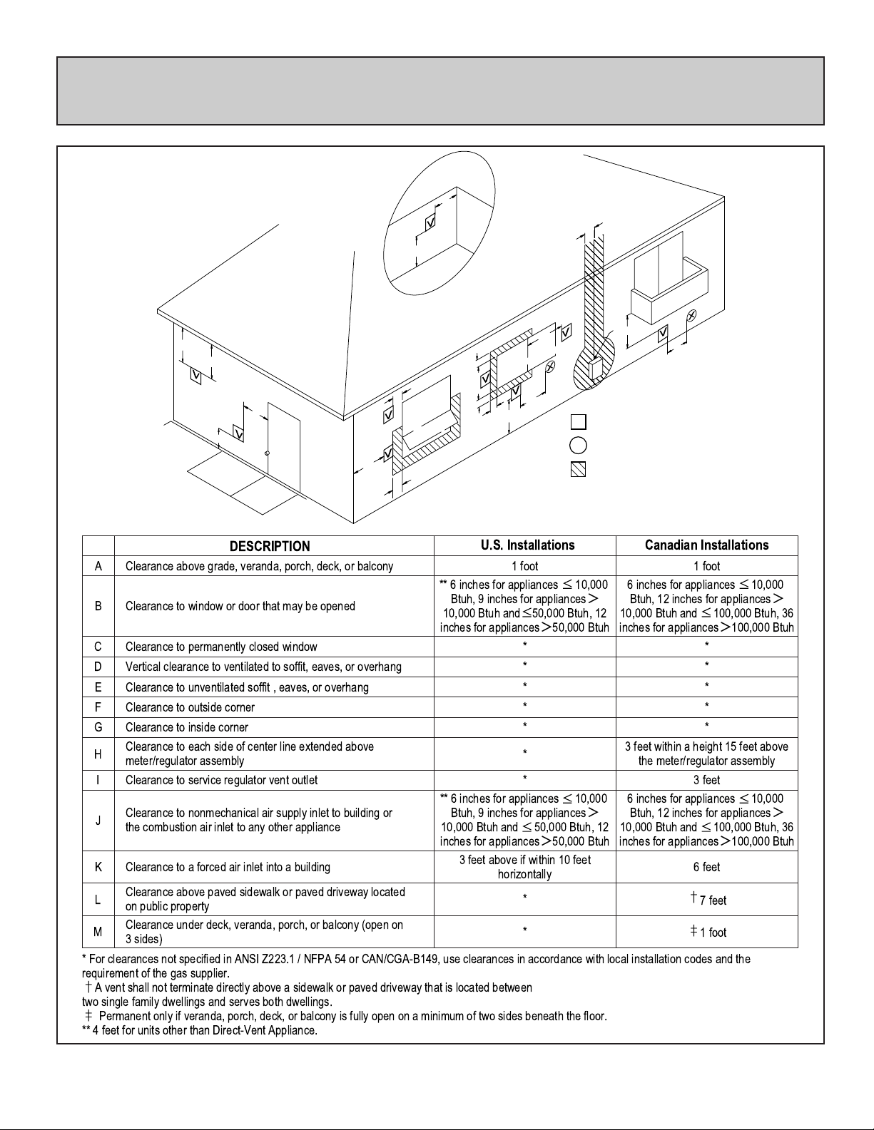
VENT TERMINATION CLEARANCES
INSIDE
CORNER DETAIL
G
H
A
I
B
OPERABLE
FIXED
CLOSED
D
E
B
M
K
B
J
B
A
VENT TERMINAL
V
AIR SUPPLY INLET
X
AREA WHERE
TERMINAL IS NOT
PERMITTED
1 foot
** 6 inches for appliances
Btuh, 9 inches for appliances
10,000
>
10,000 Btuh and 50,000 Btuh, 12
inches for appliances>50,000 Btuh
*
*
*
*
*
*
*
** 6 inches for appliances
Btuh, 9 inches for appliances
10,000 Btuh and
50,000 Btuh, 12
10,000
>
inches for appliances>50,000 Btuh
3 feet above if within 10 feet
horizontally
*
*
Canadian InstallationsU.S. Installations
1 foot
6 inches for appliances
Btuh, 12 inches for appliances
10,000 Btuh and
inches for appliances>100,000 Btuh
3 feet within a height 15 feet above
the meter/regulator assembly
3 feet
6 inches for appliances
Btuh, 12 inches for appliances
10,000 Btuh and
inches for appliances>100,000 Btuh
6 feet
†
‡
100,000 Btuh, 36
*
*
*
*
*
100,000 Btuh, 36
7 feet
1 foot
B
L
REF
A
Clearance above grade, veranda, porch, deck, or balcony
B
Clearance to window or door that may be opened
C
Clearance to permanently closed window
D
Vertical clearance to ventilated to soffit, eaves, or overhang
E
Clearance to unventilated soffit , eaves, or overhang
F
Clearance to outside corner
G
Clearance to inside corner
Clearance to each side of center line extended above
H
meter/regulator assembly
I
Clearance to service regulator vent outlet
Clearance to nonmechanical air supply inlet to building or
J
the combustion air inlet to any other appliance
K
Clearance to a forced air inlet into a building
Clearance above paved sidewalk or paved driveway located
L
on public property
Clearance under deck, veranda, porch, or balcony (open on
M
3 sides)
DESCRIPTION
C
FIXED
CLOSED
OPERABLE
F
B
* For clearances not specified in ANSI Z223.1 / NFPA 54 or CAN/CGA-B149, use clearances in accordance with local installation codes and the
requirement of the gas supplier.
†
A vent shall not terminate directly above a sidewalk or paved driveway that is located between
two single family dwellings and serves both dwellings.
‡
Permanent only if veranda, porch, deck, or balcony is fully open on a minimum of two sides beneath the floor.
** 4 feet for units other than Direct-Vent Appliance.
10,000
>
10,000
>
– 17 –
LOCATION / CLEARANCES
When positioning the heater the main points
governing the location are:
1. Flueing
2. Warm air distribution
This heater is not designed to be built in.
The flue terminal should be positioned away from
flammable materials.
Do not flue into natural draught flues or fireplaces,
this unit can only be used with one of the five types
of Rinnai flue kits. Do not flue unit into other rooms.
Flue terminal must be outside.
Flue may be positioned directly under opening
windows, with a minimum clearance of 9
" (230mm).
FLUE SIZES:
5 Flue lengths are available.
S flue walls 3
"〜4 1/2" (75〜115mm)
A flue walls 4 1/2"〜9 1/2" (115〜240mm)
B flue walls 9 1/2"〜15 3/4" (240〜400mm)
C flue walls 15 3/4"〜23 5/8" (400〜600mm)
D flue walls 23 5/8"〜31 1/2" (600〜800mm)
The flue is not designed to be positioned under
floors, or below the level of the heater.
Flue Terminal
LP GAS
Flue
Terminal
Flue
Terminal
 Loading...