


ENGLISH
Control-R™ Wi-Fi Module
Installation Manual
FOR YOUR RECORDS
If you have support questions, please call Customer Care and have your Control-R™ Wi-Fi module’s AYLA ID and Water Heater Serial Number available.
AYLA ID: ________________________________________________
(Located on back of Control-R™ Wi-Fi Module)
Water Heater Serial Number: _______________________________
(Located on side of water heater)
Rinnai Customer Care 1-800-621-9419 |
rinnai.us |
|
|
Rinnai Control-R™ Wi-Fi Module Installation Manual |
Page 1 of 30 |

TABLE OF CONTENTS
Thank You for Your Purchase |
3 |
About the Control-R™ Wi-Fi Module |
4 |
Specifications |
5 |
Unpack System Contents |
6 |
Select Module Location |
7 |
Install Module |
7 |
Mount the Module to a Wall |
8 |
Connect Module to Water Heater |
9 |
Connect to a Wi-Fi Network |
10 |
Connect to Wi-Fi on Apple® Devices |
11 |
Connect to Wi-Fi on Android® Devices |
19 |
LED Color Codes |
26 |
Troubleshooting |
27 |
Pairing Instructions |
28 |
Notes |
29 |
Rinnai Control-R™ Wi-Fi Module Installation Manual |
Page 2 of 30 |

Thank You for Your Purchase
Thank you for purchasing the Rinnai® Control-R™ Wi-Fi Module (referred to as module throughout this manual). Before installing and operating the module, be sure to read these instructions to familiarize yourself with the module’s features and functionality.
If You Need Service
Please call Rinnai Customer Care at 1-800-621-9419 Monday to Friday between 8 AM to 8 PM EST. Please have the following information available:
AYLA ID (Located on back of Control-R™ Wi-Fi Module)
Water Heater Serial Number (Located on side of water heater)
FCC Part 15
This device complies with Part 15 of the FCC rules. Operation is subject to the following two conditions:
This device may not cause harmful interference
This device must accept any interference received, including interference that may cause undesired operation
Please Read and Save This Manual for Future Reference
Rinnai Control-R™ Wi-Fi Module Installation Manual |
Page 3 of 30 |

About the Control-R™ Wi-Fi Module
With Rinnai’s Control-R™ Wi-Fi Module, new and existing Rinnai Residential and Commercial Tankless Water Heaters (2006 and newer) can be remotely monitored and controlled via smart devices. Rinnai now has the capability to provide a new option for management, control and maintenance of Rinnai Tankless Water Heaters.
Control and Monitoring
Control the Rinnai Tankless Water Heater from a smart phone or tablet to turn the system on/off, change the water temperature and monitor status.
Remote Diagnostics and Maintenance
Gives technicians detailed system information via automatic alerts and remote diagnostic tools before ever leaving their place of business, leading to shorter maintenance and repair times.
Accessibility and Convenience
Get instant access to technical bulletins, product warranty, product registration, manuals, step-by-step repair guides and more!
The Control-R™ Wi-Fi Module attaches easily to the Rinnai Tankless Water Heater by a two wire interface quickly connecting through the local Wi-Fi network. Once connected and the free Rinnai App is downloaded, the Rinnai Tankless Water Heater can be associated to the Rinnai independent dealer.
Rinnai Control-R™ Wi-Fi Module Installation Manual |
Page 4 of 30 |
Specifications
Part Number: RWM101
Works with all Rinnai Tankless Water Heater models manufactured 2006 and later (except the RH180 Hybrid Tank-Tankless Water Heater).
Note: The Lime Condition (LC) notification will not appear in the Rinnai App when the module is paired with the following series of Rinnai tankless water heaters manufactured prior to 2009: VA, VB, KA and V53e.
Attaches to the side of the water heater via the magnetic enclosure (indoor models only) or mounts to an indoor wall with supplied mounting hardware.
The module must be mounted indoors.
Pairs to only one Rinnai Tankless Water Heater.
Compatible with the following Wireless Demand Recirculation Accessories: Push Button, Motion Sensor and Temperature Sensor.
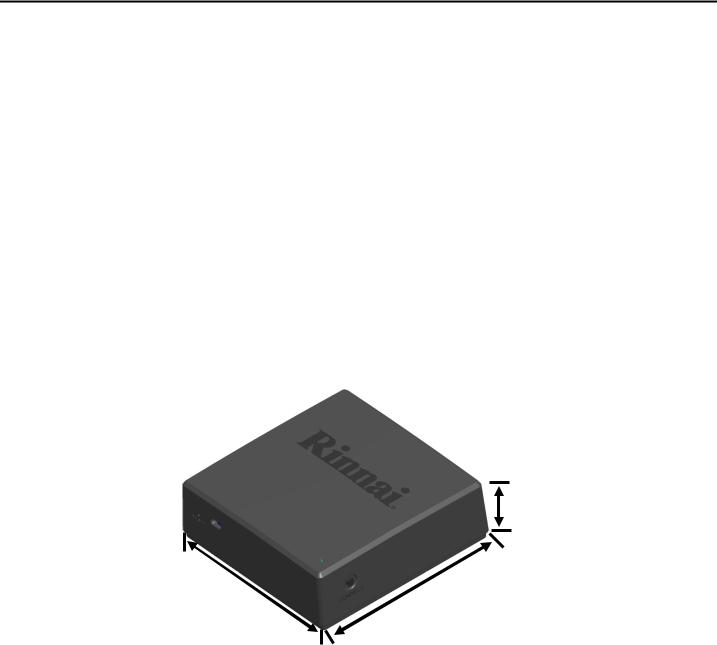
Dimensions(w,h,d):
|
Module: |
3.69”x3.69”x1.18” (94mmx94mmx29.97mm) |
|
ShippingCarton: |
6.125”x2.88”x6” (155.6mmx73mmx152.4mm) |
Depth
1.18”/29.97mm
Width |
Height |
3.69”/94mm |
3.69”/94mm |
Weight:
Module: 4.8oz (0.14kg) Shipping Carton: 6oz (0.17kg)
SupportedDevices:
Apple®devices(iPhone,iPad,etc.)runningoperating system8.0orhigher
Android®devices(phones,tablets,etc.)runningoperatingsystem4.4orhigher
BlackBerry®devicesare NOTsupported
Compatibility:
802.11NWi-FiNetworkupto2.4GHz
NOTCOMPATIBLEwiththeMC-195T-US orMC-100Vcontrollers
Rinnai Control-R™ Wi-Fi Module Installation Manual |
Page 5 of 30 |
Unpack System Contents
Carefully unpack your system contents. If any part of the system appears damaged, do not attempt to use it. Contact Rinnai Customer Care (1-800-621-9419) or your authorized Rinnai Service Provider.
WARNING: To avoid danger of suffocation, keep plastic bags out of the reach of children.
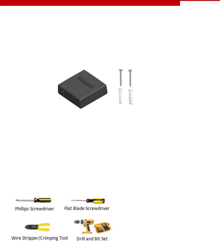
Check to be sure your system includes the following parts:
Rinnai Control-R™ Module (including 5 feet/1.5 meters of wire for water heater connection)
Wall mounting hardware (2 anchors/2 screws)
Rinnai Control-R™ Wi-FiModuleInstallationManual (thisdocument)
Required Devices, Tools and Information (Customer-Supplied)*
Mobile device connected to home/business network
Router with Wi-Fi
Wireless network name and Wi-Fi password
2.4GHZ Wi-Fi network with WPA 2 security protocols
Water Heater Serial Number or QR Code (located on water heater left side panel on cardboard packaging)
Tools (Below are example images of required tools and are used for illustrative purposes only. Your tools may differ from the images shown below.)
* Note: The above items, with the exception of the tools, are not required if operating only the WirelessDemand Recirculationaccessories(PushButton,Motion SensorandTemperatureSensor).
Note: Wire Stripper/Crimping Tool required only if
extending the length of the wires that connect the
module to the water heater.
Rinnai Control-R™ Wi-Fi Module Installation Manual |
Page 6 of 30 |

Select Module Location
Use the following guidelines to select a location for the module.
Choose a central location inside the home or business where the Wi-Fi signal is strong.
Note: If the water heater is located where the Wi-Fi signal is weak (such as basements or a mechanical room), the module is designed so that wiring can run up to 300 feet (91 meters) away from the tankless water heater to ensure a strong Wi-Fi signal (18-22 gauge wire is required).
Ensure that adequate space surrounds the module for service and support needs.
For outdoor water heaters, the module must be installed indoors.
The module is magnetic and can be placed on the side of the Rinnai tankless water heater (indoor models only) or mounted to a wall. See the next section for installation instructions.
Install Module
Two options are available for installing the module:
Option 1: Magnetic Mount
The module contains a strong magnetic backing and can easily be placed on the side of the water heater (indoor models only).
Option 2: Wall Mount
The module can be mounted to a wall with the supplied mounting hardware. Refer to the next section for steps on mounting the module to a wall.
Rinnai Control-R™ Wi-Fi Module Installation Manual |
Page 7 of 30 |
Mount the Module to a Wall
You Will Need:
Two (2) anchors and two (2) screws (supplied with system)
Tools shown in the Unpack System Contents section
Instructions:
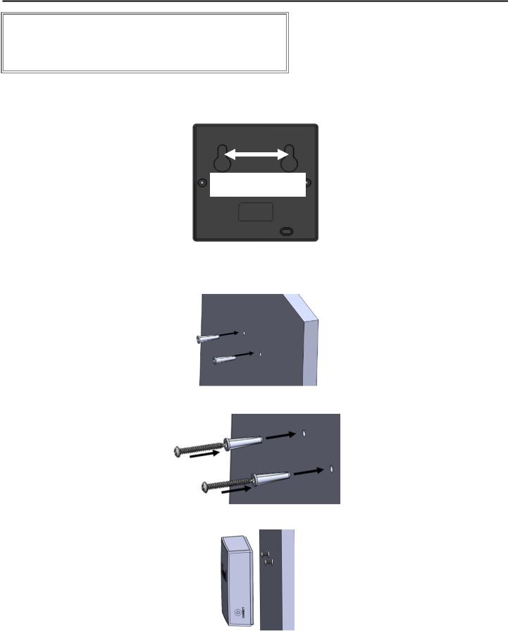
1.The module’s back panel contains two keyhole slots that support the module. Mark the location of each slot on the wall with a pencil. The distance between the two slots is 1.9” (48 mm).
1.9” (48 mm)
2.Use a level to ensure the slots are even. Use a power drill to drill pilot holes for the module screws and anchors.
3.Insert the supplied two wall anchors into each hole until they sit flush against the wall.
4. Insert the supplied screws into the anchors and fasten to the wall leaving 1/4” exposed.
5. Mount the module by placing the keyhole slots (on back of module) onto the screws.
Rinnai Control-R™ Wi-Fi Module Installation Manual |
Page 8 of 30 |
Connect Module to Water Heater
To protect yourself from harm, follow the steps below before wiring the
WARNING module:
Turn off the electrical power supply by unplugging the power cord or by turning off the electricity at the circuit breaker. The temperature controller does not control the electrical power.
Turn off the gas at the manual gas valve, usually located immediately below the water heater.
Turn off the incoming water supply. This can be done at the isolation valve immediately below the water heater or by turning off the water supply to the building.
1.Unplug the water heater.
Note: Pressing the ON/OFF button on the controller does not completely power off the water heater.
2.Remove the four (4) screws located on the water heater cover.
3.Two (2) wires are attached to the bottom of the module. Place these wires through the bottom opening of the water heater.
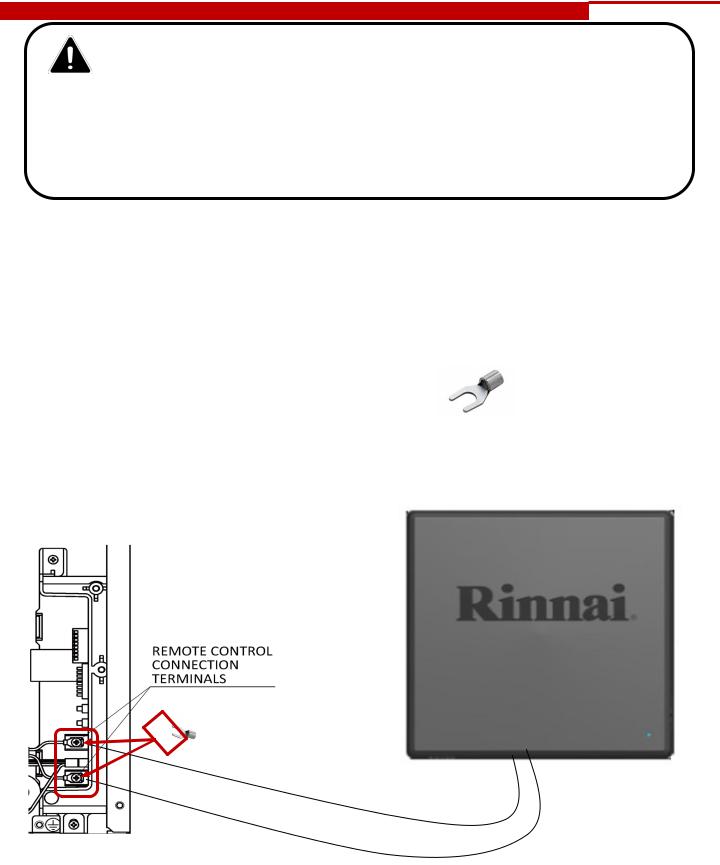
4.Attach each module wire to the remote control connection terminals by following the steps below.
a.Partially unscrew each of the two screws.
b.Insert the spade terminal (connected to the end of each wire) between the screw and the contact.
c. Tighten the screws. |
spade terminal |
|
|
5. Replace and tighten the four (4) screws on the water heater cover. |
|
Insert the spade terminal (located at end of wire) between the screw and contact.
Module Wires
Rinnai Control-R™ Wi-Fi Module Installation Manual |
Page 9 of 30 |
 Loading...