


Owner’s Operation and Installation Manual for the
RHFE-263FA |
|
Energysaver |
|
Gas Direct Vent Wall Furnace |
|
Table of Contents ........... |
2 |
Safety Information........... |
3 |
Operating Instructions..... |
6 |
Care and Maintenance.... |
10 |
Fault Codes .................... |
13 |
Installation Instructions ... |
14 |
Consumer Support.......... |
40 |
This appliance may be installed as an OEM installation in a manufactured home (USA only) or mobile home and must be installed in accordance with the manufacturer’s instructions and the Manufactured Home construction and Safety Standard, Title 24 CFR, Part 3280, in the United States, or the Mobile Home Standard, CAN/CSA Z240 MH Series, in Canada. This appliance is only for use with types of gas indicated on the rating plate. A conversion kit is supplied with the appliance.
This appliance may be installed in an aftermarket, permanently located, manufactured home (USA only) or mobile home, where not prohibited by local codes.
This appliance is only for use with the type of gas indicated on the rating plate. This appliance is not convertible for use with other gases, unless a certified kit is used.
Table of Contents
Consumer Safety Information |
|
Safety Definitions ........................................ |
3 |
Safety Behaviors and Practices.................. |
3 |
Safety Features........................................... |
4 |
Specifications |
|
Appliance Specifications ......................... |
4, 5 |
Features...................................................... |
5 |
Flue Manifolds............................................. |
5 |
Operating Instructions |
|
Getting to Know your RHFE-263FA ......... |
6 |
Control Panel .............................................. |
7 |
Operating Information |
|
Turning ON and OFF ............................. |
8 |
Adjusting the temperature ..................... |
8 |
Economy Mode...................................... |
8 |
Function Lock ........................................ |
9 |
Adding Water to the Humidifier.............. |
9 |
Adjusting Air Flow Direction................... |
9 |
Sensible Temperature Control............... |
9 |
Care and Maintenance |
|
Maintenance ........................................ |
10 |
Care of Exterior.................................... |
10 |
Snow Accumulation ............................. |
10 |
Filters ................................................... |
10 |
Visual Inspection of Flame .................. |
10 |
Before Making a Service Call |
....................11 |
Troubleshooting......................................... |
12 |
Fault Codes ............................................... |
13 |
Installation Instructions |
|
General Instructions .................................. |
14 |
Gas Connection......................................... |
15 |
Clearances to Combustibles ..................... |
15 |
Installation Parts ....................................... |
16 |
Drilling Flue Hole ....................................... |
17 |
Dimensions................................................ |
17 |
Flue Terminal Clearances ................... |
18, 19 |
Flue Manifold Installation..................... |
20, 21 |
Extension Kit Installation ......................... |
22 -24 |
Connecting the Appliance ......................... |
25 |
Operating Instructions ............................... |
26 |
Cut-Away Diagram .................................... |
27 |
Wiring Diagram.......................................... |
28 |
Ladder Diagram......................................... |
29 |
Flow Diagram ............................................ |
30 |
Parts List.............................................. |
31 -39 |
Consumer Support |
|
Warranty Information................................. |
40 |
Limited Warranty .................................. |
40,41 |
2 |
Rinnai Corporation RHFE-263FA |

Consumer Safety Information
Safety Definitions
This is the safety alert symbol. This symbol alerts you to potential hazards that can kill or hurt you and others.
 DANGER
 WARNING
 CAUTION
Indicates an imminently hazardous situation which, if not avoided, will result in death or serious injury.
Indicates a potentially hazardous situation which, if not avoided, could result in death or serious injury.
Indicates a potentially hazardous situation which, if not avoided, could result in minor or moderate injury. It may also be used to alert against unsafe practices.
Safety Behavior and Practices
 Do not insert items into the louvers.
 Do not spray aerosols near the appliance while it is operating. Most aerosols contain butane gas which is flammable.
 Do not unplug the appliance while it is operating or while the fans are on.
Rinnai Corporation RHFE-263FA |
3 |

Safety Features
 Overheat: The appliance will automatically shut down when the appliance exceeds a predetermined temperature.
 Flame Failure: The appliance will automatically shut down if the burner flame is extinguished.
 Power Failure: The appliance will cut off the gas if it loses electrical power.
 Power Surge Fuse: A glass fuse on the PC board protects against overcurrent. If the fuse blows then all indicator lamps will be off.
 Spark Detector: The appliance automatically shuts down if there is an abnormal spark at ignition.
 Fusible Link: In case the overheat feature prevents the temperature from rising then the fusible link will break shutting off the appliance.
|
|
Specifications |
|
||
|
Appliance Specifications |
|
|
|
|
|
|
|
|
|
|
Application |
For manufactured home (USA only) or mobile home or residential installation |
|
|||
|
|
convertible for use with natural gas and liquefied petroleum gases (propane / |
|
||
|
|
LPG) when provision is made for the simple conversionfrom one gas to the |
|
||
|
|
other. |
|
|
|
|
|
|
|
|
|
General Description |
Forced combustion, forced convection, flued gas furnace |
|
|||
|
|
|
|
|
|
Operation |
Push button electronic |
|
|
|
|
|
|
|
|
|
|
Gas Connection |
1/2 in female NPT |
|
|
|
|
|
|
|
|
|
|
Gas Control |
Electronic |
|
|
|
|
|
|
|
|
|
|
Burners |
Stainless steel Bunsen burner |
|
|||
|
|
|
|
|
|
Temperature Control |
Electronic thermostat |
|
|
|
|
|
|
|
|
|
|
Ignition System |
Electronic spark ignition |
|
|||
|
|
|
|
|
|
Flue System |
The flue must be terminated to atmosphere with only flue components listed |
|
|||
|
|
with the appliance’s certification. Warranty will be voided if non listed |
|
||
|
|
components are installed. |
|
||
|
|
|
|
|
|
Humidifier Tray |
Capacity - 1.5 pints (700 cc) |
|
|||
|
|||||
|
|
|
|
|
|
Electrical Connection |
AC 120V, 60 Hz, 47 watts |
|
|||
|
|
|
|
|
|
Weight |
37 lbs (17 kg) |
|
|
|
|
|
|
|
|
|
|
Noise Level |
31-38 dB |
|
|
|
|
|
|
|
|
|
|
Fan CFM output |
Low 96.4 - High 128.5 |
|
|
|
|
|
|
|
|
|
|
AFUE Rating |
Natural Gas: 80% |
Propane: 80% |
|
||
|
|
|
|
|
|
Rinnai is continually updating and improving products. Therefore, specifications are subject to change without prior notice.
The efficiency rating of this appliance is a product thermal efficiency rating determined under continuous operating conditions and was determined independently of any installed system.
4 |
Rinnai Corporation RHFE-263FA |
Appliance Specifications
|
Natural Gas |
Propane Gas |
|
|
|
Minimum supply gas pressure |
3.5 in (89 mm) W.C. |
8.0 in (203 mm) W.C. |
|
|
|
Maximum supply gas pressure |
10.5 in (267 mm) W.C. |
13.0 in (330 mm) W.C. |
|
|
|
Manifold test pressure-Low |
0.6 in (16 mm) W.C |
1.1 in (27 mm) W.C. |
|
|
|
Manifold test pressure-High |
2.3 in (58 mm) W.C. |
3.7 in (94 mm) W.C. |
|
|
|
BTU/hour input |
Low 5500 - High 11000 |
Low 5700 - High 11000 |
|
|
|
BTU/hour output |
Low 4450 - High 8800 |
Low 4600 - High 8800 |
|
|
|
Features
 Clean Heating Forced Flue Type
 Easy Operation One-Touch Ignition
 Sensible Temperature Control Feature
 Comfortable Room Temperature Control and
Display
 Warm Air Outlet at Floor Level (keeps your feet warm)
 Function Lock
 Room Temperature Setting Memory
 Clean the Air Filter - Indicator Lamp
 Energy Saving Economy Setting
 Humidifier Tray
 Air Flow Directional Louvers
 Direct Vent Easily Installed
 Proportional Heating Variable Capacity
 Hush! Quiet Operation
 Modern Design Minimizes Floor Space
Requirements
 Failure Message Display
Flue Manifolds
See the installation instructions for the parts list of the vent kit.
The A Vent Kit is included with the appliance.
The following flue manifold sizes are available:
Name |
Kit No. |
|
fits walls |
|
|
|
|
|
|
S Vent Kit |
FOT-150 |
|
3 - 4 1/2 in (75 - 115 mm) |
|
|
|
|
|
|
A Vent Kit |
FOT-151 |
4 |
1/2 - 9 1/2 in (115 - 240 mm) |
|
|
|
|
|
|
B Vent Kit |
FOT-152 |
9 1/2 - 15 3/4 in (240 - 400mm) |
|
|
|
|
|
|
|
C Vent Kit |
FOT-153 |
15 |
3/4 - 23 5/8 in (400 - 600 mm) |
|
|
|
|
|
|
D Vent Kit |
FOT-154 |
23 |
5/8 - 31 1/2 in (600 - 800 mm) |
|
|
|
|
|
|
|
Rinnai Corporation RHFE-263FA |
5 |
||

Operating Instructions
Getting to know your new RHFE-263FA
6
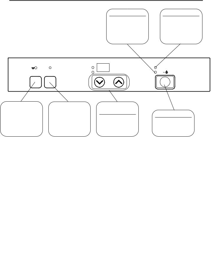
Control Panel
OPERATION LAMP
This lamp turns when "green" when power
is on. Lamp will change to "red" when burner is on.
Function |
|
Set Temp |
Economy |
RoomTemp |
|
Lock |
|
|
FUNCTION |
|
ENERGY SAVING |
LOCK |
|
BUTTON |
Lamp is "green" |
|
Lamp is "green" |
when this feature |
|
when this feature is |
is on. |
|
activated. |
>
>
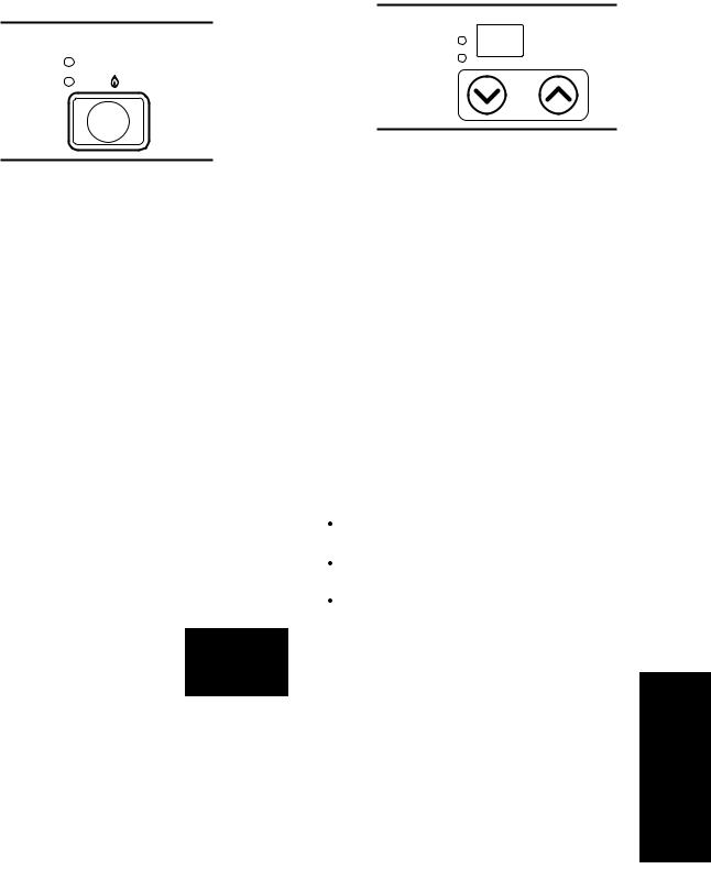
ON/OFF BUTTON
Easy operation One touch ignition
operated.
Rinnai Corporation RHFE-263FA |
7 |
Operating Information
Turning the heater ON |
Adjusting the Temperature |
|
Set Temp |
Filter |
RoomTemp |
|
|
ON |
Temp |
|
|
|
Control |
ON/OFF |
|
When you press the ON/OFF button, the LED display will illuminate, the combustion fan will begin to run, and the spark will ignite the main burner.
This heater has an automatic ignition system. When the main burner has lit, the combustion lamp will glow red, and the spark will stop.
If ignition does not occur after 15 seconds, the appliance will automatically turn off and a fault code will be displayed on the control panel. This may occur when using the appliance for the first time or if it has not been used for a while. Try operating the appliance again.
There may be a smell of burning dust or oil the first time the heater is lit or when the heater has been out of operation for a long time.
The appliance may make noises after ignition or when it is turned off. This is normal and is due to the thermal expansion or contraction of its components.
Turning the heater OFF
Press the ON/OFF button. Do not |
ON/OFF |
turn off by unplugging at the power |
|
outlet. |
|
The fan will continue to run for a short time to prevent the internal components from overheating.
The temperature setting and the room temperature are indicated by the L.E.D. display on the control panel. When the appliance is turned on the temperature setting will be displayed for 10 seconds. The display will then show the room temperature. The default temperature setting is 72°F.
To change the temperature setting press one of the temperature control buttons once. The “Set Temp” should light up and the display will show the current temperature setting. Continue to press the control buttons until the desired temperature setting is reached. After 10 seconds the display will return to showing the room temperature.
The thermostat automatically modulates the burner and the fan to maintain the temperature setting.
The temperature settings available are:
LO - burner is on minimum combustion
60°F - 80°F in two degree increments
HI - burner is on maximum combustion
Economy Mode
Pressing the Economy button will cause the appliance to go into Economy Mode and the green lamp will glow. This results in the temperature setting being reduced by 2°F, 30 minutes after the room temperature has reached the temperature setting. After another 30 minutes the temperature setting is reduced another 2°F. This could result in the temperature setting being reduced by a
maximum of 4°F. The intent of this mode is to save energy.
8 |
Rinnai Corporation RHFE-263FA |

Operating Information
Function Lock |
|
|
|
This feature locks the buttons to prevent |
|
|
|
unintended operation. |
|
|
|
|
|
|
|
Press the Function Lock button to activate |
Function |
||
and the lamp will glow. Pressing and |
|
Lock |
|
holding the Function Lock button for two |
|
|
|
seconds will disengage the function lock. |
|
|
|
If the Function Lock is engaged while the |
|
|
|
unit is operating, all buttons will be |
|
|
|
disabled except for the ON/OFF button. |
|
|
|
If the Function Lock is engaged while the unit is off, then all buttons will be disabled.
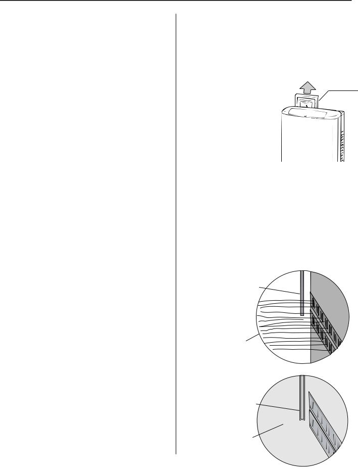
Adding Water to the Humidifier
Do not remove the bottom trim panel or the humidifier tray while warm air is flowing.
Warm air is humidified when it passes over the water in the tray.
To fill the tray, remove the bottom trim panel below the louvers by pulling on both sides. Pull the tray out and fill with water. Push the tray back in and attach the bottom trim panel. Do not operate the appliance unless the humidifier tray is installed.
During operation a small amount of condensation is produced in the flue system and drains into the humidifier tray.
Adjusting Air Flow Direction
Do not adjust the air flow louvers while warm air is flowing.
The vertical louvers may be adjusted to move the air flow more to the right or to the left.
Use a screw driver or similar object to bend each louver to the desired position.
Do not bend repeatedly (no more than 5 times) or else the louver will break.
The horizontal louver (which determines the vertical air flow direction) is fixed and cannot be adjusted.
Sensible Temperature Control
The sensible temperature control feature allows comfortable heating which matches the conditions in the room.
Based on the information collected by the room temperature thermistor when the heating starts, the heating capacity is automatically adjusted to achieve a comfortable heating effect and to reach the temperature setting quickly.
Rinnai Corporation RHFE-263FA |
9 |
Care and Maintenance
Maintenance
Repairs should be performed by a qualified service technician. The appliance should be inspected annually by a qualified service technician. More frequent cleaning may be required due to excessive lint from carpeting, bedding material, etc. It is imperative that control compartments, burners, and circulating air passage ways of the appliance be kept clean.
Any screen or guard removed for servicing the appliance must be replaced prior to operating the appliance. Clean as follows:
1.Turn heat off. Allow to cool for one hour.
2.Remove the front panel by removing six screws.
3.Use pressurized air to remove dust from the main burner, heat exchanger, and fan blades.
4.Use soft dry cloth to wipe cabinet.
Do not use wet cloth or spray cleaners on the burner.
The flue should be inspected annually for blockages or damage.
Motors are permanently lubricated and do not need periodic lubrication. Keep fan and motor free of dust and dirt by cleaning annually.
Verify proper operation after servicing.
Care of Exterior
Dampen soft cloth with warm water. Wring water out well and wipe the unit.
Do not use volatile substances such as benzene or thinners. They cause fading of the paint and deformation of the resin.
Snow Accumulation
Keep the area around flue terminal free of snow and ice. The appliance will not function properly if the intake air or exhaust is impeded by obstructions.
Filters
Dirty filters reduce the air flow and the appliance’s ability to produce heat. The filters should be cleaned frequently during the heating season. If the filters become blocked the filter indicator lamp will flash red. Eventually the appliance will turn off and display fault code 14 on the control panel display.
To clean the filters, the |
AIR FILTER |
|
appliance should be OFF |
|
|
and cool. Remove the |
|
|
filter and clean it using a |
|
|
soft dry cloth or vacuum. |
|
|
If the filter is greasy wash |
|
|
with warm soapy water, |
|
|
rinse, and dry |
|
|
completely. |
|
|
|
|
|
Visual Inspection
of Flame
Check that the burner The flame can be seen through the louvers.
When operating normally the burner flame should appear as long, clear, blue, stable, streaks. Yellow flames or an orange color is abnormal and maintenance is required.
NORMAL
Flame Rod
Long, clear, blue, stable flames
ABNORMAL
Flame Rod
Yellow flames or orange color
10 |
Rinnai Corporation RHFE-263FA |

Before Making a Service Call
Before making a service call please check the following:
■ At Ignition:
Heater does not operate.
Is the heater plugged in?
Have the fuses or breaker blown at the fuse box / breaker panel? Is there a power failure?
Is the air filter blocked?
Is anything blocking the outlet for the hot air? Is the flue blocked?
Warm air does not flow when the burner lights.
Smoke or strange smells are produced on the first trial light up after installation.
Sharp clicking noises at ignition, or when unit cuts down on the thermostat, or goes out.
The fan is started automatically after a short delay.
This is to allow the heat exchanger to warm up, helping to avoid cold draughts.
This is caused by grease or oil and dust on the heat exchanger and will stop after a short time.
This is simply expansion noise from the heat exchanger.
■ During Combustion:
Clunking noise when the thermostat operates.
Unit is not heating room.
Air filter is blocked or the louvers are blocked or obstructed.
Heater will not re-ignite after overheating.
■ When the unit is turned off.
Convection fan continues to run after turning OFF.
■ Other Points:
Steam is discharged from the flue terminal.
This is the sound of the solenoid gas valves opening and closing.
Is the air filter blocked?
Is the set temperature high enough?
Is the warm air outlet blocked by anything?
Are the doors and windows of the room closed?
Was the appliance correctly sized for the space?
Allow heater to cool, clean air filter, operate again.
Even after unit has cooled down, the heater does not ignite again. Repair is necessary.
Contact a qualified / authorized service provider.
This is to remove the residual heat from the heat exchanger. The fan will stop when the heater cools down.
High efficiency appliances tend to discharge water vapor on cold days. This is normal.
Unit cuts off without apparent reason.
Check whether filters are blocked. Dirty filters will cause the heater to overheat.
Power Failure. |
|
Switch OFF, then ON again when power is restored to re-set controls. |
|
|
|
Rinnai Corporation RHFE-263FA |
11 |
Troubleshooting
Problem
Cause
Not Plugged In
Power Failure
(Initial Installation)
Air In Gas Pipe
Gas Filter Blocked
Miss Ignition
Flue terminal obstructed
Flue manifold not connected
Louver obstructed
Air filter blocked
Gas Escape
Function Lock Set
Gas turned off at meter, tank, or valve.
Burner doesn’t ignite |
Unusual combustion |
Combustion stops during operation |
Smell of gas |
Noisy ignition |
Takes too long to warm the room |
|
|
|
|
|
|
Remedy
Push On/Off button to attempt restart after power is restored.
Purge air (Installer)
Service Call
Service Call
Clear obstruction
Service Call
Clear obstruction
Clean filter
Service Call
Cancel Function Lock
Turn gas on
12 |
Rinnai Corporation RHFE-263FA |

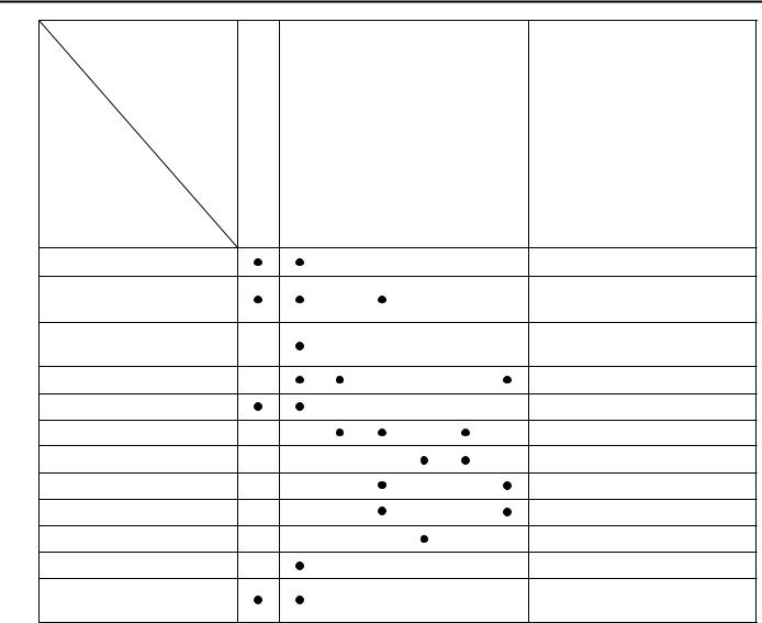
Fault Codes
If there is a malfunction the appliance may shut down as a safety precaution and display a fault code to assist in diagnosing the problem. The fault code will flash in the display on the control panel. When making a service call, this code will assist with diagnosing the fault.
You may be able to clear the fault code by turning the heater off and then on again. If the fault code remains or returns on the next operation, contact Rinnai or your nearest service agent and arrange for a service call.
CODE DISPLAYED |
FAULT |
REMEDY |
||
|
|
|
|
|
11 |
|
Ignition failure |
Check gas is turned ON. |
|
|
Service call if repeated. |
|||
|
|
|
|
|
|
|
|
|
|
12 |
|
Flame failure |
Check gas is turned ON. |
|
|
Service call if repeated. |
|||
|
|
|
|
|
|
|
|
|
|
14 |
|
Overheat |
Clean filter |
|
|
Service call if repeated. [1] |
|||
|
|
|
|
|
|
|
|
|
|
16 |
|
Room overheat |
Lower room temperature |
|
|
to less than 104°F(40°C). |
|||
|
|
|
|
|
|
|
|
|
|
31 |
|
Room Temperature |
|
|
|
|
Service call. |
||
32 |
|
Sensor faulty |
||
|
|
|||
|
|
|
|
|
|
|
|
|
|
33 |
|
Overheat Temperature |
|
Service call. |
|
|
|||
|
|
|
||
34 |
|
Sensor faulty |
|
|
|
|
|
||
|
|
|
|
|
|
|
|
|
|
|
|
|
||
|
|
|
|
|
53 |
|
Sparker failure |
|
Service call. |
|
|
|
|
|
61 |
|
Combustion fan failure |
|
Service call. |
|
|
|
|
|
70 |
|
Faulty ON/OFF switch |
|
Service call. |
|
|
|
|
|
71 |
|
Faulty solenoids |
|
Service call. |
|
|
|
|
|
72 |
|
Faulty Flame Rod |
|
Service call. |
|
|
|
|
|
73 |
|
Communication Error |
|
Turn heater OFF, |
|
|
then ON again. |
||
|
|
|
|
|
|
|
|
|
|
49 |
|
Sensor breakdown |
|
Service Call. |
|
|
|
|
|
99 |
|
Flue block |
|
Check around flue terminal [2] |
|
|
|
|
|
[1]Remove any obstructions. The flue needs to be kept clear to expel exhaust gases. If the appliance fails to operate contact a qualified service agency.
[2]If the fusible link needs replacement, it must be done by a qualified service agency. In addition, the cause of the overheat needs to be determined. The fusible link is a one use safety device that breaks to shut off the appliance.
Rinnai Corporation RHFE-263FA |
13 |
Installation Instructions
General Instructions
Do not use substitute materials.
Use only parts certified with the appliance.
A qualified service technician should install the appliance and inspect it before use.
If you move, check the gas type in your new area. The local gas authority will be able to advise on local regulations.
The installation must conform with local codes or, in the absence of local codes, with the National Fuel Gas Code, ANSI Z223.1/NFPA 54, or the Natural Gas and Propane Installation Code, CSA B149.1.
A manufactured home (USA only) or mobile home OEM installation must conform with the
Manufactured Home Construction and Safety Standard, Title 24 CFR, Part 3280, or, when such a standard is not applicable, the standard for
Manufactured Home Installations, ANSI/NCSBCS A225.1, or the standard for Gas Equipped Recreational Vehicles and Mobile Housing, CSA Z240.4.
The appliance, when installed, must be electrically grounded in accordance with local codes or, in the absence of local codes, with the National Electrical Code, ANSI/NFPA 70, or the Canadian Electrical Code, CSA C22.1.
Appliance input ratings are based on sea level operation and need not be changed for operation up to 2000 ft (609.9 m) elevation. For operation at elevations above 2000 ft (609.9m), manufactured to specified deration conditions for Canada and the United States. Refer to the Conversion Manual for high altitude installations.
The appliance and its appliance main gas valve must be disconnected from the gas supply piping system during any pressure testing of that system at test pressures in excess of 1/2 psi (3.5 kPa).
The appliance must be isolated from the gas supply piping system by closing its equipment shutoff valve during any pressure testing of the gas supply piping system at test pressures equal to or less than 1/2 psi (3.5 kPa).
If the flooring is carpet, tile, or other combustible material other than wood, then the appliance must be installed on a metal or wood panel extending the full width and depth of the appliance.
This appliance discharges a large volume of warm air next to the floor. Any particles in the air such as cigarette smoke could cause discoloration in nylon carpets containing dyes or vinyl surfaces.
This appliance is not designed to built in.
This appliance is only for use with the type of gas indicated on the rating plate. This appliance is not convertible for use with other gases unless a certified kit is used. If a conversion of the unit is needed, conversions must be performed by a qualified service provider at the owner’s expense.
This appliance must not be connected to a chimney flue serving a separate solid-fuel burning appliance.
Rinnai suggests that a dedicated electrical circuit with a 120VAC, 60 hz, 10 amp power source be used.
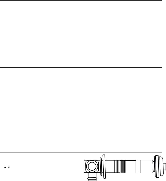
Two 1/8 in test plugs are provided for testing of manifold differential pressure. They are located on the modulating gas valve and on the burner manifold.
The appliance should be correctly sized for the space it required to heat.
Follow the installations instructions and those in Care and Maintenance for adequate combustion and ventilation air.
The flow of combustion and ventilation air shall not be obstructed.
Clearances to access the appliance during servicing are 2 inches (50 mm) from the sides, 40 inches (1 m) from the front, and 9 inches (225 mm) from the top.
14 |
Rinnai Corporation RHFE-263FA |
 Loading...