


Operation Installation Manual
Close Coupled
Solar Hot Water Systems -
Enduro SP200B and
Excelsior SP200BEX Collectors
This system shall be installed in accordance with:
•Manufacturer’s Installation Instructions
•Current AS/NZS 3500
•All applicable local rules and regulations including local OH&S requirements
This system must be installed, commissioned and serviced by an Authorised Person.
|
The solar hot and solar cold pipes between the solar storage tank |
|
and the solar collector(s) must be copper tube. Fittings used to |
|
join these pipes must use metallic materials to acheive sealing. |
|
Plastic pipe and fittings must not be used as they are not suitable |
IMPORTANT |
for the high temperatures and pressures that may occur. |
|
Failure of plastic pipe and/or fittings can lead to the release of high |
|
temperature water and can cause sever flooding and water damage. |
Not suitable as a pool or spa heater.
All Rinnai gas products |
W169 |
are A.G.A. certified. |
SAI Global |
Issue
3
AS/NZS 2712


 Lic No.1849
SAI Global

TABLE OF CONTENTS
Warnings and Important Information |
4 |
Safety and Regulatory Information 4 Scald Hazards 5 Operation Principle 6 Safety Devices 7 Excessive Discharge from Safety Devices 7 Gas Boosters 8 Hydrogen Gas 8 Water Temperature 8 Turning Off the Water Heating System 8 Turning On the Water Heating System 8 Water Quality 9 Draining and Filling the Water Heating System 9 Maintenance and Regular Care 9 Servicing and Repair 9
Save a Service Call |
10 |
Specifications |
12 |
General 12
Cylinder Weights 12
System Dimensions - Stainless Steel Cylinders 13
System Dimensions - Glass Lined Cylinders 14
Solar Collectors 15
Gas Boosters 16
Installation - All Systems |
17 |
Regulations and Occupation Health and Safety (OH&S) 17 Location 17 Water Pipes, Fittings and Insulation 18 Water Supply 18 Hot Water Delivery Temperature 19 Valves and Fittings 19 System Orientation and Inclination 20 Roof Mounting Options 21 Standard Installation 24 Roof pitch greater than 30° 28 Framed Installations - Cyclone Frame 29 Framed Installations - Flat, Reverse and Side Pitch 29 Connecting Fittings to Collector 31
Rinnai |
2 |
CC B OIM |

TABLE OF CONTENTS
180 Litre SS Cylinder with 1 SP200B or SP200BEX Collector - BIKS180CCT01C 32 180 Litre SS Cylinder with 2 SP200B or SP200BEX Collectors - BIKSUNICCT23C 34 330 Litre SS Cylinder with 2 SP200B or SP200BEX Collectors - BIKS330CCT02C 36 330 Litre SS Cylinder with 3 SP200B or SP200BEX Collectors - BIKSUNICCT23C 38 200 Litre Glass Lined Cylinder with 1 SP200B or SP200BEX Collector - BIKV200CCT01C 40 200 Litre Glass Lined Cylinder with 2 SP200B or SP200BEX Collectors - BIKV200CCT02C 42 330 Litre Glass Lined Cylinder with 2 SP200B or SP200BEX Collectors - BIKV330CCT02C 44 330 Litre Glass Lined Cylinder with 3 SP200B or SP200BEX Collectors - BIKV330CCT03C 46
Installation - Gas Boosted Systems |
48 |
Gas Booster Location 48
Gas Supply 48
Hot Water Delivery Temperature 48
SMARTSTART® 48
System Using Rinnai SmartStart 49
Gas Booster Clearances 50
Installation Procedure 51
Filling the System 52
Pre Solar Heating Checks 52
Solar Heating 53
Finishing the Installation 53
Draining Instructions 53
Installation - Electric Boosted Systems |
54 |
Installation Procedure 54
Filling the System 55
Pre Solar Heating Checks 56
Solar Heating 56
Finishing the Installation 56
Draining Instructions 56
Installation Record |
57 |
Notes |
58 |
Rinnai |
3 |
CC B OIM |

WARNINGSARNINGS A D IMPORTANTAND IMPORTANTNFORMATION INFORMATION
SAFETY AND REGULATORY INFORMATION
|
DO NOT operate this system before reading the manufacturers instructions. |
WARNING |
This appliance must be installed, commissioned and serviced by an authorised person in accordance |
|
with all applicable local rules and regulations. |
|
Access covers of water heating system components will expose 240V wiring and MUST only be removed |
|
by an authorised person. |
|
This appliance is not intended for use by persons (including children) with reduced physical, sensory or |
|
mental capabilities, or lack of experience and knowledge, unless they have been given supervision or |
|
instruction concerning use of the appliance by a person responsible for their safety. |
|
For continued safety of this appliance it must be installed, operated and maintained in accordance with |
|
the manufacturer’s instructions. |
|
Children should be supervised to ensure they DO NOT play with the appliance. |
|
Any power leads from the water heater system components MUST be plugged into an external |
|
weatherproof electrical outlet. If the power supply cord of any water heating components is damaged, it |
|
MUST BE replaced by an authorised person in order to avoid a hazard, using genuine replacement parts |
|
available from Rinnai. Take care not to touch the power plugs with wet hands. |
|
Care should be taken not to touch the pipe work as it may be HOT! |
|
The pipes between the solar collectors and storage cylinder MUST BE copper or an equivalent metallic |
|
material specified by Rinnai. Plastic pipe is NOT suited to the water temperatures and pressures that |
|
may occur in the system. |
|
DO NOT place articles on or against this appliance. |
|
DO NOT store chemicals or flammable materials near this appliance. |
|
DO NOT operate with collectors or covers removed from this appliance. |
|
NEVER use a flammable spray such as hair spray, lacquer, paint, etc near this unit as this may cause a |
|
fire. |
|
|
|
NOTICE TO VICTORIAN CONSUMERS |
|
This appliance must be installed by a person licensed with the Victorian Building Authority. |
|
Only a licensed person will have insurance protecting their workmanship. |
So make sure you use a licensed person to install this appliance and ask for your Compliance Certificate.
For Further information contact the Victorian Building Authority on 1300 815 127..
Rinnai |
4 |
CC B OIM |
WARNINGS AND IMPORTANT INFORMATION
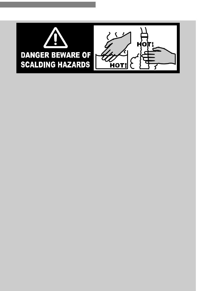
SCALD HAZARDS
HOT WATER CAN CAUSE SCALDS.
CHILDREN, DISABLED, ELDERLY AND THE INFIRM ARE AT THE HIGHEST RISK OF BEING SCALDED. FEEL WATER TEMPERATURE BEFORE BATHING OR SHOWERING.
SCALDS FROM HOT WATER TAPS CAN RESULT IN SEVERE INJURIES TO YOUNG CHILDREN.
SCALDS OCCUR WHEN CHILDREN ARE EXPOSED DIRECTLY TO HOT WATER WHEN THEY ARE PLACED INTO A BATH WHICH IS TOO HOT.
ALWAYS......
Test the temperature of the water with your elbow before placing your child in the bath, also carefully feel water before bathing or showering yourself.
Supervise children whenever they are in the bathroom. Make sure that the hot water tap is turned off tightly.
CONSIDER.....
Installing child proof tap covers or child resistant taps. Both approaches will prevent a small hand being able to turn on the tap.
Installing tempering valves or thermostatic mixing valves which reduce the hot water temperatures delivered to the taps. Your local plumbing authority may already require that these be fitted. Contact our installer or local plumbing authority if in doubt.
NEVER….
Leave a toddler in the care of another child. They may not understand the need to have the water temperature set at a safe level.
Rinnai |
5 |
CC B OIM |
WARNINGS AND IMPORTANT INFORMATION
OPERATION PRINCIPLE
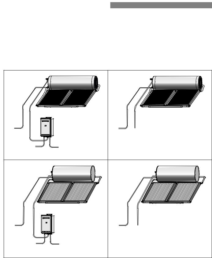
Close coupled systems are designed to have the solar collectors on the roof and the storage cylinder above the collectors, all mounted using available mounting brackets. Electric and gas boosted models are available. The system comprises of a hot water storage cylinder and solar collectors. Close coupled solar systems use the thermosyphon principle to circulate the water through the collectors and then to the storage cylinder without the need for a pump.
Supplementary heating is provided if insufficient heat is available from sun (such as during cloudy or rainy weather or during winter months) either via an electric heating element located inside the storage cylinder or via a gas booster located external to the storage cylinder. The following diagrams illustrates the systems set up for electric and gas boosting.
|
STORAGE CYLINDER |
|
STORAGE CYLINDER |
|
COLD WATER |
|
COLD WATER |
HOT WATER |
|
SUPPLY |
GAS BOOSTER |
SUPPLY |
||
DELIVERY |
||||
|
|
|
||
HOT WATER |
GAS SUPPLY |
|
|
|
DELIVERY |
|
|
|
|
Stainless Steel Gas Boosted Solar Hot Water System |
Stainless Steel Electric Solar Hot Water System |
|||
|
STORAGE CYLINDER |
|
STORAGE CYLINDER |
|
|
COLLECTORS |
|
COLLECTORS |
|
COLD WATER |
|
COLD WATER |
HOT WATER |
|
GAS BOOSTER |
SUPPLY |
DELIVERY |
||
SUPPLY |
||||
|
|
|||
HOT WATER |
GAS SUPPLY |
|
|
|
DELIVERY |
|
|
|
|
Glass Lined Gas Boosted Solar Hot Water System |
Glass Lined Electric Solar Hot Water System |
|||
Rinnai |
|
6 |
CC B OIM |
|
WARNINGS AND IMPORTANT INFORMATION
SAFETY DEVICES
The water heating system is supplied with various safety devices including temperature sensors, overheat sensors and switches and a Pressure & Temperature Relief (PTR) valve. These devices must not be tampered with or removed. The water heating system must not be operated unless each of these devices is fitted and is in working order.
DO NOT tamper with or remove safety devices.
WARNING DO NOT operate the water heater unless all safety devices are fitted and in working order.
DO NOT block or seal the PTR Valve and drain pipe.
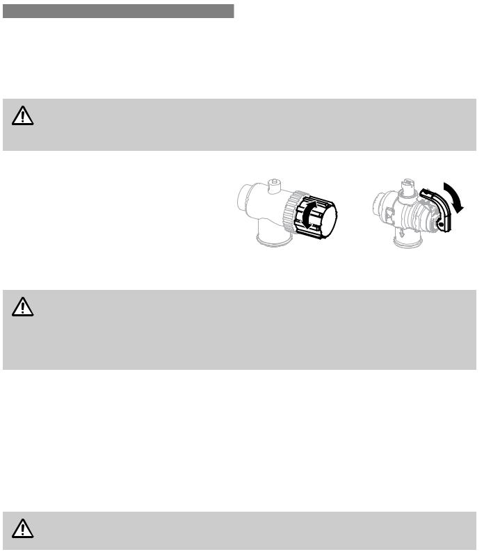
Pressure & Temperature Relief (PTR) Valve
This valve is located near the top of the water heater and is essential for safe operation. It is normal for the valve to release a small quantity of water through the drain line during heating.
However, continuous leakage of water from the valve and its drain line may indicate a problem with the water heater.
Tw ist cap until w ater flow s from drain line
Lift lever until w ater flow s from drain line (Low er lever gently!)
|
Never block the outlet of the PTR valve or it’s drain line for any reason. The easing gear must be |
|
operated at least every 6 months to remove lime deposits and verify that it is not blocked. Failure |
WARNING |
to do this may result in the water heater failing. |
|
If the valve does not discharge water when the easing gear lever is opened, or does not seal again when the easing gear is closed, attendance by an authorised person must be arranged without delay. The PTR valve is not serviceable.
EXCESSIVE DISCHARGE FROM SAFETY DEVICES Pressure & Temperature Relief (PTR) Valve
It is normal and desirable that this valve allows a small quantity of water to be discharged during the heating cycle. If it discharges more than a bucket of water during a 24 hour period or discharges continuously there may be another problem.
If the valve dribbles continuously, try easing the valve gear for a few seconds as described above. This may dislodge any foreign matter and alleviate the problem.
If the valve discharges at high flows, especially at night, it may be as a result of the water pressure exceeding the design pressure of the water heater. Ask your installer to fit a Pressure Limiting Valve (PLV).
NEVER replace the PTR valve with one which has a higher pressure rating than is specified for
WARNING your water heater.
Expansion Control Valve (ECV) - if fitted
It is normal and desirable that this valve allows a small quantity of water to be discharged during the heating cycle. If it discharges more than a bucket of water during a 24 hour period or discharges continuously there may be another problem.
If the valve leaks continuously, try easing the valve gear for a few seconds. This may dislodge any foreign matter and alleviate the problem. If this does not alleviate the problem contact Rinnai.
Operate the easing gear regularly to remove any lime deposits and to verify that it is not blocked.
Rinnai |
7 |
CC B OIM |

WARNINGS AND IMPORTANT INFORMATION
GAS BOOSTERS
•Do not touch the flue outlet or do not insert any objects into the flue outlet.
•Keep flammable materials, spray cans, fuel containers, trees, shrubs and pool chemicals etc, well clear of the flue outlet.
•Do not use the gas types other than those designated on the data plate. For example, do not use Propane/ Butane gas mixtures on appliances marked Propane Gas.
•Do not use Propane Gas on appliances marked as Natural Gas and vice versa.
HYDROGEN GAS
In the case of systems using a vitreous enamel lined cylinder, if the hot water unit is not used for two weeks or more, a quantity of hydrogen gas, which is highly flammable, may accumulate in the water heater. To dissipate this safely, it is recommended that a non electrically operated hot tap be turned on for two minutes at a sink, basin, or bath, but not a dishwasher or other appliance. During this procedure there must be no smoking, open flame or any electrical appliance operating nearby. If hydrogen is discharged through the tap, it will probably make a sound like air escaping.
WATER TEMPERATURE
The water gets heated by the solar energy contributed from the sun and heats the water until the water at the base of the storage cylinder reaches approximately 65°C. At this time water at the hot outlet can be up to 88°C. Continued heating is prevented by the ‘No Load’ protection, a Thermo-arrestor (TA) valve that prevents water passing from the cylinder to the collectors. During periods of low solar gain, supplementary heating occurs.
To meet Australian regulatory requirements, supplementary heating must be operational.
IMPORTANT
TURNING OFF THE WATER HEATING SYSTEM
If you plan to be away for only a few nights, we suggest you leave the water heating system switched on. If it is necessary to switch off the water heater, do so as outlined below:
Electric Boosted Systems
•Switch off the electrical supply to the supplementary heating element. The switch is usually marked and located in the electricity meter box of the dwelling.
Gas Boosted systems
•Switch off the electric supply to the gas booster.
TURNING ON THE WATER HEATING SYSTEM
Electric Boosted system
•Switch on the electric supply to the supplementary heating element(s). The switch is usually marked and located in the electricity meter box of the dwelling.
Gas Boosted systems
•Switch on the electrical supply to the gas booster.
Rinnai |
8 |
CC B OIM |

WARNINGS AND IMPORTANT INFORMATION
WATER QUALITY
The water quality of most public supplies is suitable for the water heating system. The water quality from bore wells is generally unsuitable for the water heating system. Refer to the separate warranty document for water quality parameters and how they affect the warranty conditions. If in doubt about the water quality, have it checked against the parameters listed in the warranty document. The system is not suitable as a pool or spa heater.
DRAINING AND FILLING THE WATER HEATING SYSTEM
Draining or filling normally occur only during installation or servicing and must be carried out by an authorised person.
MAINTENANCE AND REGULAR CARE
Operate the easing gear of the PTR as described in the section ‘Safety Devices’ on page 7.
SERVICING AND REPAIR
Our Servicing network personnel are fully trained and equipped to give the best service on your appliance. If your appliance needs service, ring one of the service contact numbers on the back of this booklet.
It is recommended that the system be serviced at least every 5 years.
The pressure and temperature relief valve and expansion control valve must be checked for performance or replaced by an authorised person at intervals not exceeding 5 years or more frequently in areas where the water is classified as scaling water (refer to the supplied warranty booklet).
It is recommended that the sacrificial anode fitted to Glass Lined cylinders be inspected every 5 years or more frequently in areas where there is a high incidence of water deposits. This does not apply to Stainless Steel cylinders. Anodes suited to hard and soft water, are available from Rinnai.
If the electric conduit, power supply cord or plug to the water heater is damaged, they must be replaced by an authorised person in order to avoid a hazard. The power supply cord and plug (if fitted) must be replaced by a genuine replacement part available from Rinnai.
Rinnai |
9 |
CC B OIM |

SAVE A SERVICE CALL
Before contacting Rinnai for service, please follow the fault finding guide. If the problem persists or this information doesn’t answer your questions, contact Rinnai on the phone number on the back of this manual
Service call outs attending to any condition or fault that is not related to Rinnai product or components may be chargeable.
INSUFFICIENT OR NO HOT WATER
Excessive hot water |
|
Electric Boosted Systems: |
consumption |
|
Often people are surprised at the amount of hot water used, especially when |
|
|
|
|
|
showering. If the amount of hot water used during the day exceeds the storage capacity |
|
|
of the cylinder, it is likely that there will be insufficient hot water. |
|
|
Gas Boosted Systems: |
|
|
Insufficient flow may occur if multiple outlets are in use at the same time and exceed |
|
|
the rated flow capacity of the gas booster. If so, reduce the number of outlets in use. |
|
|
Consider discussing with your installer, fitting water saving fixtures and/or flow control |
|
|
or pressure limiting valves to reduce consumption. |
Incorrect solar system size |
|
The system may not have been adequately sized to suit the household. |
Temperature and pressure |
|
PTR Valves & ECV Valves (if fitted) |
relief valve / expansion |
|
It is normal and desirable that these valves allows a small quantity of water to be |
control valve discharging |
|
|
|
discharged during the heating cycle. If they discharges more than a standard bucket |
|
water continuously |
|
|
|
of water during a 24 hour period or discharges continuously there may be another |
|
|
|
|
|
|
problem |
|
|
If water continuously dribbles from the valve, try easing the valve gear for a few |
|
|
seconds as described in the section ‘Maintenance and Regular Care’ on page 9. |
|
|
This may dislodge any foreign matter and alleviate the problem. |
|
|
If the valve discharges at high flows, contact your installer or Rinnai to discuss. |
Booster heating not |
|
Electric boosted Systems: |
operating for electric |
|
Check to ensure the electric isolating switch(es) at the switchboard (usually marked |
systems |
|
|
|
“Hot water” or “water heater”) is switched ‘ON’. |
|
|
|
|
|
|
Check to ensure that the electric fuses for hot water at the switchboard are intact |
|
|
If running on Off-Peak, discuss boosting times with electricity supplier. |
|
|
Booster heating not operating or insufficient gas supply for gas boosted heating system |
Gas booster not operating |
|
Gas Boosted Systems: |
or insufficient gas supply |
|
Check to ensure the power cord of the gas booster is plugged in and switched ‘on’. |
for gas boosted heating |
|
|
|
|
|
system |
|
Check gas is available and the isolation valve is opened |
|
|
Close the hot tap and wait for 10 seconds and open it again. The hot tap must be |
|
|
opened enough to ensure that the flow rate is sufficient for the gas booster to light. |
|
|
Check if there is gas supply to other appliances in the rest of the house |
Booster thermostat settings |
|
Electric Boosted Systems: |
|
|
Check the temperature of hot water delivered with a thermometer placed under the |
|
|
closest outlet (usually the kitchen sink) on a non-tempered hot water line |
|
|
This test should be done early in the morning after overnight electrical boosting before |
|
|
any hot water is used. The temperature of the water delivered should be at least 55°C |
|
|
(allowing for heat losses in pipe work) |
|
|
If this is not the case or the temperature may need to be increased. Contact your |
|
|
installer or Rinnai to discuss adjusting the thermostat. |
NO WATER FROM THE HOT TAP |
|
|
Restriction in the hot tap |
|
Check for water flow at the other hot taps and that the cold water isolation valve is fully |
or failure of the cold water |
|
open |
supply to the heater |
|
|
Rinnai |
10 |
CC B OIM |
SAVE A SERVICE CALL
HIGH ELECTRICITY OR GAS BILL
Hot water usage patterns |
Electric Boosted Systems: |
|
If using an off peak (overnight) boosted electrical system, the time of use of the water |
|
may affect whether heating is done by electric element or solar energy. This is because |
|
both solar heated water and electrically heated water are stored in the same cylinder. |
|
As the element is in the middle of the tank, half the tank can be heated each night by |
|
the booster element. |
|
If the bulk of hot water is used in the morning, there will be cold water in the cylinder for |
|
the sun to heat during the day leading to lower electricity usage. |
|
If the bulk of the hot water is used in the evening, the electric element will reheat the |
|
water overnight. In the morning there will only be half a cylinder of cold water for the |
|
sun to heat. |
|
Consider changing your usage pattern to optimise solar energy usage. |
High electricity cost |
Electric Boosted Systems: |
|
The electricity tariff will determine the running costs of the system. Contact the |
|
electricity supplier to confirm what these tariffs are. |
Temperature and pressure |
See entry under ‘Insufficient or No Hot Water’ |
relief valve / expansion |
|
control valve discharging |
|
water continuously |
|
Lack of solar gain |
Reduced sunlight due to overcast weather in summer or low solar contribution in winter |
|
will result in an increased dependence on electricity or gas boosting. Higher electricity |
|
or gas bills under these conditions, especially in winter, are normal. |
|
If the solar collectors are shaded by trees or other objects, or the glass is dirty, the |
|
effectiveness of the collectors is greatly reduced. Arrange for trimming of the trees or |
|
relocation of the solar collectors if the obstruction is permanent. Arrange for cleaning of |
|
the collector glass |
|
Solar collectors incorrectly positioned will also severely affect the solar gain. Check that |
|
positioning and alignment of solar collectors is in accordance with the section ‘System |
|
Orientation and Inclination’ on page 20. |
CONDENSATION IN COLLECTORS |
|
Condensation in solar |
There is a small amount of ventilation between atmosphere and the internals of the |
collectors |
solar collector to ensure efficient operation. Under certain weather conditions, water |
|
vapour naturally present in the air may condense on the inside surface of the collector |
|
glass. This does not affect the performance of the system. If you are concerned contact |
|
Rinnai to discuss. |
NOISY SOLAR COLLECTORS |
|
Noise from solar collectors |
Occasionally on days of high solar gain, the water temperature in the collector may |
|
become very high. The noise may be similar to a boiling kettle, or an expanding |
|
contracting metallic sound. The collector is designed to withstand these conditions, and |
|
no action is needed, unless it is extreme. Contact Rinnai to discuss if you have any |
|
concerns. |
WATER HAMMER |
|
Hot and cold water |
Contact your installer or a plumber to discuss checking the clipping of hot and cold |
plumbing in the premises |
water pipe work and install a pressure limiting valve or water hammer arrestor as |
|
required |
Rinnai |
11 |
CC B OIM |

SPECIFICATIONS
GENERAL
Close Coupled hot water systems are specified according to the cylinder capacity, number of solar collectors and boost type and capacity. Boost capacity for gas boosted system depends on the gas booster model selected. Boost capacity for electrically boosted systems depends on the power rating of the electric heating element.
Specifications for the various components are shown below.
Solar flow and return connection: |
Rp ¾ |
|
PTR valve connection: |
Rp ¾ |
|
Cold inlet connection: |
Rp ¾ |
|
Hot outlet connection: |
Rp ¾ |
|
PTR valve setting |
850 kPa |
|
Rating of PTR Valve supplied |
10 kW |
|
Expansion Control Valve (ECV) setting |
700 kPa |
|
(supplied by installer if required) |
||
|
||
Max supply pressure with ECV |
500 kPa |
|
Max supply pressure without ECV |
700 kPa |
|
Pressure limiting valve rating |
500 kPa |
|
(supplied by installer if required) |
||
|
||
|
2.4 or 3.6 kW standard |
|
Electric element power rating |
1.8 or 4.8 kW available for stainless steel cylinders |
|
|
4.8 kW available for glass lined cylinders |
CYLINDER WEIGHTS
|
Mass of Cylinder |
Mass of Cylinder |
|
(empty) |
(filled) |
Stainless steel 180 litre |
40 kg |
225 kg |
Stainless steel 330 litre |
80 kg |
412 kg |
Glass lined 200 litre |
77 kg |
277 kg |
Glass lined 330 litre |
104 kg |
434 kg |
Rinnai |
12 |
CC B OIM |
SPECIFICATIONS
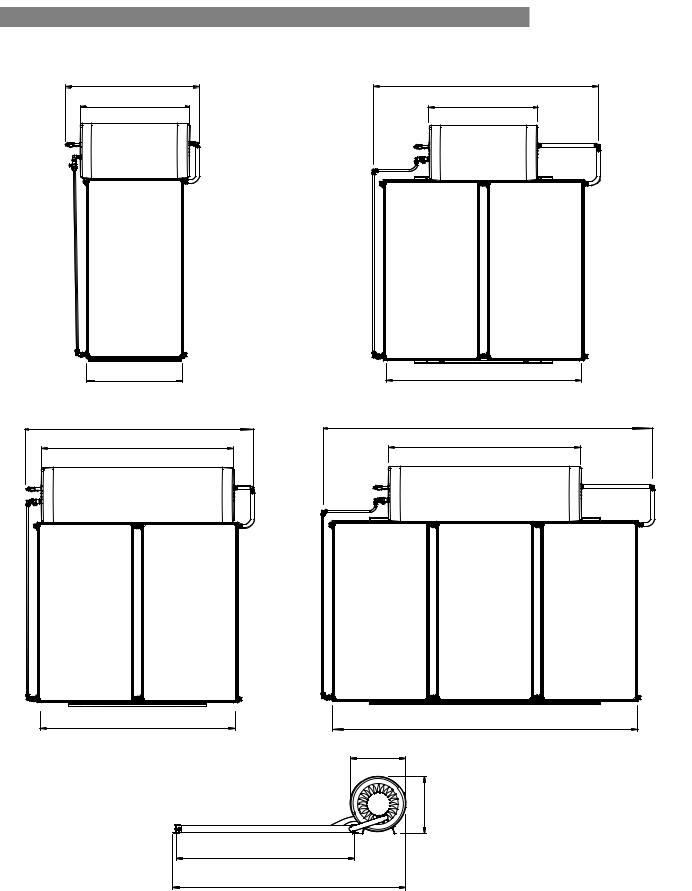
SYSTEM DIMENSIONS - STAINLESS STEEL CYLINDERS
1450 |
2470 |
|
1200 |
2470 |
2090 |
2175 |
3600 |
2090 |
2175 |
3310 |
|
600 |
610
1960
2580 *
*This dimension may vary slightly depending on the installed spacing between the cylinders and the collectors
Rinnai |
13 |
CC B OIM |
SPECIFICATIONS
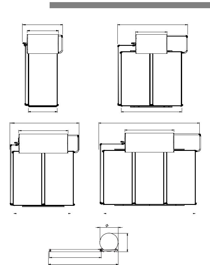
SYSTEM DIMENSIONS - GLASS LINED CYLINDERS |
|
1430 |
2470 |
|
|
1140 |
1140 |
|
1050 |
2175 |
2470 |
3610 |
1735 |
1735 |
2175 |
|
|
3310 |
685 |
695 |
1960 |
2610 * |
* This dimension may vary slightly depending on the installed spacing between the cylinders and the collectors
Rinnai |
14 |
CC B OIM |

|
|
|
SPECIFICATIONS |
|
SOLAR COLLECTORS |
|
|
|
|
|
|
|
|
|
|
ENDURO |
|
EXCELSIOR |
|
|
SP200B |
|
SP200BEX |
|
Type |
Flat plate |
|
Flat Plate |
|
|
|
|
|
|
Waterways |
Copper |
|
Copper |
|
|
|
|
|
|
Absorber |
Aluminium |
|
Copper |
|
|
|
|
|
|
Selective Surface |
High Performance |
|
Sputtered Titanium Oxide |
|
|
|
|
|
|
Maximum Operating Pressure |
1000 kPa |
|
1000 kPa |
|
|
|
|
|
|
Casing Material |
Aluminium |
|
Aluminium |
|
|
|
|
|
|
Overall Dimensions |
1960 x 1050 x 80 |
|
1960 x 1050 x 80 |
|
(L x W x H) (mm) |
|
|||
|
|
|
||
Weight empty (kg) |
40 |
|
40 |
|
|
|
|
|
|
Water volume (litres) |
1.95 |
|
2.0 |
|
|
|
|
|
|
Number risers |
9 |
|
10 |
|
|
|
|
|
|
Potential Solar Output at |
1.25 kW |
|
1.25 kW |
|
PTR relief conditions (kW) |
|
|||
|
|
|
||
|
The Rinnai solar hot water warranty booklet specifies the locations and |
|||
|
conditions that apply for flat plate collectors to be warranted against frost |
|||
|
|
damage. |
||
|
In locations where the warranty booklet specifies that frost valves must be |
|||
Frost Protection |
used, they must be fitted for warranty to apply. If frost valves are missing |
|||
you must obtain them and fit them. Failure to fit frost valves will void any |
||||
|
||||
|
warranty against frost damage. |
|||
|
For full warranty terms, conditions and exclusions refer to the Rinnai |
|||
|
warranty booklet for solar hot water. |
|||
|
This booklet is available at www.rinnai.com.au. |
|||
Rinnai |
15 |
CC B OIM |

SPECIFICATIONS
GAS BOOSTERS
Model Name |
S20 |
S26 |
|
S26i * |
S32 |
* |
|
|
|
|
|
|
|
Boost capacity at 20°C rise (l/min) |
20 |
26 |
|
32 |
37 |
|
|
|
|
|
|
|
|
Boost capacity at 25°C rise (l/min) |
16 |
26 |
|
26 |
32 |
|
|
|
|
|
|
|
|
Maximum rated flow (l/min) |
20 |
26 |
|
32 |
37 |
|
|
|
|
|
|
|
|
Minimum water supply pressure for maximum rated |
120 |
200 |
|
140 |
180 |
|
flow (kPa) 1 |
|
|
||||
|
|
|
|
|
|
|
Frost protection |
|
Yes |
|
|
|
|
|
|
|
|
|
|
|
Gas consumption maximum (MJ/h) |
125 |
199 |
|
195 |
250 |
|
|
|
|
|
|
|
|
Gas consumption minimum (MJ/h) |
14 |
14 |
|
16 |
21 |
|
|
|
|
|
|
|
|
Hot water delivery temperature (°C) 2 |
|
70 |
|
|
|
|
|
|
|
|
|
|
|
Dimensions - height x width x depth (mm) |
|
530 x 350 x 194 |
|
600 x 470 x |
||
|
|
244 |
|
|||
|
|
|
|
|
|
|
|
|
|
|
|
|
|
Weight (kg) |
15 |
21 |
|
21 |
29 |
|
|
|
|
|
|
|
|
1 Units will operate at lower pressures but the rated flow will not be achieved.
2 Gas boosters for Solar hot water applications must be set by Rinnai to deliver a minimum temperature of 70°C. Solar Gas boosters will be marked as Solar. Units not marked ‘Solar’ MUST NOT be used, and will invalidate warranty. See warranty booklet for more details.
* These models are made to order.
Rinnai |
16 |
CC B OIM |

INSTALLATION - ALL SYSTEMS
REGULATIONS AND OCCUPATION HEALTH AND SAFETY (OH&S)
|
Installation and commissioning must be performed by authorised persons. |
WARNING |
Solar systems must be installed in accordance with these instructions and all regulatory requirements |
|
which exist in your area including those in relation to manual lifting, working at heights and on roofs. |
|
Applicable publications and regulations may include: |
•
•
•
•
•
AS/NZS 5601 Gas Installations
AS/NZS 3500 National Plumbing and Drainage AS/NZS 3000 Wiring rules
Building Codes of Australia (BCA)
Local Occupational Health and Safety (OH&S) regulations
This appliance is not suitable for use as a domestic spa pool or swimming pool heater.
Solar collectors and cylinders are heavy and bulky items and are usually positioned on the roofs of buildings. Australian State and Territories have a principal Occupational Health and Safety (OH&S) Act which contains requirements relating to the handling of large, bulky or awkward items and the prevention of falls from elevated surfaces. Persons installing solar collectors must be aware of their responsibilities and be adequately trained and qualified, in accordance with local OH&S requirements.
LOCATION
System Location
These systems are only suitable for use on buildings up to 10 metres tall.
WARNING
Select suitable areas of roof on which to install the solar collectors and cylinder. It is essential that the roof structure is suitable for the solar collector/cylinder combination and can support the weight of these items when full of water. It is the installers responsibility to ensure the roof can safely support the system and to visually check the roof, and if there is any damage that requires attention (such as cracked tiles etc.), to inform the owner. If this affects the safe installation of any part of the system, installation should not proceed until the damage has been rectified. Collectors should be positioned for optimum solar benefit. Refer to the section ‘System Orientation and Inclination’ on page 20 for more information.
All system components must be in an accessible location. Sufficient clearances shall allow access to, and removal of, all serviceable parts. Ensure the PTR valve, drain lines, thermostats and elements have sufficient clearances and are accessible for service and removal. The information on any data plates must also be readable.
All electrically boosted solar hot water heating elements must be connected to an independent, fused, AC 240V 50 Hz power supply with an isolating switch installed at the switch board.
Gas Booster Location (where applicable)
The S20, S26 and S32 gas boosters are designed for outdoor installation only. As such, they must be located in an above ground open air situation with natural ventilation, without stagnant areas, where gas leakage & products of combustion are rapidly dispersed by wind and natural convection. If an internal model which has been converted to a solar gas booster follow information supplied with the unit for location, mounting and flueing requirements.
Rinnai |
17 |
CC B OIM |

INSTALLATION - ALL SYSTEMS
WATER PIPES, FITTINGS AND INSULATION
The solar hot and solar cold pipes between the solar storage tank and solar collector(s) must be
 copper tube. Fittings used to join these pipes must use metallic materials to achieve sealing. Plastic IMPORTANT pipe and fittings must not be used as they are not suitable for the high temperatures and pressures that may occur. Failure of plastic pipe and/or fittings can lead to the release of high temperature water
and can cause severe flooding and water damage.
All hot water pipework should be insulated with sealed polyethylene foamed or equivalent insulation to optimise performance and energy efficiency, and to protect against frost damage. Such insulation may also be mandatory under local regulations.
Rinnai recommend insulation to achieve at least the R value shown in the following table.
|
|
Hot pipe between tank |
Cold pipe between tank |
|
|
and collectors |
and collectors. |
|
Location of Installation |
and |
(the side with the TA |
|
|
Pipe between tank and |
valve) |
|
|
|
|
|
|
gas booster |
|
• |
CER Zone 4 |
|
|
• Areas defined as “B or “C” in the latest version |
R = 0.6 K.m²/W |
R = 0.6 K.m²/W |
|
|
of the Rinnai Solar Hot Water Warranty Booklet. |
||
|
|
|
|
• Any other area prone to frost conditions. |
|
|
|
• |
All other areas |
R = 0.6 K.m²/W |
insulation not required |
|
|
|
|
With the exception of solar collector flow and return pipes, water pipe sizing should be performed in accordance with AS/NZS 3500.
All supplied insulation materials must be fitted as shown to minimise heat losses. In frost prone areas this insulation will also protect against frost damage. If frost valves are fitted they must remain free of any insulation materials.
Frost valves must be exposed directly to ambient air conditions to ensure correct operation.
WATER SUPPLY
The maximum water pressures for the various systems are listed on page 12. Approved pressure limiting valves may be required if the ‘Maximum’ rated water supply pressures are exceeded. For gas boosted systems to achieve the rated flow through the outlet of the continuous flow water heater, the minimum water supply pressures must be supplied. The systems will operate at lower pressures but the rated flow will not be achieved.
Water chemistry and impurity limits are detailed in the separate warranty booklet. Most metropolitan water supplies fall within these requirements. If you are unsure about water quality, contact your water authority. If sludge or foreign matter is present in the water supply, a suitable filter should be incorporated in the water supply to the storage cylinder.
Rinnai |
18 |
CC B OIM |
 Loading...