


Owner’s Operation and Installation Manual for the
RHFE-750ETR
Direct Vent Fireplace
Table of Contents .......... |
2 |
Safety Information.......... |
2 |
Operating Instructions.... |
6 |
Care and Maintenance... |
11 |
Fault Codes ................... |
14 |
Installation Instructions .. |
15 |
Consumer Support......... |
36 |
WARNING: If the information in these instructions are not followed exactly, a fire or explosion may result causing property damage, personal injury or loss of life.
—Do not store or use gasoline or other flammable vapors and liquids in the vicinity of this or any other appliance.
—WHAT TO DO IF YOU SMELL GAS
•Do not try to light any appliance.
•Do not touch any electrical switch; do not use any phone in your building.
•Immediately call your gas supplier from a neighbor’s phone. Follow the gas supplier’s instructions.
•If you cannot reach your gas supplier, call the fire

This appliance may be installed in an aftermarket, permanently located, manufactured home (USA only) or mobile home, where not prohibited by local codes.
This appliance is only for use with the type of gas indicated on the rating plate. This appliance is not convertible for use with other gases, unless a certified kit is used.
Table of Contents
Consumer Safety Information |
|
Safety Definitions ........................................ |
2 |
Safety Behaviors and Practices.................. |
3 |
Safety Features........................................... |
3 |
Specifications................................................. |
4 |
Features ..................................................... |
5 |
Dimensions ................................................. |
5 |
Flue Manifolds............................................. |
5 |
Operating Instructions |
|
Front Panel ................................................ |
6 |
Remote Control Features ........................... |
7 |
Remote Control Care.................................. |
7 |
Sequence of Operations ............................. |
8 |
Basic Fireplace Operations |
|
Turning ON and OFF............................. |
8 |
Remote Control Operation..................... |
8 |
Adjusting the Temperature .................... |
9 |
Obstruction of Warm Air Discharge ....... |
9 |
Lock Function ........................................ |
9 |
Flame Function ...................................... |
9 |
Auto Off Function................................... |
9 |
Timers |
|
Programming the Clock and Timers .... |
10 |
Using the Timers.................................. |
10 |
Using the Override............................... |
10 |
Pre-heat ............................................... |
10 |
Care and Maintenance |
|
Maintenance ........................................ |
11 |
Filters ................................................... |
11 |
Visual Inspection of Flame .................. |
11 |
Care of Exterior.................................... |
12 |
Cleaning Combustion Chamber Glass 12 |
|
Troubleshooting ........................................ |
13 |
Fault Codes............................................... |
14 |
Installation Instructions |
|
General Instructions.................................. |
15 |
Clearances to Combustibles..................... |
15 |
Flue Terminal Clearances................... |
16, 17 |
Location .............................................. |
18, 19 |
Drilling Flue and Gas Supply Holes.......... |
20 |
Flue Manifold Installation .................... |
20, 21 |
Extension Kit Installation..................... |
22, 23 |
Connections ........................................ |
24, 25 |
Final Assembly |
|
Install the Logs..................................... |
26 |
Open the Air Guide Vanes................... |
27 |
Install the Front Panel.......................... |
27 |
Operating Instructions............................... |
28 |
Wiring and Schematic Diagram ................ |
29 |
Parts List .............................................. |
30-36 |
Consumer Support................................. |
36, 37 |
Consumer Safety Information
Safety Definitions
This is the safety alert symbol. This symbol alerts you to potential hazards that can kill or hurt you and others.
 DANGER
 WARNING
 CAUTION
Indicates an imminently hazardous situation which, if not avoided, will result in death or serious injury.
Indicates a potentially hazardous situation which, if not avoided, could result in death or serious injury.
Indicates a potentially hazardous situation which, if not avoided, could result in minor or moderate injury. It may also be used to alert against unsafe practices.
2 |
Rinnai Corporation RHFE-750ETR |

Safety Behavior and Practices
 WARNING
•Keep the area around the appliance clear and free from combustible materials, gasoline, and other flammable vapors and liquids.
•Do not use this appliance if any part has been under water. Immediately call a qualified service technician to inspect the appliance and to replace any part of the control system and any gas control which has been under water.
•Do not operate appliance with the glass front removed, cracked, or broken. Replacement of the glass should be performed by a licensed or qualified service technician.
•Broken or damaged components should be removed or repaired by a licensed or qualified service technician.
•Never store liquid propane containers indoors.
 CAUTION
•Do not block the warm air discharge. Do not allow anyone to sleep directly in front of the appliance.
•Due to high temperatures, the appliance should be located out of traffic and away from furniture and draperies.
•Children and adults should be alerted to the hazards of high surface temperature and should stay away to avoid burns or clothing ignition. Hand or body contact with the warm air discharge louvers and glass must be avoided.
•Young children should be carefully supervised when they are in the same room as the appliance.
•Clothing or other flammable material should not be placed on or near the appliance.
•Do not spray aerosols near the appliance while it is operating. Most aerosols contain butane gas which is flammable.
•Do not place items on or against the appliance. If there is a power failure while the appliance is ON then the overheat vent on top of the panel may open to release internal heat. An item placed on top of the appliance could prevent the overheat vent from opening resulting in damage to the appliance.
•Any safety filter or guard removed for servicing must be replaced prior to operating the appliance.
• Do not insert items into the louvers.
Safety Features
•Overheat: The appliance will automatically shut down when the appliance exceeds a predetermined temperature.
•Flame Failure: The appliance will automatically shut down if the burner flame is extinguished.
•Power Failure: The appliance will cut off the gas if it loses electrical power.
•Power Surge Fuse: A glass fuse power supply harness protects against overcurrent. If the fuse blows then all indicator lamps will be off.
•Spark Detector: The appliance automatically shuts down if there is an abnormal spark at ignition.
Rinnai Corporation RHFE-750ETR |
3 |

Specifications
Application |
Inbuilt only; for residential installation, commercial setting, or manufactured |
||||||
|
|
home; |
|
|
|
|
|
|
|
not designed for installation in a solid-fuel burning fireplace |
|||||
General Description |
Inbuilt convector, glass and steel fronted, ceramic log space heater with |
||||||
|
|
forced convection and power flue system |
|
|
|||
|
|
|
|
|
|
|
|
Operation |
Push button electronic / remote control |
|
|
||||
|
|
|
|
|
|
|
|
Gas Connection |
Flex line is 3/8 inch flare nut; |
|
|
||||
|
|
ball valve is 1/2 inch female x 3/8 inch flare |
|||||
Gas Control |
Electronic |
|
|
|
|
||
|
|
|
|
|
|
|
|
Burners |
Flame burners |
|
|
|
|
||
|
|
|
|
|
|
|
|
Temperature Control |
Electronic thermostat |
|
|
||||
|
|
|
|
|
|
|
|
Logs |
Ceramic |
|
|
|
|
||
|
|
|
|
|
|
|
|
Ignition System |
Electronic spark ignition |
|
|
||||
|
|
|
|
|
|
||
Flue System |
The flue must be terminated to atmosphere. Only flue components listed with |
||||||
|
|
the appliance’s certification can be used. Warranty will be voided if non-listed |
|||||
|
|
components are installed. |
|
|
|||
Electrical Connection |
AC 120V, 60 Hz |
|
|
|
|
||
|
|
|
|
|
|
|
|
Fan |
3 speed |
|
|
|
|
||
|
|
|
|
|
|
|
|
Weight |
154.3 lb (70 kg) |
|
|
|
|
||
|
|
|
|
|
|
|
|
|
|
|
|
|
|
|
|
|
|
|
Natural Gas |
|
Propane Gas |
|
|
|
|
|
|
|
|
||
|
Minimum supply gas pressure |
4.3 in (109 mm) W.C. |
|
9.8 in (249 mm) W.C. |
|
||
|
|
|
|
|
|
||
|
Maximum supply gas pressure |
10.5 in (267 mm) W.C. |
|
13.0 in (330 mm) W.C. |
|
||
|
|
|
|
|
|
|
|
|
Manifold test pressure |
|
Factory Set |
|
Factory Set |
|
|
|
|
|
|
|
|
|
|
|
BTU/hour input |
|
Natural Gas: |
Low - 10000 BTU/h; High - 29000 BTU/h |
|
||
|
|
|
Propane: |
Low - 10000 BTU/h; High - 28000 BTU/h |
|
||
|
BTU/hour output |
|
Natural Gas: |
Low - 7850 BTU/h; High - 21900 BTU/h |
|
||
|
|
|
Propane: |
Low - 8050 BTU/h; High - 21840 BTU/h |
|
||
Rinnai is continually updating and improving products. Therefore, specifications are subject to change without prior notice.
4 |
Rinnai Corporation RHFE-750ETR |
Features
•Direct Vent: Intake air is taken from the outside and the combustion products are exhausted to the outside. Therefore the furnace has no effect on the quality of the indoor air.
•Push Button Ignition: Only one push of the STANDBY/ON switch is all that is required to operate the heater.
•Lock: The buttons on the remote control can be locked to prevent any unintended operation.
•Dual Timer: The appliance can be programmed to operate at two separate periods during the day.
•Pre-heat: The appliance will turn on before the programmed ON time and begin raising the room temperature to that of the programmed temperature by the ON time.
•Memory: The computer memory records preset temperatures, timer programming, and, operational modes.
•Remote Control: The appliance has a fully functioning cordless remote control.
•Auto-Off Function: You have the option of having the flame display remain on or off once the room temperature reaches the temperature setting.
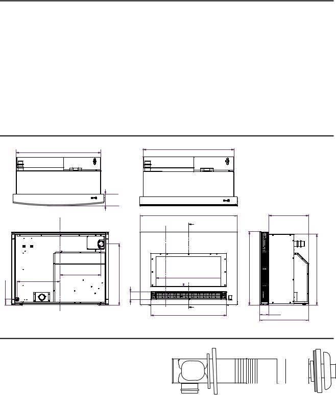
Dimensions
33 3/16 (842)
4 15/16 (126)
|
FLUE CONNECTION |
5/16 (542 - 592) |
|
|
1/42(57) |
14 7/8 (378) |
5/1621 - 23 |
|
|
15 3/4 (400) |
(71)15/16 |
|||
GAS CONNECTION |
||||
|
|
|
||
|
|
|
2 |
33 3/16 (842) |
35 7/16 (900)
B
(274)13/16 
 23 5/8 (600) 10

B
27 9/16 (700)
|
14 1/2 (369) |
26 3/4 (679) |
25 13/16 (655) |
|
3 5/16 (84) |
|
17 13/16 (453) |
Flue Manifolds
See the installation instructions for the parts list of the vent kit.
The “A” Vent Kit is included with the appliance. The following flue manifold sizes are available:
|
Name |
Kit No. |
fits walls |
|
|
|
|
|
|
A |
Vent Kit |
FOT-203 |
4 1/3 - 9 1/2 inch (110 - 240 mm) |
|
|
|
|
|
|
B |
Vent Kit |
FOT-204 |
9 1/2 - 15 3/4 inch (240 - 400 mm) |
|
|
|
|
|
|
|
|
Rinnai Corporation RHFE-750ETR |
5 |
|
Operating Instructions
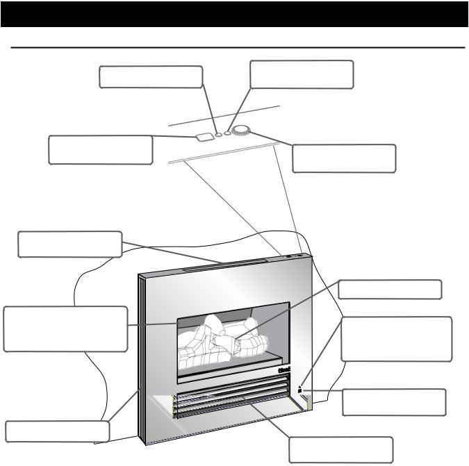
Front Panel
TIMER INDICATOR |
OPERATION INDICATOR |
FAULT CODE DISPLAY
ON/OFF BUTTON
CONTROL PANEL
OVERHEAT
DISCHARGE VENT
|
LOG SET |
TEMPERED GLASS IN THE |
|
FRONT PANEL |
BLOCKAGE INDICATOR |
CERAMIC GLASS PANEL AT |
for FILTERS (flashes red) |
THE COMBUSTION CHAMBER |
for WARM AIR DISCHARGE |
|
(glows red) |
|
REMOTE CONTROL |
|
RECEIVER WINDOW |
ROOM AIR RETURN |
|
|
LOUVER, WARM |
|
AIR DISCHARGE |
Front Panel
(features are the same for flat and curved models)
|
Front Panel Models |
|
|
|
Description |
|
Part Number |
|
|
|
|
|
Flat Metal - Black Front |
|
R2700 |
|
|
|
|
|
Flat Metal - Stainless Steel Front |
|
R2701 |
|
|
|
|
|
Radius (curved) Glass - Silver Front |
|
R2702 |
|
|
|
|
|
Radius (curved) Glass - Black Front |
|
R2703 |
|
|
|
|
6 |
Rinnai Corporation RHFE-750ETR |
||
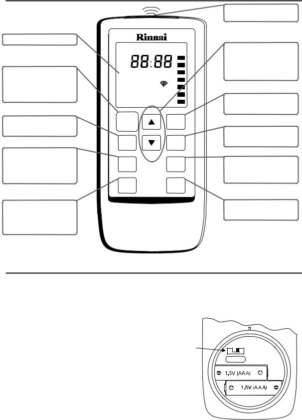
Remote Control Features
|
|
|
|
INFRA RED |
|
|
|
|
|
EMITTER |
|
DISPLAY |
|
|
|
|
|
|
Lock OverrideAuto OffFlame |
UP and DOWN |
|||
|
AM |
|
|
BUTTONS |
|
|
PM |
|
|
Changes temperature, |
|
STANDBY / ON |
TemperatureTime |
flame level, or time |
|||
BUTTON |
Clock Set |
|
|
|
|
Stops and operates the |
|
|
|
||
Timer 1Set |
ON |
OFF |
|
||
heater remotely |
TIMER 1 BUTTON |
||||
Timer 2Set |
ON |
OFF |
|||
|
Sets timer program 1 |
||||
|
|
|
|
||
FLAME BUTTON |
STANDBY |
|
Timer 1 |
|
|
ON |
|
|
|||
Controls the flame level |
|
|
TIMER 2 BUTTON |
||
|
|
|
|||
|
Flame |
|
Timer 2 |
Sets timer program 2 |
|
AUTO OFF |
|
|
|
|
|
AUTO OFF BUTTON |
Auto |
|
|
OVERRIDE BUTTON |
|
Turns the flame off when |
|
Override |
|||
Off |
|
|
|||
the temperature setting is |
|
|
Overrides timer |
||
|
|
|
|||
reached. |
Lock |
|
Time |
operation |
|
|
|
|
|||
|
|
Set |
|
||
|
|
|
|
||
LOCK BUTTON |
|
|
|
TIME SET BUTTON |
|
Locks out control to |
|
|
|
Sets the clock and timers |
|
prevent unintended |
|
|
|
|
|
operation |
|
|
|
|
|
Remote Control Care
•Use two 1.5V AAA batteries.
•To replace batteries unscrew the battery compartment cover located on the back of the remote control counter clockwise. Ensure that the correct polarity is observed. The polarity is engraved into the battery compartment. Replace the cover by turning clockwise until a soft click is heard.
•To avoid damage from leaking batteries, remove batteries if the remote control is not going to be used for a long period.
•Some fluorescent lights may interfere with the transmission of remote control signals.
•Avoid leaving the remote control in direct sunlight.
•Do not place it close to the warm air discharge louvers.
•Avoid dropping the remote control or getting it wet.
Celsius (0)/ |
0 |
1 |
|
Fahrenheit (1) |
|||
|
O- I |
||
switch |
|
||
|
|
Rinnai Corporation RHFE-750ETR |
7 |
Sequence of Operations
The combustion fan will run for several seconds before ignition to purge the combustion chamber of any gas.
If the front burner fails to ignite the appliance will turn off and fault code 11 will be displayed. If the rear burner fails to ignite the appliance will turn off and make another attempt to ignite. If this second attempt fails, the appliance will automatically turn off and fault code 11 will be displayed. This may occur when using the appliance for the first time or if it has not been used for a while. Try operating the appliance again.
The appliance may make noises after ignition or extinction of the flame. This is normal and is due to the thermal expansion or contraction of its components.
If the ON/OFF or the STANDBY/ON button is pressed immediately after the flame has been extinguished, the appliance will delay ignition for about 1 minute.
The normal ignition sequence is as follows:
1.When the ON/OFF or the STANDBY/ON button is pressed the Operation Indicator LED will glow red and the combustion fan will rotate to purge the combustion chamber.
2.Electric ignitor operates.
3.Gas is allowed to flow to the pilot when a spark is sensed.
4.When the pilot flame is established gas will flow to the front burners and then to the rear burners.
5.When all burners are established the appliance will automatically maintain the temperature setting.
NOTE: The appliance will wait until the heat exchanger is warmed up before discharging air. This ensures that any discharge air will be warm and not cold.
Basic Fireplace Operations
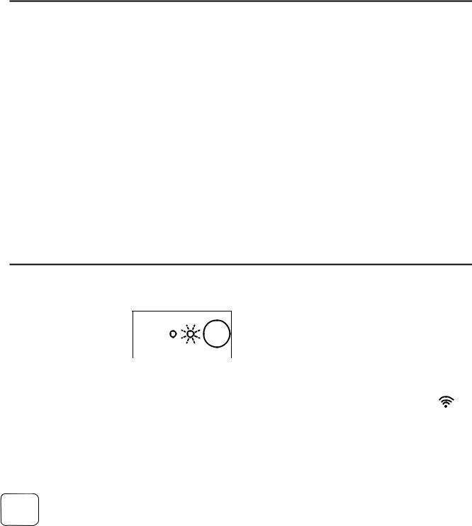
Turning ON and OFF
The Operation Indicator will glow red when the appliance is ON.
The appliance will turn ON - |
|
|
|
|
and attempt ignition: |
|
|
|
|
|
|
|
|
|
• when you press the ON/ |
|
|
|
|
|
|
|
|
|
|
|
|
|
|
OFF button on the |
Operation |
|
Indicator |
|
|
||||
appliance panel while the |
|
|
|
|
appliance is OFF. |
|
|
|
|
•when you press the STANDBY/ON button on the remote control while the appliance is in STANDBY.
•at the TIMER setting after you have activated the TIMER and while the appliance is in STANDBY.
Pressing the STANDBY/ON button on the remote control while the appliance is ON will put the
appliance in STANDBY mode, extinguishing all flames and cause the Operation Indicator to glow green.
Pressing the ON/OFF button while the appliance is ON or in STANDBY will turn the appliance OFF.
Remote Control Operation
The remote control emits an infrared (IR) signal and must be aimed at the receiver located to the right of the warm air discharge louvers. The normal operating range is about 16 feet (4.9 m) with an angle of about 40 degrees to the horizontal. This range will vary depending on the position of the installation and the strength of the remote control batteries.
Signal transmissions are confirmed by
• a brief illumination of the Transmission Signal Indicator on the Remote Display
•a flash by the Remote Control Receiver to the right of the louvers
•a beep from the appliance
The remote control transmits information whenever a button is pressed except as follows:
•when the lock function is activated
•when setting the timers, timer information is transmitted only when the “TIME SET” button is pressed
8 |
Rinnai Corporation RHFE-750ETR |
Basic Fireplace Operations
Adjusting the Temperature
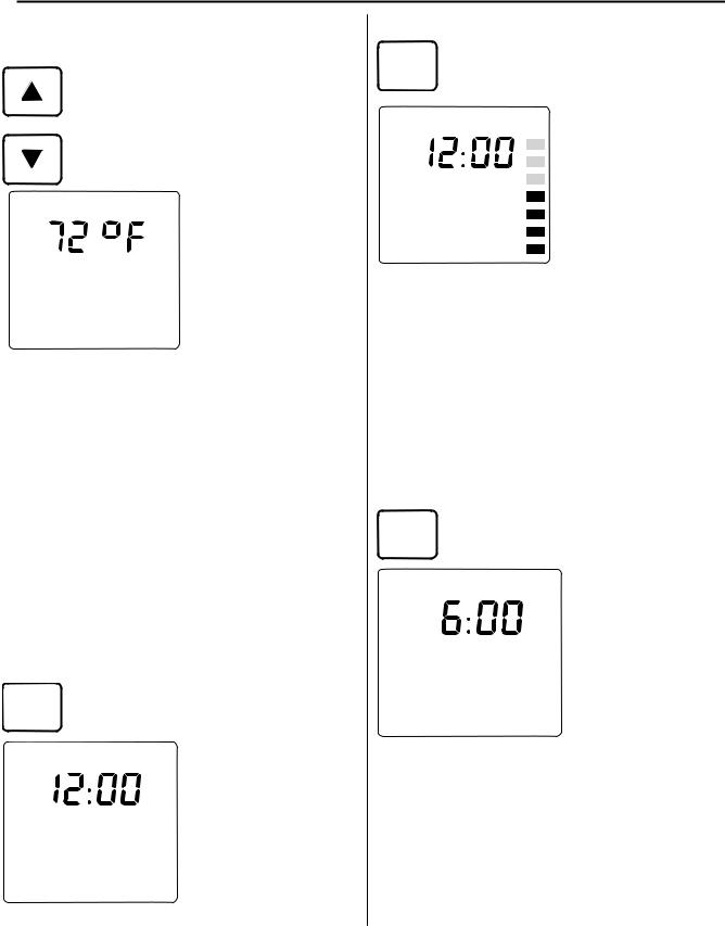
Pressing the UP and DOWN buttons will change the temperature setting by 2 degree (F) increments. The display will show “Temperature” and the new temperature as confirmation.
The temperature can be set to:
• L (Low) - burner is on minimum combustion
• 60° F - 80° F in two degree increments
Temperature |
• H (High) - burner is |
on maximum combustion |
To use Celsius scale, open the battery compartment and move the switch toward “0”.
The temperatures 16-26° C are available in one degree increments. To return to Fahrenheit scale move the switch toward “1”.
Obstruction of Warm Air Discharge
Obstructing the louvers for the warm air discharge will cause the appliance to operate inefficiently.
When an obstruction is detected the Blockage Indicator LED above the Receiver Window will glow red and combustion reduces to front burner, low operation only.
To restore normal operation, remove the obstruction, turn the appliance OFF and then ON.
Lock Function
Pressing the LOCK button will cause all Lock functions of the remote control to be locked
except for the STANDBY/ON button.
Lock |
The remote control |
display will show the word |
|
AM |
“Lock” in the top left |
|
corner. |
Time |
To cancel the Lock |
|
function press down and |
|
hold the LOCK button for |
|
3 seconds. |
Flame Function
Press the FLAME button to control the flame Flame level. There are seven levels of flame
available.
Flame
AM
Time
flame automatically.
The display will show the word “Flame” and a series of short bars (one for each flame level).
Use the UP or DOWN buttons to select the desired flame level.
Pressing the FLAME button again will allow the appliance to control the
If the room temperature reaches 104° F (40° C) while the flame function is on then the appliance will turn off automatically as a safety precaution.
The FLAME function is not available during TIMER operation.
Auto Off Function
When the appliance is not in AUTO OFF mode and the room temperature reaches the temperature
setting the appliance will reduce the gas flow and maintain the flame on the lowest flame level. The temperature may continue to rise even on this low setting. If the
|
temperature reaches |
Auto Off |
104° F (40° C) then the |
AM |
appliance will |
automatically shut down |
|
Time |
with fault code 16. |
In AUTO OFF mode the |
|
|
gas flow will be reduced |
|
to pilot operation with no |
|
visible flame when the |
|
temperature setting is |
|
reached. To enter this |
mode press the AUTO OFF button. The words “Auto Off” will be displayed above the time. To exit this mode press the AUTO OFF again.
Whether this mode is on or off, the appliance will attempt to maintain the temperature setting.
Rinnai Corporation RHFE-750ETR |
9 |
Timers
Programming the clock and timers
The clock must be set before the timers will operate. The temperature setting during timer operation is the temperature last used when the appliance was on.
During the steps below, if no button is pressed for 90 seconds then the screen will return to the current time display.
1. Press the TIME SET button. The display will show the words “Clock Set” and “AM 12:00” or the time.
2. Use the UP or DOWN buttons to set the desired clock time.
NOTE: If you do not want to set the timers now then press the TIME SET button five more times to finish setting the clock.
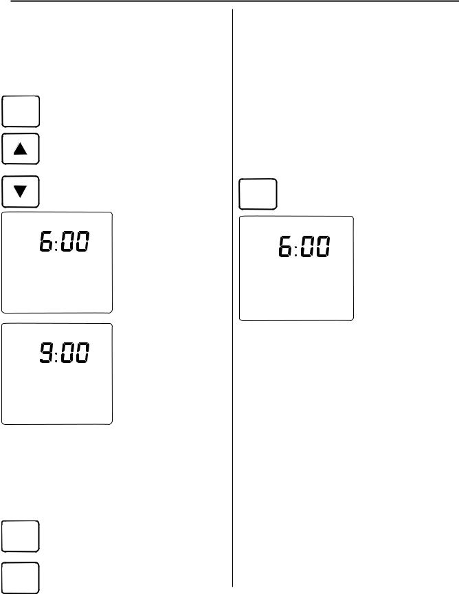
3. Press the TIME SET button. “Timer 1 Set ON” and “AM 6:00” or the last programmed time
will be displayed. Use the
UP or DOWN buttons to
set the desired on time. When finished press the TIME SET button.
4. “Timer 1 Set OFF” and “AM 9:00” or the last programmed time will be displayed. Use the UP or DOWN buttons to set the
desired off time. When
finished press the TIME
SET button.
5. To set Timer 2 repeat steps 3 and 4. If finished press the TIME SET button two more times to complete setting the clock
One or both timers can be used. To allow
Timer 1 the appliance to operate during the preprogrammed times press the TIMER 1 and/
or TIMER 2 button. The display will briefly show the “on” and “off” times for each timer.
Timer 2 If the current time is outside of the programmed times then the appliance will
go into standby mode and the Timer Indicator will glow green.
To turn the timers off press the appropriate timer button again. If the appliance was on, it will return to standby mode and the Operation Indicator will glow green.
The Timer Indicator will not display if both timers are turned off.
Using the Override
This function is used to manually override Override Timer programmed operation.
If the appliance is operating in Timer mode then pressing OVERRIDE will turn the it OFF and cause the
Time word “Override” to be displayed for 10
seconds.
If the appliance is in Timer mode but outside of the programmed time
for operation then pressing OVERRIDE will turn the appliance ON.
OVERRIDE does not change the programmed times.
Pre-heat
The appliance may operate up to one hour before the programmed ON time in order to allow the room to reach the desired temperature by the programmed ON time. The pre-heat time (how long before the programmed ON time that the appliance will provide heat) is determined by the difference between the temperature setting and the room temperature one hour before the programmed ON time.
10 |
Rinnai Corporation RHFE-750ETR |

Care and Maintenance
Maintenance
Repairs should be performed by a qualified service technician. The appliance should be inspected annually by a qualified service agency.
More frequent cleaning may be required due to excessive lint from carpeting, bedding material, etc. It is imperative that control compartments, burners, and circulating air passage ways of the appliance be kept clean.
When the appliance has cooled off, gain access by removing the front panel, combustion chamber glass panel, and ceramic logs. Refer to the Parts List and the sections Cleaning Combustion Chamber Glass and Final Assembly for disassembly / assembly instructions. Vacuum, use pressurized air, and then vacuum again to remove dust from the burners, compartments, and convection fan.
Any filter or guard removed for servicing the appliance must be replaced prior to operating the appliance.
The vent should be inspected annually for blockages or damage.
Motors are permanently lubricated and do not need periodic lubrication. Keep fan and motor free of dust and dirt by cleaning annually.
Verify proper operation after servicing.
Filters
This appliance has two filters which are behind the louvers on either side of the heater. The louvers are hinged to allow access to the filters.
Dirty filters reduce the air flow and the appliance’s
ability to produce heat. The filters should be cleaned once a week during the heating season. If the filters become blocked the blockage indicator will flash red. The filters should be cleaned whenever the blockage indicator flashes red. If not cleaned the appliance may turn off and display fault code 14 (overheat) on the control panel display.
To clean the filters, the appliance should be OFF and cool. Open the louver by pushing inward and releasing. Slide the filter upwards until the bottom tab clears the lower retaining slot. Then slide the filter down and away to remove. Clean the filter using a soft dry cloth or vacuum.
Visual Inspection of Flame
Check that the pilot and burner flames are operating normally.
If flames appear either very short or very long and streaky or are producing smoke or soot deposits then there may be a problem with the appliance or gas supply.
The appliance should not be used if you suspect there is a problem. Call a qualified service technician to inspect the appliance.
The burners are designed to produce two rows of yellow flame but not smoke or soot.
NORMAL
|
ABNORMAL |
Rinnai Corporation RHFE-750ETR |
11 |
Care and Maintenance
The pilot flame should be blue and extend over the flame rod from half to three-fourths of its length. It should not be long, streaky, or yellow.
CORRECT PILOT FLAME APPEARANCE
Over time combustion products may leave a film on the combustion chamber glass. Continued use of the appliance may permanently stain the glass. If filming occurs, this glass panel needs to be removed, cleaned, and installed only by a qualified service technician.
 WARNING
Do not clean glass when hot.
Do not clean glass with abrasive cleaners.
unhook top
Front Panel
rotate outward first
Care of Exterior
Clean exterior as required using non-abrasive and non-solvent cleaner. Ensure exterior is completely dry before operating.
12 |
Rinnai Corporation RHFE-750ETR |
Cleaning1. Open theCombustionside louvers andChamberon each sideGlassremove
 Loading...