

Page 1

CÓPIA NÃO CONTROLADA
CÓPIA NÃO CONTROLADA
M035/M036
SERVICE MANUAL
004774MIU
Page 2

CÓPIA NÃO CONTROLADA
CÓPIA NÃO CONTROLADA
Page 3

CÓPIA NÃO CONTROLADA
CÓPIA NÃO CONTROLADA
SERVICE MANUAL
M035/M036
Page 4

CÓPIA NÃO CONTROLADA
CÓPIA NÃO CONTROLADA
Page 5

CÓPIA NÃO CONTROLADA
CÓPIA NÃO CONTROLADA
M035/M036
SERVICE MANUAL
004774MIU
Page 6

CÓPIA NÃO CONTROLADA
CÓPIA NÃO CONTROLADA
Page 7

CÓPIA NÃO CONTROLADA
CÓPIA NÃO CONTROLADA
It is the reader's responsibility when discussing the information contained
within this document to maintain a level of confidentiality that is in the best
interest of Ricoh Americas Corporation and its member companies.
NO PART OF THIS DOCUMENT MAY BE REPRODUCED IN ANY
FASHION AND DISTRIBUTED WITHOUT THE PRIOR
PERMISSION OF RICOH AMERICAS CORPORATION.
All product names, domain names or product illustrations, including
desktop images, used in this document are trademarks, registered
trademarks or the property of their respective companies.
They are used throughout this book in an informational or editorial fashion
only and for the benefit of such companies. No such use, or the use of
any trade name, or web site is intended to convey endorsement or other
affiliation with Ricoh products.
© 2009 RICOH Americas Corporation. All rights reserved.
Page 8

CÓPIA NÃO CONTROLADA
CÓPIA NÃO CONTROLADA
Page 9

CÓPIA NÃO CONTROLADA
CÓPIA NÃO CONTROLADA
WARNING
The Service Manual contains information
regarding service techniques, procedures,
processes and spare parts of office equipment
distributed by Ricoh Americas Corporation.
Users of this manual should be either service
trained or certified by successfully completing a
Ricoh Technical Training Program.
Untrained and uncertified users utilizing
information contained in this service manual to
repair or modify Ricoh equipment risk personal
injury, damage to property or loss of warranty
protection.
Ricoh Americas Corporation
Page 10

CÓPIA NÃO CONTROLADA
CÓPIA NÃO CONTROLADA
Page 11
CÓPIA NÃO CONTROLADA
CÓPIA NÃO CONTROLADA
LEGEND
PRODUCT
CODE
M035 -- SP C231N Aficio SP C231N SP C231N
M036 -- SP C232DN Aficio SP C232DN SP C232DN
GESTETNER LANIER RICOH SAVIN
COMPANY
DOCUMENTATION HISTORY
REV. NO. DATE COMMENTS
*
05/2009 Original Printing
Page 12

CÓPIA NÃO CONTROLADA
CÓPIA NÃO CONTROLADA
Page 13

CÓPIA NÃO CONTROLADA
CÓPIA NÃO CONTROLADA
M035/M036
TABLE OF CONTENTS
PRODUCT INFORMATION
1. PRODUCT INFORMATION.......................................................... 1-1
1.1 SPECIFICATIONS ..................................................................................... 1-1
1.2 MACHINE OVERVIEW .............................................................................. 1-2
1.2.1 COMPONENT LAYOUT ................................................................... 1-2
1.2.2 PAPER PATH ................................................................................... 1-3
1.2.3 DRIVE LAYOUT................................................................................ 1-4
1.3 MACHINE CONFIGURATION ................................................................... 1-6
1.4 GUIDANCE FOR THOSE WHO ARE FAMILIAR WITH
PREDECESSOR PRODUCTS ................................................................. 1-7
INSTALLATION
2. INSTALLATION ........................................................................... 2-1
2.1 INSTALLATION REQUIREMENTS............................................................ 2-1
2.1.1 ENVIRONMENT ............................................................................... 2-1
2.1.2 MACHINE LEVEL ............................................................................. 2-2
2.1.3 MACHINE SPACE REQUIREMENT................................................. 2-2
2.1.4 POWER REQUIREMENTS............................................................... 2-3
2.1.5 INSTALLATION PROCEDURE......................................................... 2-3
PREVENTIVE MAINTENANCE
3. PREVENTIVE MAINTENANCE ................................................... 3-1
3.1 PREVENTIVE MAINTENANCE ................................................................. 3-1
SM i M035/M036
Page 14

CÓPIA NÃO CONTROLADA
CÓPIA NÃO CONTROLADA
REPLACEMENT AND ADJUSTMENT
4. REPLACEMENT AND ADJUSTMENT ........................................ 4-1
4.1 BEFORE YOU START............................................................................... 4-1
4.2 SPECIAL TOOLS....................................................................................... 4-2
4.3 EXTERIOR COVERS................................................................................. 4-3
4.3.1 REAR COVER .................................................................................. 4-3
4.3.2 OPERATION PANEL ........................................................................ 4-4
4.3.3 RIGHT COVER ................................................................................. 4-5
4.3.4 LEFT COVER ................................................................................... 4-6
4.3.5 FRONT COVER UNIT ...................................................................... 4-7
4.4 LASER OPTICS ......................................................................................... 4-9
4.4.1 CAUTION DECAL LOCATION.......................................................... 4-9
4.4.2 LASER OPTICS HOUSING UNIT................................................... 4-10
After replacing the laser optics housing unit....................................... 4-12
4.5 AIO CARTRIDGE..................................................................................... 4-14
4.5.1 AIO CARTRIDGE (ALL IN ONE CARTRIDGE)............................... 4-14
4.5.2 BLACK AIO MOTOR....................................................................... 4-15
4.5.3 COLOR AIO MOTOR...................................................................... 4-18
4.6 IMAGE TRANSFER ................................................................................. 4-19
4.6.1 IMAGE TRANSFER BELT UNIT..................................................... 4-19
After replacing the image transfer belt unit......................................... 4-20
4.6.2 ITB (IMAGE TRANSFER BELT) CLEANING UNIT......................... 4-21
4.6.3 AGITATOR MOTOR ....................................................................... 4-22
4.6.4 ITB (IMAGE TRANSFER BELT) CONTACT MOTOR..................... 4-23
4.6.5 ITB (IMAGE TRANSFER BELT) CONTACT SENSOR................... 4-24
4.6.6 TM (TONER MARK) SENSOR BASE............................................. 4-25
4.6.7 WASTE TONER BOTTLE SET SENSOR....................................... 4-26
4.6.8 WASTE TONER OVERFLOW SENSOR ........................................ 4-27
4.7 PAPER TRANSFER................................................................................. 4-28
4.7.1 TRANSFER UNIT ........................................................................... 4-28
4.7.2 TRANSFER ROLLER ..................................................................... 4-29
4.7.3 REGISTRATION ROLLER.............................................................. 4-31
Reassembling the registration roller unit ............................................ 4-31
4.7.4 REGISTRATION SENSOR ............................................................. 4-32
M035/M036 ii SM
Page 15

4.7.5 REGISTRATION CLUTCH.............................................................. 4-33
CÓPIA NÃO CONTROLADA
CÓPIA NÃO CONTROLADA
4.8 IMAGE FUSING ....................................................................................... 4-34
4.8.1 FUSING UNIT ................................................................................. 4-34
4.8.2 FUSING LAMP................................................................................ 4-36
When Reinstalling the Fusing Lamp................................................... 4-36
4.8.3 TRANSPORT/FUSING MOTOR ..................................................... 4-37
4.9 PAPER FEED .......................................................................................... 4-38
4.9.1 PAPER FEED CLUTCH.................................................................. 4-38
4.9.2 PAPER FEED ROLLER .................................................................. 4-39
4.9.3 SEPARATION PAD ........................................................................ 4-40
4.9.4 PAPER END SENSOR ................................................................... 4-41
4.10 PAPER EXIT ...................................................................................... 4-42
4.10.1 PAPER EXIT ROLLER .............................................................. 4-42
When reinstalling the paper exit roller ................................................ 4-43
4.10.2 PAPER EXIT SENSOR ............................................................. 4-44
4.11 ELECTRICAL COMPONENTS........................................................... 4-45
4.11.1 CONTROLLER BOARD ............................................................ 4-45
4.11.2 EGB (ENGINE BOARD) ............................................................ 4-46
When installing the new EGB ............................................................. 4-47
4.11.3 INTERLOCK SWITCHES .......................................................... 4-48
4.11.4 FUSING FAN MOTOR .............................................................. 4-49
4.11.5 LSU FAN MOTOR..................................................................... 4-50
4.11.6 ID CHIP BOARD ....................................................................... 4-51
4.11.7 PSU ........................................................................................... 4-52
Fuse ................................................................................................... 4-54
4.11.8 HIGH VOLTAGE POWER SUPPLY BOARD ............................ 4-54
4.11.9 TEMPERATURE/HUMIDITY SENSOR ..................................... 4-55
4.11.10 DUPLEX MOTOR (M036 ONLY).............................................. 4-56
4.11.11 EEPROM .................................................................................. 4-57
SYSTEM MAINTENANCE REFERENCE
5. SYSTEM MAINTENANCE REFERENCE .................................... 5-1
5.1 SERVICE PROGRAM................................................................................ 5-1
5.1.1 OVERVIEW....................................................................................... 5-1
5.2 CONFIGURATION AND TEST PAGE INFORMATION ............................. 5-2
SM iii M035/M036
Page 16

5.2.1 OVERVIEW....................................................................................... 5-2
CÓPIA NÃO CONTROLADA
CÓPIA NÃO CONTROLADA
To Print the Configuration Page from the Machine............................... 5-2
To Print the Configuration Page from the SOM .................................... 5-2
To Print the Test Page from the Machine............................................. 5-2
To Print the Test Page from the SOM .................................................. 5-2
5.2.2 ERROR LOG .................................................................................... 5-3
5.2.3 COUNTER AND COVERAGE .......................................................... 5-4
Configuration Page............................................................................... 5-4
Test Page............................................................................................. 5-5
5.3 FIRMWARE UPDATING ............................................................................ 5-6
5.3.1 PRINTER MODEL ............................................................................ 5-6
Controller Firmware.............................................................................. 5-6
Engine Firmware .................................................................................. 5-8
5.3.2 BOOT LOADER FIRMWARE............................................................ 5-9
TROUBLESHOOTING
6. TROUBLESHOOTING ................................................................. 6-1
6.1 TROUBLESHOOTING GUIDE................................................................... 6-1
6.2 IMAGE PROBLEMS................................................................................... 6-2
6.2.1 OVERVIEW....................................................................................... 6-2
6.2.2 CHECKING A SAMPLE PRINTOUT................................................. 6-3
Printer Driver Setting for Printing a Sample.......................................... 6-3
M035/M036 SERVICE MANUAL APPENDICES
SEE M035/M036 SERVICE MANUAL APPENDICES SECTION FOR DETAILED TABLE
OF CONTENTS
G849 PAPER FEED UNIT TK1010
SEE SECTION G849 FOR DETAILED TABLE OF CONTENTS
M035/M036 iv SM
Page 17
CÓPIA NÃO CONTROLADA
CÓPIA NÃO CONTROLADA
PRODUCT INFORMATION
APPENDIX: SPECIFICATIONS
INSTALLATION
APPENDIX: PREVENTIVE MAINTENANCE
G849 Paper Feed Unit TK1010
PREVENTIVE MAINTENANCE
APPENDIX: TROUBLESHOOTING GUIDE
REPLACEMENT AND ADJUSTMENT
APPENDIX: SP MODE TABLES
TAB
POSITION 1
TAB
POSITION 2
TAB
POSITION 3
TAB
POSITION 4
SYSTEM MAINTENANCE REFERENCE
APPENDIX: MACHINE SWAP
TROUBLESHOOTING
TAB
POSITION 5
TAB
POSITION 6
TAB
POSITION 7
TAB
POSITION 8
Page 18

CÓPIA NÃO CONTROLADA
CÓPIA NÃO CONTROLADA
Page 19

CÓPIA NÃO CONTROLADA
CÓPIA NÃO CONTROLADA
Read This First
Safety Notices
Important Safety Notices
Prevention of Physical Injury
1. Before disassembling or assembling parts of the printer and peripherals, make sure
that the printer power cord is unplugged.
2. The wall outlet should be near the printer and easily accessible.
3. If any adjustment or operation check has to be made with exterior covers off or open
while the main switch is turned on, keep hands away from electrified or mechanically
driven components.
4. The printer drives some of its components when it completes the warm-up period. Be
careful to keep hands away from the mechanical and electrical components as the
printer starts operation.
5. The inside and the metal parts of the fusing unit become extremely hot while the printer
is operating. Be careful to avoid touching those components with your bare hands.
Health Safety Conditions
Toner is non-toxic, but if you get it in your eyes by accident, it may cause temporary eye
discomfort. Try to remove with eye drops or flush with water as first aid. If unsuccessful, get
medical attention.
Observance of Electrical Safety Standards
The printer and its peripherals must be serviced by a customer service representative who
has completed the training course on those models.
Safety and Ecological Notes for Disposal
1. Do not incinerate toner bottles or used toner. Toner dust may ignite suddenly when
exposed to an open flame.
2. Dispose of used toner, the maintenance unit which includes developer or the organic
photoconductor in accordance with local regulations. (These are non-toxic supplies.)
3. Dispose of replaced parts in accordance with local regulations.
Page 20
CÓPIA NÃO CONTROLADA
CÓPIA NÃO CONTROLADA
To prevent a fire or explosion, keep the printer away from flammable liquids, gases,
and aerosols. A fire or an explosion might occur.
Laser Safety
The Center for Devices and Radiological Health (CDRH) prohibits the repair of laser-based
optical units in the field. The optical housing unit can only be repaired in a factory or at a
location with the requisite equipment. The laser subsystem is replaceable in the field by a
qualified Customer Engineer. The laser chassis is not repairable in the field. Customer
engineers are therefore directed to return all chassis and laser subsystems to the factory or
service depot when replacement of the optical subsystem is required.
Use of controls, or adjustment, or performance of procedures other than those
specified in this manual may result in hazardous radiation exposure.
WARNING
WAR NING:
Turn off the main switch before attempting any of the procedures in the Laser Optics
Housing Unit section. Laser beams can seriously damage your eyes.
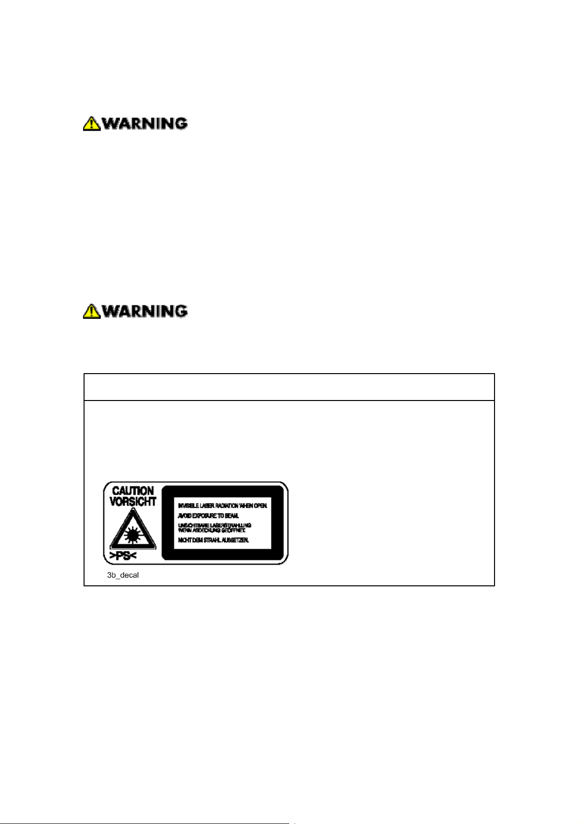
CAUTION MARKING:
Page 21
CÓPIA NÃO CONTROLADA
CÓPIA NÃO CONTROLADA
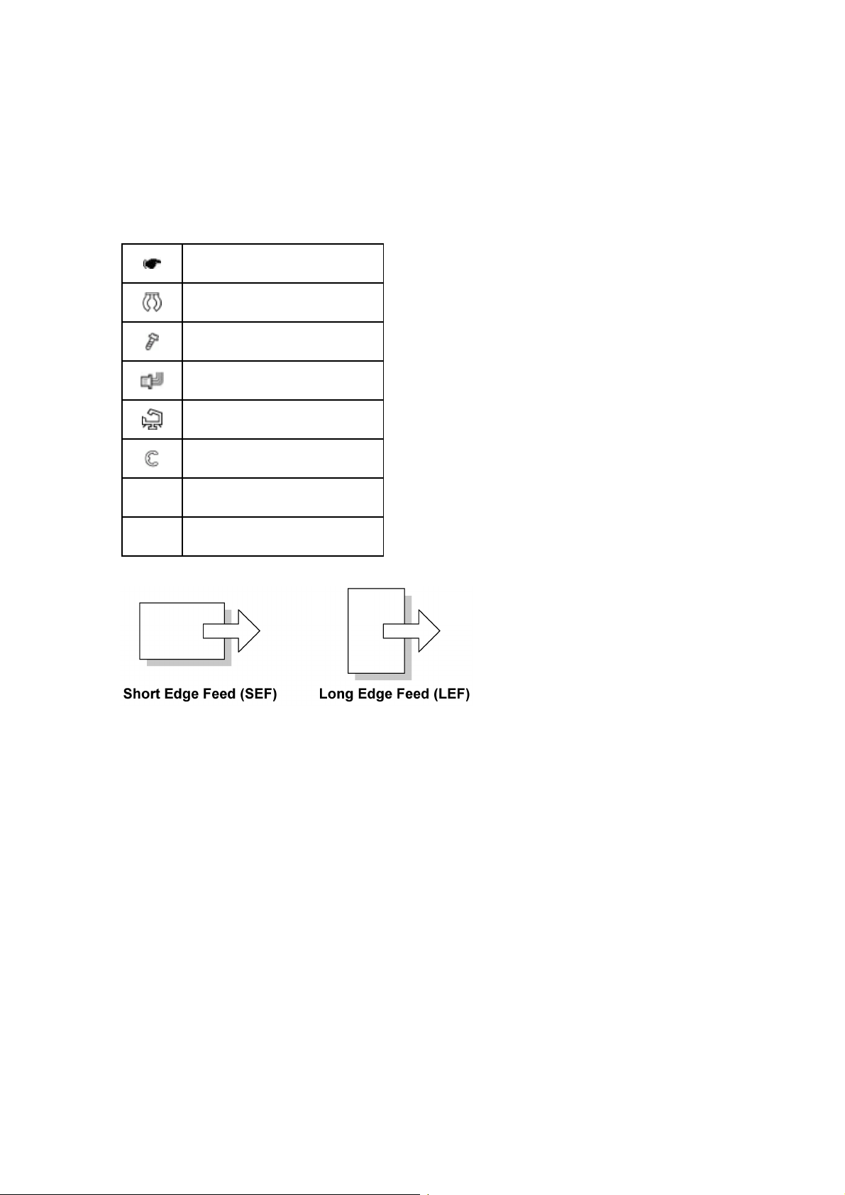
Symbols, Abbreviations and Trademarks
This manual uses several symbols and abbreviations. The meaning of those symbols and
abbreviations are as follows:
See or Refer to
Clip ring
Screw
Connector
Clamp
E-ring
SEF Short Edge Feed
LEF Long Edge Feed
Trademarks
Microsoft®, Windows®, and MS-DOS® are registered trademarks of Microsoft Corporation
in the United States and /or other countries.
PostScript
PCL
Ethernet
PowerPC
Other product names used herein are for identification purposes only and may be
trademarks of their respective companies. We disclaim any and all rights involved with
®
is a registered trademark of Adobe Systems, Incorporated.
®
is a registered trademark of Hewlett-Packard Company.
®
is a registered trademark of Xerox Corporation.
®
is a registered trademark of International Business Machines Corporation.
those marks.
Page 22

CÓPIA NÃO CONTROLADA
CÓPIA NÃO CONTROLADA
Page 23

CÓPIA NÃO CONTROLADA
CÓPIA NÃO CONTROLADA
PRODUCT INFORMATION
REVISION HISTORY
Page Date Added/Updated/New
None
Page 24

CÓPIA NÃO CONTROLADA
CÓPIA NÃO CONTROLADA
Page 25

1. PRODUCT INFORMATION
CÓPIA NÃO CONTROLADA
CÓPIA NÃO CONTROLADA
1.1 SPECIFICATIONS
See "Appendices" for the following information:
Specifications
Product
Information
"General Specifications
"Supported Paper Sizes
"
"
SM 1-1 M035/M036
Page 26
Machine Overview
CÓPIA NÃO CONTROLADA
CÓPIA NÃO CONTROLADA
1.2 MACHINE OVERVIEW
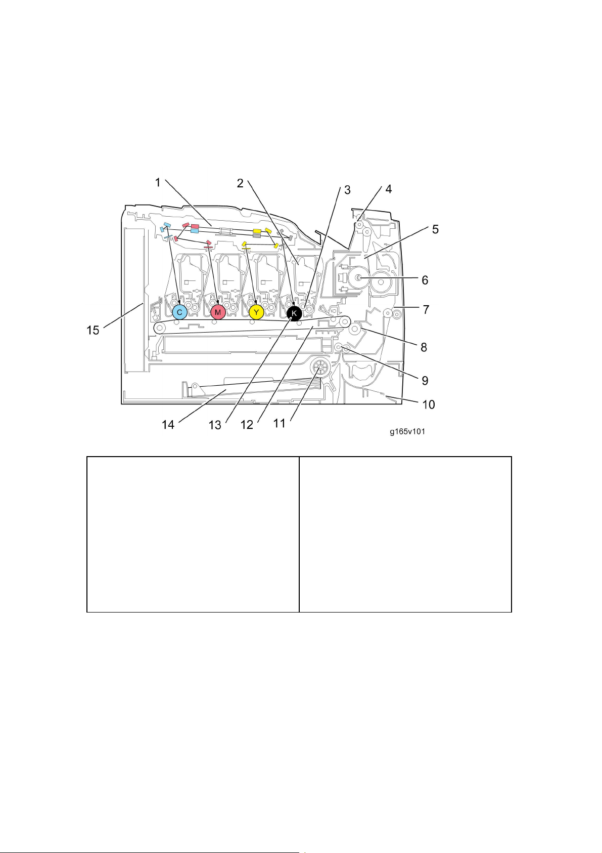
1.2.1 COMPONENT LAYOUT
1. Laser Optics Housing Unit
2. Print Cartridge (AIO)
3. Development Roller (AIO)
4. Paper Exit
5. Fusing Unit
6. Fusing Lamp
7. Duplex Path
8. Transfer Roller
9. Registration Roller
10. By-pass
11. Paper Feed Roller
12. ITB (Image Transfer Belt) Unit
13. OPC (AIO)
14. Tray 1
15 EGB/Controller
M035/M036 1-2 SM
Page 27
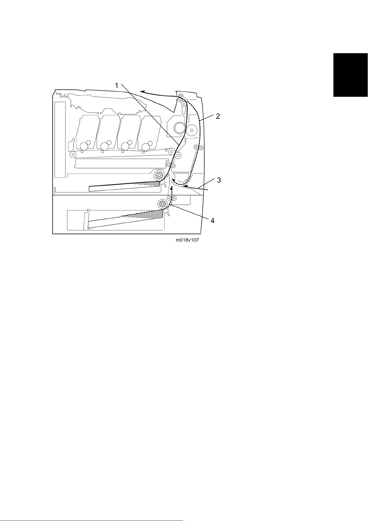
1.2.2 PAPER PATH
CÓPIA NÃO CONTROLADA
CÓPIA NÃO CONTROLADA
Machine Overview
Product
Information
1. Paper path from tray 1
2. Duplex path (M036 only)
3. By-pass tray
4. Paper path from tray 2 (optional)
SM 1-3 M035/M036
Page 28
Machine Overview
CÓPIA NÃO CONTROLADA
CÓPIA NÃO CONTROLADA
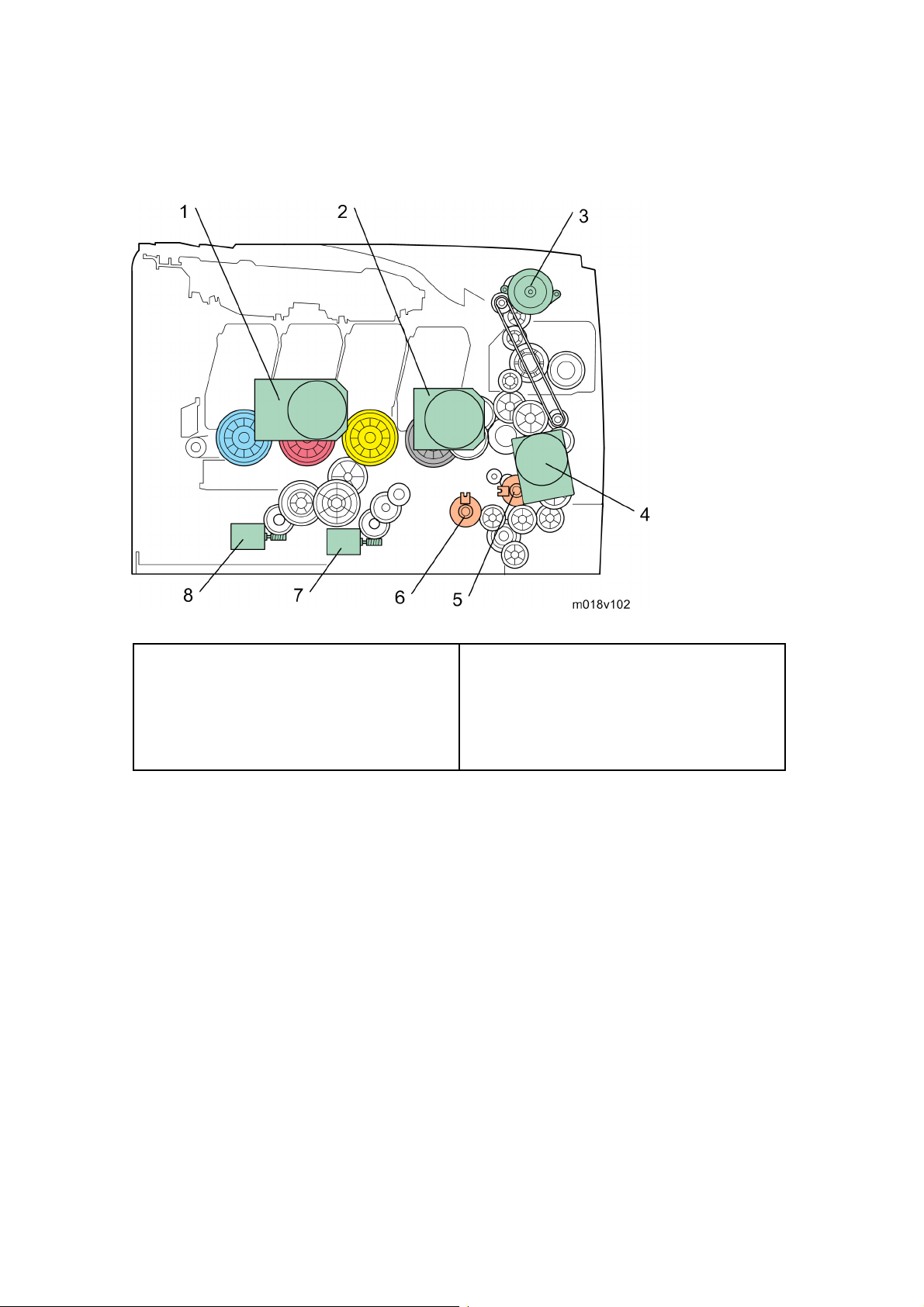
1.2.3 DRIVE LAYOUT
1. Color AIO Motor
2. Black AIO Motor
3. Duplex Motor (M036 only)
4. Transport/Fusing Motor
Color AIO Motor:
This drives the color AIOs (Cyan, Magenta and Yellow)
Black AIO Motor:
This drives the black AIO and the ITB (Image Transfer Belt).
Duplex Motor (M036 only):
This drives the paper exit roller and the duplex roller.
Transport/Fusing Motor:
This drives the fusing unit, paper feed roller, registration roller and paper exit roller via
the paper feed clutch, registration clutch and gears.
5. Registration Clutch
6. Paper Feed Clutch
7. Agitator Motor
8. ITB (Image Transfer Belt) Contact Motor
M035/M036 1-4 SM
Page 29

Machine Overview
CÓPIA NÃO CONTROLADA
CÓPIA NÃO CONTROLADA
Registration Clutch:
This transfers drive from the transport/ fusing motor to the registration roller.
Paper Feed Clutch:
This transfers drive from the transport/ fusing motor to the paper feed roller.
Agitator Motor:
This moves the agitators in the waste toner bottle.
ITB Contact Motor:
This moves the ITB into contact with and away from the color OPCs.
Product
Information
SM 1-5 M035/M036
Page 30
Machine Configuration
CÓPIA NÃO CONTROLADA
CÓPIA NÃO CONTROLADA
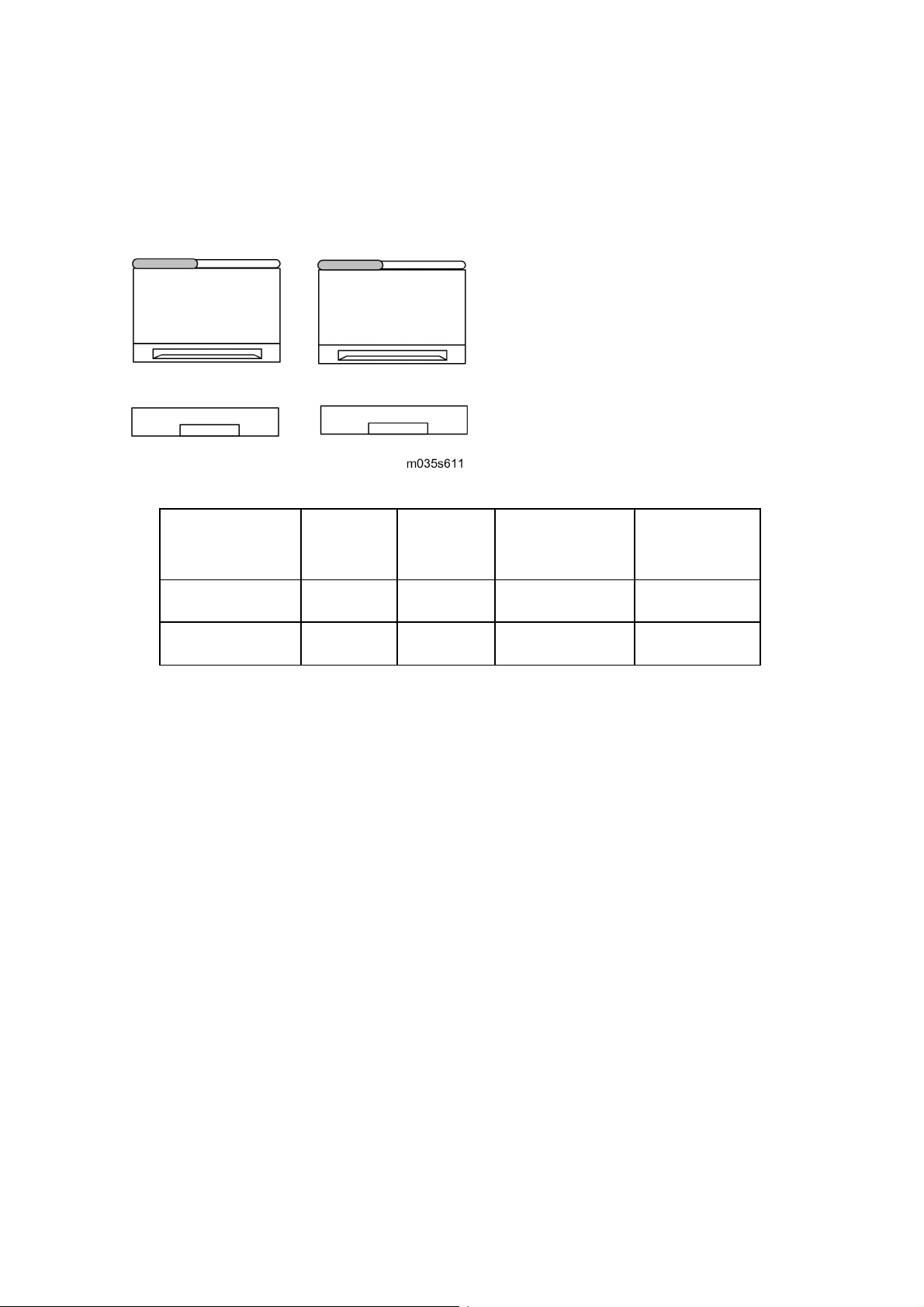
1.3 MACHINE CONFIGURATION
M035 M036
Models
Duplex
Unit
M035 Manual Y 500x1 Y
M036 Auto Y 500x1 Y
Optional
Memory
Optional
Tray (G849)
PCL
PS
M035/M036 1-6 SM
Page 31

Guidance for Those Who are Familiar with Predecessor Products
CÓPIA NÃO CONTROLADA
CÓPIA NÃO CONTROLADA
1.4 GUIDANCE FOR THOSE WHO ARE FAMILIAR
WITH PREDECESSOR PRODUCTS
The M035/M036 series models are similar to the G165/G166/G167 series. If you have
experience with those products, the following information will be of help when you read this
manual.
Different Points from Previous Products
Print Cartridge (AIO) Longer Life Print Cartridge (AIO) -
Operation Panel 2-line LCD No LCD
M035/M036 G165/G166/G167
Product
Information
SM 1-7 M035/M036
Page 32

CÓPIA NÃO CONTROLADA
CÓPIA NÃO CONTROLADA
Page 33

CÓPIA NÃO CONTROLADA
CÓPIA NÃO CONTROLADA
INSTALLATION
REVISION HISTORY
Page Date Added/Updated/New
None
Page 34

CÓPIA NÃO CONTROLADA
CÓPIA NÃO CONTROLADA
Page 35

2. INSTALLATION
CÓPIA NÃO CONTROLADA
CÓPIA NÃO CONTROLADA
2.1 INSTALLATION REQUIREMENTS
2.1.1 ENVIRONMENT
Installation Requirements
Installation
1. Temperature Range: 10°C to 32°C (50°F to 89.6°F)
2. Humidity Range: 15% to 80% RH
3. Ambient Illumination: Less than 2,000 lux (do not expose to direct sunlight)
4. Ventilation: 3 times/hr/person
5. Do not put the machine in areas that get sudden temperature changes. This includes:
Areas directly exposed to cool air from an air conditioner
Areas directly exposed to heat from a heater.
6. Do not put the machine in areas that get exposed to corrosive gas.
7. Do not install the machine at locations over 2,500 m (8,125 ft.) above sea level.
8. Put the machine on a strong, level base. (Inclination on any side must be no more than
5 mm.)
9. Do not put the machine in areas with strong vibrations.
SM 2-1 M035/M036
Page 36

Installation Requirements
CÓPIA NÃO CONTROLADA
CÓPIA NÃO CONTROLADA
2.1.2 MACHINE LEVEL
Front to back: Within 5 mm (0.2") of level
Right to left: Within 5 mm (0.2") of level
2.1.3 MACHINE SPACE REQUIREMENT
Put the printer near the power source with these clearances:
Right side [A]:
Left side [C]:
Front [B]:
Rear [D]:
Over 10 cm (4.0")
Over 70 cm (27.5")
Over 20 cm (7.9")
Over 10 cm (4.0")
M035/M036 2-2 SM
Page 37

2.1.4 POWER REQUIREMENTS
CÓPIA NÃO CONTROLADA
CÓPIA NÃO CONTROLADA
Make sure that the plug is tightly in the outlet.
Avoid multi-wiring.
Make sure that you ground the printer.
120 V, 60 Hz: More than 11 A (for North America)
Input voltage level
220 V to 240 V, 50 Hz/60 Hz: More than 6 A (for Europe/ Asia)
Permitted voltage fluctuation: 10%
Do not set anything on the power cord.
Installation Requirements
Installation
2.1.5 INSTALLATION PROCEDURE
Refer to the Quick Installation Guide for details about installing the printer.
SM 2-3 M035/M036
Page 38

CÓPIA NÃO CONTROLADA
CÓPIA NÃO CONTROLADA
Page 39

CÓPIA NÃO CONTROLADA
CÓPIA NÃO CONTROLADA
PREVENTIVE MAINTENANCE
REVISION HISTORY
Page Date Added/Updated/New
None
Page 40

CÓPIA NÃO CONTROLADA
CÓPIA NÃO CONTROLADA
Page 41

3. PREVENTIVE MAINTENANCE
CÓPIA NÃO CONTROLADA
CÓPIA NÃO CONTROLADA
3.1 PREVENTIVE MAINTENANCE
See "Appendices" for the "User Replaceable Items.”
Preventive Maintenance
Preventive
Maintenance
SM 3-1 M035/M036
Page 42

CÓPIA NÃO CONTROLADA
CÓPIA NÃO CONTROLADA
Page 43

CÓPIA NÃO CONTROLADA
CÓPIA NÃO CONTROLADA
REPLACEMENT AND ADJUSTMENT
REVISION HISTORY
Page Date Added/Updated/New
None
Page 44

CÓPIA NÃO CONTROLADA
CÓPIA NÃO CONTROLADA
Page 45

4. REPLACEMENT AND ADJUSTMENT
CÓPIA NÃO CONTROLADA
CÓPIA NÃO CONTROLADA
4.1 BEFORE YOU START
If there are printer jobs in the printer, print out all jobs in the printer buffer.
Turn off the main power switch and unplug the printer before you do the
procedures in this section.
Before You Start
&
Adjustment
Replacement
SM 4-1 M035/M036
Page 46

Special Tools
CÓPIA NÃO CONTROLADA
CÓPIA NÃO CONTROLADA
4.2 SPECIAL TOOLS
PC: Windows 2000/XP/Vista, Windows Server 2003/2003 R2, or Mac OS X.
USB cable or Crossover cable
M035/M036 4-2 SM
Page 47

4.3 EXTERIOR COVERS
CÓPIA NÃO CONTROLADA
CÓPIA NÃO CONTROLADA
Turn off the main power switch and unplug the printer before you do the
procedures in this section.
4.3.1 REAR COVER
Exterior Covers
1. Rear tray cover [A] (hooks)
2. Interface cover [B] (hooks)
3. Rear cover [C] (
x 3)
&
Adjustment
Replacement
SM 4-3 M035/M036
Page 48

Exterior Covers
CÓPIA NÃO CONTROLADA
CÓPIA NÃO CONTROLADA
4.3.2 OPERATION PANEL
1. Open the top cover [A].
2. Open the front cover [B].
3. Front harness cover [C] (
4. Operation panel [D] ( x 1, x 1)
x 1)
M035/M036 4-4 SM
Page 49

4.3.3 RIGHT COVER
CÓPIA NÃO CONTROLADA
CÓPIA NÃO CONTROLADA
1. Rear cover ( p.4-3)
Exterior Covers
2. Operation panel (
3. Right cover [A] (
Top front screw: M3x8, others: M4x10
p.4-4)
x 4)
&
Adjustment
Replacement
SM 4-5 M035/M036
Page 50

Exterior Covers
CÓPIA NÃO CONTROLADA
CÓPIA NÃO CONTROLADA
4.3.4 LEFT COVER
1. Rear cover ( p.4-3)
2. Operation panel (
3. Left cover [A] (
Top front screw: M3x8, others: M4x10
p.4-4)
x 3, hook at arrow mark)
M035/M036 4-6 SM
Page 51

4.3.5 FRONT COVER UNIT
CÓPIA NÃO CONTROLADA
CÓPIA NÃO CONTROLADA
1. Rear cover ( p.4-3)
Exterior Covers
2. Operation panel (
3. Transfer unit (
4. Right cover (
5. Close the front cover [A].
6. Remove a spring [B] (
Never remove the spring with the front cover open.
When removing the spring when it is extended, it may move in a unexpected
p.4-4)
p.4-29)
p.4-5)
x 1)
&
Adjustment
Replacement
direction and cause a slight injury.
7. Open the front cover.
8. Cover link gear unit [C] (
x 2)
SM 4-7 M035/M036
Page 52

Exterior Covers
CÓPIA NÃO CONTROLADA
CÓPIA NÃO CONTROLADA
9. Release the belt [D]
10. Front cover unit [E] (
x 4)
M035/M036 4-8 SM
Page 53

Laser Optics
CÓPIA NÃO CONTROLADA
CÓPIA NÃO CONTROLADA
4.4 LASER OPTICS
Turn off the main power switch and unplug the printer before beginning any of the
procedures in this section. Laser beams can cause serious eye injury.
4.4.1 CAUTION DECAL LOCATION
Caution decals are attached as shown below.
Be sure to turn off the main power switch and disconnect the power plug from the
power outlet before beginning any disassembly or adjustment of the laser unit.
This printer uses a class IIIb laser beam with a wavelength of 780 nm and an
output of 7 mW. The laser can cause serious eye injury.
&
Adjustment
Replacement
SM 4-9 M035/M036
Page 54

Laser Optics
CÓPIA NÃO CONTROLADA
CÓPIA NÃO CONTROLADA
4.4.2 LASER OPTICS HOUSING UNIT
1. Rear cover ( p.4-3)
2. Controller box cover (
3. Remove the controller bracket (
4. Disconnect the three harnesses from
CN301, 302 and 303 on the EGB (
5. Open the top cover [A].
p.4-46)
p.4-47)
x 3).
6. Lift up the hook [B] of the harness
guide at the rear-left frame and slide the harness guide to the right.
M035/M036 4-10 SM
Page 55

CÓPIA NÃO CONTROLADA
CÓPIA NÃO CONTROLADA
7. Remove the springs [D] (left side and right side).
8. Stoppers [C] ( x 2 each; left side and right side)
Laser Optics
9. Remove the laser optics housing unit [E] from the top cover and place it on the main
body.
Always use two hands when carrying the laser optics housing unit. Be sure
not to drop the laser optics housing unit.
&
Adjustment
Replacement
10. Take out the harnesses [F] (
SM 4-11 M035/M036
x 1).
Page 56

Laser Optics
CÓPIA NÃO CONTROLADA
CÓPIA NÃO CONTROLADA
11. Pull out the harnesses from the rear side.
12. Remove the laser optics housing unit.
After replacing the laser optics housing unit
Do the following step 4 with the front cover of the printer open.
1. Open the front cover and turn on the printer.
2. Look for the lot number [A] attached to the new laser optics housing unit. Then look for
this lot number on the information sheet (this sheet will be released separately, and will
contain lists of input data for each lot number)
Input the data for this lot number from the information sheets with steps 3 to 7
below.
M035/M036 4-12 SM
Page 57

Laser Optics
CÓPIA NÃO CONTROLADA
CÓPIA NÃO CONTROLADA
3. Open the front cover and turn on the printer.
4. Input the settings for the laser optics housing unit.
In the SOM utility, access “LSU Adjustment” inside the “SP Mode 2” tab.
Copy the corresponding LSU data inside the information sheet into the space
provided in the SOM utility.
5. Close the front cover.
6. Execute "Color Registration" in the "SP Mode 2" tab.
7. Adjust the registration settings for each tray and for the front and rear sides of the
paper with the "SP Mode 2" tab if necessary.
&
Adjustment
Replacement
SM 4-13 M035/M036
Page 58

AIO Cartridge
CÓPIA NÃO CONTROLADA
CÓPIA NÃO CONTROLADA
4.5 AIO CARTRIDGE
4.5.1 AIO CARTRIDGE (ALL IN ONE CARTRIDGE)
1. Open the top cover.
2. AIO cartridge [A]
M035/M036 4-14 SM
Page 59

AIO Cartridge
CÓPIA NÃO CONTROLADA
CÓPIA NÃO CONTROLADA
4.5.2 BLACK AIO MOTOR
1. Left cover ( p.4-6)
2. Disconnect the fusing connector [A] and remove the fusing relay harness [B] (hooks).
3. Fusing harness guide [C] (
x 2)
&
Adjustment
Replacement
SM 4-15 M035/M036
Page 60

AIO Cartridge
CÓPIA NÃO CONTROLADA
CÓPIA NÃO CONTROLADA
4. Disconnect the connectors shown by arrows in the above picture and release all
harnesses on the harness guide [D].
5. Harness guide [D] (
6. Interlock switch base (
7. Controller bracket (
8. Disconnect the connector (CN305) on the EGB.
9. LSU fan motor base [E] (
x 4)
p.4-49 "Interlock Switches")
p.4-46 "Controller Board")
x 2, x 1)
10. Drive unit [F] (
M035/M036 4-16 SM
x 4)
Page 61

11. Drive unit guide [G] (
CÓPIA NÃO CONTROLADA
CÓPIA NÃO CONTROLADA
12. Black AIO gear [H] (snap ring x 1)
13. ITB gear [I] (snap ring x 1)
x 3)
AIO Cartridge
14. Black AIO motor [J] (
x 3)
&
Adjustment
Replacement
SM 4-17 M035/M036
Page 62

AIO Cartridge
CÓPIA NÃO CONTROLADA
CÓPIA NÃO CONTROLADA
4.5.3 COLOR AIO MOTOR
1. Drive unit ( p.4-15 "Black AIO Motor")
2. Drive unit guide [A] (
x 3)
3. Color AIO gear [B] (ring stopper)
4. Color AIO motor [C] (
x 3)
M035/M036 4-18 SM
Page 63

4.6 IMAGE TRANSFER
CÓPIA NÃO CONTROLADA
CÓPIA NÃO CONTROLADA
4.6.1 IMAGE TRANSFER BELT UNIT
1. Remove all the AIO cartridges ( p.4-14).
Image Transfer
2. Transfer unit (
3. Pull out the waste toner bottle [A].
p.4-29)
&
Adjustment
Replacement
4. Release the hook [B] under the guide plate.
5. Move the guide plate [C] underneath the fusing unit to the left, and then remove it.
6. Pull out the image transfer belt unit [D] (
SM 4-19 M035/M036
x 2).
Page 64

Image Transfer
CÓPIA NÃO CONTROLADA
CÓPIA NÃO CONTROLADA
After replacing the image transfer belt unit
Do the following step 2 with the front cover of the printer open.
1. Open the front cover and turn on the printer.
2. Execute "Reset Transfer Unit Life Counter" with the "Engine Maintenance" menu.
3. Close the front cover.
4. Execute "Trans. Belt Adjust" with the "Engine Maintenance" menu.
5. Adjust the registration settings for each tray and for the front and rear sides of the
paper with the "Engine Maintenance" menu if necessary.
M035/M036 4-20 SM
Page 65

Image Transfer
CÓPIA NÃO CONTROLADA
CÓPIA NÃO CONTROLADA
4.6.2 ITB (IMAGE TRANSFER BELT) CLEANING UNIT
The ITB cleaning unit contains waste toner. When removing the ITB cleaning unit,
put it on a sheet of paper.
1. Image transfer belt unit (
2. Left handle [A] (hook, bushing x 1)
3. Right handle [B] (hook, bushing x 1)
p.4-19)
&
Adjustment
Replacement
4. ITB cleaning unit [C] (
SM 4-21 M035/M036
x 2)
Page 66

Image Transfer
CÓPIA NÃO CONTROLADA
CÓPIA NÃO CONTROLADA
4.6.3 AGITATOR MOTOR
1. Right cover ( p.4-3)
2. Motor bracket [A] (
x 2)
3. Agitator motor assembly [B] ( x 1, x 1)
4. Agitator motor [C] (
M035/M036 4-22 SM
x 2)
Page 67

Image Transfer
CÓPIA NÃO CONTROLADA
CÓPIA NÃO CONTROLADA
4.6.4 ITB (IMAGE TRANSFER BELT) CONTACT MOTOR
1. Agitator motor ( p.4-22)
2. Release the wire [A].
3. ITB contact motor assembly [B] (
4. ITB contact motor [C] ( x 2)
x 1, x 1)
&
Adjustment
Replacement
SM 4-23 M035/M036
Page 68

Image Transfer
CÓPIA NÃO CONTROLADA
CÓPIA NÃO CONTROLADA
4.6.5 ITB (IMAGE TRANSFER BELT) CONTACT SENSOR
1. Right cover ( p.4-5)
2. High voltage power supply board (
3. ITB contact sensor assembly [A] (
p.4-56)
x 1, x 1)
4. ITB contact sensor [B] (hooks)
M035/M036 4-24 SM
Page 69

4.6.6 TM (TONER MARK) SENSOR BASE
CÓPIA NÃO CONTROLADA
CÓPIA NÃO CONTROLADA
1. Open the top cover.
Image Transfer
2. Remove all AIO cartridges (
3. Slide the ITB unit to the front side or remove it.
4. Rear cover (
5. Controller box cover (
6. Controller bracket (
7. Disconnect CN306 on the EGB (
p.4-5)
p.4-47)
p.4-14).
p.4-46)
x 1).
&
Adjustment
Replacement
8. Harness cover [A] (hook)
9. TM sensor base [B]
SM 4-25 M035/M036
Page 70

Image Transfer
CÓPIA NÃO CONTROLADA
CÓPIA NÃO CONTROLADA
4.6.7 WASTE TONER BOTTLE SET SENSOR
1. Remove all AIO cartridges. ( p.4-14)
2. Image transfer belt unit (
3. EGB (
4. Remove two screws [A] for the waste toner sensor base.
p.4-47)
p.4-19)
5. Waste toner sensor base [B]
6. Remove the mylar fixing three hooks of the waste toner bottle set sensor.
7. Waste toner bottle set sensor [C] (hooks,
M035/M036 4-26 SM
x 1)
Page 71

CÓPIA NÃO CONTROLADA
CÓPIA NÃO CONTROLADA
When reinstalling the waste toner bottle set sensor, connect it to the white
connector of the harness.
4.6.8 WASTE TONER OVERFLOW SENSOR
1. Remove all AIO cartridges. ( p.4-14)
Image Transfer
2. Image transfer belt unit (
3. EGB (
4. Waste toner sensor base (
5. Remove the mylar fixing three hooks of the waste toner bottle set sensor.
6. Waste toner overflow sensor [A] (hooks,
When reinstalling the waste toner overflow sensor, connect it to the black
p.4-47)
connector of the harness.
p.4-19)
p.4-26 "Waste Toner Bottle Set Sensor")
x 1)
&
Adjustment
Replacement
SM 4-27 M035/M036
Page 72

Paper Transfer
CÓPIA NÃO CONTROLADA
CÓPIA NÃO CONTROLADA
4.7 PAPER TRANSFER
4.7.1 TRANSFER UNIT
1. Open the front cover.
2. Release the locks [A].
3. Transfer unit [B]
M035/M036 4-28 SM
Page 73

4.7.2 TRANSFER ROLLER
CÓPIA NÃO CONTROLADA
CÓPIA NÃO CONTROLADA
1. Transfer Unit ( p.4-29)
2. Release the two hooks [A] at both sides of the transfer unit.
Paper Transfer
3. Open the transfer roller unit [B] and remove it.
4. Transfer roller assembly [C] (
x 2)
&
Adjustment
Replacement
SM 4-29 M035/M036
Page 74

Paper Transfer
CÓPIA NÃO CONTROLADA
CÓPIA NÃO CONTROLADA
5. Release the holder [D] at the left side of the transfer roller unit (hook).
6. Transfer roller [E]
M035/M036 4-30 SM
Page 75

4.7.3 REGISTRATION ROLLER
CÓPIA NÃO CONTROLADA
CÓPIA NÃO CONTROLADA
1. Transfer unit ( p.4-29)
Paper Transfer
2. Transfer roller unit (
3. Tension springs [A] (both sides)
4. Registration idle roller [B] ( x 2, gear x 1, bushing x 2)
5. Registration roller [C] (
p.4-30)
x 2, gear x 2, bushing x 2)
Reassembling the registration roller unit
&
Adjustment
Replacement
When installing the tension spring, make sure that the tension spring correctly hooks onto
the bushing of the registration idle roller as shown above [A].
SM 4-31 M035/M036
Page 76

Paper Transfer
CÓPIA NÃO CONTROLADA
CÓPIA NÃO CONTROLADA
4.7.4 REGISTRATION SENSOR
1. Rear cover ( p.4-3)
2. Right Cover (
3. Registration sensor assembly [A] (
p.4-5)
x 1, x 1)
4. Registration sensor [B] (hooks)
M035/M036 4-32 SM
Page 77

4.7.5 REGISTRATION CLUTCH
CÓPIA NÃO CONTROLADA
CÓPIA NÃO CONTROLADA
1. Rear cover ( p.4-3)
Paper Transfer
2. Left cover (
3. Transport/Fusing motor (
4. Registration clutch [A] (
p.4-6)
p.4-38)
x 1)
&
Adjustment
Replacement
SM 4-33 M035/M036
Page 78

Image Fusing
CÓPIA NÃO CONTROLADA
CÓPIA NÃO CONTROLADA
4.8 IMAGE FUSING
Make sure that the fusing unit is cool before you touch it. The fusing unit can be
very hot.
Make sure to restore the insulators, shields, etc after you service the fusing unit.
4.8.1 FUSING UNIT
1. Open the front cover.
2. Rear cover (
3. Right cover (
4. Left cover (
5. Disconnect the connectors [A] [B] (hook).
p.4-3)
p.4-5)
p.4-6)
M035/M036 4-34 SM
Page 79

Image Fusing
CÓPIA NÃO CONTROLADA
CÓPIA NÃO CONTROLADA
The sponge [C] clamps the harness. Install this sponge in the same position
after reinstalling the fusing unit.
6. Fusing unit [D] ( x 2)
&
Adjustment
Replacement
SM 4-35 M035/M036
Page 80

Image Fusing
CÓPIA NÃO CONTROLADA
CÓPIA NÃO CONTROLADA
4.8.2 FUSING LAMP
1. Fusing unit ( p.4-35)
2. Fusing front cover [A] (
x 4)
3. Fusing lamp [B] (
x 2, ground cable x 1)
When Reinstalling the Fusing Lamp
The terminal [A], which shows the voltage and power ratings, must be placed at the left
side of the fusing unit (fusing cable side).
M035/M036 4-36 SM
Page 81

4.8.3 TRANSPORT/FUSING MOTOR
CÓPIA NÃO CONTROLADA
CÓPIA NÃO CONTROLADA
1. Rear cover ( p.4-3)
Image Fusing
2. Left cover (
3. Disconnect the fusing connector [A] (hook).
4. Fusing harness guide [B] (
5. Duplex timing belt [C]
p.4-6)
x 2)
&
Adjustment
Replacement
6. Transport/Fusing motor assembly [D] (
7. Transport/Fusing motor [E] (
SM 4-37 M035/M036
x 3, x 3, ground plate x 1)
x 3)
Page 82

Paper Feed
CÓPIA NÃO CONTROLADA
CÓPIA NÃO CONTROLADA
4.9 PAPER FEED
4.9.1 PAPER FEED CLUTCH
1. Rear cover ( p.4-3)
2. Left cover (
3. Disconnect the fusing relay harness [A] (hook).
4. Paper feed clutch [B] (
p.4-6)
x 1, x 1)
M035/M036 4-38 SM
Page 83

4.9.2 PAPER FEED ROLLER
CÓPIA NÃO CONTROLADA
CÓPIA NÃO CONTROLADA
1. Remove all the AIO cartridges.
2. Remove the waste toner bottle.
Paper Feed
3. Rear cover (
4. Left cover (
5. Paper feed clutch (
6. Close the top cover and front cover.
7. Pull out the tray.
8. Stand the printer with the rear side facing
the table.
9. Slide the paper feed shaft [A] to the left side ( x 2).
p.4-3)
p.4-6)
p.4-39)
&
Adjustment
Replacement
10. Paper feed roller [B] (hook)
SM 4-39 M035/M036
Page 84

Paper Feed
CÓPIA NÃO CONTROLADA
CÓPIA NÃO CONTROLADA
4.9.3 SEPARATION PAD
1. Pull out the tray.
2. Push down the bottom plate [A].
3. Separation pad [B] (hooks, spring x 1)
When reinstalling the separation pad, make sure that the mylar [C] is not placed
under the separation pad. The right side image above shows incorrect installation.
M035/M036 4-40 SM
Page 85

4.9.4 PAPER END SENSOR
CÓPIA NÃO CONTROLADA
CÓPIA NÃO CONTROLADA
1. Rear cover ( p.4-3)
Paper Feed
2. Right cover (
3. High voltage power supply board (
4. Paper end sensor assembly [A] (
p.4-5)
p.4-56)
x 1)
&
Adjustment
Replacement
5. Paper end sensor [B] (hooks)
SM 4-41 M035/M036
Page 86

Paper Exit
CÓPIA NÃO CONTROLADA
CÓPIA NÃO CONTROLADA
4.10 PAPER EXIT
4.10.1 PAPER EXIT ROLLER
1. Operation panel ( p.4-4)
2. Remove the bushing [A] (
x 1)
3. Move the bushing [B] to the left side (
4. Paper exit roller [C]
5. Remove the four exit guides [D], gear [E] (
x 1).
x 1) and bushing [F].
M035/M036 4-42 SM
Page 87

Paper Exit
CÓPIA NÃO CONTROLADA
CÓPIA NÃO CONTROLADA
When reinstalling the paper exit roller
Make sure that the ground wire [A] from the discharge sheet touches the ground plate [B]
on the printer after reinstalling the paper exit roller.
&
Adjustment
Replacement
SM 4-43 M035/M036
Page 88

Paper Exit
CÓPIA NÃO CONTROLADA
CÓPIA NÃO CONTROLADA
4.10.2 PAPER EXIT SENSOR
1. Rear cover ( p.4-3)
2. Right cover (
3. Right bracket [A] (
p.4-5)
x 3: M3x8, x 1 [B]: M4x10)
4. Mylar [C]
This mylar is necessary for reinstalling the paper exit sensor.
5. Paper exit sensor [D] (hooks,
M035/M036 4-44 SM
x 1)
Page 89

4.11 ELECTRICAL COMPONENTS
CÓPIA NÃO CONTROLADA
CÓPIA NÃO CONTROLADA
4.11.1 CONTROLLER BOARD
1. Rear cover ( p.4-3)
2. Controller box cover [A] (
x 7)
Electrical Components
3. Interface bracket [B] (
x 2)
&
Adjustment
Replacement
4. Controller board [C] (
SM 4-45 M035/M036
x 6)
Page 90

Electrical Components
CÓPIA NÃO CONTROLADA
CÓPIA NÃO CONTROLADA
4.11.2 EGB (ENGINE BOARD)
1. Rear cover ( p.4-3)
2. Controller board (
3. EGB [A] (
x 6, all s)
p.4-46)
4. EEPROM [B]
M035/M036 4-46 SM
Page 91

Electrical Components
CÓPIA NÃO CONTROLADA
CÓPIA NÃO CONTROLADA
When installing the new EGB
1. Remove the EEPROM from the old EGB.
2. Install it on the new EGB with the mark [A] pointing to the left side of the board after
you replace the EGB.
3. Replace the EEPROM if the EEPROM on the old EGB is defective.
Keep the EEPROM away from objects that can cause static electricity. Static
electricity can damage EEPROM data.
Make sure that the EEPROM is correctly installed on the EGB.
&
Adjustment
Replacement
SM 4-47 M035/M036
Page 92

Electrical Components
CÓPIA NÃO CONTROLADA
CÓPIA NÃO CONTROLADA
4.11.3 INTERLOCK SWITCHES
1. Operation panel ( p.4-4)
2. Rear cover (
3. Left cover (
4. Interlock switch base [A] (
Removing the spring [B] first makes this procedure easier.
Remove all the connectors after the interlock switch base has been removed.
p.4-3)
p.4-6)
x 4, all s)
5. Two interlock switches [C] at the outside of the base and one interlock switch [D] at the
inside of the base (hooks)
M035/M036 4-48 SM
Page 93

4.11.4 FUSING FAN MOTOR
CÓPIA NÃO CONTROLADA
CÓPIA NÃO CONTROLADA
1. Operation panel ( p.4-4)
Electrical Components
2. Rear cover (
3. Left cover (
4. Interlock switch base (
5. Fusing fan base [A] (
p.4-3)
p.4-6)
p.4-49)
x 2, x 1)
&
Adjustment
Replacement
6. Fusing fan motor [B] (hooks,
Install the fusing fan motor with its decal facing the outside of the machine.
SM 4-49 M035/M036
x 1)
Page 94

Electrical Components
CÓPIA NÃO CONTROLADA
CÓPIA NÃO CONTROLADA
4.11.5 LSU FAN MOTOR
1. Operation panel ( p.4-4)
2. Rear cover (
3. Left cover (
4. LSU fan motor [A] (hooks,
Install the LSU fan motor with its decal facing the outside of the machine.
p.4-3)
p.4-6)
x 1)
M035/M036 4-50 SM
Page 95

4.11.6 ID CHIP BOARD
CÓPIA NÃO CONTROLADA
CÓPIA NÃO CONTROLADA
1. Operation panel ( p.4-4)
Electrical Components
2. Rear cover (
3. Left cover (
4. Controller box cover (
5. Disconnect the connector (CN305) on the EGB.
6. Interlock switch base (
7. Fusing fan base (
8. Drive unit (
9. Take the harnesses aside around the LSU fan base [A].
p.4-3)
p.4-6)
p.4-46)
p.4-49)
p.4-50)
p.4-15)
&
Adjustment
Replacement
10. LSU fan base [A] (
11. ID Chip Board [B] ( x 3)
x 2, x 1)
SM 4-51 M035/M036
Page 96

Electrical Components
CÓPIA NÃO CONTROLADA
CÓPIA NÃO CONTROLADA
4.11.7 PSU
1. Operation panel ( p.4-4)
2. Rear cover (
3. Left cover (
4. Drive unit (
5. LSU fan base (
6. PSU guide [A] (
7. Power cord bracket [B] (
8. Ground cable [C] (
p.4-3)
p.4-6)
p.4-15)
p.4-51 "LSU Fan Motor")
x 3)
x 1)
x 2)
9. Power switch assembly [D] (
M035/M036 4-52 SM
x 3, x 2)
Page 97

10. PSU assembly [E] ( x 4, all s)
CÓPIA NÃO CONTROLADA
CÓPIA NÃO CONTROLADA
Electrical Components
11. PSU [F] ( x 4)
There are two types of PSUs for this model. Do not install a wrong PSU in the
machine.
PSU has yellow [a] on the transistor is for NA models and PSU has green [b] on
the transistor is for EU models.
&
Adjustment
Replacement
SM 4-53 M035/M036
Page 98

Electrical Components
CÓPIA NÃO CONTROLADA
CÓPIA NÃO CONTROLADA
Fuse
There is the removable fuse on the PSU.
Fuse No. Rating
FU101: NA 15 A, 125V
FU101: EU, ASIA 6.3A, 250V
Use a correct rating fuse for the fuse replacement. Never use a wrong rating fuse.
If do so, the machine may be damaged.
Never try direct connection of PSU circuit without a fuse.
4.11.8 HIGH VOLTAGE POWER SUPPLY BOARD
1. Remove all AIO cartridges.
2. Operation panel (
3. Rear cover (
4. Right cover (
p.4-4)
p.4-3)
p.4-5)
5. High Voltage Power Supply Board [A] (
M035/M036 4-54 SM
x 7, ground cable x 1, x 1)
Page 99

4.11.9 TEMPERATURE/HUMIDITY SENSOR
CÓPIA NÃO CONTROLADA
CÓPIA NÃO CONTROLADA
1. Operation panel ( p.4-4)
Electrical Components
2. Rear cover (
3. Right cover (
4. Temperature/Humidity sensor [A] (
p.4-3)
p.4-5)
x 1, x 1)
&
Adjustment
Replacement
SM 4-55 M035/M036
Page 100

Electrical Components
CÓPIA NÃO CONTROLADA
CÓPIA NÃO CONTROLADA
4.11.10 DUPLEX MOTOR (M036 ONLY)
1. Operation panel ( p.4-4)
2. Rear cover (
3. Left cover (
4. Disconnect the fusing connector [A]
5. Duplex timing belt [B]
6. Left bracket [C] (
p.4-3)
p.4-6)
x 4)
7. Duplex motor [D] (
M035/M036 4-56 SM
x 2, x 1)
 Loading...