

Page 1

M020/M021
SERVICE MANUAL
Page 2

It is the reader's responsibility when discussing the information contained
within this document to maintain a level of confidentiality that is in the best
interest of Ricoh Americas Corporation and its member companies.
NO PART OF THIS DOCUMENT MAY BE REPRODUCED IN ANY
F ASHION AND DISTRIBUTED WITHOUT THE PRIOR
PERMISSION OF RICOH AMERICAS CORPORATION.
All product names, domain names or product illustrations, including
desktop images, used in this document are trademarks, registered
trademarks or the property of their respective companies.
They are used throughout this book in an informational or editorial fashion
only and for the benefit of such companies. No such use, or the use of
any trade name, or web site is intended to convey endorsement or other
affiliation with Ricoh products.
© 2011 RICOH Americas Corporation. All rights reserved.
Page 3

WARNING
The Service Manual contains information
regarding service techniques, procedures,
processes and spare parts of office equipment
distributed by Ricoh Americas Corporation.
Users of this manual should be either service
trained or certified by successfully completing a
Ricoh Technical Training Program.
Untrained and uncertified users utilizing
information contained in this service manual to
repair or modify Ricoh equipment risk personal
injury, damage to property or loss of warranty
protection.
Ricoh Americas Corporation
Page 4

LEGEND
PRODUCT
COMPANY
CODE
M020
M021
LANIER RICOH SAVIN
SP5200DN Aficio SP 5200DN SP5200DN
SP5210DN Aficio SP 5210DN SP5210DN
DOCUMENTATION HISTORY
REV. NO. DATE COMMENTS
*
11/2011 Original Printing
Page 5

M020/M021
TABLE OF CONTENTS
1. PRODUCT INFORMATION .......................................................... 1-1
1.1SPECIFICATIONS ..................................................................................... 1-1
1.2MACHINE CONFIGURATION ................................................................... 1-2
1.2.1 SYSTEM COMPONENTS ................................................................ 1-2
Main ..................................................................................................... 1-2
Options ................................................................................................. 1-2
Internal options ..................................................................................... 1-4
1.3OVERVIEW ................................................................................................ 1-5
1.3.1 MECHANICAL COMPONENT LAYOUT ........................................... 1-5
1.3.2 PAPER PATH ................................................................................... 1-7
2. INSTALLATION ............................................................................ 2-1
2.1MACHINE INSTALLATION ........................................................................ 2-1
2.2INSTALLATION REQUIREMENTS ............................................................ 2-2
2.2.1 ENVIRONMENT ............................................................................... 2-2
2.2.2 MACHINE LEVEL ............................................................................. 2-2
2.2.3 MINIMUM OPERATIONAL SPACE REQUIREMENTS .................... 2-3
2.2.4 POWER SUPPLY ............................................................................. 2-3
2.3CONTROLLER OPTIONS ......................................................................... 2-4
2.3.1 OVERVIEW ...................................................................................... 2-4
I/F Card Slots ....................................................................................... 2-4
SD Card Slots ...................................................................................... 2-4
SDRAM slot .......................................................................................... 2-4
Hard disk connector ............................................................................. 2-4
2.3.2 INSTALLING THE SD MEMORY CARD OPTIONS.......................... 2-5
Installation ............................................................................................ 2-5
2.3.3 SD CARD APPLICATION MOVE ..................................................... 2-7
Overview .............................................................................................. 2-7
Move Exec ........................................................................................... 2-8
Undo Exec ............................................................................................ 2-8
2.3.4 IEEE 802.11 A/G (WIRELESS LAN) ................................................. 2-9
Installation Procedure .......................................................................... 2-9
SM i M020/M021
Page 6

UP Mode Settings for Wireless LAN .................................................. 2-10
SP Mode and UP Mode Settings for IEEE 802.11 a/g Wireless LAN . 2-12
2.3.5 IEEE 1284 INTERFACE BOARD .................................................... 2-13
2.3.6 GIGABIT ETHERNET ..................................................................... 2-15
2.3.7 MEMORY UNIT TYPE G 256MB / I 512MB (ONLY FOR M020) .... 2-17
2.3.8 HARD DISK DRIVE TYPE 2670 (ONLY FOR M020)...................... 2-19
2.3.9 CHECK ALL CONNECTIONS ........................................................ 2-21
2.3.10 IC CARD READER (EXTERNAL OPTIONS) ATTACHING
LOCATION ............................................................................................... 2-21
2.4PAPER FEED UNIT TK1120 (M386) ....................................................... 2-22
2.4.1 ACCESSORY CHECK .................................................................... 2-22
2.4.2 INSTALLATION PROCEDURE ...................................................... 2-22
2.4.3 WHEN STACKING FOUR OPTIONAL PAPER FEED UNITS ........ 2-25
Fixing the units together ..................................................................... 2-26
2.5PAPER FEED UNIT TK1130 (M389) ....................................................... 2-27
2.5.1 ACCESSORY CHECK .................................................................... 2-27
2.5.2 INSTALLATION PROCEDURE ...................................................... 2-27
2.5.3 WHEN STACKING FOUR OPTIONAL PAPER FEED UNITS ........ 2-30
Fixing the units together ..................................................................... 2-31
3. PREVENTIVE MAINTENANCE .................................................... 3-1
3.1MAINTENANCE TABLES .......................................................................... 3-1
3.1.1 USER MAINTENANCE ..................................................................... 3-1
3.1.2 SERVICE MAINTENANCE ............................................................... 3-1
3.2PM PARTS SETTINGS .............................................................................. 3-2
3.2.1 BEFORE REMOVING THE OLD PM PARTS ................................... 3-2
3.2.2 AFTER INSTALLING THE NEW PM PARTS ................................... 3-2
3.2.3 OPERATION CHECK ....................................................................... 3-2
4. REPLACEMENT AND ADJUSTMENT ........................................ 4-1
4.1GENERAL PRECAUTIONS ....................................................................... 4-1
4.1.1 PRECAUTIONS ON DISASSEMBLY ............................................... 4-1
4.1.2 RELEASING PLASTIC LATCHES .................................................... 4-2
4.1.3 AFTER SERVICING THE MACHINE ................................................ 4-2
4.2COVERS .................................................................................................... 4-3
4.2.1 RIGHT COVER ................................................................................. 4-3
4.2.2 LEFT COVER ................................................................................... 4-5
4.2.3 UPPER COVER ................................................................................ 4-6
4.2.4 FRONT COVER ................................................................................ 4-7
M020/M021 ii SM
Page 7

4.2.5 REAR COVER .................................................................................. 4-9
4.2.6 OPERATION PANEL ...................................................................... 4-10
4.3LASER UNIT ............................................................................................ 4-11
4.3.1 CAUTION DECAL LOCATIONS ..................................................... 4-11
4.3.2 LASER UNIT ................................................................................... 4-12
4.3.3 POLYGON MIRROR MOTOR ........................................................ 4-14
4.3.4 LASER SYNCHRONIZATION DETECTOR .................................... 4-15
4.4TRANSFER ROLLER .............................................................................. 4-16
4.5FUSING ................................................................................................... 4-17
4.5.1 FUSING UNIT ................................................................................. 4-17
4.5.2 HOT ROLLER AND PRESSURE ROLLER SECTIONS ................. 4-18
4.5.3 FUSING LAMP ............................................................................... 4-19
4.5.4 HOT ROLLER ................................................................................. 4-20
4.5.5 FUSING THERMISTOR .................................................................. 4-21
4.5.6 THERMOSTATS ............................................................................. 4-21
4.5.7 PRESSURE ROLLER ..................................................................... 4-22
4.5.8 FUSING CLEANING ROLLER ........................................................ 4-23
4.6PAPER FEED .......................................................................................... 4-24
4.6.1 PAPER FEED ROLLER .................................................................. 4-24
4.6.2 FRICTION PAD .............................................................................. 4-24
4.6.3 PAPER END SENSOR ................................................................... 4-27
4.6.4 REMAINING PAPER SENSORS 1 AND 2 ..................................... 4-29
4.6.5 REGISTRATION SENSOR ............................................................. 4-31
4.7BY-PASS TRAY ....................................................................................... 4-32
4.7.1 BY-PASS TRAY UNIT .................................................................... 4-32
4.7.2 BY-PASS FEED ROLLER .............................................................. 4-33
4.7.3 BY-PASS FRICTION PAD .............................................................. 4-34
4.7.4 BY-PASS PAPER SENSOR ........................................................... 4-35
4.8DUPLEX .................................................................................................. 4-36
4.8.1 DUPLEX UNIT ................................................................................ 4-36
4.8.2 DUPLEX ENTRANCE SENSOR ..................................................... 4-37
4.8.3 DUPLEX RELAY SENSOR ............................................................. 4-38
4.9PAPER EXIT ............................................................................................ 4-40
4.9.1 PAPER OVERFLOW SENSOR ...................................................... 4-40
4.9.2 PAPER EXIT SENSOR ................................................................... 4-41
4.10 ELECTRICAL COMPONENTS .......................................................... 4-43
4.10.1 CONTROLLER BOARD ............................................................. 4-43
4.10.2 CONTROLLER BOX ................................................................... 4-44
SM iii M020/M021
Page 8

4.10.3 PSU AND PSU COVER .............................................................. 4-45
4.10.4 ENGINE BOARD ........................................................................ 4-47
When installing a new engine board .................................................. 4-48
4.10.5 ENGINE BOARD BRACKET ...................................................... 4-49
4.10.6 ENGINE BOARD WITH BRACKET ............................................ 4-50
4.10.7 RFID (RADIO FREQUENCY ID) ................................................. 4-51
4.10.8 HVPS (HIGH VOLTAGE POWER SUPPLY) .............................. 4-52
4.10.9 OPERATION PANEL UNIT ......................................................... 4-52
Keyboard Unit .................................................................................... 4-52
Operation panel controller and LCD unit ............................................ 4-54
4.10.10 NVRAM AND EEPROM ............................................................ 4-55
NVRAMs ............................................................................................ 4-55
EEPROM ............................................................................................ 4-56
4.11 SWITCHES ........................................................................................ 4-57
4.11.1 TRAY SET SWITCH AND PAPER SIZE DETECTION SENSOR
BOARD 4-57
4.11.2 REAR-LEFT INTERLOCK SWITCH ........................................... 4-58
4.11.3 REAR-RIGHT INTERLOCK SWITCH ......................................... 4-59
4.11.4 FRONT INTERLOCK SWITCH ................................................... 4-60
4.12 CLUTCHES ........................................................................................ 4-61
4.12.1 OVERVIEW ................................................................................ 4-61
4.12.2 REGISTRATION CLUTCH ......................................................... 4-62
4.12.3 RELAY CLUTCH ........................................................................ 4-62
4.12.4 BY-PASS FEED CLUTCH .......................................................... 4-63
4.12.5 PAPER FEED CLUTCH ............................................................. 4-63
4.13 FANS .................................................................................................. 4-64
4.13.1 OVERVIEW ................................................................................ 4-64
4.13.2 AIO FAN ..................................................................................... 4-65
4.13.3 EXHAUST FAN ........................................................................... 4-65
4.13.4 PSU FAN .................................................................................... 4-66
4.13.5 TRANSFER THERMISTOR ........................................................ 4-66
4.14 OTHER ELECTRICAL COMPONENTS ............................................. 4-67
4.14.1 HDD (OPTION FOR M020) ........................................................ 4-67
4.14.2 DIMM (OPTION FOR M020) ....................................................... 4-68
4.14.3 DUPLEX JUNCTION SOLENOID ............................................... 4-69
4.14.4 TONER END SENSOR .............................................................. 4-70
4.15 DRIVE SECTION ............................................................................... 4-71
4.15.1 OVERVIEW ................................................................................ 4-71
M020/M021 iv SM
Page 9

4.15.2 MAIN MOTOR GEAR ASSY ....................................................... 4-72
4.15.3 MAIN MOTOR ............................................................................ 4-73
4.15.4 PAPER EXIT MOTOR ................................................................ 4-74
4.15.5 DUPLEX MOTOR ....................................................................... 4-75
5. SYSTEM MAINTENANCE REFERENCE ..................................... 5-1
5.1PRINTER SERVICE MODE ....................................................................... 5-1
5.1.1 SP1-XXX (SERVICE MODE) ............................................................ 5-1
5.2ENGINE SERVICE MODE ....................................................................... 5-10
5.2.1 ENGINE MODE TABLE .................................................................. 5-10
SP1-xxx: Feed .................................................................................... 5-10
SP2-xxx: Drum ................................................................................... 5-16
SP3-xxx: Process ............................................................................... 5-18
SP5-xxx: Mode ................................................................................... 5-19
SP7-xxx: Data Log ............................................................................. 5-77
SP8XXX: Data Log 2 .......................................................................... 5-92
5.3FIRMWARE UPDATE ............................................................................ 5-103
5.3.1 TYPE OF FIRMWARE .................................................................. 5-103
5.3.2 PRECAUTIONS ............................................................................ 5-104
Handling SD Cards .......................................................................... 5-104
Upload/Download ............................................................................. 5-104
Network Connection ......................................................................... 5-104
5.3.3 MACHINE FIRMWARE UPDATE ................................................. 5-105
5.4NVRAM DATA UPLOAD/DOWNLOAD .................................................. 5-107
5.4.1 UPLOADING NVRAM DATA ........................................................ 5-107
5.4.2 DOWNLOADING NVRAM DATA .................................................. 5-108
5.5SD CARD APPLICATION MOVE ........................................................... 5-110
5.5.1 OVERVIEW .................................................................................. 5-110
5.5.2 MOVE EXEC ................................................................................ 5-110
5.5.3 UNDO EXEC ................................................................................ 5-111
5.6MENU MODE ......................................................................................... 5-112
5.7CONTROLLER BOARD DIP SWITCHES .............................................. 5-115
5.8CARD SAVE FUNCTION ....................................................................... 5-116
5.8.1 OVERVIEW .................................................................................. 5-116
Card Save: ....................................................................................... 5-116
5.8.2 PROCEDURE ............................................................................... 5-116
6. TROUBLESHOOTING ................................................................. 6-1
6.1SERVICE CALL CONDITIONS .................................................................. 6-1
SM v M020/M021
Page 10

6.1.1 SUMMARY ....................................................................................... 6-1
6.1.2 SC CODE DESCRIPTIONS .............................................................. 6-2
6.2ERROR MESSAGES ............................................................................... 6-32
6.2.1 COMMON ERROR MESSAGES .................................................... 6-32
6.3JAM DETECTION .................................................................................... 6-37
6.3.1 PAPER JAM DISPLAY ................................................................... 6-37
6.3.2 PAPER JAM SENSORS ................................................................. 6-37
6.3.3 JAM CODES AND DISPLAY CODES ............................................. 6-38
6.3.4 INITIAL JAM RELATIONS .............................................................. 6-40
6.4GENERAL TROUBLESHOOTING ........................................................... 6-41
6.4.1 IMAGE ADJUSTMENT ................................................................... 6-41
Registration Adjustment ..................................................................... 6-41
Parallelogram Image Adjustment ....................................................... 6-41
6.4.2 SKEW ADJUSTMENT .................................................................... 6-42
6.4.3 STREAKS IN THE SUB SCAN DIRECTION .................................. 6-42
7. ENERGY SAVING ........................................................................ 7-1
7.1ENERGY SAVE ......................................................................................... 7-1
7.1.1 ENERGY SAVER MODES ............................................................... 7-1
Timer Settings ...................................................................................... 7-2
Return to Stand-by Mode ..................................................................... 7-2
Recommendation ................................................................................. 7-2
7.1.2 ENERGY SAVE EFFECTIVENESS .................................................. 7-3
7.2PAPER SAVE ............................................................................................ 7-5
7.2.1 EFFECTIVENESS OF DUPLEX/COMBINE FUNCTION .................. 7-5
1. Duplex .............................................................................................. 7-5
2. Combine mode ................................................................................. 7-5
3. Duplex + Combine ............................................................................ 7-6
How to calculate the paper reduction ratio ........................................... 7-6
M020/M021 vi SM
Page 11

Page 12

READ THIS FIRST
Safety, Conventions
Safety
Prevention of Physical Injury
1. Before disassembling or assembling parts of the printer and peripherals, make sure that the
printer power cord is unplugged.
2. The wall outlet should be near the printer and easily accessible.
3. Note that some components of the printer and the paper tray unit are supplied with
electrical voltage even if the main power switch is turned off.
4. If any adjustment or operation check has to be made with exterior covers off or open while
the main switch is turned on, keep hands away from electrified or mechanically driven
components.
5. The inside and the metal parts of the fusing unit become extremely hot while the printer is
operating. Be careful to avoid touching those components with your bare hands.
6. To prevent a fire or explosion, keep the machine away from flammable liquids, gases, and
aerosols.
Health Safety Conditions
Toner and developer are non-toxic, but if you get either of them in your eyes by accident, it may
cause temporary eye discomfort. Try to remove with eye drops or flush with water as first aid. If
unsuccessful, get medical attention.
Observance of Electrical Safety Standards
The printer and its peripherals must be installed and maintained by a customer service
representative who has completed the training course on those models.
Page 13

Safety and Ecological Notes For Disposal
1. Do not incinerate toner bottles or used toner. Toner dust may ignite suddenly when
exposed to an open flame.
2. Dispose of used toner, developer, and organic photoconductors in accordance with local
regulations. (These are non-toxic supplies.)
3. Dispose of replaced parts in accordance with local regulations.
4. When keeping used lithium batteries in order to dispose of them later, do not put more than
100 batteries per sealed box. Storing larger numbers or not sealing them apart may lead to
chemical reactions and heat build-up.
The controller board in this machine contains a lithium battery.
The danger of explosion exists if a battery of this type is incorrectly replaced. Replace
only with the same or an equivalent type of battery recommended by the manufacturer.
Dispose of batteries in accordance with the manufacturer's instructions and local laws
and regulations.
LASER SAFETY
The Center for Devices and Radiological Health (CDRH) prohibits the repair of laser-based
optical units in the field. The optical housing unit can only be repaired in a factory or at a
location with the requisite equipment. The laser subsystem is replaceable in the field by a
qualified Customer Engineer. The laser chassis is not repairable in the field. Customer
engineers are therefore directed to return all chassis and laser subsystems to the factory or
service depot when replacement of the optical subsystem is required.
Use of controls, or adjustment, or performance of procedures other than those
specified in this manual may result in hazardous radiation exposure.
Turn off the main switch before attempting any of the procedures in the Laser Unit
section. Laser beams can seriously damage your eyes.
Page 14
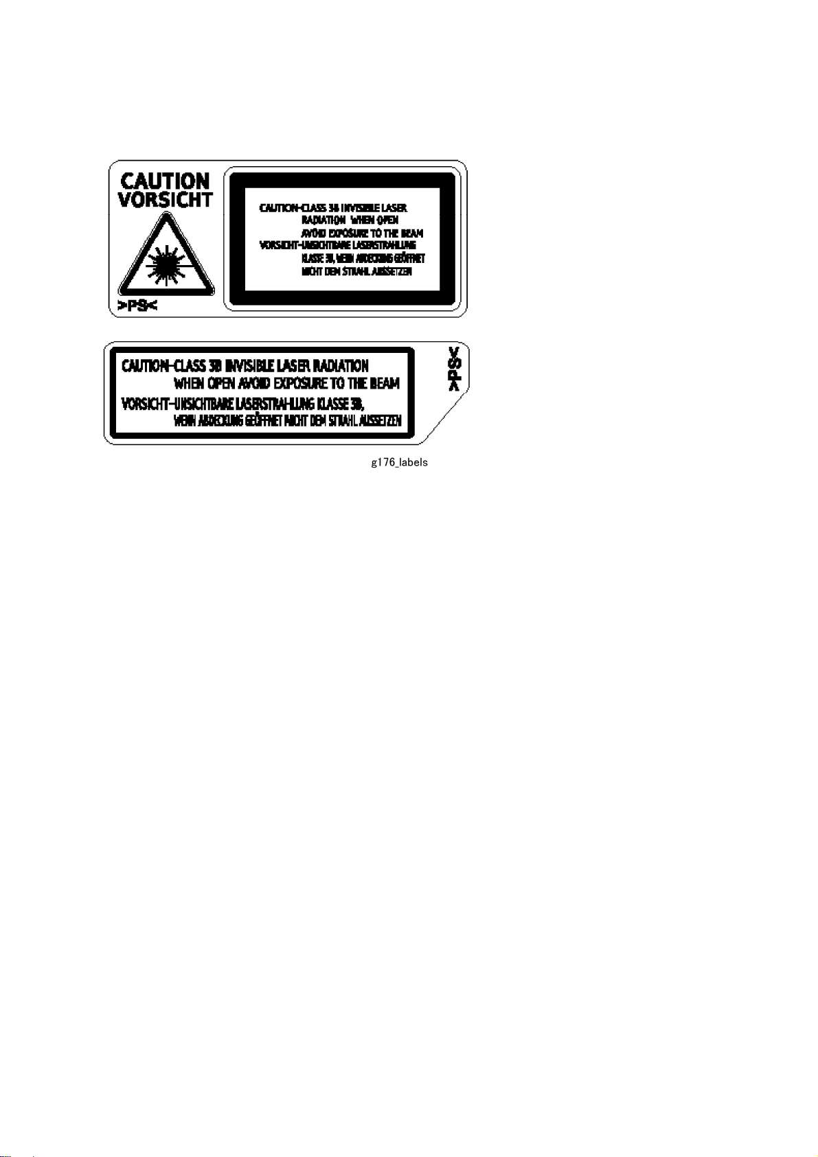
Caution Labels
Page 15

Conventions
Conventions
Symbol What it means
Refer to section number
See Core Tech Manual for details
Screw
Connector
E-ring
C-ring
The following notations are used in text to describe the direction of paper feed: lengthwise and
sideways. The annotations “SEF” and “LEF” denote “Short Edge Feed” and “Long Edge Feed”.
(The arrows indicate the direction of paper feed.)
Page 16

PRODUCT INFORMATION
REVISION HISTORY
Page Date Added/Updated/New
None
Page 17

Page 18

1. PRODUCT INFORMATION
Specifications
1.1 SPECIFICATIONS
See Appendices:
Appendices: Basic Specifications
Appendices: Controller Specifications
Product
Information
SM 1-1 M020/M021
Page 19
1.2 MACHINE CONFIGURATION
1.2.1 SYSTEM COMPONENTS
Main
Item Machine code Remarks
Mainframe (45 / 47 ppm) M020
Mainframe (50 / 52 ppm) M021
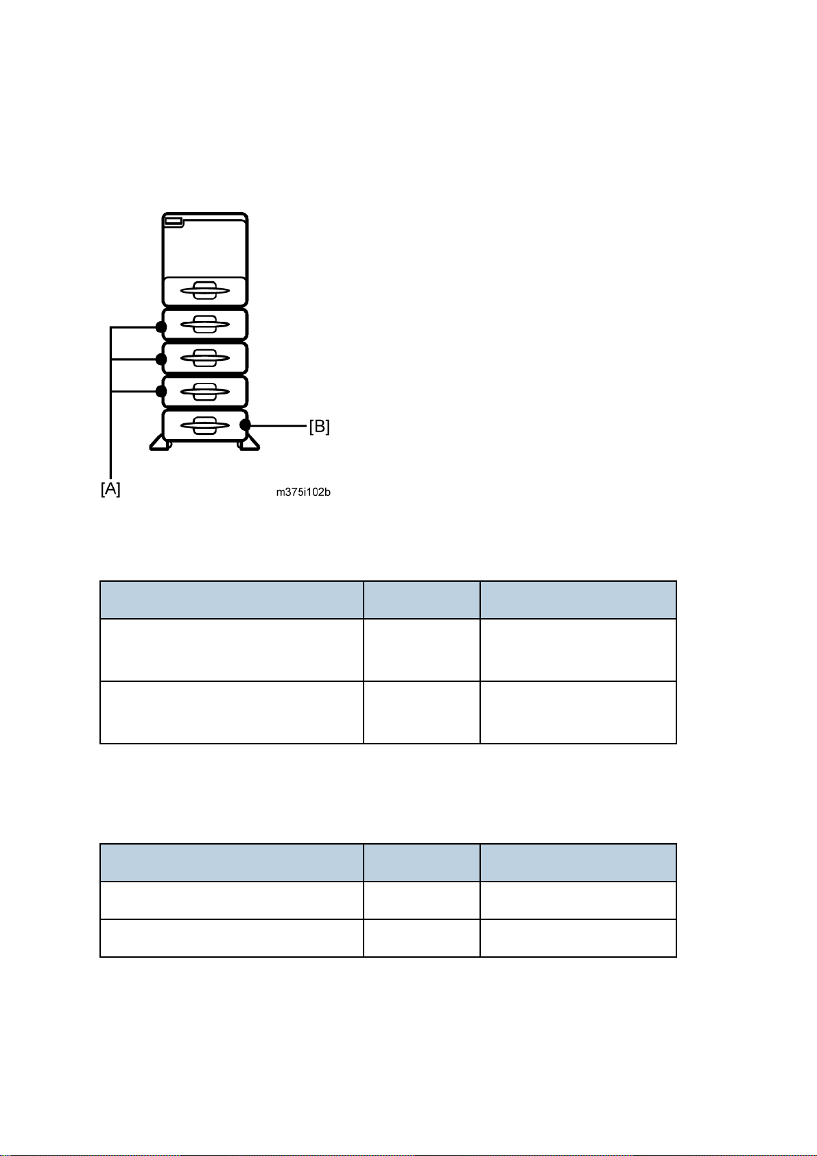
Options
Item Machine code Remarks
45 ppm (A4 - SEF)
47 ppm (LT - SEF)
50 ppm (A4 - SEF)
52 ppm (LT - SEF)
Paper Feed Unit TK1120 [A] M386 Without casters
Paper Feed Unit TK1130 [B] M389 With casters
M020/M021 1-2 SM
Page 20
Machine Configuration
Product
Information
SM 1-3 M020/M021
Page 21

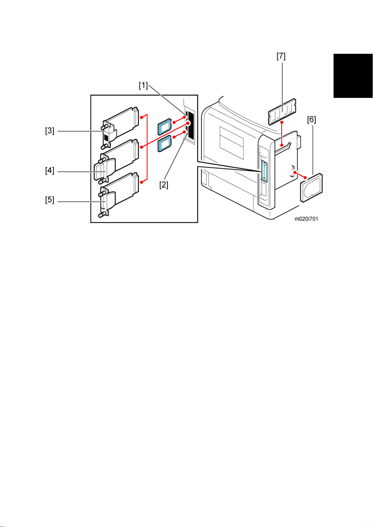
Internal options
Item Machine code Remarks
Memory Unit Type G 256 MB [7] D362 Optional for M020
Memory Unit Type I 512 MB [7] D435 Optional for M020
Hard Disk Drive Type 4310 [6] M394 Optional for M020
IEEE 1284 Interface Board Type A [5] B679
IEEE 802.11a/g interface Unit Type L
[4]
IEEE 802.11a/g Interface Unit Type M
[4]
Gigabit Ethernet Board Type A [3] G874
Gigabit Ethernet Board Type C [3] M397 For NA
SD Card for Netware Printing Type E
[1]
IPDS Unit Type 5200 [1] M388-04 For NA
IPDS Unit Type 5200 [1] M388-05 For EU
SD Card for Fonts Type C [1] M352 For EU
M344 For NA
M344 For EU
M388-03
M020/M021 1-4 SM
Page 22
1.3 OVERVIEW
Overview
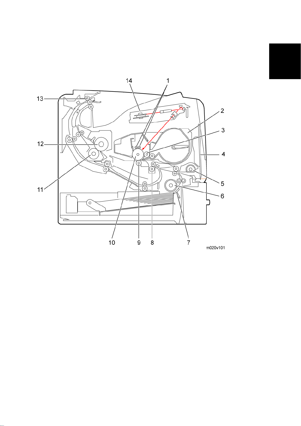
1.3.1 MECHANICAL COMPONENT LAYOUT
Product
Information
1. Charge roller 8. Registration roller
2. Cartridge (AIO-type) 9. Transfer roller
3. Development roller 10. Drum
4. By-pass feed tray 11. Pressure roller
5. By-pass feed roller 12. Hot roller
6. Paper feed roller 13. Paper exit roller
7. Friction pad 14. Laser unit
SM 1-5 M020/M021
Page 23
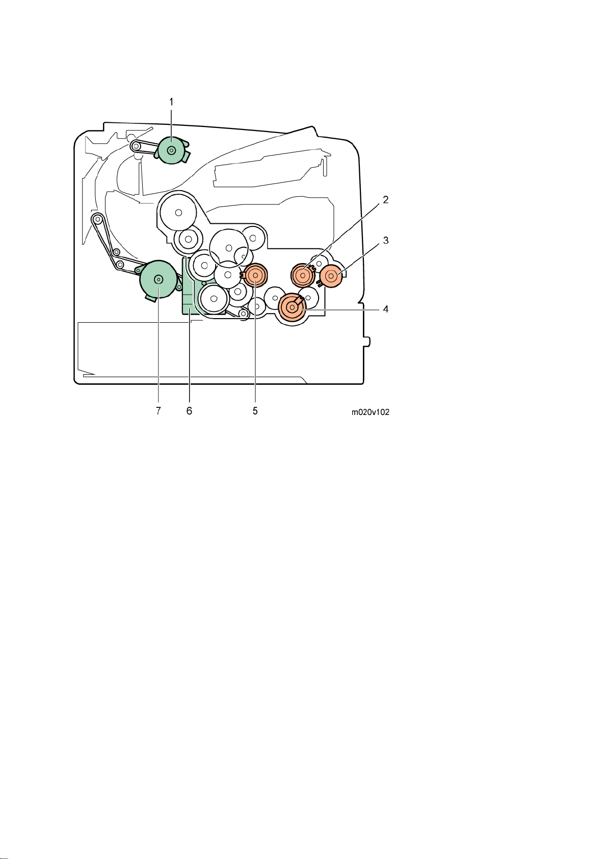
Drive Layout
1. Paper exit motor
2. Relay clutch
3. By-pass feed clutch
4. Paper feed clutch
5. Registration clutch
6. Main motor
7. Duplex motor
M020/M021 1-6 SM
Page 24

1.3.2 PAPER PATH
Overview
Product
Information
1. Paper feed through duplex unit
2. Paper exit to the paper stack
3. Paper feed from tray 1
4. Paper feed from by-pass tray
5. Paper feed from optional PFU (tray 2)
6. Paper feed from optional PFU (tray 3)
7. Paper feed from optional PFU (tray 4)
8. Paper feed from optional PFU (tray 5)
SM 1-7 M020/M021
Page 25

Page 26

INSTALLATION
REVISION HISTORY
Page Date Added/Updated/New
None
Page 27

Page 28

2. INSTALLATION
2.1 MACHINE INSTALLATION
Refer to the following sections for installation details for all models.
Category Item Machine code References
Machine Installation
Main unit -
Paper Feed Unit TK1120 M386 p.2-22
Paper Feed Unit TK1130 M389 p.2-27
Memory Unit Type G 256 MB D362
Memory Unit Type I 512 MB D435
Hard Disk Drive Type 4310 M394
IEEE 802.11a/g interface Unit
Type L (NA) *1
IEEE 802.11a/g interface Unit
Options
Type M (EU) *1
IEEE 1284 Interface Board
Type A
M020/
M021
M344
M344
B679
Quick Installation Guide
p.2-4, p.2-5
Installation
Gigabit Ethernet Board Type A
*1
Gigabit Ethernet Board Type C
*1
IPDS Unit Type 5200 D571
SD Card for Netware Printing
Type E
Drivers -
*1: These units cannot be installed at the same time.
SM 2-1 M020/M021
G874
M397
Software Guide,
M388-03
Section 6
Software Guide,
Section 1
Page 29
Installation Requirements
2.2 INSTALLATION REQUIREMENTS
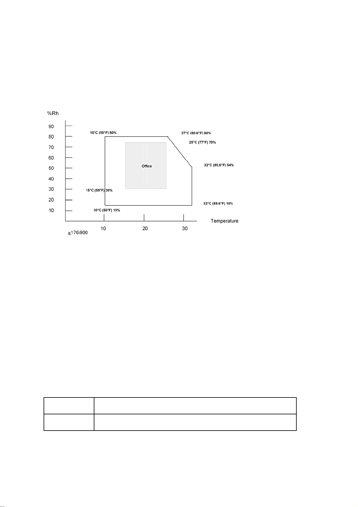
2.2.1 ENVIRONMENT
–Temperature and Humidity Chart–
Temperature Range: 10°C to 32°C (50°F to 89.6°F)
Humidity Range: 15% to 80% RH
Ambient Illumination: Less than 1,500 lux (Do not expose to direct sunlight.)
Ventilation: Room air should turn over at least 3 times/hr/person
3
Ambient Dust: Less than 0.1 mg/m
Do not install the machine where it will be exposed to direct sunlight or to direct airflow
(from a fan, air conditioner, air cleaner, etc.).
Do not install the machine where it will be exposed to corrosive gas.
Install the machine at a location lower than 2,000 m (6,560 ft.) above sea level.
Place the machine on a firm and level base.
Do not install the machine where it may be subjected to strong vibration.
2.2.2 MACHINE LEVEL
Front to back: Within 5 mm (0.2") of level
Right to left: Within 5 mm (0.2") of level
M020/M021 2-2 SM
Page 30
Installation Requirements
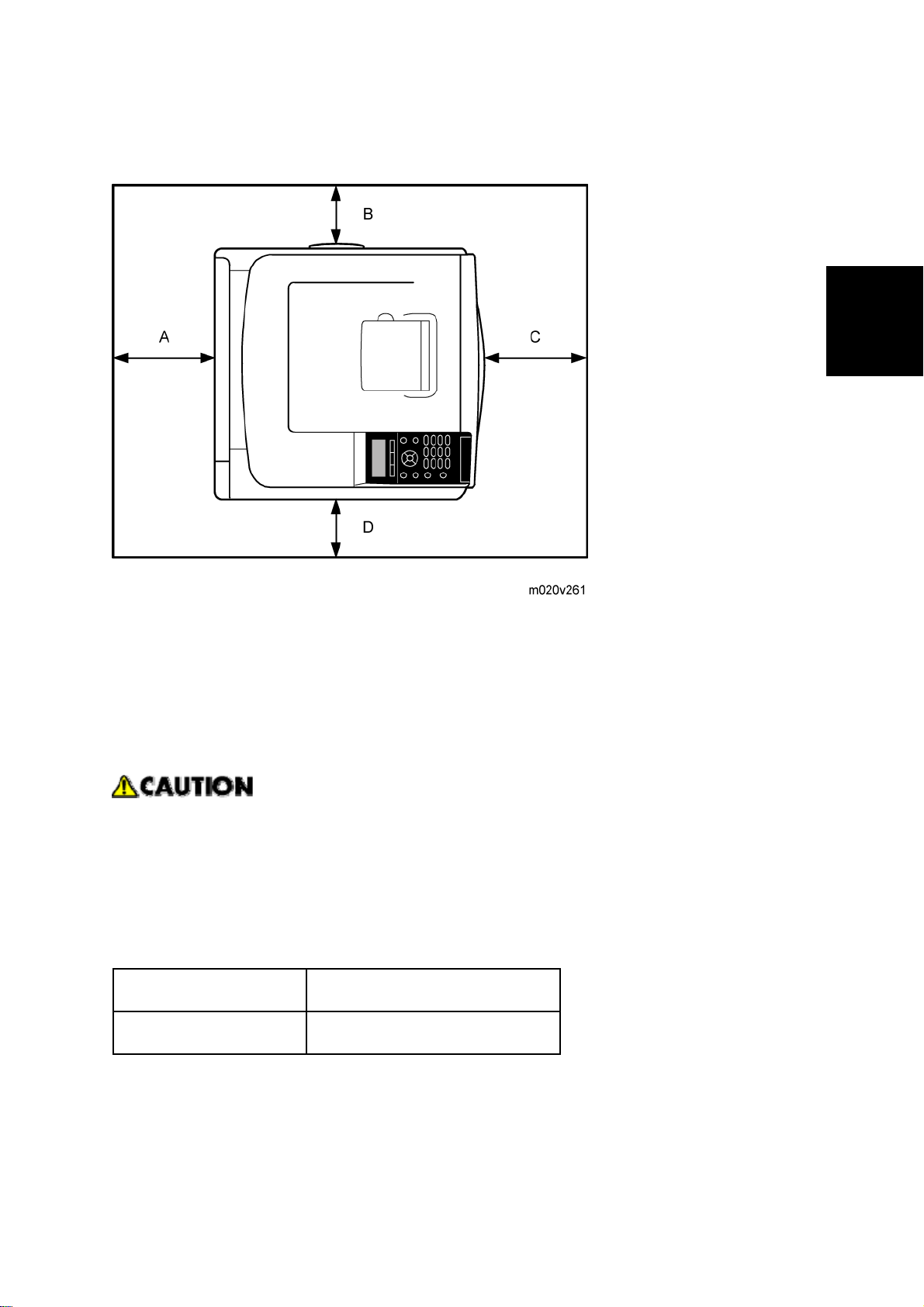
2.2.3 MINIMUM OPERATIONAL SPACE REQUIREMENTS
Place the machine near the power source, providing clearance as shown.
Installation
A: Rear – 200 mm (7.9")
B: Right – 100 mm (4.0")
C: Front – 350 mm (13.8")
D: Left – 100 mm (4.0")
2.2.4 POWER SUPPLY
Make sure that the wall outlet is near the machine and easily accessible. After
completing installation, make sure the plug fits firmly into the outlet.
Avoid multiple connections to the same power outlet.
Be sure to ground the machine.
Input voltage:
North America: 120 – 127 V, 60 Hz, 12 A
Europe/Asia: 220 – 240 V, 50/60 Hz, 8 A
Image quality guaranteed at rated voltage ± 10%.
Operation guaranteed at rated voltage ± 15%.
SM 2-3 M020/M021
Page 31

Controller Options
2.3 CONTROLLER OPTIONS
2.3.1 OVERVIEW
This machine has an I/F card slot for optional I/F connections and SD card slots.
After you install an option, check that the machine can recognize it (see "Check All
Connections" at the end of this section).
I/F Card Slots
The I/F slot is used for one of the optional I/F connections (only one can be installed):
Gigabit Ethernet [3], IEEE802.11a/g (Wireless LAN) [4] or IEEE 1284 interface board [5].
SD Card Slots
Slot 1 [1] (Upper) is used for the Security Card (standard) and IPDS Unit.
If IPDS Unit is to be installed, first merge IPDS application into the Security Card with SP
mode
Slot 2 [2] (Lower) is used for the VM card and service (for example, updating the firmware).
SDRAM slot
The SDRAM slot is used for the SDRAM memory [7] (Standard for type M021, optional for
type M020).
Hard disk connector
Hard disk connector is used for the hard disk [6] (Standard for type M021, optional for type
M020) installation.
M020/M021 2-4 SM
Page 32

Controller Options
2.3.2 INSTALLING THE SD MEMORY CARD OPTIONS
Installation
Keep SD memory cards out of reach of children. If a child swallows an SD memory
card, consult a doctor immediately.
Do not subject the card to physical shocks.
The VM card is optional for M020 models only. To use it, the optional 512 MB SDRAM
module must be installed.
1. Check the contents of the package.
2. Turn off the power, and then unplug the power cord.
Installation
3. Remove the screw, and then carefully remove the cover of the SD card slot.
4. Carefully push in the SD card (notched corner downward and leading), until it clicks into
place.
Insert the SD card in the appropriate slot as follows:
Upper slot: SD font card, NetWare card, Security SD card (Standard for M020), IPDS
card.
Lower slot: For service only (Firmware update, application move, etc.)
The SD card supplied with the optional hard disk (M020 model only) can be used in either
of the two slots.
SM 2-5 M020/M021
Page 33

Controller Options
5. Reattach the cover over the SD card. Fasten the screw to secure the cover.
Do not touch the card while the printer is in use. It may come loose, even if pushed only
slightly. The slot cover must be reattached.
You can confirm that the SD card was installed correctly by checking the control panel
menu. Depending on the SD card, certain menu items appear on the display.
SD card supplied with the optional hard disk (M020 model only): Make sure [Machine
Data Encryption] appears in [Security Options]. Depending on settings, [Machine Data
Encryption] might not appear. For details about how to confirm this setting, consult your
administrator.
NetWare card: Make sure [NetWare] appears in [Effective Protocol] under [Network].
M020/M021 2-6 SM
Page 34

Controller Options
2.3.3 SD CARD APPLICATION MOVE
The PostScript3 application and fonts cannot be moved to another SD card. However,
other applications can be moved onto the PostScript3 SD card.
Overview
The service program "SD Card Appli Move" (SP5-873) lets you copy application programs from
one SD card to another SD card.
Slot 1 (Upper) is used to store application programs. But there are 3 possible applications
(PostScript 3, DOS (DataOverwriteSecurity) unit, PictBridge). You cannot run application
programs from Slot 2 (Lower). However you can move application programs from Slot 2 (Lower)
to Slot 1 (Upper) with the following procedure.
Make sure that the target SD card has enough space.
1. Enter SP5873 "SD Card Appli Move".
2. Then move the application from the SD Card in Slot 2 (Lower) to the SD Card in Slot 1
(Upper).
Do steps 1 - 2 again if you want to move another application program.
3. Exit the SP mode.
Be very careful when you do the SD Card Appli Move procedure:
The data necessary for authentication is transferred with the application program from an
SD card to another SD card. Authentication fails if you try to use the SD card af ter you copy
the application program from one card to another card.
Do not use the SD card if it has been used before for other purposes. Normal operation is
Installation
not guaranteed when such an SD card is used.
Keep the SD card in a safe place after you copy the application program from one card to
another card. This is done for the following reasons:
1) The SD card can be the only proof that the user is licensed to use the application
program.
2) You may need to check the SD card and its data to solve a problem in the future.
SM 2-7 M020/M021
Page 35

Controller Options
Move Exec
The menu "Move Exec" (SP5873-001) lets you copy application programs from the original SD
card to another SD card.
Do not set ON (Lock) the write-protect switch of the system SD card or application SD
card on the machine. If the write-protect switch is ON, a download error (e.g. Error
Code 44) occurs during a firmware upgrade or application merge.
1. Turn the main switch off.
2. Make sure that an SD card is in SD Card Slot 1 (Upper). The application program is copied
to this SD card.
3. Insert the SD card with the application program in SD Card Slot 2 (Lower).The application
program is copied from this SD card.
4. Turn the main switch on.
5. Start the SP mode.
6. Select SP5873-001 "Move Exec."
7. Follow the messages shown on the operation panel.
8. Turn the main switch off.
9. Remove the SD card from SD Card Slot 2 (Lower).
10. Turn the main switch on.
11. Check that the application programs run normally.
Undo Exec
"Undo Exec" (SP5873-002) lets you copy back application programs from an SD card to the
original SD card. You can use this program when, for example, you have mistakenly copied
some programs by using Move Exec (SP5873-001).
Do not set ON (Lock) the write protect switch of the system SD card or application SD
card on the machine. If the write protect switch is ON, a download error (e.g. Error
Code 44) occurs during a firmware upgrade or application merge.
1. Turn the main switch off.
2. Insert the original SD card in SD Card Slot 2 (Lower). The application program is copied
back into this card.
3. Insert the SD card with the application program in SD Card Slot 1 (Upper).The application
program is copied back from this SD card.
4. Turn the main switch on.
5. Start the SP mode.
6. Select SP5873-002 "Undo Exec."
M020/M021 2-8 SM
Page 36

7. Follow the messages shown on the operation panel.
8. Turn the main switch off.
9. Remove the SD card from SD Card Slot 2 (Lower).
This step assumes that the application programs in the SD card are used by the
machine.
10. Turn the main switch on.
11. Check that the application programs run normally.
Controller Options
12. Make sure that the machine can recognize the option (see "p.2-21" at the end of this
section).
2.3.4 IEEE 802.11 A/G (WIRELESS LAN)
Installation Procedure
Unplug the main machine power cord before you do the following procedure.
You can only install one of the network interfaces or printer enhanced option at one time: IEEE
802.11 a/g (Wireless LAN), Gigabit Ethernet, or File Format Converter.
Installation
1. Remove the two screws and remove the cover of the slot in which the Wireless LAN
interface board is to be installed.
2. Fully insert the Wireless LAN interface board.
SM 2-9 M020/M021
Page 37

Controller Options
3. Tighten the two screws to secure the interface board.
Check the Wireless LAN interface board is connected firmly to the interface board slot.
You may have to move the machine if the reception is not clear.
Make sure that the machine is not located near an appliance or any type of equipment
that generates strong magnetic fields.
Put the machine as close as possible to the access point.
UP Mode Settings for Wireless LAN
Enter the UP mode. Then do the procedure below to perform the initial interface settings for
IEEE 802.11 a/g. These settings take effect every time the machine is powered on.
You cannot use the wireless LAN if you use Ethernet.
1. Press the "User Tools/Counter" key.
2. On the touch panel, press "System Settings".
The Network I/F (default: Ethernet) must be set for either Ethernet or wireless LAN.
3. Select "Interface Settings".
4. Press "Wireless LAN". Only the wireless LAN options show.
5. Communication Mode. Select either "802.11 Ad hoc" or "Infrastructure".
6. SSID Setting. Enter the SSID setting. (The setting is case sensitive.)
7. Channel. You need this setting when Ad Hoc Mode is selected.
Region A (mainly Europe and Asia)
Range: 1-13, 36, 40, 44 and 48 channels (default: 11)
Region B (mainly North America)
Range: 1-11, 36, 40, 44 and 48 channels (default: 11)
M020/M021 2-10 SM
Page 38

Controller Options
The allowed range for the channel settings may vary for different countries.
In some countries, only the following channels are available: Range: 1-1 1 channels
(default: 11)
8. WEP (Encryption) Setting. The WEP (Wired Equivalent Privacy) setting is designed to
protect wireless data transmission. The same WEP key is required on the receiving side in
order to unlock encoded data. There are 64 bit and 128 bit WEP keys.
WEP:
Selects "Active" or "Inactive" ("Inactive" is default.).
Range of Allowed Settings:
64 bit: 10 characters
128 bit: 26 characters
9. Press "Return to Default" to initialize the wireless LAN settings.
Press "Yes" to initialize the following settings:
Transmission mode
Channel
Transmission Speed
WEP
SSID
WEP Key
Installation
SM 2-11 M020/M021
Page 39

Controller Options
SP Mode and UP Mode Settings for IEEE 802.11 a/g Wireless LAN
The following SP commands and UP modes can be set for IEEE 802.11 a/g.
SP No. Name Function
5840-006 Channel MAX
5840-007 Channel MIN
Transmission
5840-008
Speed
5840-011 WEP Key Select Used to select the WEP key (Default: 00).
UP mode Name Function
SSID Used to confirm the current SSID setting.
WEP Key Used to confirm the current WEP key setting.
WEP Mode
Sets the maximum range of the channel settings for the
country.
Sets the minimum range of the channel settings
allowed for the country.
Sets the transmission speed.
Auto, 54 Mbps, 48 Mbps, 36 Mbps, 24 Mbps, 18 Mbps,
12 Mbps, 9 Mbps, 6 Mbps, 11 Mbps, 5.5 Mbps, 2 Mbps,
1 Mbps (Default: Auto).
Used to show the maximum length of the string that
can be used for the WEP Key entry.
M020/M021 2-12 SM
Page 40

Controller Options
2.3.5 IEEE 1284 INTERFACE BOARD
Unplug the main machine power cord before you do the following procedure.
Before beginning work, ground yourself by touching something metal to discharge any
static electricity. Static electricity can damage the IEEE 1284 interface board.
Do not subject the IEEE 1284 interface board to physical shocks.
For connection to the IEEE 1284 interface board, use a half pitch 36-pin interface
cable.
1. Check the contents of the package.
Installation
2. Remove the two screws and remove the cover of the slot in which the 1284 interface board
is installed.
3. Fully insert the IEEE 1284 interface board.
SM 2-13 M020/M021
Page 41

Controller Options
4. Tighten the two screws to secure the interface board.
Confirm that the IEEE 1284 interface board was correctly installed by printing the
configuration page. If it is correctly installed, "Parallel Interface" will appear for "Device
Connection" on the configuration page.
If the board was not installed properly, repeat the p rocedure from step 3.
For details on printing the configuration, see "p.2-21" at the end of this section.
M020/M021 2-14 SM
Page 42

2.3.6 GIGABIT ETHERNET
Unplug the main machine power cord before you do the following procedure.
1: Gigabit Ethernet Board
2: Protective caps (one each for the Ethernet port and the USB port)
Controller Options
Installation
3: Ferrite core (Design of the ferrite core varies according to printer model.)
1. Check the contents of the package.
2. Disconnect the cables from the Ethernet port and USB port of the printer, and cover each
port with its protective cap.
3. Remove the two screws and remove the cover of the slot in which the Gigabit Ethernet
board is installed.
SM 2-15 M020/M021
Page 43

Controller Options
4. Fully insert the Gigabit Ethernet board.
5. Tighten the two screws to secure the Gigabit Ethernet board.
Check the Gigabit Ethernet board is connected firmly to the interface board slot.
6. Attach the ferrite core [3] to the LAN cable, and connect the LAN cable to the machine.
7. Make sure that the machine can recognize this option (see ‘p.2-21’ at the end of this
section).
M020/M021 2-16 SM
Page 44

Controller Options
2.3.7 MEMORY UNIT TYPE G 256MB / I 512MB (ONLY FOR M020)
Unplug the main machine power cord before you do the following procedure.
1. Controller unit (
2. Place the controller board on a flat surface. The SDRAM module is installed in the slot
shown in the illustration above.
p.4-43)
Installation
3. To install the recommended memory, align the notch of the memory module with the
protruding part of the vacant slot, and then carefully insert the module at an angle.
4. Keeping the module at an angle, press it down until it clicks into place.
SM 2-17 M020/M021
Page 45

Controller Options
5. Align the controller board with the top and bottom rails, and then push it carefully in, until it
stops.
6. Fasten the controller board to the printer with the two screws.
After finishing the installation, you can check the SDRAM module is properly installed:
Print the configuration page from the [List/Test Print] menu. If it is installed properly , the
memory capacity will appear under "Total Memory" on the configuration page.
The table below shows the total SDRAM module capacities.
Standard Extended Total
256 MB 256MB 512 MB
256 MB 512 MB 768MB
M020/M021 2-18 SM
Page 46

2.3.8 HARD DISK DRIVE TYPE 2670 (ONLY FOR M020)
Unplug the main machine power cord before you do the following procedure.
1: Hard disk
2: Screws (Knob screws x 3)
1. Check the package contains the above.
Controller Options
Installation
2. Controller unit (
3. Place the controller board on a flat surface. The hard disk is installed in the slot shown in
the illustration above.
p.4-43)
4. Insert the protrusion on the front end of the hard disk board into the notch on the back panel
of the controller board.
Be sure to set the hard disk board parallel with the controller board.
SM 2-19 M020/M021
Page 47

Controller Options
5. Fit the hard disk on the connector of the controller board carefully until it stops.
6. Tighten the two screws by turning them clockwise with a coin, and then secure the hard
disk board by tightening the third screw from the under side of the controller board.
7. Align the controller board with the top and bottom rails, and then push it carefully in, until it
stops.
8. Fasten the controller board to the printer with the two screws.
M020/M021 2-20 SM
Page 48

Controller Options
After finishing installation, you can check whether the hard disk is properly installed:
Print the configuration page from the [List/Test Print] menu. If it is installed properly , you
will see "Hard Disk" will appear for "Device Connection" on the configuration page.
If the Hard disk is not properly installed, repeat this procedure.
For details on printing the configuration, see "p.2-21" at the end of this section.
2.3.9 CHECK ALL CONNECTIONS
1. Plug in the power cord. Then turn on the main switch.
2. Enter the printer user mode. Then print the configuration page.
User Tools > Printer Settings > List Test Print > Config. Page
All installed options are shown in the "System Reference" column.
2.3.10 IC CARD READER (EXTERNAL OPTIONS) ATTACHING
LOCATION
Installation
To enable good communication between the IC card reader and the IC card, install the IC card
reader at the position above [A].
Position the IC card reader with the upper edge 10 mm (0.4 in.) below the air inlet [B].
Align the front edge of the IC card reader with the front line of the air inlet [C].
The USB cable of the IC card reader should be fixed with clamps to prevent it from
sagging.
SM 2-21 M020/M021
Page 49

Paper Feed Unit TK1120 (M386)
2.4 PAPER FEED UNIT TK1120 (M386)
2.4.1 ACCESSORY CHECK
Confirm that you have these accessories.
Description Q'ty
Installation instructions 1
EMC sheet 1
Fixation screws 2
2.4.2 INSTALLATION PROCEDURE
Unplug the main machine's power cord before starting the following procedure.
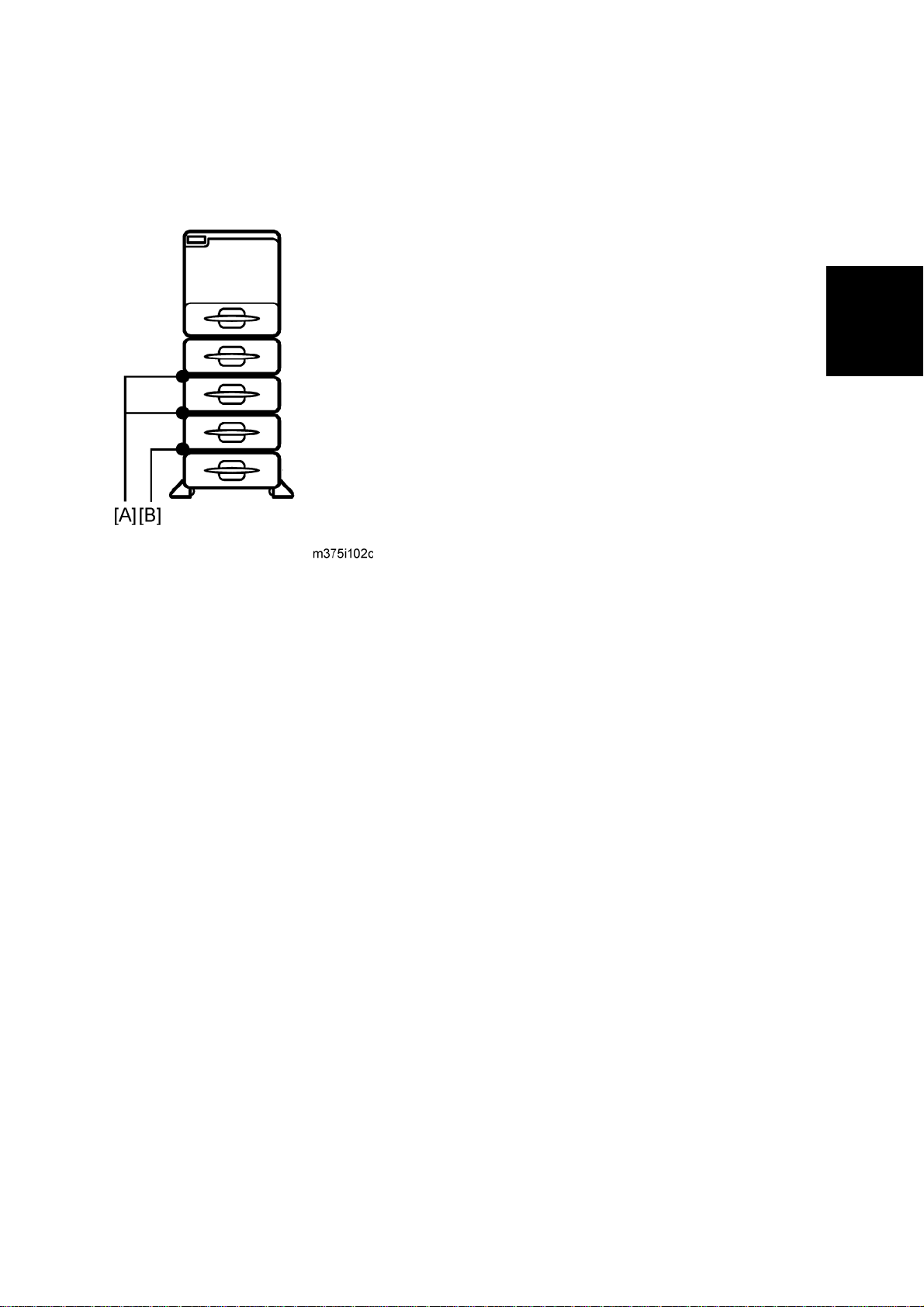
The number of optional paper feed units that can be attached depends on the location where
the machine is installed.
[A]: Up to three paper feed units (M386 [D]) can be installed on a desk.
[B]: Up to three paper feed units (M386 [D]) and one paper feed unit (M389 [E]) can be
installed on the floor.
[C]: Attach the optional paper feed unit with casters (M389 [E]) to the bottom of the machine
to install the machine directly on the floor.
M020/M021 2-22 SM
Page 50

Paper Feed Unit TK1120 (M386)
1. Remove all tape and cardboard from the optional paper feed unit [A].
2. Pull the paper tray of the main unit part way out; then, remove the tape and cardboard in
the paper tray, and push the tray back in.
Installation
3. Lift the printer using the inset grips on both sides of the printer.
When moving the printer, do not hold on the following parts as doing so could
cause a malfunction:
The handle of the standard paper tray.
The underside of the by-pass tray.
SM 2-23 M020/M021
Page 51

Paper Feed Unit TK1120 (M386)
4. Set the machine [A] on the paper feed unit [B].
Two people are required to lift the machine.
When installing a second paper feed unit, place it on the first paper feed unit
before placing the printer onto the pair of paper feed units
5. Remove the paper(s) tray from the paper tray unit(s).
6. Load paper into the paper tray(s). Adjust the side and end fences as necessary. If loading
1
/2"x 14" paper, remove the end fence and set it in the special compartment.
8
7. Insert the paper tray(s) back in the paper tray unit(s).
M020/M021 2-24 SM
Page 52
Paper Feed Unit TK1120 (M386)
2.4.3 WHEN STACKING FOUR OPTIONAL PAPER FEED UNITS
Paper feed units should be fixed to each other with screws when stacking four optional paper
feed units. Fix the paper feed units to each other as described below.
Installation
1. Between top three optional units [A]
2. Between the unit with casters (forth optional) and the third optional unit [B]
SM 2-25 M020/M021
Page 53

Paper Feed Unit TK1120 (M386)
Fixing the units together
1. Pull out the paper trays of the paper feed units to be fixed.
2. Fix the paper feed unit at the rear side [A] with the two screws that come with the paper
feed unit.
Never detach the stabilizers of the paper feed unit with casters (M389).
M020/M021 2-26 SM
Page 54

2.5 PAPER FEED UNIT TK1130 (M389)
2.5.1 ACCESSORY CHECK
Confirm that you have these accessories.
Description Q'ty
Paper Feed Unit TK1130 (M389)
Installation instructions 1
EMC sheet 1
2.5.2 INSTALLATION PROCEDURE
Unplug the main machine's power cord before starting the following procedure.
Installation
The number of optional paper feed units that can be attached depends on the location where
the machine is installed.
[A]: Up to three paper feed units (M386 [D]) can be installed on a desk.
[B]: Up to three paper feed units (M386 [D]) and one paper feed unit (M389
[E]) can be installed on the floor.
[C]: Attach the optional paper feed unit with casters (M389 [E]) to the bottom of the machine
to install the machine directly on the floor.
SM 2-27 M020/M021
Page 55

Paper Feed Unit TK1130 (M389)
1. Remove all tape and cardboard from the optional paper feed unit [A].
2. Pull the paper tray of the main unit part way out; then, remove the tape and cardboard in
the paper tray, and push the tray back in.
3. Lift the printer using the inset grips on both sides of the printer.
When moving the printer, do not hold on the following parts as doing so could
cause a malfunction:
The handle of the standard paper tray.
The underside of the by-pass tray.
M020/M021 2-28 SM
Page 56

4. Set the machine [A] on the paper feed unit [B].
Paper Feed Unit TK1130 (M389)
Installation
Two people are required to lift the machine.
When installing a second paper feed unit, place it on the first paper feed unit
before placing the printer onto the pair of paper feed units
5. Remove the paper(s) tray from the paper tray unit(s).
6. Load paper in the paper tray(s). Adjust the side and end fences as necessary. If loading
1
/2"x 14" paper, remove the end fence and set it in the special compartment.
8
7. Insert the paper tray(s) back in the paper tray unit(s).
SM 2-29 M020/M021
Page 57

Paper Feed Unit TK1130 (M389)
2.5.3 WHEN STACKING FOUR OPTIONAL PAPER FEED UNITS
Paper feed units should be fixed each other with screws when stacking four optional paper feed
units. Fix the paper feed units to each other as described below.
1. Between top three optional units [A]
2. Between the unit with casters (forth optional) and third optional unit [B].
M020/M021 2-30 SM
Page 58

Fixing the units together
1. Pull out the paper trays of the paper feed units to be fixed.
Paper Feed Unit TK1130 (M389)
Installation
2. Fix the paper feed unit at the rear side [A] with the two screws that come with the paper
feed unit.
Never detach the stabilizers of the paper feed unit with casters (M389).
SM 2-31 M020/M021
Page 59

Page 60

PREVENTIVE MAINTENANCE
REVISION HISTORY
Page Date Added/Updated/New
None
Page 61

Page 62

Maintenance Tables
3. PREVENTIVE MAINTENANCE
3.1 MAINTENANCE TABLES
3.1.1 USER MAINTENANCE
The customer can replace all PM items with the Maintenance Kit.
The user can maintain this machine. For more see "Printer Engine Service Mode".
The operation panel shows “Replace Maintenance Kit” when the PM counter reaches 120 k.
After the user replaces the fusing unit in the maintenance kit, the machine automatically resets
the PM counter.
Item Quantity Remarks
Fusing unit 1 -
Transfer roller 1 -
Paper feed roller 5 For standard and optional tray(s)
Friction pad 5 For standard and optional tray(s)
3.1.2 SERVICE MAINTENANCE
See "Appendices" for the following information:
Preventive Maintenance Items
Other Yield Parts
Preventive
Maintenance
SM 3-1 M020/M021
Page 63

PM Parts Settings
3.2 PM PARTS SETTINGS
3.2.1 BEFORE REMOVING THE OLD PM PARTS
1. Enter the SP mode.
2. Output the SMC logging data with SP5-990-004.
3. Clear the PM counters with SP7-804.
4. Exit the SP mode.
Item SP
All Units 7-804-002
Fusing Unit 7-804-003
Transfer Roller 7-804-004
Paper Feed Roller 7-804-005
For the fusing unit, there is a new unit detection mechanism. It is not necessary to reset the PM
counter.
3.2.2 AFTER INSTALLING THE NEW PM PARTS
1. Turn on the main power switch.
2. Output the SMC logging data with SP5-990-004 and check the counter values.
3. Make sure that the PM counters for the replaced units are “0” with SP7-803. If the PM
counter for a unit was not reset, then reset that counter with SP 7-804.
3.2.3 OPERATION CHECK
Check if the sample image has been printed normally.
M020/M021 3-2 SM
Page 64

REPLACEMENT AND ADJUSTMENT
REVISION HISTORY
Page Date Added/Updated/New
None
Page 65

Page 66

General Precautions
4. REPLACEMENT AND ADJUSTMENT
4.1 GENERAL PRECAUTIONS
4.1.1 PRECAUTIONS ON DISASSEMBLY
Always turn off the main power switch and unplug the machine before attempting any
of the procedures in this section.
Use extreme caution when removing and replacing components. The cables in the machine are
located very close to moving parts; proper routing is a must.
After components have been removed, any cables that have been displaced during the
procedure must be restored as close as possible to their original positions. Before removing any
component from the machine, note any cable routings that may be affected.
Before servicing the machine:
1. Verify that documents are not stored in memory.
2. Remove the print cartridge before you remove parts.
3. Unplug the power cord.
4. Work on a flat and clean surface.
5. Replace with authorized components only.
6. Do not force plastic material components.
Make sure all components are returned to their original positions.
Laser Unit
1. Do not loosen or adjust the screws securing the LD drive board on the LD unit. Doing so will
throw the LD unit out of adjustment.
2. Do not adjust the variable resistors on the LD unit, as these are permanently adjusted at
the factory. If replacement of the LD drive board is necessary, replace the entire LD unit.
3. Keep the polygon mirror and toroidal lens free of dust. Laser performance is very sensitive
to dust on these components.
4. Do not touch the shield glass or the surface of the polygon mirror with bare hands.
5. Do not adjust the Laser Synchronization detector on the LD unit, as these are permanently
Replacement
and
Adjustment
adjusted at the factory.
Transfer Roller
1. Never touch the surface of the transfer roller with bare hands.
2. Be careful not to scratch the transfer roller, as the surface is easily damaged.
SM 4-1 M020/M021
Page 67

General Precautions
Fusing
1. After installing the fusing thermistor, make sure that it is in contact with the hot roller and
that the roller can rotate freely.
2. Be careful to avoid damage to the hot roller stripper pawls and their tension springs.
3. Do not touch the fusing lamp and rollers with bare hands.
4. Make sure that the fusing lamp is positioned correctly and that it does not touch the inner
surface of the hot roller.
Paper Feed
1. Do not touch the surface of paper feed rollers.
2. To avoid misfeeds, the side and end fences in each paper tray must be positioned correctly
so as to align with loaded paper size.
4.1.2 RELEASING PLASTIC LATCHES
Many of the parts are held in place with plastic latches. The latches break easily, so release
them carefully. To release a latch, press the hook end of the latch away from the part to which it
is latched.
4.1.3 AFTER SERVICING THE MACHINE
1. Make sure all parts that require grounding are properly grounded.
2. Make sure the interlock switch is functioning.
3. Do not leave unused solder or parts inside the machine.
4. Do not leave any tools inside the machine.
5. Make sure all wires are properly connected and routed.
6. Make sure wires are not jammed between parts of the machine.
M020/M021 4-2 SM
Page 68

4.2 COVERS
4.2.1 RIGHT COVER
1. Pull the standard tray [A] out.
Covers
2. Gently push the front cover release button [B], and open the front cover [C].
3. Open the rear cover [D].
and
Adjustment
Replacement
SM 4-3 M020/M021
Page 69

Covers
4. Right cover [C] ( x 3 [A], hook [B] x 1)
To remove the right cover safely, release it from the power switch by pulling the cover
forward and outward slightly, and then release it from the Inlet socket by pushing the
cover backward slightly.
M020/M021 4-4 SM
Page 70

4.2.2 LEFT COVER
1. Pull the standard paper tray out ( p.4-3).
Covers
2. Open the front cover (
3. Slide the control board unit [B] out (Knob screw [A] x 2).
4. Open the rear cover (
p.4-3).
p.4-3).
and
Adjustment
Replacement
5. Left cover [A] (
SM 4-5 M020/M021
[B] x 4, hooks [C] x 2).
Page 71

Covers
4.2.3 UPPER COVER
1. Right cover ( p.4-3)
2. Left cover (
3. Open the front cover and the rear cover.
4. 4 screws [A].
5. Operation panel (
p.4-5)
p.4-10)
6. Part [A] of upper cover.
7. Part [B] of upper cover (Hooks [C] x 2).
M020/M021 4-6 SM
Page 72

4.2.4 FRONT COVER
1. Pull out the standard paper tray.
Covers
2. By-pass tray (
3. Open the front cover [B].
4. Right cover (
5. Left cover (
p.4-32)
p.4-3)
p.4-5)
Replacement
and
Adjustment
6. Close the front cover [B].
7. Release the tension spring [A].
8. Reopen the front cover [B].
SM 4-7 M020/M021
Page 73

Covers
9. Front cover [A] (Hooks x 2).
Remove the by-pass tray unit before removing the front cover.
Close the front cover before releasing the tension spring.
M020/M021 4-8 SM
Page 74

4.2.5 REAR COVER
1. Open the rear cover.
Covers
2. Rear cover [A](Hooks x 2).
To remove the rear cover easily, release the right hook by pushing the cover against
the left side of mainframe lightly, and then pull out the right corner.
and
Adjustment
Replacement
SM 4-9 M020/M021
Page 75

Covers
4.2.6 OPERATION PANEL
1. Left cover ( p.4-5)
2. Open the front cover.
3. Operation panel [A] ( [B] x 1, hooks x 2).
M020/M021 4-10 SM
Page 76

4.3 LASER UNIT
Turn off the main power switch and unplug the machine before attempting any of the
procedures in this section. Laser beams can seriously damage your eyes.
4.3.1 CAUTION DECAL LOCATIONS
Laser Unit
and
Adjustment
Replacement
SM 4-11 M020/M021
Page 77

Laser Unit
4.3.2 LASER UNIT
Turn off the main switch and unplug the machine before attempting any of the
procedures in this section. Laser beams can seriously damage your eyes.
1. Right cover (
2. Left cover (
3. Upper cover (
4. Grounding wire [A] and 2 connectors [B], [C] ( x 2, grounding screw x 1).
p.4-3)
p.4-5)
p.4-6)
5. Laser unit [A] (
Never touch the surface of the mirror with bare hands.
M020/M021 4-12 SM
x 4).
Page 78

When reinstalling the laser unit.
Use the scanner positioning pins (P/N: A0069104) to reinstall the unit.
Laser Unit
Set the positioning pins as shown above. Then secure the laser unit.
Replacement
and
Adjustment
SM 4-13 M020/M021
Page 79

Laser Unit
4.3.3 POLYGON MIRROR MOTOR
Turn off the main switch and unplug the machine before attempting any of the
procedures in this section. Laser beams can seriously damage your eyes.
1. Upper cover (
2. Laser unit (
3. Polygon mirror cover [A] (Grounding screw x 1, x 1, x 2, tape x 1)
Keep the tape [B] above. The tape is necessary when reassembling the laser unit.
p.4-6)
p.4-12)
4. Polygon mirror motor [A] (
M020/M021 4-14 SM
x 4, x 1)
Page 80

4.3.4 LASER SYNCHRONIZATION DETECTOR
1. Laser unit ( p.4-12)
2. Laser synchronization detector [A] (
x 1)
Laser Unit
Replacement
and
Adjustment
SM 4-15 M020/M021
Page 81

Transfer Roller
4.4 TRANSFER ROLLER
1. Open the front cover.
2. Remove the AIO unit.
3. Remove the transfer roller [A] as shown above.
Do not touch the transfer roller surface.
Set the transfer roller with its green end (indicated by the arrow in the upper-right
photo) on the right side.
Make sure that the transfer roller is set securely.
M020/M021 4-16 SM
Page 82

4.5 FUSING
4.5.1 FUSING UNIT
Before handling the fusing unit, make sure that the unit is cool enough. The fusing unit
can be very hot.
Fusing
1. Open the rear cover [A].
2. Release the lock levers [B].
3. Pull the fusing unit [C] out.
and
Adjustment
Replacement
SM 4-17 M020/M021
Page 83

Fusing
4.5.2 HOT ROLLER AND PRESSURE ROLLER SECTIONS
1. Fusing unit ( p.4-17)
2. Fusing left cover [A] (
3. Fusing right cover [B] (
4. Separate the fusing unit [A] into the hot roller section [B] and the pressure roller section [C]
(
x 4).
x 1)
x 1)
M020/M021 4-18 SM
Page 84

4.5.3 FUSING LAMP
1. Fusing unit ( p.4-17)
Fusing
2. Fusing left and right covers (
3. Lamp left stay [A] (
4. Remove the screw [B] on the left terminal of the fusing unit.
5. Lamp right stay [C] (
6. Remove the screw [D] on the right terminal of the fusing unit.
x 1)
x 1)
p.4-18)
and
Adjustment
Replacement
7. Fusing lamp [A]
SM 4-19 M020/M021
Page 85

Fusing
4.5.4 HOT ROLLER
Do not touch the fusing lamp and rollers with your bare hands.
1. Hot roller section (
2. Fusing lamp (
3. Hot roller gear [A] ( x 1)
4. Hot roller left stay [B] (
5. Hot roller right stay [C] (
6. Remove the c-ring [D].
p.4-18)
p.4-19)
x 1)
x 1)
7. Hot roller [A] (bearing x 2, insulator x 2)
Slowly pull out the hot roller from the hot roller section, making sure not to damage the
hot roller on the stripper pawls.
M020/M021 4-20 SM
Page 86

4.5.5 FUSING THERMISTOR
1. Fusing unit ( p.4-17)
2. Fusing drawer connector [A] (
x 1)
Fusing
3. Fusing thermistor [B] (
x 1, x 1)
4.5.6 THERMOSTATS
1. Hot roller ( p.4-20)
2. Thermostats [A] (
Do not reuse thermostats that are already opened. Safety is not guaranteed if you do
x 2)
Replacement
and
Adjustment
this.
SM 4-21 M020/M021
Page 87

Fusing
4.5.7 PRESSURE ROLLER
1. Pressure roller section ( p.4-18)
2. Fusing entrance guide [A] (
x 3)
3. Pressure roller [A] (bearing x 2)
M020/M021 4-22 SM
Page 88

4.5.8 FUSING CLEANING ROLLER
1. Pressure roller section ( p.4-18)
Fusing
2. Pressure roller (
3. Fusing cleaning roller [A]
p.4-22)
and
Adjustment
Replacement
SM 4-23 M020/M021
Page 89

Paper Feed
4.6 PAPER FEED
4.6.1 PAPER FEED ROLLER
1. Pull out the paper tray before removing the paper feed roller.
2. Press the paper feed roller [A] to the left side and remove it.
4.6.2 FRICTION PAD
1. Remove the paper tray from the machine before removing the friction pad.
2. Friction pad [A] (Hooks x 2, spring x 1).
M020/M021 4-24 SM
Page 90

When reinstalling the friction pad follow this order:
1. Place the spring [A].
Paper Feed
and
Adjustment
Replacement
SM 4-25 M020/M021
Page 91
Paper Feed
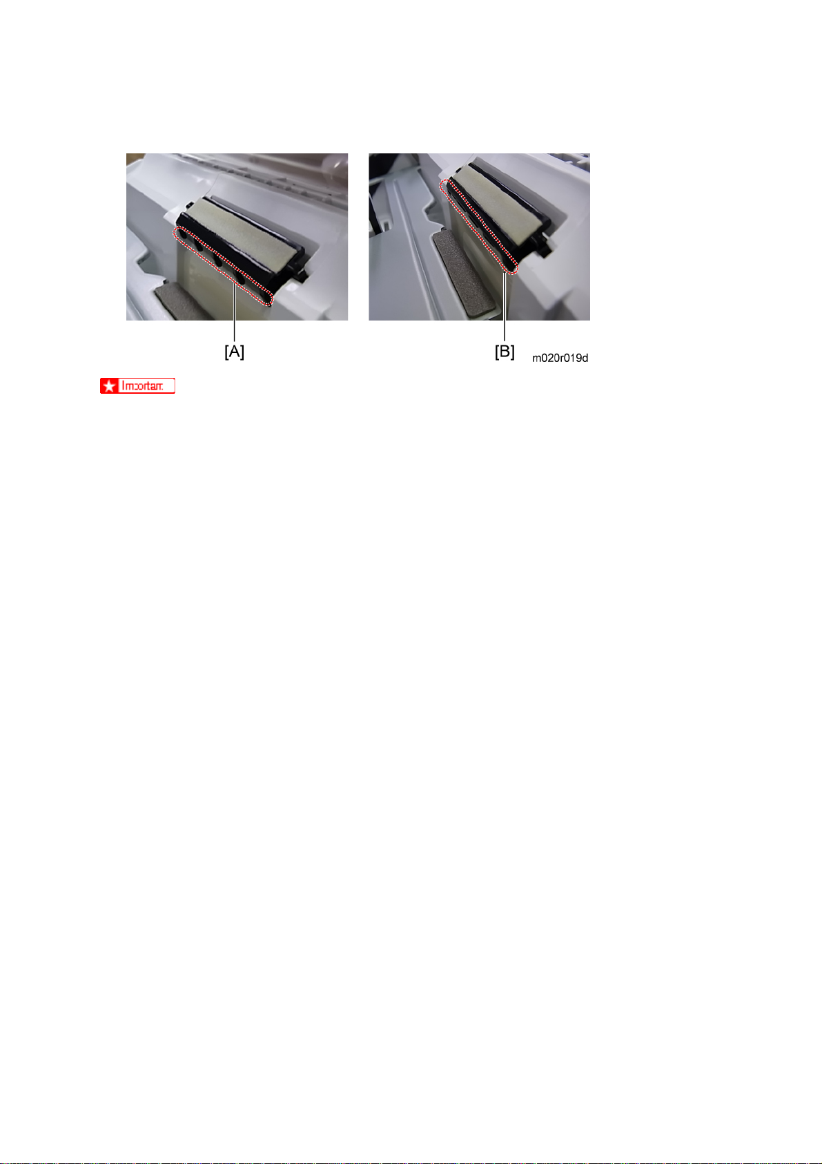
2. Gently push the friction pad [A] down into the slot while bending the Mylar sheet [B] slightly
outward.
A: No Good -- The friction pad catches the Mylar sheet.
B: Good -- Mylar sheet located at outside of the friction pad.
To prevent the friction pad from catching on the Mylar sheet, place the friction pad while
bending the Mylar sheet slightly outward.
M020/M021 4-26 SM
Page 92

4.6.3 PAPER END SENSOR
1. All optional paper tray units.
2. Pull the standard paper tray out.
3. AIO unit.
Paper Feed
4. Fusing unit (
5. Transfer roller (
6. Lay down the machine face up.
p.4-17)
p.4-16)
and
Adjustment
Replacement
7. Feeler cover [A] (
Confirm that all paper trays are detached from the machine before lying it down.
Take care when handling this machine because of its weight. (Approximately 23
kg/51 lb)
8. Remove the feeler [A] by bending the bushing slightly in the direction indicated by the arrow
in the left photo.
x 1).
SM 4-27 M020/M021
Page 93

Paper Feed
9. Paper end sensor [A] (Hooks x 3,
x 1) .
M020/M021 4-28 SM
Page 94

4.6.4 REMAINING PAPER SENSORS 1 AND 2
1. All optional paper tray units
2. Pull the standard paper tray out.
3. AIO unit.
Paper Feed
4. Fusing unit (
5. Transfer roller (
6. Lay down the machine face up.
p.4-17)
p.4-16)
and
Adjustment
Replacement
7. Feeler cover [A] (
Confirm that all paper trays are detached from the machine before lying it down.
Take care when handling this machine because of its weight. (Approximately 23
kg/51 lb)
8. Remove the feeler [A] by bending the bushing slightly in the direction indicated by the arrow
in the left photo.
x 1).
SM 4-29 M020/M021
Page 95

Paper Feed
9. Remaining paper sensor 1 [A] and remaining paper sensor 2 [B] (Hooks x 3 (For each
sensor), x 1 (For each sensor)).
M020/M021 4-30 SM
Page 96
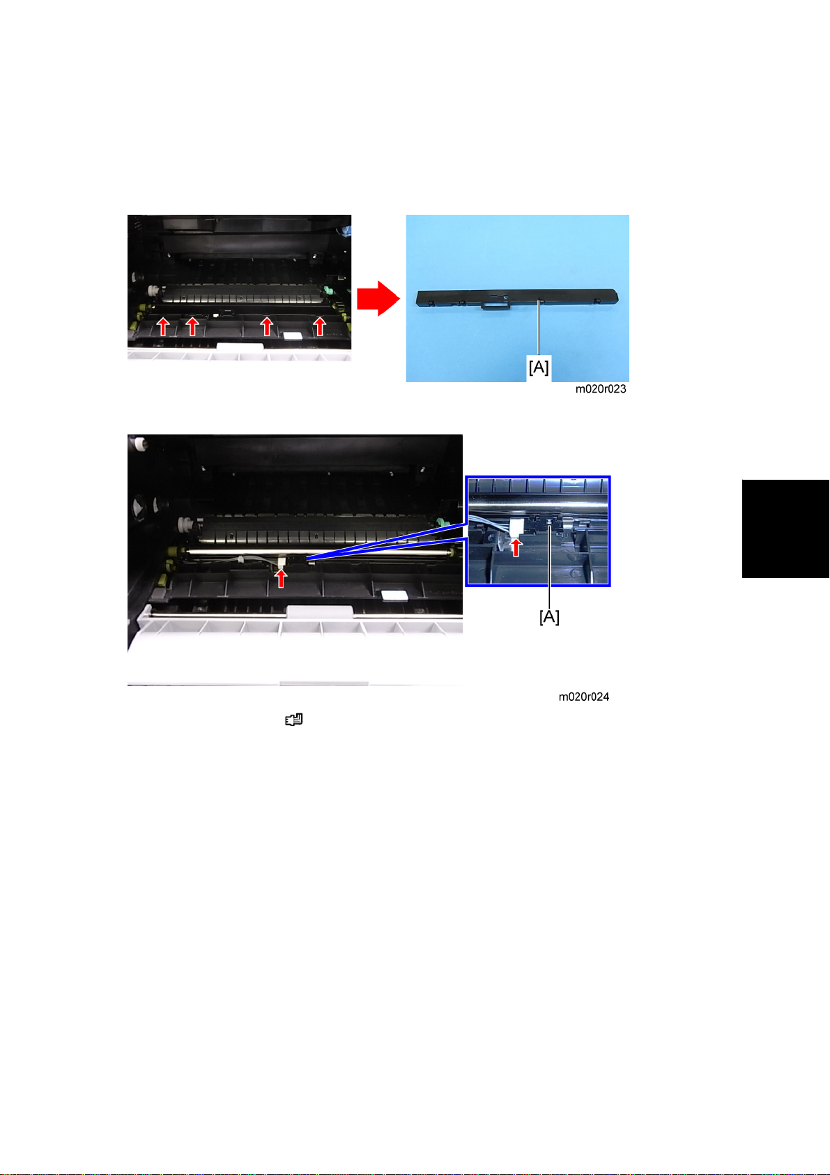
4.6.5 REGISTRATION SENSOR
1. Open the Front cover.
2. AIO unit.
3. Sensor cover [A] (Hooks x 4).
Paper Feed
4. Registration sensor [A] (
x 1).
and
Adjustment
Replacement
SM 4-31 M020/M021
Page 97

By-pass Tray
4.7 BY-PASS TRAY
4.7.1 BY-PASS TRAY UNIT
1. Pull the standard paper tray out.
2. Open the by-pass tray.
3. Bend two hooks [A] inward slightly and release them.
4. Pull the by-pass tray [A] obliquely down and remove it.
M020/M021 4-32 SM
Page 98

4.7.2 BY-PASS FEED ROLLER
1. Left cover ( p.4-5)
By-pass Tray
2. Right cover (
3. Front cover (
4. Remove the AIO unit.
5. Engine board with bracket (
6. Paper guide [A] ( x 2).
p.4-3)
p.4-7)
p.4-50)
Replacement
and
Adjustment
7. Actuator [A].
8. By-pass feed clutch (
SM 4-33 M020/M021
p.4-63)
Page 99

By-pass Tray
9. By-pass feed roller [A] (
Before attaching the paper guide, confirm that the actuator and the by-pass feed roller
are installed securely and that they move smoothly.
[B] x 2, bushing x 2 [C]).
4.7.3 BY-PASS FRICTION PAD
1. By-pass feed roller ( p.4-33)
2. By-pass friction pad [A] (hooks x 2).
M020/M021 4-34 SM
Page 100

4.7.4 BY-PASS PAPER SENSOR
1. Left cover ( p.4-5)
By-pass Tray
2. Engine board with bracket (
3. By-pass feed clutch (
4. By-pass paper sensor [A] (Hooks x 3, x 1).
p.4-63)
p.4-50)
and
Adjustment
Replacement
SM 4-35 M020/M021
 Loading...