


REMKO RXD
RXD 260, RXD 350, RXD 520, RXD 680, RXD 1200
Ceiling cassettes
Operation · Technology · Spare parts
Issue GB – T10

Contents
Safety notes |
4 |
Environmental protection and recycling |
4 |
Warranty |
4 |
Transport and packaging |
5 |
Description of the equipment |
5 |
Combinations |
5 |
Operation |
6-11 |
Shutdown |
12 |
Care and maintenance |
12-13 |
Troubleshooting and customer service |
14-15 |
Installation instructions for qualified personnel |
15-16 |
Installation |
16-19 |
Condensation connection |
20 |
Electrical connection |
20-21 |
Electrical connection diagram |
21 |
Electrical circuit diagram |
22 |
Commissioning |
23 |
Unit dimensions |
23 |
Product illustration |
24-25 |
Spare parts lists |
24-25 |
Technical data |
26 |
These operating instructions should be read carefully prior to commissioning / operation of the equipment!
These instructions are part of the equipment and must always be kept in the vicinity of the installation or on the equipment
Made by REMKO
Subject to modifications; No liability accepted for errors or misprints!
3

REMKO RXD
Safety notes
Carefully read this manual before starting the unit for the first time. It contains useful tips, information  as well as hazard warnings to prevent injury or material damage
  . Non-observance of this manual may endanger persons, the environment as well as the equipment itself and will void any claims for liability.
■Store this manual as well as the refrigerant datasheet in the vicinity of the unit.
■The unit should only be set up and installed by qualified personnel.
■The setup, connection and operation of the unit and its components must be in
accordance with the operating conditions stipulated in this manual and comply with all applicable local regulations.
■Units designed for mobile use should be safely set up on a suitable floor and in a vertical position. Units designed for stationary use should only be operated in their permanently installed state.
■It is prohibited to make modifications or changes to equipment or components supplied by REMKO as this may cause malfunctions.
■Equipment and components should not be operated in areas where there is a heightened damage risk. Observe the minimum clearances.
■The electrical supply should be adapted to fulfil the requirements of the unit.
■The operational safety of equipment and components is only assured providing they are used as intended and in a fully assembled state. Safety devices should not be modified or bypassed.
■Do not operate equipment or components with obvious defects or signs of damage.
■All housing parts and openings, e.g. air inlets and outlets, must not be blocked by foreign items, fluids or gases.
■The equipment and components must be kept a safe distance from inflammable, explosive, combustible, aggressive and dirty areas or atmospheres.
■Persons coming into contact with equipment parts may suffer burns or injury.
■Installation, repair and maintenance work should only be carried out by authorised specialists. Inspection and cleaning can be performed
by the operator providing the equipment is not under voltage.
■Take appropriate hazard prevention measures when performing installation, repair or maintenance work or cleaning the equipment.
■The equipment or components should not be exposed to any mechanical stresses, extreme levels of humidity or direct exposure to sunlight.
Environmental protection and recycling
Disposal of packaging
All products are packed for transport in environmentally friendly materials. Make a valuable contribution to reducing waste and sustaining raw materials. Only dispose of packaging at approved collection points.
Disposal of old equipment
Our production facility is subject to continuous quality control. Only high-grade materials are processed, the majority of which are recyclable. Help protect the environment by only disposing of old equipment in accordance with local regulations and in an environmentally safe manner, e.g. through authorised disposal and
recycling specialists or at collection points.
Warranty
Prerequisite for any warranty claims is that the purchaser or his client has completely filled out the "warranty registration card" and commissioning report included with the unit at the time when the equipment was purchased and commissioned and returned these papers to REMKO GmbH & Co. KG. The warranty conditions are detailed in the "General terms and conditions". The contractual parties can also agree additional terms beyond the scope of the
above. In this case, first contact the contractual partner.
4

Transport and packaging
The equipment is shipped in sturdy packaging. Immediately check
the equipment on delivery and make a note of any damage or missing parts on the delivery note. Inform the forwarding agent and contractual partner.
No warranty can be assumed for later claims.
Description of the equipment
The indoor unit on the split-design combined room air conditioning units serves to extract heat from the indoor room being cooled. The outdoor component then expels this heat to the outside.
If combined heating/cooling units are operated as heaters, the heat absorbed by the outdoor component can be discharged by the interior unit into the room being heated.
The unit is designed for suspended ceilings with Euroraster dimensions. The cassette is hidden behind the suspended ceiling, only its cover is visible. It is operated via an infrared remote control.
The indoor unit consists of a fin vaporiser, vaporiser fan, regulation system and condensation pan. The indoor unit can be combined with REMKO outdoor components that provide sufficient cooling output. The outdoor component is controlled via the regulation of the indoor unit.
Condensation pumps and wired remote controls are available as accessories.
Schematic of refrigerant circuit

 Vaporiser fan
Vaporiser |
|
|
|
|
|
|
|
|
|
|
|
|
|
|
|
|
|
|
|
|
|
|
|
|
|
|
|
|
|
|
|
|
|
|
|
|
|
|
|
|
|
|
Connection to suction pipe |
|
|
|
|
|
|
|
|
|
|
|
|
|
|
|
|
|
|
|
|
|
|
|
|
|
|
|
|
|
|
|
|
|
|
|
|
|
|
|
|
|
|
||
|
|
|
|
|
|
|
|
|
|
|
|
|
|
|
|
|
|
|
|
|
|
|
|
|
|
|
|
|
|
|
|
|
|
|
|
|
|
|
|
|
|
||
|
|
|
|
|
|
|
|
|
|
|
|
|
|
|
|
|
|
|
|
|
|
|
|
|
|
|
|
|
|
|
|
|
|
|
|
|
|
|
|
|
|
||
|
|
|
|
|
|
|
|
|
|
|
|
|
|
|
|
|
|
|
|
|
|
|
|
|
|
|
|
|
|
|
|
|
|
|
|
|
|
|
|||||
|
|
|
|
|
|
|
|
|
|
|
|
|
|
|
|
|
|
|
|
|
|
|
|
|
|
|
|
|
|
|
|
|
|
|
|
|
|
|
|
|
|||
|
|
|
|
|
|
|
|
|
|
|
|
|
|
|
|
|
|
|
|
|
|
|
|
|
|
|
|
|
|
|
|
|
|
|
|
|
|
|
|
|
|
Connection to injection pipe |
|
|
|
|
|
|
|
|
|
|
|
|
|
|
|
|
|
|
|
|
|
|
|
|
|
|
|
|
|
|
|
|
|
|
|
|
|
|
|
|
|
|
|
|
|
|
|
|
|
|
|
|
|
|
|
|
|
|
|
|
|
|
|
|
|
|
|
|
|
|
|
|
|
|
|
|
|
|
|
|
|
|
|
|
|
|
|
|
|
|
|
|
|
|
|
|
|
|
|
|
|
|
|
|
|
|
|
|
|
|
|
|
|
|
|
|
|
|
|
|
|
|
|
|
|
|
|
|
|
|
|
|
|
|
|
|
|
|
|
|
|
|
|
|
|
|
|
|
|
|
|
|
|
|
|
|
|
|
|
|
|
|
|
|
|
|
|
|
|
|
|
|
|
|
|
|
|
|
|
|
|
|
|
|
|
|
|
|
|
|
|
|
|
|
|
|
|
|
|
|
|
|
|
|
|
|
|
|
|
|
|
|
|
|
|
|
|
|
|
||
System design |
|
|
|
|
|
|
|
|
|
|
|
|
|
|
|
|
|
|
|
|
|
|
|
|
|
|
|
|
|
|
|
|
|
|
|
|
|
|
|
|
|
||
Indoor area |
Condensation |
|
|
|
|
|
|
|
|
|
|
|
|
|
|
|
|
|
|
|
|
||||||||||||||||||||||
pipe |
|
|
|
|
|
|
|
|
|
|
|
|
|
|
|
|
|
|
|
|
|||||||||||||||||||||||
|
|
|
|
|
|
|
|
|
|
|
|
|
|
|
|
|
|
|
|
|
|
|
|||||||||||||||||||||
Indoor unit with |
|
|
|
|
|
|
|
|
|
|
|
|
|
|
|
|
|
|
|
|
|||||||||||||||||||||||
Cover |
|
|
|
|
|
|
|
|
|
|
|
|
|
|
|
|
|
|
|
|
|
|
|
|
|
|
|
|
|
|
|
|
|
|
|
|
|
|
|
|
|
||
|
|
|
|
|
|
|
|
|
|
|
|
|
|
|
|
|
|
|
|
|
|
|
|
|
|
|
|
|
|
|
|
|
|
|
|
|
|
|
|
|
|||
Control cable
|
|
|
|
|
|
|
|
Outdoor area |
|
|
|
Injection pipe |
|||
Outdoor component |
|
|
|
|
|
||
|
|
|
|
|
|
Mains cable |
|
|
|
|
|
|
|
||
|
|
|
|
|
|
Suction pipe |
|
|
|
|
|
Stop valve |
|||
Condensation pipe |
|
|
|
Liquefier fan |
|||
|
|
|
|||||
|
|
|
|
|
|
|
|
|
|
|
|
|
|
||
Refrigerant pipes are used to connect the indoor unit to the outdoor component.
Combinations
Cooling / heating
|
RXD 260 |
RXD 350 |
RXD 520 |
RXD 680 |
RXD 1200 |
RXS 261H |
• |
• |
|
|
|
RXS 351H |
|
• |
|
|
|
RXS 521H |
|
|
• |
|
|
RXS 681H |
|
|
|
• |
|
RXS 1200H |
|
|
|
|
|
Cooling |
|
|
|
|
|
|
|
|
|
|
|
|
RXD 260 |
RXD 350 |
RXD 520 |
RXD 680 |
RXD 1200 |
RXM 226 |
•• |
•• |
|
|
|
RXM 235 |
|
•• |
|
|
|
RXM 252 |
|
|
•• |
|
|
RXM 268 |
•• |
• |
|
|
|
RXM 326 |
|
|
|
||
RXM 335 |
•••• |
••• |
|
|
|
RXM 426 |
•••• |
|
|
|
|
RXM 435 |
|
|
|
|
5
REMKO RXD
Operation
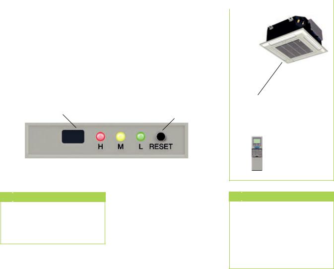
The indoor unit is easy to operate using an infrared remote control. This is supplied as standard. The indoor unit beeps to acknowledge the correct transmission of data. If it is not possible to program the indoor unit using the remote control, it can also be manually operated.
Manual operation |
Infrared remote control |
The indoor units can be started manually.
Press the RESET button on the receiver unit of the cover to activate automatic mode. In manual operation, the following settings apply:
Cooling mode: 24 °C,
Fan speed: AUTO
Heating mode: 26 °C,
Fan speed: AUTO
Pressing any button on the infrared remote control interrupts manual operation
The infrared remote control sends the programmed settings at a distance of up to 6 m to the receiver on the interior unit.
Data will only be received correctly if the remote control is pointed
at the receiver and no objects are obstructing the transmission path. First insert the supplied batteries (2 each, type AAA) into the remote control. To do so, remove the cover on the battery compartment and insert the batteries. Take into account the correct polarity (see markings).
Display on indoor unit |
|
Max. distance 6 m |
|
|
|
The lit display LEDs indicate the settings.
LED H red |
= |
high fan speed |
|
|
|
|
|
|
|
||
LED M yellow |
= |
medium fan speed |
|
|
|
|
|
||||
LED L green |
= |
low fan speed |
|
|
|
|
|
|
|
||
|
|
|
|
|
|
|
|
|
|
|
|
Display on indoor unit |
|
|
|
|
|
|
|
|
|
|
|
Unit for receiving signals |
LED |
LED |
LED |
RESET button |
|
max. 6 m |
|||||
|
|||||||||||
|
|
||||||||||
from the remote control |
H |
M |
L |
Manual operation |
|
|
|||||
|
|
|
|
|
|
|
|
|
|
|
|
|
|
|
|
|
|
|
|
|
|
|
|

 CAUTION
Problems are shown in code (see chapter on troubleshooting and customer service).

 Note
Note
Immediately replace flat batteries with a new set, otherwise there is a risk of leakage. It is recommended that the batteries are removed if the equipment is shut down for long periods.
6
|
|
|
|
|
|
|
|
|
|
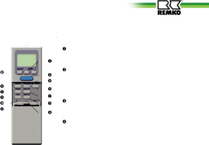
Buttons on the remote control |
Buttons on the remote control |
||||||||||
|
|
|
|
|
|
|
|
|
|
"POWER" button |
|
|
|
|
|
|
|
|
|
|
Press this button to start the |
|
|
|
|
|
|
|
|
|
|
unit. |
|
|
|
|
|
|
|
|
|
|
"TEMP" Button |
|
|
|
|
|
|
|
|
|
|
Press this button to set the |
|
|
|
|
|
|
|
|
|
|
|
|
|
|
|
|
|
|
|
|
|
desired temperature in 1 °C |
|
|
|
|
|
|
|
|
|
|
|
|
|
|
|
|
|
|
|
|
|
steps within the range 16 °C to |
|
|
|
|
|
|
|
|
|
|
|
|
|
|
|
|
|
|
|
|
|
30 °C. |
|
|
|
|
|
|
|
|
|
|
|
|
|
|
|
|
|
|
|
|
|
|
|
|
|
|
|
|
|
|
|
|
"TIME-SET" Button |
|
|
|
|
|
|
|
|
|
|
|
|
|
|
|
|
|
|
|
|
|
|
|
|
|
|
|
|
|
|
|
|
Press this button to set the |
|
|
|
|
|
|
|
|
|
|
time. |
|
|
|
|
|
|
|
|
|
|
|
|
|
|
|
|
|
|
|
|
|
"MODE" button |
|
|
|
|
|
|
|
|
|
|
Press this button to select the |
|
|
|
|
|
|
|
|
|
|
operating mode. The indoor unit |
|
|
|
|
|
|
|
|
|
|
has 5 modes: |
|
|
|
|
|
|
|
|
|
|
1. Automatic mode |
|
|
|
|
|
|
|
|
|
|
|
|
|
|
|
|
|
|
|
|
|
(COOL/HEAT): |
|
|
|
|
|
|
|
|
|
|
In automatic mode, the |
|
|
|
|
|
|
|
|
|
|
temperature is maintained at |
|
|
|
|
|
|
|
|
|
|
the target temperature. |
|
|
|
|
|
|
|
|
|
|
2. Cooling mode (COOL): |
|
|
|
|
|
|
|
|
|
|
In cooling mode, the warm |
|
|
|
|
|
|
|
|
|
|
room air is cooled to the lower |
|
|
|
|
|
|
|
|
|
|
preset target temperature. |
|
|
|
|
|
|
|
|
|
|
3. Dehumidifying mode (DRY): |
|
|
|
|
|
|
|
|
|
|
In this mode the room is mainly |
|
|
|
|
|
|
|
|
|
|
dehumidified. |
|
|
|
|
|
|
|
|
|
|
4. Circulation mode (FAN) |
|
|
|
|
|
|
|
|
|
|
In circulation mode only the |
|
|
|
|
|
|
|
|
|
|
air is circulated. The room |
|
|
|
|
|
|
|
|
|
|
temperature is not controlled. |
|
|
|
|
|
|
|
|
|
|
5. Heating mode (HEAT): |
|
|
|
|
|
|
|
|
|
|
(only for RXS...H) |
|
|
|
|
|
|
|
|
|
|
In heating mode the cold room |
|
|
|
|
|
|
|
|
|
|
air is heated to the preset higher |
|
|
|
|
|
|
|
|
|
|
temperature. |
|
|
|
|
|
|
|
|
|
|
This mode should not be used |
|
|
|
|
|
|
|
|
|
|
on RXM units (malfunctions may |
|
|
|
|
|
|
|
|
|
|
occur)! |
 "SWING" Button
This button switches on the oscillating fins to provide improved air distribution in the room. It can also be used to lock the fins.
 "FAN" button
Press this button to set the required fan speed. 4 levels are available: Automatic, high, medium and low fan speed.
 "TIME-OFF" Button
This button is used to program the automatic switch-off function for the indoor unit.
 "TIME-ON" Button
This button is used to program the automatic switch-on function for the indoor unit.
 "C" Button
Press this button to activate the time setting.
 "R" Button
Press this button to reset the remote control to its factory default configuration.
 "NETWORK" Button
This button has not been assigned a function.
 "SLEEP" Button
Pressing this button will automatically increase or decrease the target temperature by 1 °C within an hour in cooling and heating mode respectively.
7

REMKO RXD
Button functions
A symbol is shown on the display to indicate that the settings are being transferred.
POWER button |
Press the POWER button to activate/deactivate the indoor unit. The |
|
programmed settings and adjustment values before the unit was turned |
|
off will appear in the display. |
|
POWER |
TEMP button |
The TEMP button is used to set the desired target temperature in 1 °C |
|
|
steps. This setting is not supported in FAN circulation mode. |
|
|
TEMP |
TEMP |
|
Use a small pen or similar to press recessed button C, the time will flash |
time Button C |
|
|
on the display. Press and hold the TIME-SET button to, at first slowly, |
|
|
|
and then quickly adjust the clock time. Once it has been set, press the C |
|
button again to save the time. The display will stop flashing. |
|
C |
TIME-SET |
C |
|
|
|
Setting the clock |
RESET button R |
Use a small pen or similar to press recessed button R. All the symbols will |
||
|
appear on the display. After approx. 5 seconds only the time will flash on |
||
|
the display. After pressing recessed button C, press and hold the TIME- |
||
|
SET button to set the time. Once it has been set, press the C button |
||
|
again to save the time. The display will stop flashing. |
|
|
R |
5 sec. |
C |
8
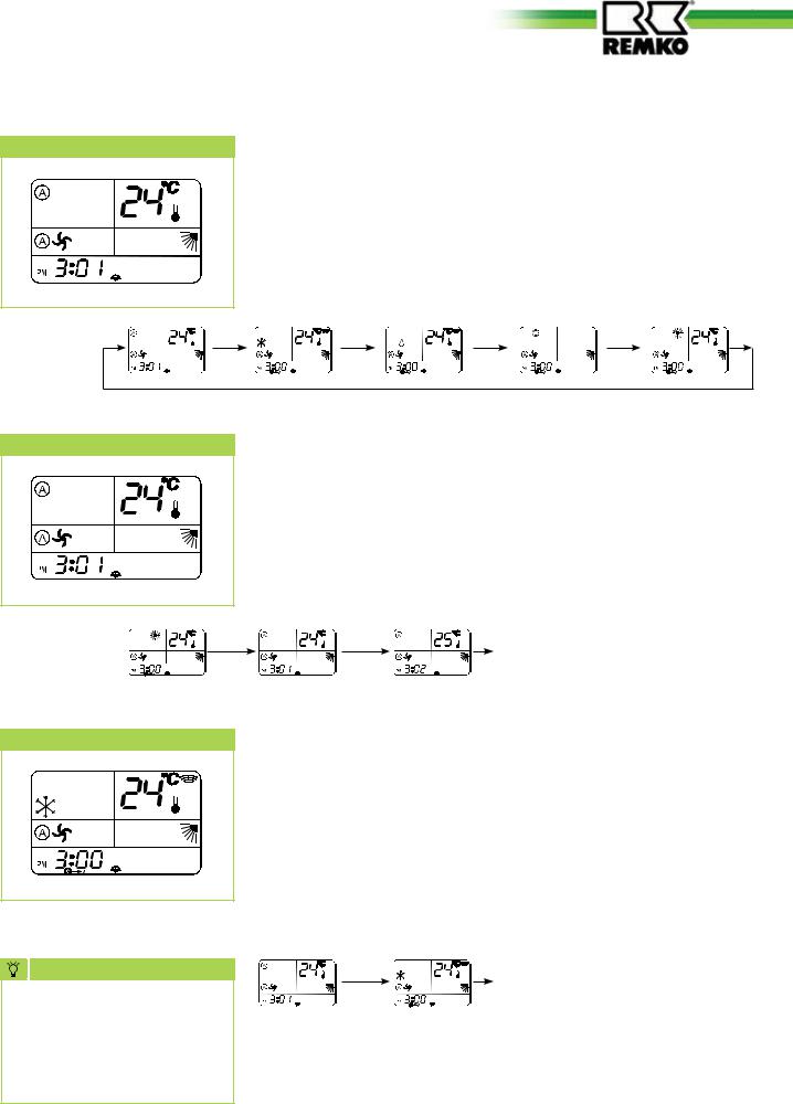
MODE button
Mode Auto
Mode Cool
Press the MODE button to change to another mode. A total of 5 modes are available:
1. |
Automatic |
Automatic selection of cooling or heating operation |
2. |
Cooling |
Cooling mode, predominantly used during summer |
3. |
Dehumidification |
Dehumidifying mode, used in summer or winter |
4. |
Air circulation |
Circulation mode, no cooling or heating output |
5. |
Heating |
Predominantly used during winter (only for RXS...H) |
MODE |
MODE |
MODE |
MODE |
Press the MODE button once or repeatedly to switch to automatic mode. In this mode, the regulation automatically selects COOL or HEAT mode depending on the temperature. The temperature is then maintained at the set value. This function should only be used on RXS...H units. Only cooling mode is activated on RXM units; heating mode is not supported. The FAN should be set to AUTO.
|
TEMP |
Set temperature is below the |
|
MODE |
COOLING room temperature |
||
|
|||
|
|
or |
HEATING Set temperature is above the room temperature
Press the MODE button once or repeatedly to switch to cooling mode. Use this mode to cool the room air to the desired target temperature.
Press the TEMP ▲/▼ buttons to set the desired room temperature in 1 °C steps. If the room temperature is 1 °C above the desired
temperature and sufficient coolant is available, the indoor unit will start to cool the room air. f the actual temperature falls approx. 0.5 °C below the set room temperature, the controller switches the cooling off.
TIP |
MODE |
Cooling mode |
It is recommended that the |
|
|
|
|
|
target temperature is set to |
|
|
max 6 °C below the outdoor |
|
|
temperature. The automatic |
|
|
fan speed and swing functions |
|
|
should also be used. |
|
|
9
 Loading...