


REMKO CMF / CMT
INVERTER HEAT PUMPS
Installation Manual
Edition D – V02/09 2-3

Contents
Safety notes |
4 |
Heat pump general |
5-9 |
Installation instructions |
10-13 |
Hydraulic connection |
14-15 |
Electrical connection |
15-22 |
Connection of refrigerant lines |
23 |
Commissioning |
24-31 |
Care and maintenance |
32 |
Troubleshooting |
33-35 |
Unit dimensions |
36-37 |
Characteristic curves |
38-40 |
General terms |
41-42 |
Technical data |
43 |
Carefully read these installation instructions prior to commissioning using the equipment!
These instructions are part of the unit and must always be stored in immediate vicinity of the placement location or on the unit.
Made by REMKO
Subject to modifications; No liability accepted for errors or misprints!
3
REMKO CMF / CMT
Safety notes
These instructions are to be read through carefully before installing the device. They contain useful tips and information, which are 
designated by. Warning information designed to prevent risks to persons and property are highlighted by
 Non-observance of this manual may endanger persons, the environment as well as the equipment itself and will void any claims for liability.
■These instructions must be stored in the immediate vicinity of the device.
■The unit and components may only be set up and installed by qualified personnel.
■The setup, connection and operation of the unit and its components must be undertaken in accordance with the operating conditions stipulated in this manual and comply with all applicable local regulations.
■It is prohibited to make modifications or changes to equipment or components supplied by REMKO as this may cause malfunctions and will lead to loss of any possible claims for liability.
■The equipment and components should not be operated in areas where there is a heightened risk of damage. Observe the minimum clearances.
■The electrical supply should be adapted to fulfil the requirements of the unit.
■The operational safety of the equipment and components is only assured providing they are used as intended and in a fully assembled state. Safety devices may not be modified or deactivated.
■Operate of equipment or components with obvious defects or signs of damage is prohibited.
■All housing parts and device openings, e.g. air inlets and outlets, may not be blocked by foreign items, fluids or gases.
■The equipment and components must be kept at a safe distance to inflammable, explosive, combustible, aggressive and dirty areas or atmospheres.
■Contact with equipment parts or components can lead to burns or injury.
■Installation, repair and maintenance work should only be carried out by authorised specialists. Inspection and cleaning can be performed by the operator providing the equipment is not live.
■Appropriate hazard prevention measures are to be taken when performing installation, repair or maintenance, or cleaning work on the equipment.
■The room must be properly ventilated before re-starting the equipment in the event that refrigerant leaks out from the indoor unit. Otherwise there is danger of suffocation.
■Tripped circuit breakers may only be replaced by similarly constructed models.
■The units must be inspected by a service technician at least once annually.
■In case of defects that endanger the operational safety of the unit, operation must be discontinued.
■The units may only be installed at the points provided for this purpose on site.
■The devices may only be attached to load-bearing structures or walls.
■Regulations such as the regional building regulations and the Water Ecology Act must be maintained.
4
Heat pump general
Economical and environmen- tally-conscious heating
The burning of fossil-based energy sources in order to generate power creates severe consequences for the environment. A high percentage of fossil fuels is also problematic due to the limited resources of oil and gas and the price increases resulting from this. For this reason, many people today are thinking both economically and environmentallyconsciously in terms of heating.
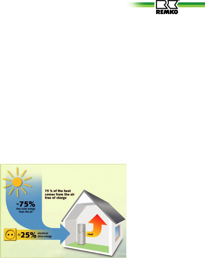
The application of heat pump technology enables both of these concepts to be combined. It makes use of the energy which is permanently available in the air, water and soil and converts it into usable heating energy by means of inputting electrical energy.
However, in order to generate a heat content of 4kW, it is only necessary to input approximately 1kW of electricity. The rest is made available free-of-charge by the environment.
Heat sources
There are essentially three heat sources that heat pumps can derive energy from. These are air, soil and groundwater. The air heat pumps have the advantage that the air source is available everywhere are in unlimited amounts an that it can be utilised free-of-charge. A disadvantage is that the outside air is at its coldest when the heat requirement is greatest. Brine heat pumps extract energy from the soil.
This is undertaken in serpentine pipe networks which are laid approx. 1m deep or placed by means of drilling. The disadvantage is the large space requirements for the serpentine pipe networks or the high cost of drilling. A permanent cooling of the soil is also possible.
Water heat pumps require two wells in order to obtain heat from the groundwater, one supply well and one dry well. The development of this source is not possible everywhere, it is expensive and requires planning permission.
Arguments for REMKO
■Low heating costs in comparison to oil and gas
■Heat pumps represent a contribution to environmental protection
■Lower CO2 emissions in comparison to oil and gas heating
■Numerous models are able to cool as well as heat
■Low noise level of the outdoor unit
■Flexible erection due to split system design
■Negligible maintenance costs
5
REMKO CMF / CMT
A heat pump is a device which makes use of a working medium to absorb ambient heat under low temperatures and transports this heat to a place where it can be
of use for heating purposes. Heat pumps work according to the same principles as a refrigerator. The difference is that the "waste product" of the refrigerator, the heat, is the goal in this case.
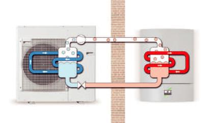
The main components of the refrigeration circuit consist of an evaporator, compressor, liquefier and expansion valve.
Finned evaporators serve to evaporate the refrigerant at low pressure even at low heat source temperatures, thereby absorbing the ambient energy. In the compressor, the refrigerant is compressed to a higher pressure by means of applying electrical energy, thereby increasing it up the correct temperature level.Afterwards the hot refrigerant gas reaches the liquefier, a plate heat exchanger.
Here the hot gas condenses and releases its heat to the heating system.The liquefied refrigerant is
then decompressed and cooled in a flow regulator, the expansion valve. Subsequently, the refrigerant flows back into the evaporator and the circuit is completed.
A heat pump manager is used in order to control the process, which in addition to all safety functions also provides fully automatic operation. The water circuit for the CMF Series indoor units includes a circulation pump, a plate heat exchanger,
dirt trap, safety valve, manometer, filling and drain valve, automatic deaerator and flow monitor.The CMT Series is additionally equipped with a diaphragm expansion vessel, a three-way switching valve and a storage tank.
Wall and floor-mounted units, condensation pans, condensate trough heating, 3-way switching valves, overflow valves and additional sensors are available as accessories.
Functional diagram heating |
Outdoor area |
Indoor area |
inverter heat pump |
|
|
|
Condensing |
|
|
Evaporation |
Liquefaction |
|
Decompression |
|
Heat pump outdoor unit |
|
Heat pump indoor unit |
|
|
|
Heat pump modes
Heat pumps can work in various operating modes.
Monovalent The heat pump is the sole heating appliance in the building all year round.This mode is particularly suitable for heating plants with low supply water temperatures and is primarily used in combination with brine/water and water/ water heat pumps.
Single energy sourceThe heating system does not require a secondary heating boiler. The heat pump covers a large proportion of the required heating power. Occasionally, when it is extremely cold outside, an electrical booster heating system switches on in order to support the heat pump as required.
Bivalent parallel modeThe heat pump provides the entire heating energy down to a predetermined outdoor temperature. If the outdoor temperature falls below this value, a secondary heating appliance switches on in order to support the heat pump.
This may take the form of alternative operation with oil or gas-fired heating or regenerative operation utilising solar energy or wood fuel heating.
This mode is possible for all heating systems.
6
Layout
A precise calculation of the building's heating load according to EN 12831 is required for the design and dimensioning of a heating system.
However, approximate requirements can be determined based on the year of construction and the type of building. The adjacent table shows the approximate specific heating loads for a number of building types. The required heating system output can be calculated by multiplying the area to be heated with the given values.
Various factors have to be considered in order to achieve a precise calculation.The transmission heat requirement, the infiltration heat loss and an allowance for water heating comprise the total heating output which has to be provided by the heating system.
The total area of the floor surfaces, exterior wall windows, doors and roofing is required in order to determine the transmission heat requirement. In addition, information about the materials used in the building is required, as these lead to extremely varied thermal transmission coefficients (the so called
K value). Also required is the room temperature and the average low, the lowest average outdoor temperature of the year.
The formula for determining the transmission heat requirement isQ=A U (tR-TA) and this must be calculated individually for the areas surrounding all rooms.
The infiltration heat requirement takes into consideration how often the heated room air is exchanged for cold external air. The room volume V, the air exchange frequency n and the specific heat capacity of the air is also required in addition to the room temperature and average
Building type
Passive energy house
Low-energy house built in 2002
according to energy conservation order regarding heat insulation 1995
Modern building constructed around 1984
Partially renovated old building constructed pre-1977
Non-renovated old building constructed pre-1977
Specific heating output in W/m2 approx. 10
approx. 40
approx. 60
approx. 80
approx. 100
approx. 200
low temperature. The formula for this is Q=V n c (tR-tA).
An approximate allowance for water heating per person amounts to 0.2 kW according to VDI 2067.
A residential home comprised of 160m² living-space and a heat requirement of 40 W/m² has been selected for the example design. A total of five persons live in the house. The heating load amounts
to 160m2 40W/m2=6,400W. Adding a drinking water allowance of 1 kW results in a required heating power of 7.4kW.
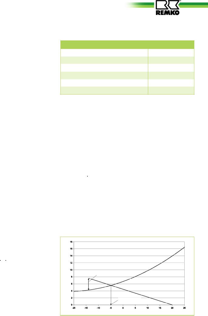
The dimensioning of the heat pump is given graphically on the diagram below together with the outdoor- temperature-dependent building heat requirements and the heating capacity characteristics for the heat pump.
The diagram with the heating capacity characteristics shows a simplified linear heating requirement.
A connecting line is drawn from the desired room temperature (20°C) and the point where the average low outdoor temperature (local low for the year) and the heat requirement meets (in this case: -14°C and 7.4kW). The intersection of the two curves are plotted on the X axis and the temperature of the balance point is read off. In this case it is -5°C.
The size of the submersion tube heater is the difference between the maximum heat requirement on the coldest days of the year and the heating output on these days. In the example, the required output is 7.4kW – 4.7kW = 2.7kW.
Heating capacity in kW
Necessary additional power
Bivalence point
Temperature in °C
7
REMKO CMF / CMT
Characteristics of REMKO inverter heat pumps
Heat source outdoor air
An air/water heat pump absorbs energy from the outdoor air as its heat source and transmits this to the heating system.They have the following advantages over a brine/ water and water/water heat pump system:
■Can be used everywhereAir is available everywhere in unlimited quantities. For example, no wells are required.
■No excavation work requiredNo large areas are required for soil collectors.
■EconomicalExpensive drilling is not required.
■Excellent value for money and simple installation
■Particularly suitable for lowenergy houses with low inlet temperatures
■Ideal for bivalent operation, in order to save energy
Split AC unit
The REMKO inverter heat pump is a so called split AC unit. This means that is consists of an outdoor unit and an indoor unit, both of which are connected via refrigerant-carry- ing copper pipes. This means that there are no water-carrying pipes laid from the indoors to outdoors which need to be made frost proof. The outdoor unit contains only the condenser, the evaporator and the expansion valve. This means that the outdoor unit is considerably smaller.
The indoor module contains the liquefier for the circuit and the connections for the heating network.
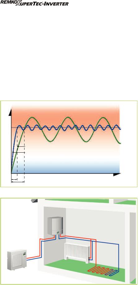
The heat pump's condenser is equipped with a requirement-de- pendent speed control system. The power control on conventional heat pumps provides only two states, either on (full power) or off (no power). The heat pump switches on when the temperature drops below a certain level and switches off again when this temperature has been reached.
This type of power control is extremely inefficient.The power control on REMKO'S inverter heat pumps is continuously modified to the actual heat requirement.
The electronics system has an integrated frequency converter which serves to modify the condenser speed and the speed of the evaporator fan as required. The condenser works at a higher speed when under full load as when it
is under partial load. The lower speeds ensure a longer operational lifetime for the components, improved coefficient of performance and lower noise.
Lower speeds also result in lower energy consumption (electricity).
8

Defrost by circulation reversal |
Versions |
At temperatures under approx. 5°C atmospheric moisture freezes on the evaporator which can lead to the formation of an ice layer. This can cause the heat transfer from the air to the refrigerant and the air flow to be reduced.
In this case, the ice must be removed. A four-way valve serves to reverse the refrigerant circuit, so that the hot gas from the compressor flows through the original evaporator and the ice that has formed there can melt.
The defrost process is not initiated after a predetermined time, rather it is carried out as required in order to save energy.
We offer two different indoor unit designs.
The wall-mounted CMF Series is equipped with a circulation pump and a safety module on the upstream face. In addition, an electrical heating coil can be integrated. The CMT Series of indoor modules is additionally equipped with a storage tank and an expansion vessel. The storage tank has a capacity of 150 litres.
We recommend an external storage tank for the CMF Series in order to avoid short operating times for the heat pump and in order to ensure that sufficient energy is available to bridge off-periods.
Cooling mode with models CMF 90, CMF 150, CMT 100 and CMT 150
Due to the circulation reversal system, a number of REMKO inverter heat pump models also offer cooling operation.
Cooling mode utilises the refrigerant components in order to produce cold water, in order that heat can be removed from the building.
This can either take the form of dynamic cooling or passive cooling.
Under dynamic cooling the refrigerating capacity is actively transferred to the indoor air. This is undertaken by means of waterbased fan convectors. In doing so, it is desirable that the inlet temperatures are under the dewpoint, in
order to transfer a higher refrigerating capacity and to dehumidify the indoor air.
in % |
|
|
Uneasily humid |
||
Relative air humidity |
|
|
|
|
|
|
|
Comfy
Still comfy
Uneasily dry
Room air temperature in °C
The comfort zone shows which values for temperature and humidity are considered comfortable for people. This range should ideally be met when heating or air-conditioning buildings.
Passive cooling refers to the absorption of heat via cooled floors, walls or ceiling surfaces. In doing so, water-carrying pipes make the structural sections into thermically effective heat exchangers. In order to achieve this, the refrigerant temperature has to lie above the dewpoint, in order to avoid the formation of condensation. Dewpoint monitoring is required for this purpose.
We recommend dynamic cooling with fan convectors, in order to achieve increased thermal performance and in order to dehumidify the air on muggy summer days. The advantage here is that dewpoint monitoring is not required.
9
REMKO CMF / CMT
Installation instructions
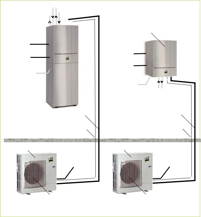
System design
The indoor and outdoor modules |
A four-wire control cable has to be |
|
have to be connected with refrigerant |
laid between the two modules. |
|
lines of dimensions 3/ " and 5/ ". |
|
|
8 |
8 |
|
Both the indoor and outdoor modules require a separate power supply.
|
|
Hot water 1" |
|||
Indoor area |
|
Domestic water 1" |
|||
Domestic water 1" |
|||||
Indoor |
|
|
|
Indoor module |
|
|
|
|
|||
|
|
|
|||
|
|
|
|||
|
|
|
|||
|
|
|
|||
module CMT |
|
|
|
||
Series |
|
|
|
|
CMF Series |
|
|
||||
Mains cable |
|
|
|
|
|
Interior 3x |
|
|
|
|
|
|
|
|
|
|
Mains cable |
Mains cable |
|
|
|
Interior 3x |
|
Electric heating |
|
|
|
optional mains |
|
230V or 400V |
|
|
|
power line |
|
Draining pan |
|
|
|
Electric heating |
|
|
|
|
|
|
230V or 400V |
|
|
|
|
|
Condensation line |
Hot water 1"
Refrigerant lines 3/ |
8 |
" and 5/ |
8 |
" |
Refrigerant lines 3/ |
8 |
" and 5/ |
8 |
" |
|
|
|
|
|
|
||||
electrical connection |
electrical connection |
||||||||
|
|
4x |
|
|
4x |
||||
Outdoor unit |
|
|
|
|
Outdoor unit |
|
|
|
|
* Mains supply |
|
|
* Mains supply |
|
|
||||
3x230V/1~/50Hz 25A |
3x230V/1~/50Hz 25A |
||||||||
|
|
fan |
|
|
fan |
Condensate drain |
Condensate drain |
||||
(must be designed to be frost proof!) |
(must be designed to be frost proof!) |
||||
Outdoor area
* Mains power supply 5x for outdoor modules CMF 140, CMF 150 and CMT 150: 400V/3~N/50Hz 16A
10
General Information |
Wall breakthroughs |
■These instructions are to be observed when installing the entire system.
■The device should be delivered as near as possible to the site of installation in its original packaging in order to avoid transport damage.
■The device is to be checked for visible signs of transport damage.
Possible faults are to be reported immediately to the contractualpartner and the haulage company.
■Suitable sites for installation are to be selected.
■The stops valves for the refrigerant lines may only be opened immediately before commissioning of the system.
 CAUTION
 CAUTION
■Special precautions relating to the oil return are to be met
if the outdoor component is located above the indoor unit (please refer to the "Connection of Refrigerant Lines" section).
■Add refrigerant if the basic length of the refrigerant pipe exceeds 30 meters.
■Establish all electrical connections in accordance with the relevant DIN and VDE standards.
■The electrical power cables must be fastened in a proper manner with electrical terminals.Otherwise there is a risk of fire.
■A wall breakthrough of at least 70 mm diameter and 10 mm slope from the inside to the outside must be created.
■The interior of the breakthrough is to be padded, e.g. with a cladding PVC pipe in order to avoid damage (see figure).
■After installation has been completed, use a suitable sealing compound to close off the wall breakthrough under observation of fire protection regulations (responsibility of customer).
 CAUTION
11

REMKO CMF / CMT
Installation of the indoor unit
Indoor module CMF Series
■The wall bracket is to be fastened to the wall with the supplied fastening materials and the indoor module hooked on.
■The wall must possess sufficient load-bearing capacity for the weight of the indoor module.
■Ensure that the wall bracket is installed level.
■The indoor module can be aligned precisely by means of the adjustment screws on the rear side of the housing.
■The indoor module is to be mounted in such a way that all of the sides have sufficient space for purposes of installation and maintenance.It is equally important that there is sufficient space above the device for installing the safety module.
NOTE
Only fixing materials which are suitable for the given application may be used.
Indoor module CMT Series
■The indoor module must be installed on a firm, level surface.
■The surface must possess sufficient load-bearing capacity for the weight of the indoor module.
■The height-adjustable feet can be used to precisely align the indoor module.
■The indoor module is to be mounted in such a way that all of the sides have sufficient space for purposes of installation and maintenance.It is equally important that there is also sufficient space above the device for installing the pipes and safety module.
12

Installation of the outdoor module
■The device may only be attached to a load-bearing construction or wall.
■Install the device on floor consoles with vibration dampers to minimise noise.
■The specified minimum clearances should be maintained when carrying out the installation. These protective zones serve to ensure unrestricted air inlet and outlet. It must be ensured that there is sufficient space available for installation, maintenance and repairs.
■The site of installation should be well ventilated.
 CAUTION
■If the outdoor module is erected in an area where there is strong wind, then the device must be protected from the wind. The snow line is to be observed during installation (see figures).
■It is to be ensured that the outdoor module is only installed vertically.
■The outdoor module is attached by means of 4 screws with vibration dampers on floor consoles.
Vibration dampers must also be used when installing the equipment with a wall bracket. The vibration dampers serve to reduce the noise transmittance.
■The Water Ecology Act is to be observed.
■A heatable condensate catch pan ensures that condensation from the pan is able to drain off.It must be ensured that the condensation water is frost-pro- tected in order that it can drain off (gravel, drainage).
Air intake
Air outlet
|
CMF 80 / CMF 90 / CMT 100 |
CMF 140 / CMF 150 / CMT 150 |
|
|
|
A |
min. 50 mm |
min. 50 mm |
B |
min. 750 mm |
min. 1,000 mm |
C |
min. 150 mm |
min. 150 mm |
D |
min. 250 mm |
min. 500 mm |
E |
min. 100 mm |
min. 100 mm |
|
|
|
Wind
Snow
20 cm
The right-hand side wall of the device is to be removed before installing the electrical cables and the refrigerant line to the outdoor module. In order to do so, release the three screws on the side wall and pull the panel downwards. If there is insufficient room underneath the device for the refrigerant lines, then the precut recesses can be removed from the lower enclosure panel and the pipes can be guided in through these openings.
13
REMKO CMF / CMT
Hydraulic connection
NOTE
A separate installation must be carried out for every system.
■For models CMF 80, CMF 90 and CMT 100 it must be ensured that the condenser pump flow rate always amounts to 1,400 l/h. For models CMF 140, CMF 150 and CMT 150 the flow rate must amount to 2,200 l/h. The indoor module components are designed for these flow rates.
■A hydraulic splitter or storage tank is to be used in order to separate the system circuits.
■A pipeline network connection must be undertaken before installing the heat pump.
■Floor heating systems must be protected against excessively high and low inlet temperatures.
■The pipe diameters for the supply and return connections of the heat pump may not be reduced before the connection of a system separation.
■Air bleed valves and drain-off taps must be planned for in suitable areas.
■The complete pipe network for the system must be flushed before connecting the heat pump.
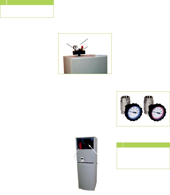
■The safety module contained in the scope of delivery comprises of a manometer, air vent and safety valve. It is to be mounted on the pipe connection for the indoor module.
Automatic deaerator
Manometer
Safety valve
Indoor unit
■An expansion vessel must be designed for the entire hydraulic system. The expansion vessel for the CMT range has a volume of 12 litres and is only intended to protect the storage tank and not for the entire pipe network of the hydraulic system.
■The system pressure of the entire pipe network is to be matched to the hydraulic system and must be checked when the heat pump is in a non-oper- ative state.
■In order to reduce the heating cycles to a minimum, it must be ensured that the heating load from the heat pump is fully transferred to the heating system.
■The supplied stop cocks are to be positioned directly at the connections for the heat
pump inlet and return lines. The shut-off valves each contain a thermometer with gauge.
|
Manual- |
Expansion- |
deaerator |
|
|
vessel |
|
|
|
CAUTION
Turning the thermometer heads serves to close or open the stop valves!
■The dirt traps should be installed outside of the heat pump in the return line.
14
 Loading...