


REMKO
HEAT PUMP MANAGER MULTI-TALENT
Manual for experienced specialists
Edition GB – B07

Contents
Safety notes |
4 |
Environmental protection and recycling |
4 |
Warranty |
4 |
Transport and packaging |
4 |
Intended use |
4 |
Function |
5 |
Heating curves |
6-7 |
Commissioning |
8 |
Menu structure / menu navigation / terminal configuration |
9 |
Menu structure / menu navigation / regulator configuration |
10-46 |
System selection / hydraulic diagram |
47-63 |
Merlin I/O circuit board contact layout |
64-65 |
DIP-switches / reset to factory setting |
65 |
Troubleshooting and customer service |
66-67 |
Sensor values / characteristic curve |
68 |
Technical data |
69 |
|
Read these operating instructions carefully |
|
before commissioning / using this device! |
|
These instructions are an integral part of the system and must always |
|
be kept near or on the device. |
Made by REMKO |
This operating manual is a translation of the German original. |
|
|
|
Subject to modifications; no liability accepted for errors or misprints! |
3

REMKO HEAT PUMP MANAGER
Safety notes
Read the operating instructions carefully before commissioning the equipment. They provide useful tips and information  as well as warnings to prevent endangering persons and property
  . Failure to follow the directions in this manual can result in endangerment to persons, the environment and the equipment itself and will void any claims for liability.
■Keep this manual close to the equipment.
■Modification of equipment and components supplied by REMKO is not permitted and can cause malfunctions.
■Operating equipment
or components with obvious defects or damage is not permitted.
■Repairs may only be carried out by authorised personnel, while cleaning may be carried out by the operating company.
■The equipment or components are not to be exposed to any mechanical stresses, extreme levels of humidity or direct sunlight.
Environmental protection and recycling
Disposal of packaging
All products are packed for transport in environmentally compatible materials. To avoid waste and sustain raw materials, dispose of packaging only at appropriate collection points.
Disposal of equipment and components
The equipment and components have been manufactured from recyclable materials
only.
Help protect the environment by ensuring that the equipment or components (for example batteries) are not disposed of with household waste but in an environmentally acceptable manner in accordance with applicable regulations, e.g. using authorised
disposal and recycling specialists or municipal collection points.
Warranty
A prerequisite for any warranty claims is that the enclosed "warranty registration card" was completely filled out and returned to REMKO GmbH & Co. KG by the buyer or his agent immediately following purchase or commissioning. The warranty conditions are listed in the "General terms and conditions". Special agreements can furthermore only be agreed between the contract partners. Please contact your contract partner directly about this.
Transport and packaging
The equipment is shipped in sturdy transport packaging. Please inspect the equipment immediately upon delivery. Note any damage or missing parts on the delivery note and inform the forwarding agent and your contract partner. Warranty claims at a later date will not be accepted.
Intended use
Depending on the model, the equipment and the additional fittings with which it is equipped is only intended to be used as an air-conditioner for the purpose of cooling or heating the air in an enclosed room.
Different or additional use shall not be classed as intended use. The manufacturer/supplier assumes no liability for damages arising from an unintended use of the equipment. The user bears the sole risk in such cases.
Using the equipment as intended also includes working in accordance with the operating manual and installation instructions and complying with the maintenance requirements.
4
Function
It is the function of the Multitalent heat pump manager to operate and effectively manage the entire warm water pump system including any additionally installed heating appliances. The multitude of functions provided by the heat pump manager must be configured in accordance with the existing heating system. This manual provides both installation instructions and a overview of what actually lies behind the heat pump manager's configuration parameters. The following functions are displayed in the heat pump manager:
•Heat pump operation
•Weather managed regulation of a direct heating circuit and a mixing circuit (e.g.: floor heating)
•Hot-water heating
•Cooling
•Solar function
•Demand oriented circulation pump switching
•Automatic summer/ winter time change
•Individually configurable reduction times and holiday operation for heating circuits and hot-water
•Cascade modulating heating appliance
•Cascade switching heating appliance
•Bivalence regulator
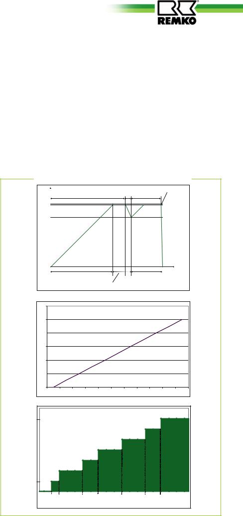
Control principles
Using an outdoor temperature sensor and the selected heating curve, the heat pump manager continuously establishes the target flow temperature and compares this temperature with the current system flow temperature (F8-T-Collector). The heat pump manager calculates the modula-
tion depth in % as a function of the difference between the current flow temperature and the target temperature. The modulation depth reflects the system's target output in %, for example the heat output made necessary by the current outdoor temperature.
The modulation depth is converted to a 0-10 V signal, whereby the outdoor unit of the heat pump is controlled..
[%] |
|
TSUPPLY ACTUAL > TSUPPLY TARGET |
TSUPPLY ACTUAL > TSUPPLY TARGET+ 2K |
||||
TSUPPLY ACTUAL < TSUPPLY TARGET |
|
|
|
TSUPPLY ACTUAL < TSUPPLY TARGET |
|||
depth |
100 |
|
|
|
|
|
|
|
|
|
|
|
|
|
|
Modulation |
98 |
|
|
|
|
|
|
80 |
|
|
|
|
|
|
|
WP modulating ON |
|
WP modulating ON |
WP OFF |
|
|
|
|
WP 100% +2. WE, if |
2. WE OFF |
||
|
|
|
|
Ta < bivalence point |
|
|
|
120 |
|
|
|
|
|
|
|
|
|
|
|
100 |
|
|
|
|
|
|
|
|
|
|
|
[%] |
|
|
|
|
|
|
|
|
|
|
|
depth |
80 |
|
|
|
|
|
|
|
|
|
|
|
|
|
|
|
|
|
|
|
|
|
|
Modulation |
60 |
|
|
|
|
|
|
|
|
|
|
40 |
|
|
|
|
|
|
|
|
|
|
|
|
20 |
|
|
|
|
|
|
|
|
|
|
|
0 |
|
|
|
|
|
|
|
|
|
|
|
0 |
1 |
2 |
3 |
4 |
5 |
6 |
7 |
8 |
9 |
10 |
|
|
|
|
0-10 V - signal output |
|
|
|
|
|
||
|
|
|
|
|
|
|
|
levelSt. 7 |
|
max |
|
|
|
|
|
|
|
|
performance |
|
|
|
|
|
levelSt. 6 |
|
|
|
|
|
|
levelSt. 55 |
|
|
|
|
|
|
|
|
level 4 |
|
|
|
|
pump |
|
|
|
St. 4 |
|
|
|
|
|
|
levelSt. 33 |
|
|
|
|
|
|
Heat |
|
|
|
|
|
|
|
|
|
levelSt. 22 |
|
|
|
|
|
|
|
levelSt. 1 |
|
|
|
|
|
|
|
|
min |
|
|
|
|
|
|
|
|
St. 0 |
|
|
|
|
|
|
|
0 |
2 |
2,5 |
4 |
5 |
6,5 |
8 |
8,8 |
10 |
|
|
|
|
|
00--10 V-signalSignal |
|
|
|
5

REMKO HEAT PUMP MANAGER
Heating curves
The heating curve is used for the purpose of assigning the building and appropriate target supply temperature in accordance with the outdoor temperature. The heating curves 0.2 to 0.8 have their base point at 20°C and are intended for surface heating. The heating
curves 1 to 3 have their base point at 27°C are therefore appropriate for radiator heating (steel radiators). The heating curve is easiest to set at outdoor temperatures below 5 °C. Changing the heating curve setting must be carried out in small steps and in larger time
intervals (at least 5 to 6 hours), because the system must first adjust to the new values after every change in the heating curve.
Target supply temperature in °C
Outdoor temperature in °C
6

Cooling
For the use of the cooling mode, the heat pump manager must be switched to "Cooling" mode (release of cooling mode). In addition, the basic parameters of cooling mode must be set to
"ON" and at least one of the two heating circuits must be switched to active for the cooling. The heat pump has a suitable cooling reservoir for the heating/cooling circuits through a cold water storage tank. This must take place with the hydraulic integration through a cold water storage tank (see hydraulic diagram).
Two-pipe system (combined heating/cooling circuit)
As a basic rule, it is possible to use the same circuit for both heating and cooling. In this case a suitable distribution system and a suitable single room controller must be present for cooling mode. One example of this is fan convectors. Cooling through floor heating or another surface system is possible. However, the cooling effect is lower, because no dehumidification of the room air can or may take place. In these situations the cooling return target temperature must be set high enough that the temperature cannot be expected to fall below dew point (see Specialist  Cooling mode T-RL Cooling)
 !
!
 ATTENTION
With the use of surface cooling, the cooling return target temperature must be set above the dew point (approx. 15 °C).
Four-pipe system (separate heating and cooling circuits)
The heat pump has an output for the connection of a cooling circuit pump and an output for the connection of a "cooling" switching valve. In the process, a separate cooling circuit can be created. With the use of fan
convectors, therefore, only cooling can take place in the summer.
Control algorithm
The control sensor for the cooling is the return sensor F17.
A command/release of the cooling can only take place from the heating circuit which is activated for the cooling. This can be both weather-controlled and room- temperature-controlled or can take place with a combination of these two types of regulation.
Weather-controlled release of cooling mode:
Cooling mode is started when the temperature falls below the target outside temperature (see User
 Heating circuit 1/2 T-external Cooling). If the current outside temperature falls more than 1K below this target value, the cooling function is stopped.

 NOTE
NOTE
You achieve the best cooling effect with fan convectors
 see REMKO supplier assortment KWD-S, WLT-S and KWK. With these devices the air in the room is cooled, rotated and dehumidified. It should be noted that the pipes of the cooling circuit must have water-vapour-tight insulation because of the additional dehumidifying performance!
Room-temperature-controlled release of cooling mode:
The room-temperature-controlled release of the cooling is only possible with a digital remote control. Cooling mode is started when the temperature falls below the target room temperature (see User  Heating circuit 1/2 T-room Cooling). If the current room temperature falls more than 2K below this set value, the cooling function is stopped.
Combined release:
If weather-controlled and room- temperature-controlled cooling are activated, both release conditions must be fulfilled to start the cooling function.
Power level of the heat pump in cooling mode:
If the temperature at sensor F17 is not more than 2K warmer than the cooling return target temperature, the heat pump runs in cooling mode at a set power of 50% (5 V-signal or power level 4). With
a greater cooling load the heat pump switches to power level 7 (10 V signal or maximum power). For this purpose, sensor F17 must be at least 2K warmer than the cooling return target temperature. If this is reached at a later time, the heat pump switches back to 50% power and then switches off once the sensor F17 has become more than 2K colder than the cooling return target temperature (see Specialist  Cooling Mode T-RL cooling).
If a hot water requirement arises, the cooling is interrupted for the duration of the hot water heating. However, the cooling circuit continues to operate through the cooling water storage tank.
7
REMKO HEAT PUMP MANAGER
Commissioning
The heat pump manager serves to operate and control the entire plant.
The heat pump manager itself is operated by the control unit. The control console is connected to the basic device and is located behind the flap on the indoor module.
 !
!
 CAUTION
After a power failure etc., the previously programmed configuration can be accepted immediately by pressing the
F-button next to End. This also happens automatically after
a delay of 10 minutes.
■System 1 is pre-installed at the factory. After a reset of the heat-pump manager, the parameters for System 1 are loaded.
■ Carry out a thorough visual
Cinspection before the actual commissioning process.
■ Switch the supply voltage back
Bon.
■The following screen appears on the Multitalent display.
A
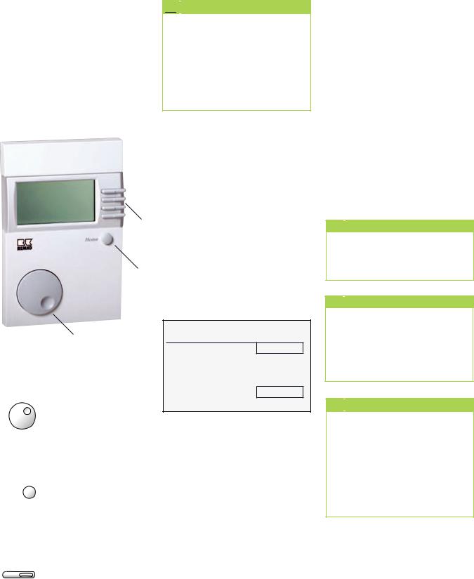
The control and display module of the heat pump manager is operated with the following keys.
The rotary knob (A) can be used to:
- move between the displayed menu items - change setting values
Home |
Pressing the Home but- |
|
ton (B) always returns |
||
|
||
|
you to the standard |
|
|
display. |
 Each of the four function
 keys (C) stands for one of
 the four rows on the display. Press one of these function keys to select
a menu item or setting value.
End
Installation
OK
■Determine which system diagram is to be used (see the hydraulic diagram in the appendix).
■If the System 1 schematic is applicable, you need only press the F-button next to End . Should a different system schematic be selected, press the F-button next to OK to begin installation.
■The configuration in the installation level for the selected hydraulics has to be completely programmed with
the parameters that go with it (see the hydraulic schematic in the heat-pump manager handbook).
■The system has to be matched to the customer's personal values (e.g. heating curve).
■The brief instructions supplied give an overview of how to set the most important values.
■After configuration, the system is to be run-in and the measured values are to be recorded in the commissioning report.

 NOTE
NOTE
Check the setting of Min. T-WW WE, idle time for accuracy. (see note P. 35).

 NOTE
NOTE
The commissioning and programming of the heat-pump manager may only be carried out by a mechanic authorised by REMKO.

 NOTE
NOTE
During commissioning, only
a typical heat-manager default setting can be carried out. Individual settings must be optimised for construction materials and the practices of various users. Especially during the first heating period.
8
Menu structure / Menu navigation / Terminal configuration
Level 0
|
|
Mo 30 Mar 09 08:30 |
|
|
|
|
T-external |
15.3 °C |
Home |
||
|
T-collector |
36.2 °C |
|||
|
|
||||
|
Automatic 1 |
|
|
|
|
|
|
|
|
|
|
Current operating mode (Operating mode)
Available modes:
-Stand by
-Cooling
-Automatic 1
-Automatic 2
-Summer
-Heating
-Reduction
-Service
(For a description of the operating modes, see page 16)
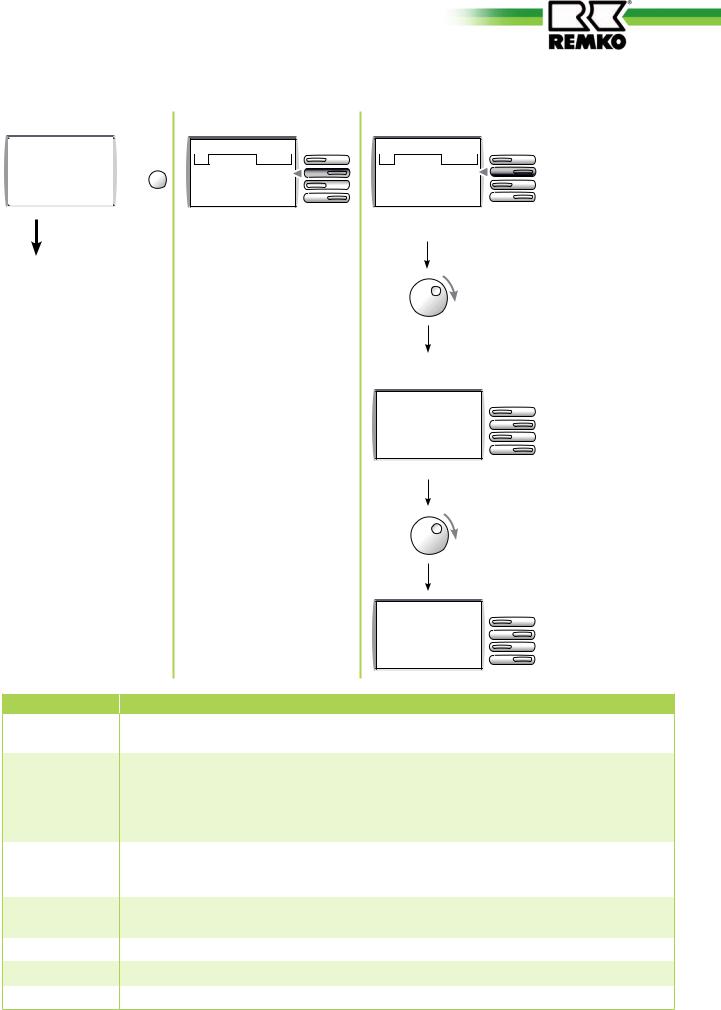
Level 1
Main menu
01 End
Terminal
Controller
Level 2 |
|
Terminal |
|
01 |
End |
Language |
English |
BUS code BM Off |
|
Terminal |
On |
By pressing the function key of the respective line you can reach change mode directly. The situation shown here in the example is if you want to change the language of the text display. Saving takes place after selection by pressing the function key on the line where it says OK.
Terminal
04 |
|
End |
|
Change code |
|
|
|
Communic Controller |
On |
||
E81-P Min |
|
80 |
|
Terminal
07 |
|
End |
E81-V Min |
---- |
|
Designation
Language
BUS code BM
Terminal
Change code
Communic Controller
E81-P Min
E81-V Min
Description
The following languages are available:
German, English, French, Dutch, Spanish, Italian
• OFF: Only operating function on the heat pump.
No additional controller active. No digital remote control present.
• 00-15: Number of the heating circuit for which the digital remote control should be activated. Address 01 must always be used for heating circuit 1 (direct heating circuit) and Address 02 must always be used for heating circuit 2 (mixing circuit).
Is always set to ON and cannot be changed. The controller/display unit is designated as Terminal (BM- T Control module -Terminal) Only a BM-T can be connected to the controller, which is why no address assignment is possible here.
The 4-digit code for changes of parameters in the Specialist level is shown here and can be changed. Note: Changing the code means that the Technical Support from REMKO is not longer available.
Is always set to ON and cannot be changed.
9

REMKO HEAT PUMP MANAGER
Menu structure / Menu navigation / Regulator configuration
|
Level 0 |
|
|
|
Level 1 |
|
|
|||||
|
|
|
|
|
|
|
|
|
|
|
|
|
|
|
Mo 30 Mar 09 08:30 |
|
Main menu |
|
|
||||||
|
|
|
|
|
|
|
|
|
01 |
|
End |
|
|
|
T-external |
15.3 °C |
Home |
Terminal |
|
|
|||||
|
|
T-collector |
|
36.2 °C |
Controller |
|
|
|||||
|
|
|
|
|
|
|||||||
|
|
Automatic 1 |
|
|
|
|
|
|
|
|
|
|
|
|
|
|
|
|
|
|
|
|
|
|
|
|
|
|
|
|
|
|
|
|
|
|
|
|
Current operating mode (Mode)
-Standby
-Cooling
-Automatic 1
-Automatic 2
-Summer
-Heating
-Reduction
-Service
Level 2
Controller
01 End
Display
User
Time programme
Controller
01 End
Display
User
Time programme
Controller
01 End
Display User
Time programme
Controller
04 End
Time-Date
Service
Specialist
Controller
04 End
Time-Date
Service
Specialist
Controller
04 End
Time-Date
Service
Specialist
Level 3
Display
01 End
Plant
Hot water
Heating circuit 1
Heating circuit 2
Solar / MF
User
01 End
Plant
Hot water
Heating circuit 1
Heating circuit 2
Time programme
01 End
Heating circuit 1 prog 1 Heating circuit 1 prog 2 Heating circuit 2 prog 1 Heating circuit 2 prog 2 Hot water
Circulation program WE 1 enable
WE 2 enable WE 3 enable WE 4 enable S-Kick enable PU night enable
Time-Date
01 End
Time
Date Holiday start Holiday end
Summer time setting start Summer time setting end
Service
01 End
Relay test Sensor test Software number
Manual cascade operation Burner running-time Burner starts
STB test Customer service
Reset user Reset specialist
Reset time programme Communication BM 1 Communication BM 2 Communication KM
Specialist
01 End
Configuration
Heating appliance Cascade
Heat pump Cooling mode 0-10V I/O Screed
Hot water Heating circuit 1 Heating circuit 2 Solar / MF
10
Level 4
DISPLAY
Plant |
Hot water |
Heating circuit 1 |
|
Heating circuit 2 |
01 |
End |
01 |
End |
01 |
End |
01 |
End |
T-external |
T-WW |
T-room |
T-room |
||
T-collector |
T-WW U |
T-supply |
T-supply |
||
T-WE |
WW demand |
Heating circuit enable |
Heating circuit enable |
||
WE status |
WW pump |
Heating circuit pump |
Heating circuit pump |
||
T-return total |
WW enable |
B-warm up-time |
B-warm up-time |
||
T-tank 3 |
|||||
Circulation pump |
|
|
|
||
Modgrad |
See page 14 |
See page 14 |
|||
|
|||||
Error |
See page 14 |
||||
|
|
|
|
||
See page 13
Solar / MF
01 End
MF 1
MF 2
T-MF 3
MF 3
MF 4
T-solar 1
T-WW
T-WW U
Solar pump 1
Load Sp WW
See page 14
USER
Plant
01 End
Operating mode Language
LCD contrast LCD brightness °C/°F
See page 15
Hot water
01 End
1 x hot water T-WW 1 target T-WW 2 target T-WW 3 target BoB value
Circ with WW prog Anti-legionella
See page 16
Heating circuit 1
01 End
Operating mode T-room target 1 T-room target 2 T-room target 3 T-reduction T-absent T-room cooling
T-external cooling Heating threshold day
Heating threshold night heating curve T-supply const T
T-supply const N Room impact
Heating curve adaptation Warm up opt
Max warm up-time Reduction opt
PC enable
Heating circuit 2
01 End
Operating mode T-room target 1 T-room target 2 T-room target 3 T-reduction T-absent T-room cooling
T-external cooling Heating threshold day
Heating threshold night heating curve T-supply const T
T-supply const N Room impact
Heating curve adaptation Warm up opt
Max warm up-time Reduction opt
PC enable
See page 16-19 |
See page 16-19 |
TIME PROGRAMME
Time programme
01 End
Heating circuit 1 prog 1 Heating circuit 1 prog 2 Heating circuit 2 prog 1 Heating circuit 2 prog 2 Hot water
Circulation program WE 1 enable
WE 2 enable WE 3 enable WE 4 enable S-Kick enable PU night enable
See page 20
TIME-DATE
Time-Date
01 End
Time
Date Holiday start Holiday end
Summer time setting start Summer time setting end
See page 21
SERVICE
Service
01 End
Relay test Sensor test Software number
Manual cascade operation Burner running-time Burner starts
STB test Customer service
Reset user Reset specialist
Reset time programme Communication BM 1 Communication BM 2 Communication KM
See page 22-23
11

REMKO HEAT PUMP MANAGER
Level 4 - continued
SPECIALIST
Configuration |
|
|
Heating appliance |
Cascade |
|
||||||
01 |
|
End |
|
|
01 |
|
End |
|
01 |
|
End |
|
|
|
|||||||||
Terminal address |
|
Max T-collector |
|
WE found |
|
||||||
Regulator address |
|
Min T-collector |
|
Output/level |
|
||||||
BUS code 1 |
|
|
Min T-WE 2 |
|
BUS scan |
|
|||||
BUS code 2 |
|
|
Hysteresis |
|
min mod cascade |
||||||
eBUS supply |
|
|
Hysteresis period |
WW-WE |
|
||||||
System selection |
|
Sequence change |
System deviation |
||||||||
Regulator type |
|
|
Clock inhibition |
|
Output target |
|
|||||
WE 1 type |
|
|
|
Remaining idle time |
|||||||
|
|
Hyst burner 2 |
|
||||||||
WE BUS |
|
|
|
Max T-WE |
|
||||||
|
|
Gradient |
|
|
|||||||
WE 2 type |
|
|
|
WE Dyn up |
|
||||||
|
|
Max reduction |
|
|
|||||||
WE 2 tank |
|
|
|
WE Dyn down |
|
||||||
|
|
Dyn shut-off |
|
|
|||||||
WE 3 type |
|
|
|
Reset time |
|
||||||
|
|
WE cooling function |
|
||||||||
WE 4 type |
|
|
Modgrad on |
|
|||||||
|
|
T-WE cold start |
|
|
|||||||
Buffer type |
|
|
|
Modgrad off |
|
||||||
|
|
|
|
|
|
|
|||||
Cooling mode |
|
|
|
See page 30-31 |
Min modgrad |
|
|||||
F 15 function |
|
|
|
Modgrad WW |
|
||||||
E 1 function |
|
|
|
|
|
|
WE sequence 1 |
||||
E 2 function |
|
|
|
|
|
|
WE sequence 2 |
||||
Sensor |
|
|
|
|
|
|
Sequence mode |
||||
|
|
|
|
|
|
|
|
Sequence change |
|||
See page 25-29 |
Clock inhibition |
|
|
|
See page 32-34 |
Heat pump
01 End
Max T-return Min T-return WP Max TA WE Min TA WP
E1 function
E2 function
F15 function Return offset Min T-WW Min T-PU WE
Max WE idle time Impulse rate Impulse unit
Min FlowVol
See page 34-35
Cooling mode
01 End
T-RL cooling Cooling off at WW
Cooling with WP
See page 35
0-10V I/O
01 End
SPG curve
Curve 11 U 1
Curve 11 U 2
Curve 11 T 1
Curve 11 T 2
Curve 11 U A
See page 36
Solar / MF
01 End
MF 1 function MF 2 function MF 3 function MF 4 function MF 4 Hyst MF 4 Hyst Off Max T-supply Min T-solar on Min T-solar off
T-solar protection Re-cooling difference Max T-SP WW
Max T-SP PU
Max T-SP 3
Solar kick duration Solar kick interval Solar kick gradient
See page 42-46
Screed |
|
|
Hot water |
|
|
Heating circuit 1 |
||||||||
|
01 |
|
End |
|
|
01 |
|
End |
|
|
01 |
|
End |
|
|
||||||||||||||
Screed |
|
|
Charge pump lock |
HC function |
|
|
||||||||
Screed programme |
PPL |
|
|
Operation HCP |
|
|
||||||||
|
|
|
|
|
T-WE WW |
|
|
Max T-supply |
|
|
||||
|
|
|
|
|
Hysteresis WW |
|
|
Min T-supply |
|
|
||||
|
|
See page 36 |
|
|
|
|
||||||||
|
|
WW lag |
|
|
T-supply cooling |
|||||||||
|
|
|
|
|
TH inlet |
|
|
T-frost protection |
||||||
|
|
|
|
|
Thermal function |
T-external delay |
||||||||
|
|
|
|
|
Charging |
|
|
|
|
|
|
|
||
|
|
|
|
|
|
|
|
|
See page 39-41 |
|||||
|
|
|
|
|
|
|
See page 37-38 |
|
|
|||||
|
|
|
|
|
|
|
|
|
|
|
|
|||
Heating circuit 2
01 End
HC function Operation HCP Mixer Open Mixer CLOSED Max T-supply Min T-supply T-supply cooling T-frost protection T-external delay
Curve displacement Demand requirement
See page 39-41
12

Level 4 - DISPLAY - Description of parameters and settings
DISPLAY
Plant |
Hot water |
Heating circuit 1 |
|
Heating circuit 2 |
01 |
End |
01 |
End |
01 |
End |
01 |
End |
T-external |
T-WW |
T-room |
T-room |
||
T-collector |
T-WW U |
T-supply |
T-supply |
||
T-WE |
WW demand |
Heating circuit enable |
Heating circuit enable |
||
WE status |
WW pump |
Heating circuit pump |
Heating circuit pump |
||
T-return total |
WW enable |
B-warm up-time |
B-warm up-time |
||
T-tank 3 |
|||||
Circulation pump |
|
|
|
||
Modgrad |
See page 14 |
See page 14 |
|||
|
|||||
Error |
See page 14 |
||||
|
|
|
|
||
See page 13
Solar / MF
01 End
MF 1
MF 2
T-MF 3
MF 3
MF 4
T-solar 1
T-WW
T-WW U
Solar pump 1
Load Sp WW
See page 14
Display of system values
Values cannot be changed in the display section.
There is a display only if the respective sensor is connected or the value exists in the system. If the setting does not exist, it is either hidden or dashes (----) are shown in the display.
Factory settings can vary depending on the system.
Plant
Designation |
Description |
|
|
T-external |
Current outdoor temperature [sensor 09] (smoothed value). |
|
Current collector temperature [sensor 08] and (collector) target temperature Display following pressing |
T-collector |
of the respective function key. |
|
The target corresponds with the highest temperature demanded in the load circuits (incl. water heating). |
T-WE |
Current temperature of all connected heating appliances [sensor 08]. |
WE status |
Heating appliance's status (on / off). |
T-return total |
Current temperature [sensor 17]. |
T-tank 3 |
Current temperature of the tank 3/buffer tank bottom [sensor 01]. No assignment by REMKO |
Modgrad |
Current target modulation depths for all active WE and required modulation depth. |
Error |
Error number (00 = no errors). |
|
|
Hot water
Designation
T-WW
T-WW U WW demand WW pump WW enable
Circulation pump
Description
Current hot water temperature [sensor 06] and after press the corresponding button hot water target temperature
Current temperature of the buffer tank bottom [sensor 12]
Status of heat demand hot water (on/off).
Status of the hot water charge pump (on/off) / or actuated 3-way switch valve. Enable water heating (on/off).
Circulation pump status (on/off).
13

REMKO HEAT PUMP MANAGER
Level 4 - DISPLAY - Description of parameters and settings - continued
Heating circuit 1/2
Designation
T-supply
Heating circuit enable Heating circuit pump B-warm up-time
Description
Current supply temperature [sensors 05/08] and supply target temperature following pressing of the respective function key.
Heating circuit in heating mode (on/off).
Heating circuit pump status (on/off).
Last required warm up-time with active warm up optimisation.
Solar / MF
Designation |
Description |
|
|
|
|
MF 1 |
Status of the relay MF 1 (on/off) outlet A8 - 2nd heating appliance. |
|
MF 2 |
Status of the relay MF 2 |
(on/off) outlet A9 - charge pump indoor unit. |
T-MF 3 |
Current temperature of the MF 3 sensor [sensor 13] - not used by REMKO. |
|
MF 3 |
Status of the relay MF 3 |
(on/off) outlet A10 - 3-way switch valve cooling / MP cooling |
MF 4 |
Status of the relay MF 4 |
(on/off) outlet A12 - solar-circulation pump. |
T-solar 1 |
Current collector temperature [sensor 14]. |
|
T-WW |
Current hot water temperature and hot water target temperature [sensor 6]. |
|
T-WW U |
Current temperature of the buffer tank bottom [sensor 12] (sensor collector system). |
|
Solar pump 1 |
Status of the collector pump (on/off). |
|
Load Sp WW |
Status of the tank charge pump 1 (on/off) not used by REMKO. |
|
|
|
|
14

Level 4 - USER - Description of parameters and settings
USER
Plant
01 End
Operating mode Language
LCD contrast LCD brightness °C/°F
See page 15
Hot water
01 End
1 x hot water T-WW 1 target T-WW 2 target T-WW 3 target BoB value
Circ with WW prog Anti-legionella
See page 16
Heating circuit 1
01 End
Operating mode T-room target 1 T-room target 2 T-room target 3 T-reduction T-absent T-room cooling
T-external cooling Heating threshold day
Heating threshold night heating curve T-supply const T
T-supply const N Room impact
Heating curve adaptation Warm up opt
Max warm up-time Reduction opt
PC enable
Heating circuit 2
01 End
Operating mode T-room target 1 T-room target 2 T-room target 3 T-reduction T-absent T-room cooling
T-external cooling Heating threshold day
Heating threshold night heating curve T-supply const T
T-supply const N Room impact
Heating curve adaptation Warm up opt
Max warm up-time Reduction opt
PC enable
See page 16-19 |
See page 16-19 |
Summary of settings that can be set by the system operator.
Plant
Designation |
Value range |
Factory setting |
Description |
|
||
|
|
|
Setting the operating mode / the operating mode for the |
|||
|
|
|
system. |
|
||
|
|
|
• Standby (heating OFF, water heating OFF, |
|||
|
|
|
only frost protection). |
|||
|
|
|
• Cooling (heating OFF, only water heating, activation of |
|||
|
|
|
the cooling machines, regulation of the heating circuits to |
|||
|
Standby |
|
T-supply cooling). |
|
||
|
|
|
|
|
||
|
Cooling |
|
• Automatic 1+2 (heating in accordance with the |
|||
|
Automatic 1+2 |
|
||||
Operating mode / |
|
heating programme 1/2, WW in accordance with WW- |
||||
Summer |
Standby |
|||||
programme). |
|
|||||
Operating mode |
|
|||||
Heating |
|
|
||||
|
|
• Summer (heating OFF, WW in accordance with WW- |
||||
|
Reduction |
|
||||
|
|
programme). |
|
|||
|
Service |
|
|
|||
|
|
|
|
|
||
|
|
|
• Heating (regulation to T-room target). |
|||
|
|
|
• Reduction (regulation to T-reduction). |
|||
|
|
|
• Service (Controller to Max T-WE, |
|||
|
|
|
see Specialist |
|
Cascade |
|
|
|
|
|
|||
|
|
|
The service mode automatically returns to the |
|||
|
|
|
previous operating mode after 15 min.. |
|||
Language |
D/GB/F/NL/E/I |
English |
Setting the language for the controller. |
|||
LCD contrast |
00-06 |
04 |
Setting the display intensity. |
|||
LCD brightness |
00-30 |
30 |
Setting the display lighting brightness. |
|||
°C/°F |
Celsius |
Celsius |
Setting the temperature unit. |
|||
Fahrenheit |
||||||
|
|
|
|
|
||
|
|
|
|
|
|
|
15

REMKO HEAT PUMP MANAGER
Level 4 - USER - Description of parameters and settings - continued
Hot water
Designation |
Value range |
Factory setting |
1xhot water |
On/Off |
Off |
T-WW 1 target |
10°C-70°C |
50°C |
T-WW 2 target |
10°C-70°C |
50°C |
T-WW 3 target |
10°C-70°C |
50°C |
BoB value |
0.0K-70.0K |
0.0K |
Circ with WW prog |
On/Off |
Off |
Anti-legionella |
On/Off |
Off |
|
|
|
Description
The tank is only enabled for a one time loading
(= ON) (e.g. for showering outside of hot water times). Loading only begins if the T-WW 1 target temperature has been undercut by the amount of the switching hysteresis (see specialist  hot water
  hysteresis WW)..
Setting the desired hot water temperatures for the hot water programme's 1st, 2nd and 3rd enabling times (see time programme  hot water).
Power saving function for solar or solid fuel boiler (operation without burner).
The burner is activated if the current hot water temperature in the amount of the set value here + switching hysteresis (see specialist  hot water
  hysteresis WW) has fallen below the set hot water target temperature.
Activating the circulation pump.
The circulation pump runs when hot water is enabled
(= ON), the circulation programme (see time programme
 circulation programme) has no impact.
Activating the anti-legionella function.
With every 20th heating or at least once a week (on Saturdays at 01:00) the tank is warmed to 65°C (= ON). It is possible to set a separate anti-legionella function e.g. by means of the 3rd hot water enabling time (see time programme  hot water).
Be submitted to activation of anti-legionella program must usually electric heating thermostat to 65 °C.
Heating circuit 1/2
Adjustable values can vary depending on the function selected for the heating circuit.
Designation
Operating mode
T-room target 1 T-room target 2 T-room target 3
T-reduction
Value range
----
Standby
Cooling
Automatic 1+2
Summer
Heating
Reduction
Service
5.0°C-40.0°C 5.0°C-40.0°C 5.0°C-40.0°C
5.0°C-40.0°C
Factory setting
----
20.0°C
20.0°C
20.0°C
15.0°C
Description
Setting the operating mode for the respective heating circuit.
 !
!
 CAUTION
If an operating mode is set here outside of "----", this operating mode will always apply for the respective heating circuit regardless of the operating mode setting in the main menu. This setting possibility is intended for the use of a remote control.
Setting of the desired room temperature for the 1st, 2nd and 3rd enabling times of the active heating programme in automatic 1/2 operating mode. A setting other than 20 °C causes a parallel shift of the heat curve on page 6.
Setting the desired room temperature during night reduction (time between heating periods, see time programme  heating circuit 1/2 prog 1/2).
16

Level 4 - USER - Description of parameters and settings - continued
Heating circuit 1/2-continued
Designation
T-absent
T-room cooling
T-external cooling
Heating threshold day
Heating threshold night
heating curve
Value range |
|
Factory setting |
5.0°C-40.0°C |
|
15.0°C |
|
||
----/20.0°C-40.0°C |
|
25.0°C |
0.0 -40.0°C |
|
20.0°C |
----/-5.0°C-40.0°C |
|
19.0°C |
----/-5.0-40.0°C |
|
10.0°C |
0,00-3,00 |
|
0,60 |
|
|
|
Description
Setting the desired room temperature during holiday reduction (time away) (see Time-Date  holiday start / end).
Setting the desired room temperature in cooling mode for the selected heating circuit.
The cooling operation is activated if the temperature set here is exceeded and ends if this temperature is undercut by 2K. Only in connection with a remote control. With the value "----", the cooling operation is independent of the room temperature.
Furthermore, the cooling operation must be enabled by T-external cooling.
The cooling operation is enabled and activated if the outdoor temperature exceeds the value set here and ends if this temperature is undercut by 1K.
These functions are only activated after the mode HKP in the specialist menu has been programmed to heating threshold.
Setting the heating threshold.
If the outdoor temperature measured and determined by the controller exceeds the heating threshold set here, the heating will lock, the pumps shut off and the mixers close.
The heating will be enabled again if the outdoor temperature undercuts the set heating threshold by 1K.
•Heating threshold day (operates during heating periods).
•Heating threshold night (operates during reduction periods).
At "----", the heating threshold is deactivated and the circulation pump will be switched in accordance with the standard function.
The curve's slope indicates by how many degrees the supply temperature will change if the outdoor temperature rises or falls by 1°C.
If during cold outdoor temperatures the room temperature is too low (too high), the heating curve must be raised (lowered).
If during high outdoor temperatures the room temperature is too low, the room temperature must be corrected by means of the room target temperature (parallel adjustment of the heating curve).
At "0.00", room regulation is active.
Changing the heating curve must be carried out in small steps and in larger time intervals (at least 5 to 6 hours), because the system must first adjust to the new values after every change in the heating curve.
17

REMKO HEAT PUMP MANAGER
Level 4 - USER - Description of parameters and settings - continued
Heating circuit 1/2-continued
Designation |
Value range |
Factory setting |
Description |
T-supply const T
T-supply const N
Room impact
Heating curve adaptation
Warm up opt
10°C-110°C
10°C-110°C
Off 00-20
On/Off
Off
T-room
T-external
35.0°C
10.0°C
Off
Off
Off
This function is only active once the HK function was programmed to T-feed const in the specialist menu.
Setting the desired supply temperature with which the selected heating circuit is operated during the heating period.
This function is only active once the HK function was programmed to T-feed const in the specialist menu.
Setting the desired supply temperature with which the selected heating circuit is operated during the reduction period.
This function is only activated with the analogue remote control (FBR-2).
The WE temperature is increased in the amount of the value set here if the desired room temperature (T-room target) is undercut by 1K (room sensor impact).
Automatic regulation of the heating curve (Heating curve adaptation).
Start-up requirements:
•Outdoor temperature < 8°C
•Operating mode is automatic 1/2
•Duration of the reduction phase at least 6 hours
The current room temperature is measured at the beginning of the reduction period. This temperature is applied in
the following 4 hours as the target value for the room regulation. The heating curve is calculated from the values captured in this time period by the regulator for the supply and outdoor temperatures.
The setting remains on until the adaptation has been completed successfully and was not interrupted (e.g. by a demand for hot water from an external heating circuit).
The controller's water heating and the warm up optimisation are blocked during the adaptation.
Automatic bringing forward of the heating period start (warm up optimisation).
Depending on the weather (T-outside) or the current room temperature (T-room, only possible with the attachment of the analogue room device (FBR-2)), heating is started up early enough so that at the beginning of the set heating period, the temperature in the living area (see time programme  heating circuit 1/2 prog 1/2) just reaches the set room target temperature (T-room target).The warm up optimisation is only carried out if the reduction time for the heating circuit is at least 6 hours.
18

Level 4 - USER - Description of parameters and settings - continued
Heating circuit 1/2-continued
Designation |
Value range |
Factory setting |
Max warm up-time |
00:00-03:00 |
02:00 |
Reduction opt |
00:00-03:00 |
00:00 |
PC enable |
0000-9999 |
0000 |
|
|
|
Description
Setting the time by which the heating start should as
a maximum be brought forward (maximum bringing forward).
Automatic optimisation of the switch-on time of the heat pump at the end of the set heating period.
The heat pump is no longer started if it is not already in operation for the duration of time set here prior to the end of the heating period (only for the last heating period) (see time programme  heating circuit 1/2 prog 1/2). (This prevents short-term warming up of the heat pump at the end of the heating period).
Code number to allow access to the heating circuit data via PC.
19

REMKO HEAT PUMP MANAGER
Level 4 - TIME PROGRAMME - Description of parameters and settings
All time programmes can be set here.
|
|
Factory setting |
|
|
Day |
|
Time |
Designation |
|
||
Heating circuit 1 |
Mo.-Fr. |
|
06:00-22:00 |
Mo.-Su. |
|
06:00-22:00 |
|
prog 1 |
|
||
Sa.+Su. |
|
07:00-23:00 |
|
|
|
||
Heating circuit 1 |
Mo.-Fr. |
|
06:00-08:00, 16:00-22:00 |
Mo.-Su. |
|
06:00-08:00, 16:00-22:00 |
|
prog 2 |
|
||
Sa.+Su. |
|
07:00-23:00 |
|
|
|
||
Heating circuit 2 |
Mo.-Fr. |
|
06:00-22:00 |
Mo.-Su. |
|
06:00-22:00 |
|
prog 1 |
|
||
Sa.+Su. |
|
07:00-23:00 |
|
|
|
||
Heating circuit 2 |
Mo.-Fr. |
|
06:00-08:00, 16:00-22:00 |
Mo.-Su. |
|
06:00-08:00, 16:00-22:00 |
|
prog 2 |
|
||
Sa.+Su. |
|
07:00-23:00 |
|
|
|
||
|
Mo.-Fr. |
|
05:00-21:00 |
Hot water |
Mo.-Su. |
|
05:00-21:00 |
|
Sa.+Su. |
|
06:00-22:00 |
Circulation pro- |
Mo.-Fr. |
|
05:00-21:00 |
Mo.-Su. |
|
05:00-21:00 |
|
gram |
|
||
Sa.+Su. |
|
06:00-22:00 |
|
|
|
||
|
Mo.-Fr. |
|
00:00-24:00 |
WE 1-4 enable |
Mo.-Su. |
|
00:00-24:00 |
|
Sa.+Su. |
|
00:00-24:00 |
S-Kick enable |
Mo.-Su. |
|
07:00-22:00 |
PU night charging |
Mo.-Su. |
|
00:00-05:00 |
|
|
|
|
Is activated in the operating mode
Automatic 1
Automatic 2
Automatic 1
Automatic 2
in all modes except for Stand by
in all modes except for Stand by
The heating appliances can only be put into operation in the enabled times set here.
(A demand for heat from a user or tank must also exist for a heating appliance to operate) WE1 = heat pump
WE2 = not used
WE3 = Electric heater or boiler WE4 = not used .
Enable time for the solar kick functions (see specialist  solar MF).
The second heating appliances are blocked for the duration of the enable time set here. In this time period, the buffer tank is only warmed by the heat pump to the set temperature (see specialist  heat pump
  Min T-PU WE).
PU night charging should not be enabled in the heating and hot water time periods.
20
Level 4 - TIME-DATE - Description of parameters and settings
Various values are summarised here for the user to provide quick access.
Designation |
Factory setting |
Description |
|
|
|
|
|
|
|
|
|
|
|
The controller's time display (The time can only be set using Terminal |
|
|
Time). |
|
|
|
|||
Time |
|
If a controller was set as Time Master for the heating system (time standard for |
|||
|
all controllers), entering the time in the system's other controllers is blocked. |
||||
|
|
||||
|
|
(As a maximum, only one Time Master can be set at the BUS). |
|
|
|
Date |
|
The controller's date display (The date can only be set using Terminal |
|
|
Date). |
|
|
|
|||
Holiday start |
Off |
Setting the first holiday (no more heating beginning from this day). |
|
|
|
Holiday end |
Off |
Setting the last holiday (there will be no more heating until this day). |
|
|
|
Summer time setting |
|
The automatic switch from summer time to winter time is made possible with |
|||
|
the input of the date. |
|
|
|
|
start |
|
|
|
|
|
Summer time setting |
|
The earliest date on which switchover takes place is to be set. |
|
|
|
|
The controller carries out the time switch on the Sunday following the set date |
||||
end |
|
at 02:00 or 03:00 in the morning. |
|
|
|
|
|
|
|
|
|
|
|
|
|
|
|
21

REMKO HEAT PUMP MANAGER
Level 4 - SERVICE - Description of parameters and settings
Various values are summarised here in order toe enable quick access for customer service. The input of the code number is necessary for some functions.
The relay test and sensor test are automatically reset after 1 minute!
Sensor test no. REMKO Sensor no. Sensor desig-
nation
01 |
|
02 |
FBR-2 |
03 |
FBR-2 |
04 |
|
05 |
F5 |
06 |
F6 |
07 |
|
08 |
F8 |
09 |
F9 |
10 |
|
11F11
12F12
13F13
14F14
15F15
17 |
F17 |
Description
Bottom storage tank sensor
Room temperature Heating circuit 1, use for analogue remote control FBR-2
Buffer tank temperature top.
Analogue remote control FBR-2
not used
Supply temperature heating circuit 2 (mixer circuit)
Hot water temperature top (process water tank)
not used
Collector temperature (collective supply temperature sensor)
Outdoor temperature
not used
For CMF 80/90/140/150 and CMT 100/150:
Supply temperature heating circuit 1 (direct heating circuit) or
for EMF/EMT 100, CMF/CMT 120, EMF/EMT 150 and CMF/CMT 160: Supply temperature heat pump
Hot water temperature bottom (reference sensor for solar regulation)
not used
Solar system collector temperature or solid-fuel-boiler (Attention: Control characteristic Pt 1000)
Status of the switch input signal: Power supply plant enable/disable
not used
Return temperature sensor
22
 Loading...