


REMKO PWW 5000
Warm Water Ceiling-Mounted Heating Units
Operation
Technology
Spare Parts
Edition GB – P09
REMKO – powerful like a bear.


Operating Instructions
Read these instructions carefully before setting up/operating the unit!
Our guarantee becomes null and void if the unit is used, set up or maintained improperly,
or if modifications are made to the supplied unit without our prior consent.
Subject to alterations!
Warm Water
Ceiling-Mounted Heating Units
REMKO PWW 5000
Contents Page
Safety Instructions 4
Assembly instructions 4
Unit Assembly 4
Electrical Connection 5
Initial Operation 6
Shutting Down the Unit 6
Always keep these operating instructions near or on the unit!
*
Contents Page
Service and Care 6
Technical Data 7
Dimensions 7
Technical Data PWW 5102 / 5202 8
Technical Data PWW 5402 / 5602 9
Switching Unit SW 2 380 DI 10
*
3

Safety Instructions
Extensive tests have been conducted on the material,
functionality and quality of the units.
Hazards may nevertheless arise if the unit is used by
persons not familiar with its operation or if the unit is not
used for its intended purpose.
Please make sure to always comply with these safety
instructions:
◊ The relevant local building codes must always be
observed!
◊ The operator is responsible for proper unit assembly,
correct electrical installation and safe operation of the
units.
◊ The units must be set up, mounted and operated in
such a way that employees are not bothered by or
put at risk of radiant heat.
◊ The units may only be attached to sturdy construc-
tions or ceilings made of materials with adequate
bearing capacity.
◊ The units must be attached with sturdy wall mounts
that are fastened to the unit.
◊ Assembly, connection of the heating medium, con-
nection of the electrical system and maintenance
may only be performed by trained and authorised
personnel.
◊ The units may not be set up, assembled or operated
in surroundings susceptible to fire or explosions.
◊ The units must be set up outside of high-traffic
zones, e.g. also cranes.
A safety zone of 1 m must be maintained.
◊ The units may only be operated when mounted.
◊ Safety components such as, for example, protective
grilles, may not be disassembled or taken out of operation.
◊ The units may only be used for their intended pur-
pose within the specified operating ranges and with
approved transport media.
See type plate.
◊ The air intake grille must always be kept free of dirt
and loose objects; the unit outlets may not be
blocked.
◊ Never insert foreign objects into the unit.
◊ The units may not be exposed to a direct stream of
water.
◊ Never let water get inside the units.
◊ All of the unit‘s electrical lines must be protected
from damage, e.g. by animals.
The units are only ensured to function properly if
the initial temperature in the unit supply lines and
*
the pump capacity are adequate for the selected
class of unit.
Assembly Instructions
Follow these instructions to ensure that the units are
assembled safely and effectively:
◊ The heat-exchanger must be connected in such a
way that vibrations from the unit may not be transferred to the piping systems or vice-versa.
◊ Before connecting the unit to an existing warm water
heating system, the boiler and pump must be
checked for adequate capacity.
◊ For maintenance and repairs, we recommend at-
taching a repair switch close to the unit.
◊ After all attachment screws have been tightened
evenly, the fan is to be checked to ensure that it is
running smoothly.
◊ The permissible assembly heights must be ob-
served.
The minimum permissible distances from the floor to
the lower edge of the unit can be found in the table
in the section on unit assembly.
Unit Assembly
The units are intended for assembly under the ceiling.
Adjustable assembly profiles make it possible to adjust
the units easily to suspended ceilings as well.
The units are attached directly under the ceiling or with
assembly profiles that can be purchased as accessories.
Assembly options:
A: Aligned under the ceiling
C: With adjustable assembly profile
(Dimension y = 150 - 250 mm)
y
The permissible assembly heights must be observed.
recom. max. assembly height
B: With a fixed assembly profile
(Dimension x = 40 mm)
x
Recommended max. assembly
height:
PWW 5102 2,3 m
PWW 5202 2,4 m
PWW 5402 2,6 m
PWW 5602 3,3 m
Distance from floor
to lower edge of unit
4

Connection to the heating system
Before connecting to the customer heating system, the
heating and pump capacity must be checked to ensure
that they meet the technical requirements of the respective unit.
The REMKO PWW unit should be connected via shutoff valve, automatic dehumidifier and screw attachments in the supply and return lines.
When connecting the screw attachments of the
heating medium connection, a suitable tool should
*
be used to apply counter-pressure to prevent damage caused by turning the connection lines.
◊ The units operate on the principle of counter-current:
The water (supply line) usually comes in at the bottom,
the water (return line) usually goes out at the top
◊ Once assembled, the heat-exchanger must be care-
fully ventilated because air pockets in the register
can reduce unit performance.
All connections 1“ inner thread
Outgoing water
Incoming water
When the fan is idle, the heating medium supply
*
must be interrupted.
Draining in case of frost
It is not possible to statically drain the heat-exchanger
completely. The heat-exchanger can only be completely
drained when compressed air is used.
Ventilation
Frost protection thermostat
Electrical Connection
The requirements of the local energy supply company
as well as installation requirements specific for each
unit must be observed.
The electrical connection may only be made by
*
trained and authorised personnel.
Restriction of guarantee!
Non-compliance with the relative legal requirements,
operating instructions and unit-specific wiring diagrams
can lead to malfunctions that cause damage.
In cases of non-compliance, the guarantee becomes null
and void
Connecting the units
REMKO PWW 5000 models are equipped with axial
fans that have external rotary current motors for a voltage of 400 V / 3~ / 50 Hz. Switching the two speeds of
the rotary current motor is done with a Y / ∆ switch.
Integrated thermal contacts protect the motor.
They switch off the fan motor at a winding temperature
of 130 °C in connection with a suitable switching device
(accessory).
The rotary current motors are connected to the corresponding switching units in accordance with the respective electrical wiring diagrams.
The corresponding power fuse in the line to the switching unit must be installed by the customer in line with
the relevant regulations.
The connections in the terminal box of the unit must be
connected to the corresponding switching unit
(accessory).
Connecting the fan motor
Motor with 2 speeds, Y/∆ switch and thermal contacts.
!
High-speed ∆ switch
Low speed Y switch
Screws
Important information about frost protection!
To prevent frost damage, a frost protection mechanism
must be attached for temperatures below 0 °C.
There may not be any water in the heat-exchanger for
systems taken out of operation in rooms susceptible to
frost. The remaining water must be blown out with compressed air.
If this is not possible, the heating medium (water) must
be mixed with a suitable anti-freeze.
No guarantee claims can be made for frost damage
*
on the heat-exchanger!
Drainage
Connecting several units
If necessary, several units (even of different sizes) can
be operated at the same time via a switching unit
(accessory).
The overall capacity of the connected units may not,
however, exceed the maximum electrical capacity of the
corresponding switching unit.
For thermal motor protection, the thermal contacts of all
motors are to be connected in a row. Follow the separate wiring diagrams.
There can never be more than one external regulating
mechanism per switching unit connected at a single time!
5

Initial Operation
Prior to initial operation
Prior to initial operation, the following must be completed:
1. Check that assembly is mechanically sound.
2. Check that the connection to the customer-installed
heating system is correct.
3. Make sure that hot surfaces, e.g. the supply lines,
are protected against unintentional contact.
4. Make sure that all air outlet openings are opened.
5. Activate the power supply to the switching unit and
switch the unit on via the control switch.
6. Initial operation is prohibited until it is ensured that
the proper assembly and electrical installation corresponds to the provisions of the EU guidelines
89/392/EWG and 73/23/EWG.
During initial operation
1. Measure the power consumption of the fan.
The rated current may not exceed the value specified on the type plate in each switch phase.
2. Check the control/regulating function of the fan.
3. Check the function of the room thermostat.
If mounted.
4. Check that the fan is running quietly.
5. Check the entire system for any vibrations.
6. Check that the heating medium supply lines have
been properly connected and are impermeable.
Shutting Down the Unit
Prior to longer periods of non-operation
2. Wait until the fan stops.
3. Turn off the flow of water and secure it from being
opened on by unauthorised persons.
4. Wait until the heat-exchanger has cooled down.
Do not flood the motor and the housing. Do not
*
damage or bend the fan blades or plate fins.
Cleaning materials
◊ Only clean the unit when dry or with a slightly moist
towel and a soap solution.
◊ Never use high-pressure or steam cleaners.
◊ Do not use abrasive cleaners or cleaners that con-
tain solvent.
◊ Even when the unit is extremely dirty, only use suit-
able cleaning materials.
General care
◊ Keep the inside and outside of the unit free of dust
and other deposits.
◊ Keep the air intake and outlet openings from being
blocked.
The 4 air outlet grilles can be easily removed from
the front using a screwdriver.
◊ Check the protection grilles, the fan wings and the
heat-exchanger at regular intervals for dirt.
◊ Clean the plate fins of the heat-exchanger by blow-
ing air out or in or with a soft brush.
◊ Remove extreme dirt on the fan and plate fins with a
soap solution.
◊ Switch all poles of the electrical connections off.
◊ If there is a danger of frost, drain the system if the
heating medium (water) has not been mixed with a
suitable anti-freeze.
It is only possible to completely drain the heat-
*
exchanger with compressed air.
Service and Care
REMKO PWW units require virtually no maintenance
when operated normally. They should, however, be
checked regularly and, if necessary, cleaned, to ensure
proper operation.
1. Separate all poles of the unit from the power supply
and secure it from being switched on by unauthorised persons.
It is not adequate to switch the unit off via the control
switch on the switching unit!
6
Information on dismantling the air outlet grille
1. Press the black holding spring to the inside.
Using a screwdriver, etc.
2. Remove the air outlet grille to the front.
Air outlet fin
Screwdriver
3. When inserting the grilles, push lightly on them until
they click into their original position.
Air outlet grille
Holding spring
Unit housing

Technical Data
PWW 5000 series Type 5102 5202 5402 5602
Electrical connection V 400 / 3~, N, PE 400 / 3~, N, PE 400 / 3~, N, PE 400 / 3~, N, PE
Frequency Hz 50 50 50 50
Power consumption kW 0,05 / 0,033 0,11 / 0,07 0,16 / 0,095 0,35 / 0,21
Rated current A 0,13 / 0,07 0,28 / 0,15 0,38 / 0,19 0,78 / 0,39
Speed U/min 910 / 720 890 / 710 670 / 500 660 / 500
Air capacity m³/h 1550 / 1200 2470 / 1900 3470 / 2500 5500 / 4200
Sound pressure level 1) dB (A) 51 / 45 54 / 47 57 / 50 60 / 53
Heating medium connection Inch R 1” R 1” R 1” R 1”
Heating medium
Pump warm water or pump hot water up to max. 95 °C
Max. assembly height m 2,4 2,5 2,7 3,4
Heat projection range m 3,5 / 2,6 3,6 / 2,7 4,0 / 2,9 4,6 / 3,4
1) Measurement at intervals of 5 m, measuring room volume 800 m³, average reverberation time 1.4 s
Dimensions
A
B
C
Ingoing air
Projection-
range (w)
D
165
285
Type 5102 5202 5402 5602
A
B
C (grille)
D (grille)
weight
mm 600 700 800 900
mm 572 672 772 872
mm 420 520 620 720
mm 170 170 170 170
kg 25 32 39 46
Recommended max. assembly height
Recommended max. assembly height:
PWW 5102 2,3 m
PWW 5202 2,4 m
PWW 5402 2,6 m
PWW 5602 3,3 m
7

Technical Data PWW 5102 / 5202
2 steps 2 steps
Type 5102 5202
Speed U/min. 910 720 890 710
Electrical connection
Frequency
Power consumption
Rated current
Air capacity
Sound pressure level LpA 1m
Max. heat projection range m 3,5 2,6 3,6 2,7
Heating medium connection
Weight kg 25 25 32
Heating medium 2)
1)
50/40 °C
60/50 °C
70/50 °C
80/60 °C
90/70 °C
Volt 3 x 400 3 x 400 3 x 400 3 x 400
Hz 50 50 50 50
kW 0,05 0,033 0,11 0,07
A 0,13 0,07 0,28 0,15
m³/h 1550 1200 2470 1900
dB(A) 51 45 54 47
inch R 1“ R 1“ R 1“ R 1“
tL1 °C kW tL2 °C kW tL2 °C kW tL2 °C kW tL2 °C
0 11,5 23 9,9 25 16,4 21 14,5 23
5 10,2 26 8,8 28 14,6 24 12,8 26
10 8,7 28 7,6 30 12,6 26 10,9 28
15 7,3 31 6,3 32 10,5 29 9,2 30
20 5,9 33 5,2 34 8,5 31 7,4 33
0 14,6 29 12,7 32 21,0 26 18,3 29
5 13,3 32 11,5 34 19,1 29 16,7 32
10 11,8 35 10,2 37 17,0 32 14,8 34
15 10,3 37 8,9 39 14,8 35 12,9 37
20 8,9 39 7,7 41 12,7 37 11,1 39
0 14,8 30 12,8 32 21,1 27 18,5 29
5 13,5 33 11,8 35 19,2 30 17,0 32
10 12,1 35 10,6 38 17,4 33 15,3 35
15 10,6 36 9,4 40 15,2 34 13,5 38
20 9,4 40 8,1 42 13,4 38 11,8 40
0 17,8 36 15,5 39 25,5 32 22,3 35
5 16,5 39 14,5 42 23,8 35 20,9 39
10 15,2 42 13,2 *44 21,7 38 19,0 41
15 13,7 *44 11,9 *47 19,7 41 16,8 *43
20 12,3 *47 10,7 *49 17,6 *44 15,5 *46
0 21,0 42 18,2 *46 30,1 38 26,3 42
5 20,2 *46 17,2 *49 28,3 41 24,9 *45
10 18,3 *48 15,8 *51 26,2 *44 23,0 *48
15 16,4 *50 14,6 *54 24,0 *47 21,1 *50
20 15,1 *53 13,3 *56 22,0 *50 19,2 *53
32
1) Noise measurement DIN 45635 - 01 - KL 3
2) t
= incoming air temperature, t
L1
* For outgoing air temperatures above 42 °C a very strong thermal lift can form. The penetration depth of the warm air stream becomes shorter,
the cold air in the area where people are working cannot be adequately permeated and mixed by the warm air.
Temperature layers from bottom to top are the result. Pockets of cold air form in the area where people are working near the ceiling
Excessive buildup of heat (heat loss).
8
= outgoing air temperature
L2

Technical Data PWW 5402 / PWW 5602
2 steps 2 steps
Type 5402 5602
Speed U/min. 670 500 660 500
Electrical connection
Frequency
Power consumption
Rated current
Air capacity
Sound pressure level LpA 1m
Max. heat projection range m 4,0 2,9 4,6 3,4
Heating medium connection
Weight kg 39 39 46
Heating Medium tL1 °C kW tL2 °C kW tL2 °C kW tL2 °C kW tL2 °C
1)
50/40 °C
60/50 °C
70/50 °C
80/60 °C
90/70 °C
Volt 3 x 400 3 x 400 3 x 400 3 x 400
Hz 50 50 50 50
kW 0,16 0,095 0,35 0,21
A 0,38 0,19 0,78 0,39
m³/h 3470 2500 5500 4200
dB(A) 57 50 60 53
inch R 1“ R 1“ R 1“ R 1“
0 19,9 18 17,0 21 27,1 15 24,1 17
5 17,4 21 15,0 23 23,6 18 21,1 20
10 14,9 24 12,8 26 20,2 22 18,0 23
15 12,4 27 10,8 29 16,8 25 15,1 26
20 9,9 29 8,7 31 13,6 28 12,2 29
0 25,4 23 21,6 26 34,7 19 30,9 22
5 22,9 26 19,7 29 31,1 23 27,8 25
10 20,4 29 17,5 32 27,6 26 24,8 28
15 17,8 32 23,2 34 23,9 29 21,6 31
20 15,2 34 13,0 37 20,5 32 18,4 34
0 25,3 22 21,7 26 27,1 15 24,3 17
5 22,8 26 19,9 29 24,0 19 21,4 21
10 20,3 29 17,8 32 20,9 22 18,6 24
15 17,6 31 15,7 35 17,7 25 15,8 27
20 15,6 35 13,7 38 15,0 29 13,1 30
0 30,6 27 26,2 32 41,7 23 37,2 27
5 28,1 30 24,4 35 38,3 27 34,2 30
10 25,7 34 22,4 38 34,8 30 31,1 33
15 23,2 37 20,2 41 31,4 34 28,0 36
20 20,7 40 18,1 43 28,1 37 25,1 39
0 36,1 32 30,9 37 49,5 28 44,0 32
5 33,7 35 29,0 41 45,9 31 40,9 35
10 31,2 39 25,9 *44 42,4 34 37,9 38
15 28,7 42 24,8 *47 38,7 38 34,7 41
20 26,2 *45 22,7 *49 35,3 41 31,7 *44
46
1) Noise measurement DIN 45635 - 01 - KL 3
2) t
= incoming air temperature, t
L1
* For outgoing air temperatures above 42 °C a very strong thermal lift can form. The penetration depth of the warm air stream becomes shorter,
the cold air in the area where people are working cannot be adequately permeated and mixed by the warm air.
Temperature layers from bottom to top are the result. Pockets of cold air form in the area where people are working near the ceiling
Excessive buildup of heat (heat loss).
= outgoing air temperature
L2
9
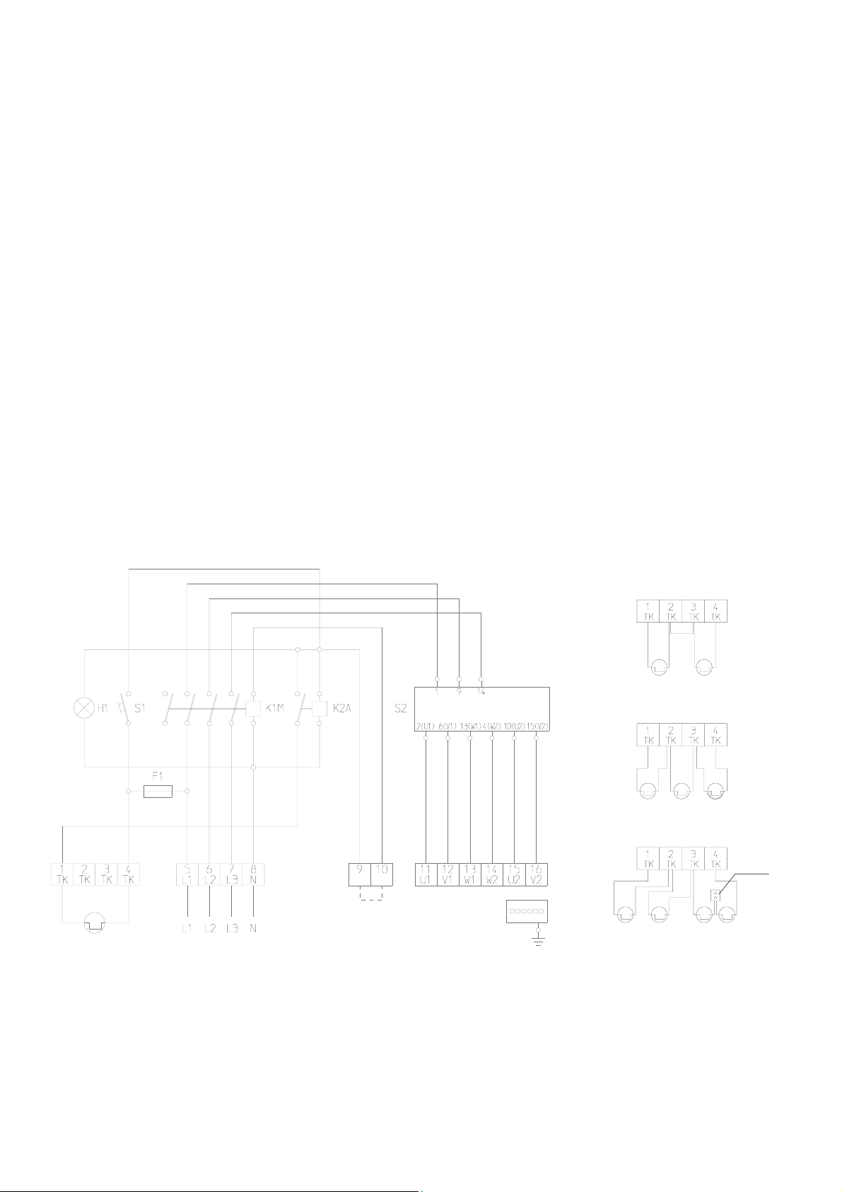
SW 2 380 DI switching unit
Design
◊ Rotary current 400 Volt, fan 2-speed, maximum
electrical capacity 4 kW
◊ On-plaster mount
◊ Full motor protection through integrated connections
for thermal contacts
◊ Plastic housing, protection type IP 65, protective in-
sulation in accordance with VDE
◊ Front plate with symbols for switching positions
◊ Power input and protective conductor terminals,
main contactor
◊ Control fuse, control switch with the functions “Off/
Speed 1/Speed 2”
◊ Operating light (goes out when there is a fan mal-
function and/or power interruption to the switching
unit)
◊ Reset button, motor output terminals, connection ter-
minals for thermal contacts and room thermostat.
Wiring diagram
Group switching
The switching unit is suitable for group switching. Several motors wired the same way can be connected to
one switching unit.
The total capacity of the connected motors may not exceed the permissible switch capacity of the switching
unit. The thermal contacts of all motors are to be connected in a row.
See figure below.
Switching on again after a problem
◊ Each time the power supply is interrupted or the fan
malfunctions, the fan reset button has to be pressed
once.
Grounding and earthing or protective wiring and
fuse protection must be done by the customer in
*
accordance with the requirements of the VDE as
well as the responsible EVU.
Thermal contact
Power switch
Room thermostat
or bridge
Star Delta Switch
Fan motor
Thermal protection for
2 units
Thermal protection for
3 units
Thermal protection for
4 units
Connect additional thermal
contacts in a row
Luster–
terminal
Legend
S1 Fan reset button K2A Auxiliary relay F1 Control fuse
S2 Control switch K1M Contactor to fan motor H1 Operating light
We reserve the right to make changes to dimensions and design in the interest of technical progress.
10


REMKO GmbH & Co. KG
Klima- und Wärmetechnik
32791 Lage, Im Seelenkamp 12
32777 Lage, PO Box 1827
Phone +49 5232 606-0
Fax +49 5232 606-260
E-mail info@remko.de
Internet www.remko.de
 Loading...