


REMKO PWW
Warm water heaters
Operation · Technology · Spare Parts
Edition GB - T08


3
Contents
Safety information
Unit description
Unit installation
Mounting examples
Electrical connection
Heating medium connection
Commissioning
Switching off
Care and maintenance
Repair
Air outlet accessories
Air inlet accessories
Accessory installation
4
4
5
6
7
8
9
9
10
10
11
12
14
Control units
Exploded drawing
Spare parts list
Intended use
Customer service and warranty
Environmental protection and recycling
Ratings tables/Characteristics
Calculation examples
Planning/Calculation/Units
Unit dimensions
Technical data
16
20
20
21
21
21
22
30
32
34
35
Made by REMKO
These operating instructions must be read thoroughly
before commissioning/using the unit!
These instructions are part of the unit and must always
be kept near to the site of installation or the unit.
Subject to changes; errors and typographical errors excepted!

4
REMKO PWW
Safety information
The units were subjected to extensive material, functional and
quality inspections and tests prior
to delivery.
The units can however constitute
a hazard if used improperly by
untrained persons or not for the
intended purpose.
Always observe the following
safety information:
■ The locally applicable building
regulations must be observed.
■ The operator is responsible for
correct installation of the units,
correct electrical installation and
safe operation of the units.
■ The units must be installed
and operated in a manner that
excludes any risk to persons
through radiated heat.
■ The units must only be attached
to constructions or ceilings with
sufficient load bearing capacity.
■ Attachment must take place
using suitable anchors to be attached to the unit.
■ Only trained specialists may
install and connect the heating
medium, establish electrical connections and carry out maintenance.
■ The units must not be installed
and operated in locations
where there is a risk of fire and
explosion.
■ The units must only be operated
in a completely installed
condition.
■ Safety components, e.g. protec-
tion grilles must not be removed
or rendered inoperational.
■ The units must only be operated
within the specified capacity
limits and with the approved
operating media.
Observe rating plate!
■ The air intake grilles must
always be kept free of dirt and
loose objects and the air outlet
must not be closed.
■ Never insert foreign objects into
the unit.
■ The units must not be sprayed
with a direct jet of water.
■ Never allow water to enter the
unit.
■ All electrical cables of the units
must be protected against damage, e.g. animals, etc.
NOTE
Perfect functioning of the units
is only ensured when the flow
temperature at the unit inlet
and the pump capacity correspond to the selected unit
classification.
Unit description
These units are stationary, indirectly fed air heaters with copper/
aluminium fin heat exchanger for
connection to a pumped hot water
system up to max. 130°C.
The units are suitable for wall or
ceiling mounting.
The units can be provided with
diverse air inlet and air outlet
accessories.
The units are provided with horizontal, individually adjustable air
outlet fins as standard.
The units are provided with a lownoise, aerodynamically designed,
sickle-shaped high-power axial
fan, individually adjustable air outlet fins and electrical terminal box.
The units are fitted with a
400V/50Hz, two-speed externalrotor motor as standard.
The units comply with the basic
health and safety requirements of
the pertinent EU regulations and
are easy to operate.
■ The units must be installed
outside traffic zones, e.g. also
the operating areas of cranes. A
protection zone of 1 m distance
must be kept free.
5
Unit installation
The following information must be
observed for safe unit installation.
■ The units must be arranged so
that accessed areas and workplaces are not located in the
direct air stream.
■ The units must only be mount-
ed on ceilings or roof constructions with sufficient load bearing capacity.
■ The heat exchangers must be
connected so that no vibrations
can be transferred from the unit
to the pipe system or vice versa.
■ For wall mounting, a minimum
height of 2.5 m to the bottom
edge of the unit must be
maintained.
■ For wall mounting above 4 m,
suction of the recirculated air
should take place from the
ground to ensure uniform
heating.
■ For ceiling mounting below
4 m, the units should be fitted
with an air outlet hood HG 4.
■ For ceiling mounting above
4 m, the units should be fitted
with the ceiling air outlet nozzle
AD.
■ Before connecting the units
to an existing water heating
system, the boiler and pump
must be checked for sufficient
capacity.
■ For maintenance and repair
purposes, a repair switch should
be mounted near to the unit.
■ The gap between the fan
impeller and housing must be
checked for the same distance.
■ Units with fresh air inlet
must be fitted with anti-frost
protection.
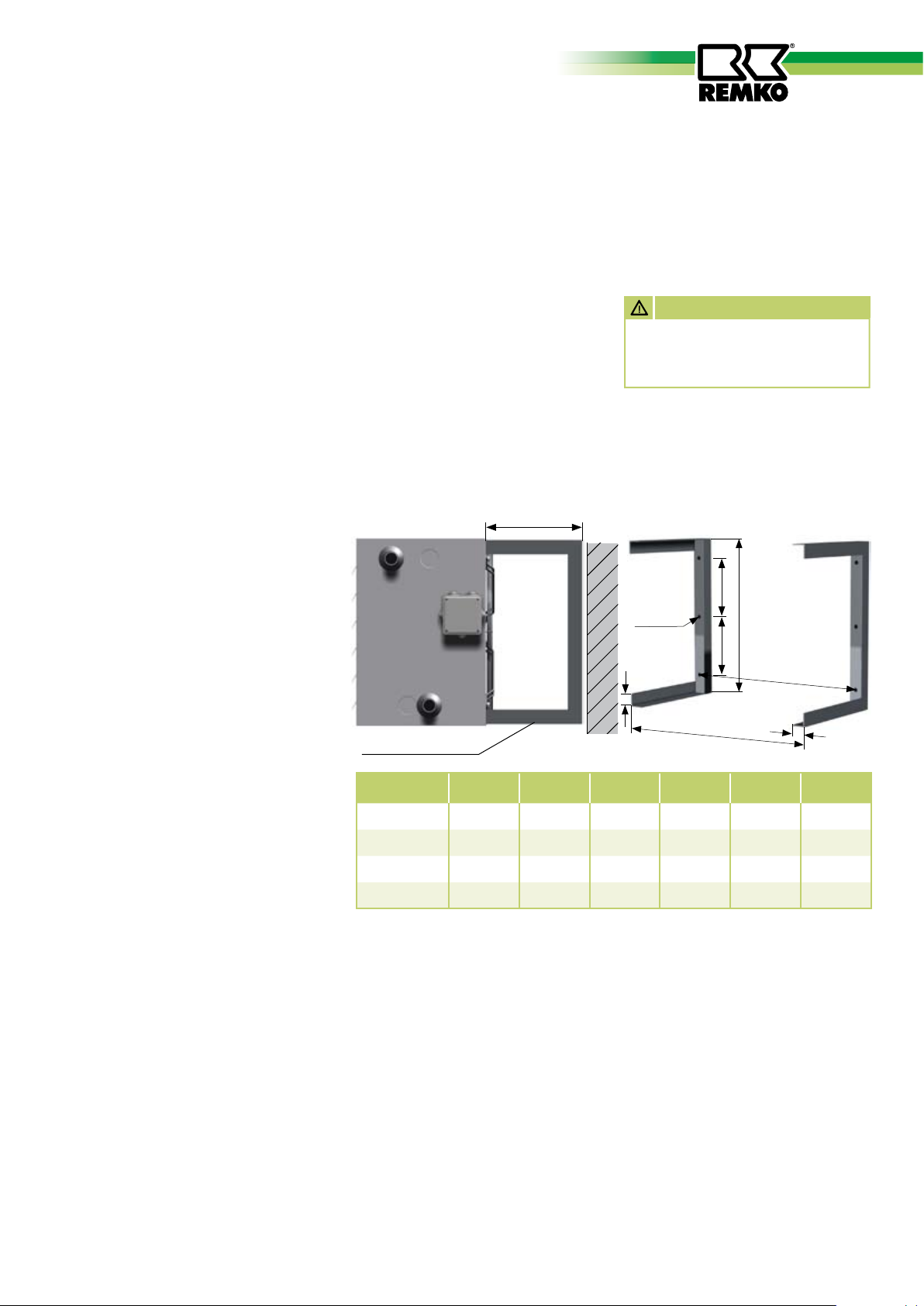
Brackets
Brackets (KO) for wall and ceiling mounting (2 per unit) must be inserted
into the recesses in the rear wall of the unit and attached to the unit using the enclosed screws.
Direct mounting parts such as
mixed-air or filter box must be
attached using a wall fastening
bracket (WFM).
When using local bracket construc-
ATTENTION
The brackets must be screwed
to the de-energised unit and
wall or ceiling.
tions, the minimum wall distance
“e” must be maintained!
Bracket KO
for wall and ceiling mounting
e
d
b
d
c
a
e
in mm
f
f
in mm
KO (L
PWW
40 x 40 x 3)
30
50
80
100
ø 12.5
f
a
in mm
b
in mm
c
in mm
d
in mm
552 432 506 155 270 40
632 507 586 192 270 40
792 622 746 250 270 40
872 732 826 305 340 40
Heat exchanger
copper/aluminium
The fin heat exchangers consist
of copper pipes with pressed on
pipe adapters.
■ The water inlet (flow) is
generally the bottom.
aluminium fins.
The fin assembly is enclosed by a
galvanised steel frame.
Collector, distributor and heating
medium connections are made of
■ The maximum operating tem-
perature is 130°C.
■ The maximum operating pres-
sure is 16 bar.
steel.
■ The heat exchangers are not
■ Heating medium connections
are established via threaded
suitable for operation with
steam or thermal oil.

6
REMKO PWW
Mounting examples
Circulation/fresh air operation
via the roof.
ALH
Circulation/fresh air operation
via the outside wall.
PWW
FK
SG
KA
MLK
4
KA
RK
ß
ß
KA
PWW
AG
1
2
WFM
ß
ß
FK
SG
KA
4
4
SG
2
MLK
WFM
UA
ß
ß
Wall opening appropriate to air
1
inlet grille size.
The mixed-air box must be fas-
2
tened using the wall bracket WFM
to a load bearing outside wall.
UA
3
3
ß
ß
The air intake channel and
3
air inlet piece must be fastened
to the outside wall locally.
The vertical part of this system
4
arrangement must be attached to the
wall using brackets so that the flexible
pipes are not subjected to weight.

7
U1
V1 W1 W2U2V2 11 12
TK TK
Electrical connection
Ceiling mounting
In circulation operation with
bracket KC
KO
PWW
Wall mounting
In circulation operation with filter
FK, mixed-air box MLK, bracket
WFM and injection shutter.
MLK
FK
PWW
IJ
WFM
Legend:
AG = Fresh air inlet grille
ALH = Fresh air inlet hood
FK = Filter box
KA = Warmth channel interim
piece
KO = Brackets
MLK = Mixed-air box
Electrical connections of the unit
must only be established by authorised specialists in compliance
with the applicable regulations of
the local electricity supply company as well as the VDE installation
requirements relating to the unit.
ATTENTION
Failure to observe the pertinent
requirements, operating instructions and electrical wiring diagrams relating to the unit can
give rise to malfunctions with
consequential damage.
This will invalidate the
warranty!
Unit connection
The units are fitted with twospeed, 400V three-phase axial fans
as standard.
With the appropriate control units
(accessory), speed selection takes
place via Y/D switching.
Motor protection is provided
via built-in thermal contacts
that drop out at a fan motor
winding temperature of 130°C in
conjunction with a suitable control
unit (accessory).
Connection of the three-phase
motors to the respective control
units takes place via the associated
electrical wiring diagrams.
ATTENTION
When the fan is stationary, the
heating medium supply must
be simultaneously interrupted.
Connection of several units
If necessary, several units (also different sizes) can be operated parallel via a control unit (accessory).
The total capacity of the connected units must not exceed the
maximum switching capacity of
the respective control unit.
For thermal motor protection, the
thermal contacts of all motors
must be connected in series. See
separate wiring diagrams.
Only one external control device
(thermostat, day/night control,
etc.) can be connected per control
unit.
Terminal box on unit
Fuse protection in the supply
to the control unit must be in
compliance with the applicable
regulations.
The connections in the terminal
box must be connected to the
respective control unit (accessory).
ATTENTION
Only trained specialists may
establish electrical connections.
RK = Rain collar
SG = Flexible pipe
WFM= Wall bracket
IJ = Injection shutter
8
REMKO PWW
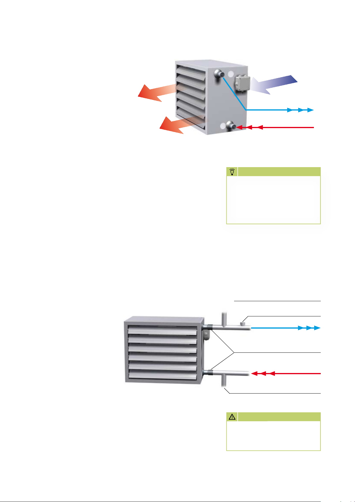
Heating medium connection
Connection to water
heating system
Prior to connection to the heating
system on-site, it must be ensured that the respective capacity
requirements of the unit can be
made available at all times.
■
Connection of the unit on the
water side must take place onsite via suitable pipe fittings and
shut-off valves in the flow and
return.
The use of compensators and
automatic deculators is recommended!
■
T he water inlet (flow) is gener-
ally at the “top“.
Air outlet
■
The fin heat exchangers must
be thoroughly vented after
installation.
Air cushions in the heat
exchanger will reduce the
heating capacity!
■
The fin heat exchangers operate
in counterflow.
Air inlet
Water outlet
Water inlet
■
See technical data for pipe con-
nection thread sizes.
NOTE
When tightening the screwed
connections of the heating
medium connection, a suitable
tool must be used to prevent
the connecting pipes rotating
in order to avoid damage.
■
The connection side can be
either on right or left.
Draining if there is a risk of
frost
It is not possible to statically drain
the fin heat exchanger completely.
The fin heat exchanger can only be
drained completely using compressed air.
Important information
on frost protection!
To prevent frost damage, anti-frost
protection must be provided at
temperatures below 0°C.
Where systems in rooms at risk
from frost are not used for extended periods, under no circumstances must water be present in
the heat exchanger.
If this is not possible, a suitable
antifreeze agent must be added to
the heating medium (water).
Venting
❄
ATTENTION
Frost damage to the fin heat
exchanger does not fall under
the warranty!
Anti-frost thermostat
Water outlet
Pipe fitting
Water inlet
Draining

9
Commissioning Switching off
Prior to initial use
ATTENTION
Commissioning can only
take place when it is ensured
that mounting and electrical
installation has been carried
out in compliance with the
pertinent requirements of the
EC Directives.
1. Correct mechanical installation
must be verified.
2. Correct connection to the
heating system on-site must be
verified.
3. It must be ensured that hot
surfaces are protected against
accidental contact.
4. It must be verified that the
electrical wiring of the units has
been carried out in compliance
with the applicable directives
and standards using the supplied wiring diagrams.
9. It must be ensured that the fan
rotates in the direction of the
arrow.
The direction of rotation can
be changed by interchanging
two phases.
10. It should be noted that when
using a speed control (accessory) the power of the control
unit must correspond to the
power of the motor.
During initial
commissioning
During initial commissioning, all
regulating, control and safety
devices must be checked for their
proper functioning and correct
adjustment.
1. The power consumption of the
fan must be measured.
The nominal current must not
exceed the values on the rating
plate at the respective operating speeds.
Set the switch of the respective
control unit to the “Off” or “0”
position.
For extended periods of nonuse:
■
Disconnect the electrical con-
nection in all poles.
■
Shut-off the heating medium
connection.
■
Where there is s risk of frost,
the entire system must be
drained if no suitable antifreeze
agent has been added.
NOTE
The heat exchanger can only
be drained completely using
compressed air.
5. The fan space as well as the
inlet and outlet area must be
checked for the presence of
foreign bodies.
6. It must be ensured that all air
outlets are open.
7. The fan must be checked for
smooth operation.
8. Switch on the power to the control unit (accessory) and switch
on the unit via the control
switch of the control.
2. Check the control/regulating
function of the fan.
3. Check the motor protection
function of the fan.
4. If fitted, check the function of
the frost protection and room
thermostats.
5. Check the complete system for
de-energised installation and
possible vibrations.
6. Check the heating medium supply pipes for correct connection
and tightness.
NOTE
After disconnecting the control
unit from the power supply, in
the event of a power failure or
shutdown on faults, the control switch must always first be
switched to back to the “0”
position.

10
REMKO PWW
Care and maintenance
The units are virtually maintenance-free in normal operation.
However, to ensure trouble-free
operation, they should be inspected regularly and cleaned if
necessary.
Important precautions to be
taken before carrying out any
maintenance:
■
The units must be disconnected
from the supply in all poles and
locked to prevent unauthorised
reconnection.
ATTENTION
It does not suffice to switch off
the unit only via the switch!
■
Wait for the fan to stop.
■
Shut-off the water circuit and
lock to prevent unauthorised
opening.
■
Allow the fin heat exchanger to
cool down.
NOTE
The fan impeller and aluminium fins must not be damaged
or bent.
Cleaning agents
■
The units must be cleaned only
dry or with a moist cloth and a
small amount of soap solution if
necessary.
■
Under no circumstances use
high-pressure cleaners or steam
jet equipment.
■
Do not use caustic or solvent-
containing cleaning agents.
Cleaning the units
■
Clean all air inlets and air outlet
fins.
■
Clean the fan impeller. If ne-
cessary, remove the motor or
protection grille.
■
Clean the heat exchanger fins
either by blowing out, suction
or with a soft brush.
■
Remove heavy fouling on the
fan and aluminium fins with a
soap solution.
Repair
Fan replacement
1. Disconnect the electrical connection of the motor.
2. Remove the protection grille
with fan from the housing.
3. Remove the protection grille
from the fan motor.
4. Carefully refit the new fan in
reverse order.
5. Check the fan impeller for
smooth operation and freedom
of movement with respect to
the fan housing.
6. Re-establish the electrical connection of the motor correctly.
Replacement of
fin heat exchanger
1. Disconnect the electrical con-
nection of the unit.
2. Shut-off the water-sided unit
connection.
3. Drain the fin heat exchanger
completely and disconnect the
heating medium connections.
4. Remove any fitted air inlet and
air outlet accessories and remove the unit from the bracket
(support).
5. Remove the rear wall (support
plate) together with the fan.
6. Loosen the fin heat exchanger
fastening screws and remove
the heat exchanger towards the
air inlet side.
7. Fit the new heat exchanger and
reassemble the unit in reverse
order including accessories.
8. Re-establish electrical connections.
Checks after repairs:
■
The fan impeller must rotate
freely in the fan housing
■
The distance between the fan
impeller and fan housing must
be the same
■
The fan motor must rotate in
the direction of the arrow and
connected in correct phase
■
All screw connections must be
checked for tightness
ATTENTION
After completing all work on
the units, an electrical safety
test must be carried out in
accordance with VDE 0701.
NOTE
■
Only suitable cleaning agents
must be used to remove heavy
fouling.
Repair and maintenance work
must only be carried out by
authorised specialists.
11
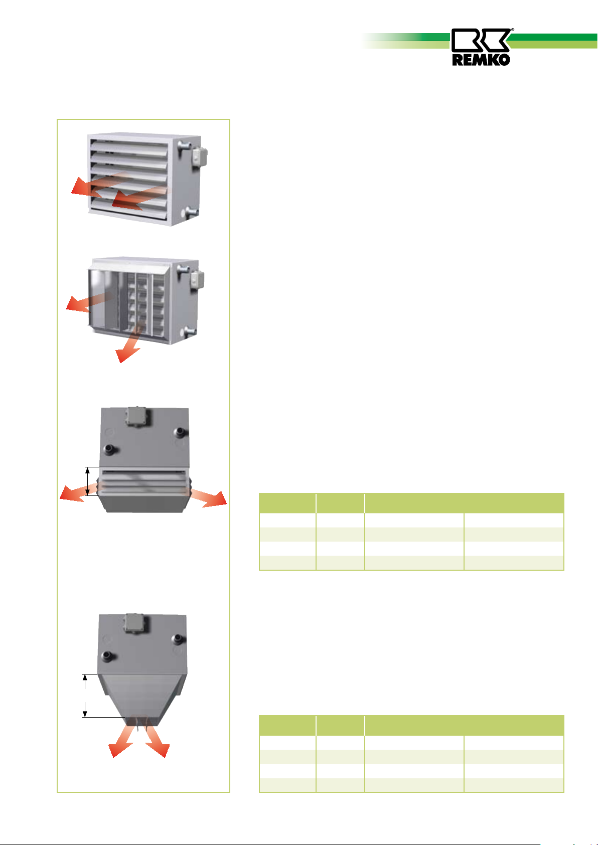
Air outlet accessories
Standard type
The units are provided with horizontal, individually
adjustable air outlet fins as standard.
■
The fins can easily be removed by unclipping.
Air outlet shutter B
Vertical, individually adjustable air outlet fins for
wall and ceiling use.
The air outlet shutter B is mounted directly in front of the horizontal air outlet fins.
Use of the shutter enables a high blowing range.
The unit depth increases by 115 mm in the case of all unit types.
■
Retrofitting is easily possible.
W
Air outlet hood HG 4
This air outlet hood serves uniform air distribution in four directions
at low mounting heights.
The air outlet hood is not suitable for mounting hoods above 4 m.
■
For retrofitting, the standard horizontal air outlet fins of the unit
c
W
must be removed.
PWW
30
50
80
100
c
in mm
166 6 m 1.- Setting 9 m 2.- Setting
166 8 m 1.- Setting 11 m 2.- Setting
166 10 m 1.- Setting 13 m 2.- Setting
236 12 m 1.- Setting 15 m 2.- Setting
Blowing range W in metres
Ceiling air outlet nozzle AD
The ceiling air outlet nozzle serves for concentrated control of the
hot air stream and must be used at mounting heights above 4 m in
high halls.
■
For retrofitting, the standard horizontal air outlet fins of the unit
c
must be removed.
PWW
30
50
W
W
80
100
We reserve the right to make changes to dimensions and design in the interest of technical advances.
c
in mm
200 5.0 m 1.- Setting 6.5 m 2.- Setting
230 5.5 m 1.- Setting 6.5 m 2.- Setting
270 5.5 m 1.- Setting 7.0 m 2.- Setting
290 7.0 m 1.- Setting 9.0 m 2.- Setting
Blowing range W in metres

12
REMKO PWW
Air inlet accessories
Fresh air inlet grille AG
Fresh air inlet grille for fresh air intake through the outside wall
PWW
30
b1
b
50
80
100
a
For wall opening: Dimension a and b + about 15 mm
a
in mm
518 598 398 478
598 678 483 563
758 838 588 668
838 918 698 778
a1
in mm
b
in mm
b1
in mm
a1
Wall bracket WFM
for fastening the unit with air inlet accessories (PWW+FK+MLK or
a
d
b
c
PWW+FK) to the outside wall.
PWW
30
50
80
100
a
in mm
1115 490 55 60
1165 590 55 60
1215 690 55 60
1295 690 55 60
b
in mm
c
in mm
d
in mm
Mixed-air box MLK
for circulation/fresh air/and mixed air operation. With two shutter
flaps working in opposite direction as standard, without servomotor (accessory). With the supplied variable cover, the air direction
b
a
c
can be freely selected.
PWW
30
50
80
100
in mm
560 440 300
640 515 350
800 630 400
880 740 450
a
b
in mm
c
in mm
Filter box FK
with pocket filter insert removable from the side
(filter class G3, depth 100 mm)
b
PWW
30
a
c
50
80
100
a
in mm
560 440 400
640 515 400
800 630 400
880 740 400
b
in mm
c
in mm
We reserve the right to make changes to dimensions and design in the interest of technical advances.

13
Air inlet accessories
Fresh air inlet hood ALH
for fresh air intake via roof.
e
d
b
a
15
c
PWW
30
50
d
80
100
a
in mm
b
in mm
c
in mm
d
in mm
in mm
520 240 260 20 215
600 310 290 20 215
760 360 290 20 215
840 410 400 20 325
e
Rain collar RK
with warmth channel interim piece in 1000 or 500 mm length
e
c
c1
PWW
30
50
d
b
a
d
d
80
100
Flexible pipe SG
a
in mmbin mmcin mmc1in mmdin mmein mm
520 240 1000 500 20 220
600 310 1000 500 20 220
760 360 1000 500 20 220
840 410 1000 500 20 220
Flexible conn. (vibration isolation) betw. unit and air channel system.
(Dimension(s) for mounting on warmth channel intermediate piece).
(e)
b
PWW
30
c
a
d
50
80
100
a
in mm
b
in mm
c
in mm
d
in mm
in mm
520 400 120 20 240
600 475 120 20 310
760 590 120 20 360
840 700 120 20 410
e
b
d
a
d
Warmth channel interim piece KA
Warmth channel interim piece in 1000 or 500 mm length
c1
d
PWW
c
30
50
80
100
a
in mm
520 240 1000 500 20
600 310 1000 500 20
760 360 1000 500 20
840 410 1000 500 20
b
in mm
c
in mm
Circulation suction adapter UA
a
d
c
We reserve the right to make changes to dimensions and design in the interest of technical advances.
b
With air inlet protection grille for mounting on a channel as
standard.
PWW
30
50
80
100
a
in mm
520 240 400 20
600 310 450 20
760 360 650 20
840 410 800 20
b
in mm
c
in mm
d
in mm
e
in mm
d
in mm

14
REMKO PWW
1
C
ϑ
2
Accessory installation
Mixed-air box MLK
The mixed-air box MLK is designed for both wall and ceiling
mounting.
The ratio of fresh air to recirculated
air can be continuously adjusted
manually or with a flap servomotor
(accessory).
With the supplied variable cover,
the direction of the air on the inlet
side can be freely selected.
For operation of the mixed-air box
with flap servomotor, the mixedair flaps must be checked regularly
for easy movement and fouling.
Filter box FK
The filter box with pocket filter is
designed for direct mounting on
the units.
The pocket filter can be removed
from the side.
The filter medium of the pocket
filter can be regenerated and has
the filter class G3.
Further filter classes are available
on request.
Filter maintenance
Depending on the operating conditions, the pocket filter must be
checked regularly and cleaned or
replaced if necessary.
Automatic monitoring
The degree of clogging of the
pocket filter can be monitored
via a differential pressure switch
(special accessory).
Anti-frost thermostat FS
The anti-frost thermostat is a
precise water temperature sensor,
which can be subsequently mounted on the surface of pipes.
The thermostat is fitted with a
precision sensitive switch.
The supplied strap with clamp
enables easy subsequent fitting
without draining the heating system.
Installation
Prior to fitting, the pipe insulation
in the contact area of the sensor
must be removed.
The parts required for fitting, e.g.
strap or clamp, etc., are supplied
with the unit.
Wiring diagram
Mounting clips
Installation
Fastening of the mixed-air and
filter box takes place with the supplied mounting clips (4 pieces).
When the final pressure difference
is reached, the filters must be
replaced with filters with the same
quality class.
Spare pocket filter EF:
PWW 30 EDP No. 385405
PWW 50 EDP No. 385406
PWW 80 EDP No. 385407
PWW 100 EDP No. 385408
Contact 1
opens with a rise of temperature.
Contact 2
closes with a rise of temperature.
Technical data:
Setting range 25 to 95°C
Switching difference adjustable.
Maximum ambient temperature
70°C.
NOTE
In order to ensure perfect functioning of the freeze protection
control, the sensor must always be mounted at the water
outlet (return).
15
Typ KSH
N L1
230V/1~
1 2 3
Aderbezeichnung
Stellungsgeber 0-10V
Aderbezeichnung
1 2
3
5
N L1
y
N L1
230V/1~
1 2
3
U
vcc
4
Typ KSP
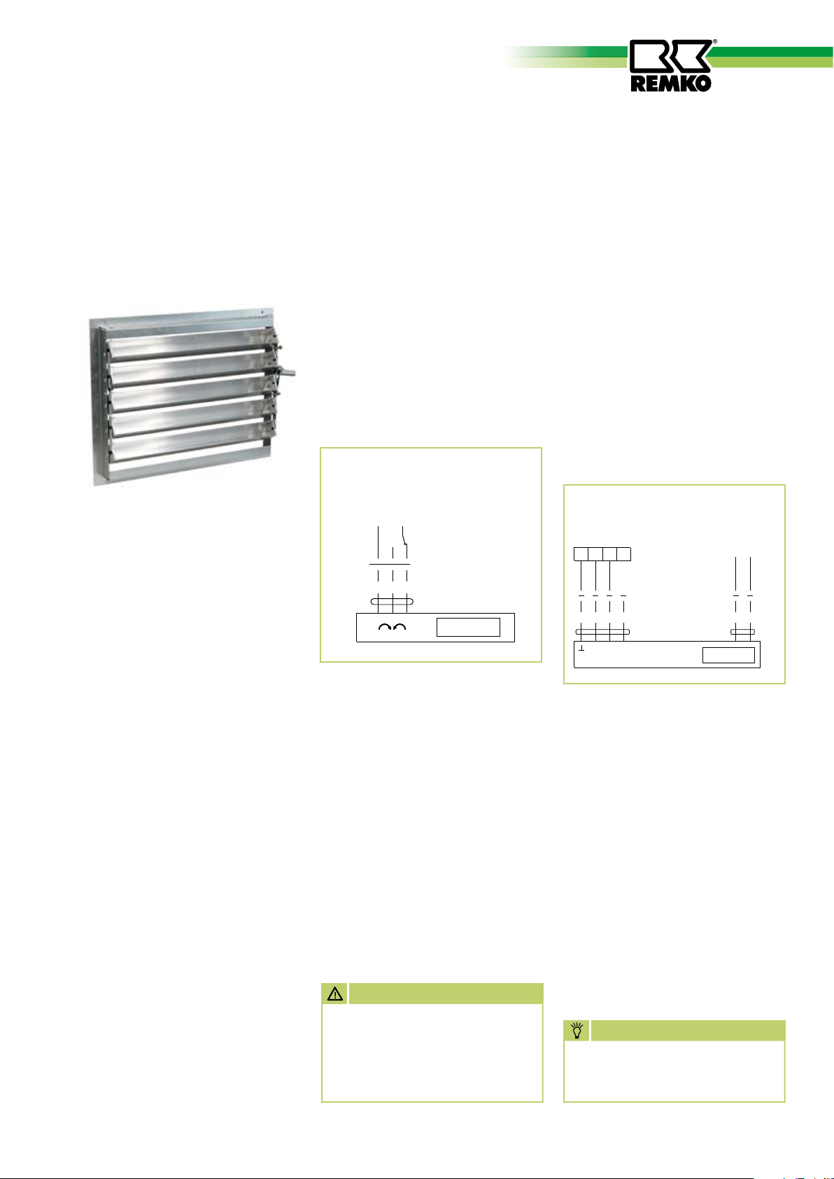
Injection shutter IJ
The injection shutter is a useful extension for the REMKO PWW unit
and is designed for direct mounting on the units.
The supply air is optimally blown in
via the injection shutter. The position of the air directing fins influences the air velocity and air outlet
temperature of the total air flow.
This technology provides for a higher blowing range and more rapid
heating of the rooms.
Intake of the already heated room
air prevents the occurrence of
varying air temperatures. The heat
is distributed evenly throughout
the room.
Installation
Unclip the existing fins and fix the
injection shutter with four screws.
The position of the fins can also be
electrically regulated via an optional control.
Servomotor KSH
(open/closed)
The servomotor is mounted directly on the flap shaft. It is provided
with a universal terminal block and
is fixed with the supplied locking
element.
The drive is overload-proof and
requires no limit switch.
For manual actuation, the gear can
be disengaged with a self-resetting
pushbutton.
Wiring diagram
Technical data:
Servomotor Type KSH
overload-proof
Rating 2.5 W, 230V, 50Hz
Degree of protection IP 54
Operating time about 150 seconds
Maximum ambient temperature
50°C.
Servomotor KSP
(variable speed)
The servomotor type KSP is supplied with 230V.
A transformer converts the system
voltage into a low voltage of 24V.
The motor is controlled depending
on the input voltage and position
of the feedback potentiometer.
The direction of rotation of the
motor can be reversed with the
rotary control switch.
The connection of an electrical
indicator for the flap position and
further servomotors is possible.
Wiring diagram
Technical data:
Servomotor type KSP
overload-proof
Rating 3.5 W, 230V, 50Hz
Degree of protection IP 54
Operating time about 150 seconds
Maximum ambient temperature
50°C.
ATTENTION
Installation and repairs to the
electrical installation must
only be carried out by authorised electrical specialists for
safety reasons.
NOTE
All electrical wiring terminals
must be checked for tightness
and retightened if necessary.

16
REMKO PWW
Switchgear SW 2 - 380 DI
Three-phase 400V,
two-speed fan
maximum switching capacity
4 kW, surface mounting, motor
protection by means of built-in
thermal contacts in fan motor.
Design
Sturdy plastic housing,
Degree of protection IP 54.
Totally-insulated according to VDE.
Front plate with symbols for switch
positions, supply and protective
conductor terminals, main contactor, control switch with the
functions “Off/Setting 1/Setting
2“, control fuse, indicator light
(extinguishes on fan faults and/or
interruption of power supply to
control unit), fault reset button,
terminals for motor output, terminals for thermal contacts and room
thermostat.
Reconnection after a fault
After each main break or fan fault,
the “Fan fault reset button“ must
be pressed once!
Multiple series connection
The control unit is suitable for
multiple series connection. Several
motors in the same circuit can be
connected to a control unit
The total rating of the connected
motors must not exceed the permissible switching capacity of the
control unit.
The thermal contacts of all motors
must be connected in series.
Note on safe operation
Earthing, multiple earthing or
protection switching and mains
protection must be carried
out on-site according to VDE
specifications and the regulations
of the responsible electricity supply
company. Only specialists may
establish electrical connections
based on the wiring diagrams in
compliance with the applicable
regulations, taking into account
local regulations.
Circuit and wiring diagram
S1 = Fan fault reset button
K2A = Auxiliary relay
We reserve the right to make changes to dimensions and design in the interest of technical advances.
F1 = Control fuse
S2 = Control switch
K1M = Contactor for fan motor
H1 = Indicator light

17
Control unit MSRD 2.5
0
D
U
1 2 3
4
7 8 9
10
11
12
13
14
15
16
17
18
5
6
S1
R1
K1
13
14
K1
F1
6,3 A
H1
X1
X2
K1
A1
A2
PE L1 L2 L3 N
PE U1 V1 W1 U2 V2 W2 TK TK
15
RT RT
16
4
4
4
11
1
3
5
13
2
4
6
14
Raumthermostat
Thermokontakte
im Motor
Einspeisung 400 V / 50 Hz
Erdung nach örtlichen Vorschriften
Motor 3~
Thermoschutz
für 2 Geräte
Thermoschutz
für 3 Geräte
Thermoschutz
für 4 Geräte
weitere Thermokontakte
in Reihe schalte n
13TK14
TK
13TK14
TK
13TK14
TK
6 7 8 9 10 11 12 14
13
1 2 3 4 5
1 3 5
2 4 6
Three-phase 400V,
two-speed fan
maximum switching capacity 2.5
kW, surface mounting, motor
protection by means of built-in
thermal contacts in fan motor.
Design
Sturdy plastic housing,
Degree of protection IP 41.
Totally-insulated according to VDE.
Front plate with symbols for switch
positions, supply and protective
conductor terminals, main contactor, control switch with the
functions “Off/Setting 1/Setting
2”, control fuse, indicator light
(extinguishes on fan faults and/or
interruption of power supply to
control unit), fault reset button,
terminals for motor output, terminals for thermal contacts and room
thermostat.
Reconnection after a fault
In the event of a fault, the unit
switches off and does not switch on
again automatically. After clearing
the fault, the unit can be switched
on again by setting the control
switch to “0” and waiting for
about30 seconds.
Multiple series connection
The control unit is suitable for
multiple series connection. Several
motors in the same circuit can be
connected to a control unit.
The total rating of the connected
motors must not exceed the permissible switching capacity of the
control unit.
The thermal contacts of all motors
must be connected in series.
Note on safe operation
Earthing, multiple earthing or
protection switching and mains
protection must be carried
out on-site according to VDE
specifications and the regulations
of the responsible electricity supply
company. Only specialists may
establish electrical connections
based on the wiring diagrams in
compliance with the applicable
regulations, taking into account
local regulations.
Circuit and wiring diagram
S1 = Control switch K1 = Contactor R1 = PTC element
F1 = Control fuse H1 = Indicator light
We reserve the right to make changes to dimensions and design in the interest of technical advances.

18
REMKO PWW
PE L1 L2 L3 N PE U1 V1 W1U2 V2 W2X1 1 2 3 4 5 6 7 8 9 10 11 12X2 13 14 15
TK FS TF
Mischluft-
klappe
Potenzialfreier
Kontakt TK
Potenzialfreier
Kontakt FS
Potentiometer
zum Abgleich des
Temperaturfühlers
Spannungsversorgung Ventilatoranschluß
Control unit MAK-2
Three-phase 400V,
two-speed fan
maximum switching capacity 8 kW
Surface mounting, motor protection by means of built-in thermal
contacts in the fan motor, terminals for thermal contacts, room
thermostats, anti-frost thermostat
and mixed-air box servomotor.
Design
Sturdy plastic housing,
Degree of protection IP 54.
Totally-insulated according to VDE.
Fully electronic two-step control
unit with digital display.
Two modes are available, “Manual“ and “Automatic“.
Operation takes place via a large
sized membrane keyboard.
In the automatic mode, the fan
speeds are controlled according to
the freely programmable temperature difference.
Day/night/temperature control including week programme provided
as standard. Four switching times
are available for day and night
respectively.
Available for motor protection are
thermal contact terminals.
Terminals for anti-frost thermostat
and continuously variable flap servomotor are provided as standard.
Function
The mixed-air flaps can be continuously controlled via flap servomotor. When the unit is switched
off, the flaps assume a “CLOSED“
position.
The anti-frost thermostat also
closes the flaps and switches off
the fan.
Reconnection after a fault
After a power failure (up to
three hours) the unit restarts
automatically.
After operation of the thermal
contacts, the unit can be reset
after cooling down via the “OFF“
button.
The antifreeze sensor automatically
starts the unit in the previously
selected programme mode after a
rise of temperature.
Multiple series connection
The control unit is suitable for
multiple series connection. Several
motors in the same circuit can be
connected to a control unit.
The total capacity of the connected motors must not exceed
the permissible switching capacity
of the control unit.
The thermal contacts of all motors
must be connected in series.
Note on safe operation
Earthing, multiple earthing or protection switching and mains protection must be carried out on-site
according to VDE specifications
and the regulations of the responsible electricity supply company.
Only specialists may establish
electrical connections based on the
wiring diagrams in compliance with
the applicable regulations, taking
into account local regulations.
Wiring diagram
We reserve the right to make changes to dimensions and design in the interest of technical advances.

19
Control unit, 5-stage
EG
TK
TK W2 U2 V2
W1V1U1
J
N
L1 L2
L3 U1
V1 W1
TK TKRT RT
N L1 L2 L3PE
J
FS FS
12
11 14
N L L
Raum-
thermostat
Frostschutz-
thermostat
250VAC
max.2A
230VAC
max.1A
Eingangsspannung
400V / 3~N / 50 Hz
3~ Motor mit
Thermokontakten
Kontaktbelastung
Lüfter
Aus/Ein
hohe Drehzahl
∆ - Schaltung
niedere Drehzahl
Y - Schaltung
TK
W2 U2 V2
TK
U1
V1 W1
PE
L1 L2 L3
TK W2 U2 V2
TK
U1
V1 W1
PE
L1 L2 L3
Voltage Current
Degree of
protection
Weight
Control unit V A IP kg
3 EG
5 EG
400 3.0 54 11.1
400 5.2 54 15.6
Wiring diagram five-stage control unit 3 EG/5 EG
Five-stage control units,
400V/50Hz, three-phase with
indicator light.
Motor protection takes place
by the connection of thermal
contacts.
In the event of a fault, (operation of the thermal contacts), the
internal contactor drops out and
disconnects the motor from the
power supply.
After the motor has cooled down
and the fault cleared, the mode selector switch must first be switched
to the “0“ position and then back
to the required operating position
(speed position).
The control units have a connection for external control devices,
e.g. room thermostat, anti-frost
thermostat, servomotor, recirculating pump, indicator light, solenoid
valve, mixer, etc. (observe contact
rating).
Fan motor 400V, two-step
D / Y switching and thermal contacts
Standard units
Wiring diagram
We reserve the right to make changes to dimensions and design in the interest of technical advances.
ATTENTION
Electrical heater connection
must be carried out by authorised specialists as defined
in DIN EN 60335-1 and VDE
0116.
NOTE
All electrical wiring terminals
must be checked for tightness
and retightened if necessary.

20
REMKO PWW
Exploded drawing
4
5
6
1
1a
1b
2
We reserve the right to make changes to dimensions and design in the interest of technical advances.
Spare parts list
No. Designation
PWW 30
EDP No.
3
7
PWW 50
EDP No.
PWW 80
EDP No.
PWW 100
EDP No.
1 Heat exchanger Bg. 2 1105211 1105215 1105219 1105223
1a Heat exchanger Bg. 3 1105212 1105216 1105220 1105224
1b Heat exchanger Bg. 4 1105213 1105217 1105221 1105225
2 Electrical terminal box 1105268 1105268 1105268 1105268
3 Housing 1105274 1105275 1105276 1105277
4 Fan protection grille 1105207 1105208 1105209 1105210
5 Fan 400V/two-speed 1105242 1105243 1105244 1105245
6 Support plate 1105264 1105265 1105266 1105267
7 Air outlet fin 1105284 1105285 1105286 1105287
When ordering spare parts, also quote the serial number of the unit (see rating plate) in addition to the EDP number!

21
Intended use
Customer service and
warranty
Environmental
Protection and
Recycling
Owing to their design and equipment, the devices are intended
solely for heating and ventilation
purposes in industrial or commercial use (not for domestic heating).
The unit is designed for use with
air inlet and air outlet accessories
approved by the manufacturer.
The units must only be operated
by suitably trained personnel.
The manufacturer disclaims all
liability for any damage
attributed to failure to observe
relevant instructions, statutory requirements applicable at the place
of use or unauthorised changes to
the unit.
NOTE
A precondition for any warranty claims is that the dealer or his
customer has completed and
returned the enclosed “Warranty
document“ to REMKO GmbH &
Co. KG at the time of sale and
commissioning.
The units were repeatedly tested for perfect functioning at the
factory.
However, if faults should occur
which cannot be cleared by the
operator via troubleshooting
measures, your specialised dealer or contract partner should be
contacted.
NOTE
Disposal of packaging
Think of the environment when
disposing of the packaging
material.
Our appliances are carefully packed for transport and delivered in
sturdy cardboard packaging and
on a wooden pallet if necessary.
The packaging materials are environmentally-friendly and can be
recycled.
The reuse of packaging material
makes a valuable contribution to
the reduction of waste and the
preservation of raw materials.
Dispose of packaging materials at
the facilities provided.
Disposal of old unit
Our production is subject to constant quality controls.
Use for any other purpose
than that described in these
operating instructions is not
permitted.
Failure to observe this rule
will invalidate all liability and
warranty.
Adjustment and maintenance
must only be carried out by
authorised specialists.
Only high-quality materials are
used, the majority of which are
recyclable.
Make your contribution towards
environmental protection by disposing of your old appliance in an
environmentally friendly manner.
Only dispose of old appliances at
recycling sites or where suitable
facilities exist.

22
REMKO PWW
PWW 30 ratings tables • Technical data
Type
Design
Speed
Electrical connection
Frequency
Power input
Nominal current
Air capacity
Sound pressure level
Blow. range ceiling*max.
Blow. range wall max.
Heating medium conn.
Weight
Heating medium
50/40 °C
60/50 °C
70/50 °C
80/60 °C
90/70 °C
rpm
Volt
Hz
kW
A
m³/h
dB(A)
m
m
Inch
kg
tL1 °C
- 15
- 10
- 5
+ 5
+ 10
+ 15
+ 20
- 15
- 10
- 5
+ 5
+ 10
+ 15
+ 20
- 15
- 10
- 5
+ 5
+ 10
+ 15
+ 20
- 15
- 10
- 5
+ 5
+ 10
+ 15
+ 20
- 15
- 10
- 5
+ 5
+ 10
+ 15
+ 20
PWW 30-2
two-speed
1340 1040
3 x 400 3 x 400
50 50
0.13 0.10
0.26 0.16
2250 1850
52 46
7.5 6.0
17 14
R ¾“ R ¾“
24 24
kW tL2 °C kW tL2 °C
13.1 2 10.6 2
12.0 5 10.7 7
10.9 9 9.7 10
0
0
0
0
0
9.6 12 8.6 14
8.3 16 7.5 18
7.0 20 6.4 21
5.9 23 5.3 24
4.5 26 4.0 27
16.5 5 14.0 5
15.1 9 12.9 9
13.8 12 11.8 12
12.7 16 10.7 16
11.5 20 9.6 20
10.1 23 8.6 24
8.7 27 7.5 27
7.4 30 6.4 30
17.3 6 14.7 6
15.9 9 13.4 9
14.4 13 12.1 13
13.1 16 10.7 16
11.8 21 9.8 20
10.4 24 8.6 24
8.5 26 7.2 26
7.1 29 5.8 29
20.3 10 17.5 10
18.8 13 16.1 13
17.3 16 14.7 16
15.9 19 13.4 19
14.4 24 12.1 24
13.1 27 10.7 27
11.8 31 9.8 30
10.4 34 8.6 34
23.2 13 20.4 15
21.7 17 18.9 18
20.3 20 17.5 20
18.8 23 16.1 23
17.3 28 14.7 28
15.9 31 13.4 31
14.4 34 12.1 34
13.1 37 10.7 37
tL1 Air inlet temperature tL2 Air outlet temperature* with ceiling air outlet nozzle AD
PWW 30-3
two-speed
1340 1040
3 x 400 3 x 400
50 50
0.13 0.10
0.26 0.16
2050 1640
53 48
7.0 5.5
16 13
R 1“ R 1“
26 26
kW tL2 °C kW tL2 °C
16.7 9 15.2 12
15.4 12 13.8 14
14.0 15 12.3 17
12.2 17 11.0 20
11.0 22 9.4 23
9.0 24 7.8 25
7.6 27 6.6 28
5.8 29 5.1 30
20.6 13 18.1 16
19.2 16 16.6 18
17.7 19 15.2 21
16.2 22 13.7 23
14.8 26 12.3 28
12.9 29 11.0 30
11.6 32 9.4 32
9.5 34 7.8 34
22.1 15 18.1 16
20.3 17 16.6 18
18.4 20 15.2 21
16.7 22 13.7 23
15.1 27 12.3 28
13.3 29 10.8 30
11.0 31 9.3 32
9.0 33 7.6 34
25.7 19 21.0 21
23.9 22 19.5 23
22.1 25 18.1 26
20.3 27 16.6 28
18.4 32 15.2 33
16.7 34 13.7 35
15.1 37 12.3 38
13.3 39 10.8 40
29.4 24 23.9 25
27.6 27 22.4 28
25.7 29 21.0 31
23.9 32 19.5 33
22.1 37 18.1 38
20.3 39 16.6 41
18.4 42 15.2 43
16.7 44 13.7 45
PWW 30-4
two-speed
1340 1040
3 x 400 3 x 400
50 50
0.13 0.10
0.26 0.16
1850 1500
55 49
6.5 5.0
15 12
R 1 ¼“ R 1 ¼“
27 27
kW tL2 °C kW tL2 °C
21.0 18 19.1 22
19.4 20 17.4 24
17.6 23 15.4 25
15.5 24 13.8 27
13.0 28 11.8 30
11.3 29 10.0 31
9.5 31 8.2 32
7.3 32 6.4 33
26.1 23 21.7 24
24.2 25 20.4 27
22.2 27 19.0 29
20.5 30 17.4 31
18.5 34 15.4 35
16.3 36 13.7 37
14.0 37 11.8 38
12.0 39 10.0 40
26.4 23 23.5 28
24.5 26 21.4 29
22.9 28 19.4 30
21.1 31 17.4 31
19.0 35 15.8 36
16.7 36 13.6 37
13.8 37 11.7 38
11.5 38 9.3 38
29.9 28 27.5 35
28.2 31 25.5 36
26.4 33 23.5 38
24.5 36 21.4 39
22.9 41 19.4 43
21.1 43 17.4 44
19.0 45 15.8 46
16.7 46 13.6 47
33.6 36 28.9 41
31.3 38 27.2 42
30.2 41 25.7 44
27.8 42 24.1 46
26.6 49 22.7 52
24.5 50 21.4 55
22.7 52 19.5 56
20.9 54 18.0 56
We reserve the right to make changes to dimensions and design in the interest of technical advances.

23
Characteristics • Heating medium resistances
Pressure difference values D of
accessories:
1. Accessories mounted on suction side
Component Type D
Mixed-air box MLK 5
Filter box (filter clean) FK 2
moderate filter clogging FK 7
Warmth channel interim piece
(per m)
Fresh air inlet grille AG 4
Circulation suction adapter UA 1
Fresh air inlet hood ALH 3
2. Accessories mounted on pressure side
Component Type D
Air outlet shutter B 4
KA 1
Air outlet hood HG 3
Ceiling air outlet nozzle AD 10
We reserve the right to make changes to dimensions and design in the interest of technical advances.

24
REMKO PWW
PWW 50 ratings tables • Technical data
Type
Design
Speed
Electrical connection
Frequency
Power input
Nominal current
Air capacity
Sound pressure level
Blow. range ceiling*max.
Blow. range wall max.
Heating medium conn.
Weight
Heating medium
50/40 °C
60/50 °C
70/50 °C
80/60 °C
90/70 °C
rpm
Volt
Hz
kW
A
m³/h
dB(A)
m
m
Inch
kg
tL1 °C
- 15
- 10
- 5
+ 5
+ 10
+ 15
+ 20
- 15
- 10
- 5
+ 5
+ 10
+ 15
+ 20
- 15
- 10
- 5
+ 5
+ 10
+ 15
+ 20
- 15
- 10
- 5
+ 5
+ 10
+ 15
+ 20
- 15
- 10
- 5
+ 5
+ 10
+ 15
+ 20
PWW 50-2
two-speed
1360 1020
3 x 400 3 x 400
50 50
0.26 0.18
0.52 0.29
3800 3180
55 50
8.0 7.0
22 18
R ¾“ R ¾“
31 31
kW tL2 °C kW tL2 °C
21.2 1 19.3 3
20.4 6 17.4 6
16.9 8 15.5 9
0
0
0
0
0
15.1 12 13.7 12
13.0 16 11.7 17
11.0 19 9.7 20
9.0 22 7.7 23
7.0 26 5.9 26
26.5 4 23.1 5
24.5 8 21.3 9
22.4 11 19.3 12
20.3 15 17.4 15
17.9 19 15.5 20
15.9 22 13.6 23
13.7 26 11.7 26
11.6 29 9.6 29
26.6 4 22.9 5
24.5 8 21.0 8
22.3 11 19.0 12
20.1 15 16.9 15
18.1 19 14.8 19
15.6 22 12.9 22
13.4 26 11.1 26
11.2 29 9.3 29
30.7 7 26.8 8
27.7 11 24.9 12
26.6 14 22.9 15
24.5 18 21.0 18
22.3 23 19.0 23
20.1 26 16.9 26
18.1 29 14.8 29
15.6 32 12.9 32
34.9 10 30.7 12
32.7 14 28.4 15
30.7 17 26.8 18
28.7 21 24.9 22
26.6 26 22.9 27
24.5 29 21.0 30
22.3 33 19.0 33
20.1 36 16.9 36
tL1 Air inlet temperature tL2 Air outlet temperature* with ceiling air outlet nozzle AD
PWW 50-3
two-speed
1360 1020
3 x 400 3 x 400
50 50
0.26 0.18
0.52 0.29
3400 2870
55 51
7.0 5.5
20 16.5
R 1“ R 1“
34 34
kW tL2 °C kW tL2 °C
27.3 8 24.7 10
24.9 11 22.2 12
22.3 14 19.8 15
19.7 17 17.4 18
17.1 21 14.8 21
14.4 23 12.5 24
11.8 26 10.1 26
9.2 29 7.7 28
34.8 13 29.4 13
32.1 16 27.1 16
28.8 18 24.7 19
26.2 21 22.2 21
23.5 26 19.8 26
20.7 28 17.4 28
18.1 31 14.8 30
15.3 33 12.5 33
34.9 13 29.4 13
32.2 16 26.8 16
29.4 19 24.3 18
26.5 21 21.8 21
23.8 26 19.4 25
20.9 28 16.6 27
17.3 30 14.5 30
13.8 32 11.9 32
40.1 17 34.2 18
37.6 20 31.8 21
34.9 23 29.4 23
32.2 26 26.8 26
29.4 31 24.3 30
26.5 33 21.8 33
23.8 36 19.4 35
20.9 38 16.6 37
45.1 21 38.8 22
42.3 24 35.9 24
40.1 27 34.2 28
37.6 30 31.8 31
34.9 36 29.4 36
32.2 38 26.8 38
29.4 41 24.3 40
26.5 43 21.8 43
PWW 50-4
two-speed
1360 1020
3 x 400 3 x 400
50 50
0.26 0.18
0.52 0.29
3150 2770
58 54
6.5 5.5
18 16
R 1 ¼“ R 1 ¼“
36 36
kW tL2 °C kW tL2 °C
36.1 18 32.8 19
32.8 20 29.3 21
29.5 22 26.1 22
25.9 24 23.0 24
22.6 27 19.6 27
19.0 29 16.6 29
15.6 31 13.5 30
12.0 32 10.1 31
45.9 24 38.8 24
42.3 26 35.8 26
38.1 28 32.7 27
34.6 30 29.3 29
31.1 34 26.0 33
27.3 36 22.9 35
23.8 37 19.5 36
20.1 39 16.5 38
46.1 25 38.8 24
42.6 27 35.3 25
38.8 28 32.2 27
34.9 30 28.8 29
31.4 34 25.7 33
27.6 36 21.9 34
22.8 36 19.0 36
18.2 37 15.8 37
52.9 31 45.1 30
49.7 33 42.1 32
46.1 35 38.8 34
42.6 37 35.3 35
38.8 41 32.2 40
34.9 43 28.8 41
31.4 44 25.7 43
27.6 46 21.9 44
54.0 31 48.5 33
50.8 34 44.9 35
48.1 36 42.8 37
45.1 39 39.8 39
41.9 44 36.8 45
38.6 46 33.5 46
35.3 48 30.4 48
31.8 50 27.8 51
We reserve the right to make changes to dimensions and design in the interest of technical advances.

25
Characteristics • Heating medium resistances
Pressure difference values D of
accessories:
1. Accessories mounted on suction side
Component Type D
Mixed-air box MLK 5
Filter box (filter clean) FK 2
moderate filter clogging FK 7
Warmth channel interim piece
(per m)
Fresh air inlet grille AG 5
Circulation suction adapter UA 2
Fresh air inlet hood ALH 4
2. Accessories mounted on pressure side
Component Type D
Air outlet shutter B 5
KA 1
Air outlet hood HG 4
Ceiling air outlet nozzle AD 10
We reserve the right to make changes to dimensions and design in the interest of technical advances.

26
REMKO PWW
PWW 80 ratings tables • Technical data
Type
Design
Speed rpm
Electrical connection
Frequency
Power input
Nominal current
Air capacity
Sound pressure level
Blow. range ceiling*max.
Blow. range wall max.
Heating medium conn.
Weight
Heating medium tL1 °C
50/40 °C
60/50 °C
70/50 °C
80/60 °C
90/70 °C
Volt
Hz
kW
A
m³/h
dB(A)
m
m
inch
kg
- 15
- 10
- 5
+ 5
+ 10
+ 15
+ 20
- 15
- 10
- 5
+ 5
+ 10
+ 15
+ 20
- 15
- 10
- 5
+ 5
+ 10
+ 15
+ 20
- 15
- 10
- 5
+ 5
+ 10
+ 15
+ 20
- 15
- 10
- 5
+ 5
+ 10
+ 15
+ 20
PWW 80-2
two-speed
880 670
3 x 400 3 x 400
50 50
0.42 0.28
0.76 0.46
5800 4400
55 49
8.5 6.5
25 19
R 1“ R 1“
44 44
kW tL2 °C kW tL2 °C
35.2 3 32.1 6
31.9 6 29.0 9
28.5 9 25.9 12
0
0
0
0
0
25.2 13 22.7 15
22.0 17 19.8 19
18.6 20 16.8 22
15.7 23 14.3 25
12.2 27 11.0 28
44.3 6 38.3 9
40.7 9 35.2 12
37.2 13 32.1 15
33.7 16 28.9 18
30.1 21 25.8 22
26.6 24 22.7 25
23.2 27 19.8 28
19.6 30 16.7 32
45.9 7 39.2 9
42.5 10 36.3 13
39.2 14 33.4 16
35.7 17 30.5 19
32.5 22 27.6 24
28.9 25 24.6 27
25.4 28 21.0 29
21.8 31 17.4 32
52.7 10 44.8 13
49.3 13 42.1 16
45.9 17 39.2 19
42.5 20 36.3 23
39.2 25 33.4 28
35.7 28 30.5 31
32.5 32 27.6 34
28.9 35 24.6 37
60.0 14 50.7 17
56.7 17 47.7 20
52.7 20 44.8 23
49.3 23 42.1 26
45.9 29 39.2 32
42.5 32 37.0 35
39.2 35 33.4 38
35.7 38 30.5 41
Air inlet temperature tL2 Air outlet temperature* with ceiling air outlet nozzle AD
t
L1
PWW 80-3
two-speed
880 670
3 x 400 3 x 400
50 50
0.42 0.28
0.76 0.46
5400 4300
55 49
8.0 6.0
23 18.5
R 1 ¼“ R 1 ¼“
47 47
kW tL2 °C kW tL2 °C
44.8 9 39.2 11
40.7 12 35.8 14
36.5 15 32.1 17
32.3 17 28.5 19
28.1 21 24.7 23
23.8 24 21.0 25
20.1 27 17.6 28
15.6 29 13.7 30
56.1 14 46.6 15
51.7 17 42.9 18
47.3 19 39.2 20
42.9 22 35.5 23
38.6 27 32.1 27
34.2 29 28.4 30
29.6 32 24.7 32
25.5 34 21.0 35
58.7 15 50.2 17
54.4 18 46.5 20
50.1 21 42.7 22
45.8 24 39.0 25
41.6 28 35.3 30
37.0 31 31.5 32
32.5 33 26.9 34
27.9 36 22.2 35
67.2 20 57.7 22
63.0 22 54.0 25
58.7 25 50.2 27
54.4 28 46.5 30
50.1 33 42.7 35
45.8 36 39.0 37
41.6 38 35.3 40
37.0 41 31.5 42
75.8 24 65.2 27
71.5 27 61.5 29
67.2 30 57.7 32
63.0 32 54.0 35
58.7 38 50.2 40
54.4 40 46.5 42
50.1 43 42.7 45
45.8 46 39.0 47
PWW 80-4
two-speed
880 6700
3 x 400 3 x 400
50 50
0.42 0.28
0.76 0.46
4730 3700
55 49
7.0 5.5
20.5 16
R 1 ¼“ R 1 ¼“
51 51
kW tL2 °C kW tL2 °C
58.0 21 49.1 24
52.6 22 44.4 37
47.1 24 39.7 47
41.7 26 35.1 37
36.3 29 30.6 40
30.8 30 26.0 39
26.0 32 22.2 40
20.1 33 17.1 40
72.7 27 58.4 28
67.0 29 53.7 30
61.2 31 49.0 31
55.5 32 44.3 33
49.8 36 39.6 37
44.0 38 34.9 38
38.3 39 30.5 40
32.6 41 25.9 41
74.2 28 63.1 32
68.7 30 58.4 33
63.2 32 53.7 35
57.7 34 49.0 36
52.3 38 44.2 41
46.6 39 39.5 42
40.9 41 33.9 42
35.3 42 28.4 43
85.2 35 72.5 39
79.7 36 67.8 40
74.2 38 63.1 42
68.7 40 58.4 43
63.2 45 53.7 48
57.7 46 49.0 50
52.3 48 44.2 51
46.6 49 39.5 52
91.0 38 77.6 43
85.8 40 73.2 44
80.6 42 68.7 46
75.6 44 64.3 48
70.4 48 59.5 51
65.3 50 55.3 53
60.1 52 50.8 54
55.0 54 46.4 56
We reserve the right to make changes to dimensions and design in the interest of technical advances.
27
Characteristics • Heating medium resistances
Pressure difference values D of
accessories:
1. Accessories mounted on suction side
Component Type D
Mixed-air box MLK 5
Filter box (filter clean) FK 3
moderate filter clogging FK 7
Warmth channel interim piece
(per m)
Fresh air inlet grille AG 4
Circulation suction adapter UA 2
Fresh air inlet hood ALH 4
2. Accessories mounted on pressure side
Component Type D
Air outlet shutter B 5
KA 1
Air outlet hood HG 4
Ceiling air outlet nozzle AD 9
We reserve the right to make changes to dimensions and design in the interest of technical advances.

28
REMKO PWW
PWW 100 ratings tables • Technical data
Type
Design
Speed
Electrical connection
Frequency
Power input
Nominal current
Air capacity
Sound pressure level
Blow. range ceiling*max.
Blow. range wall max.
Heating medium conn.
Weight
Heating medium
50/40 °C
60/50 °C
70/50 °C
80/60 °C
90/70 °C
rpm
Volt
Hz
kW
A
m³/h
dB(A)
m
m
Inch
kg
tL1 °C
- 15
- 10
- 5
0
+ 5
+ 10
+ 15
+ 20
- 15
- 10
- 5
0
+ 5
+ 10
+ 15
+ 20
- 15
- 10
- 5
0
+ 5
+ 10
+ 15
+ 20
- 15
- 10
- 5
0
+ 5
+ 10
+ 15
+ 20
- 15
- 10
- 5
0
+ 5
+ 10
+ 15
+ 20
PWW 100-2
two-speed
870 650
3 x 400 3 x 400
50 50
0.76 0.47
1.50 0.81
9050 7400
58 54
10.5 9.0
35 29.5
R 1 ¼“ R 1 ¼“
58 58
kW tL2 °C kW tL2 °C
53.2 2 50.1 5
48.6 6 45.7 8
43.8 9 40.9 11
38.9 12 36.2 14
34.0 17 31.6 18
28.9 20 27.0 21
23.9 23 22.3 24
18.9 27 17.7 27
66.6 5 59.3 7
61.4 9 54.7 10
56.2 12 50.0 14
51.4 16 45.5 17
46.2 20 40.8 22
41.1 24 36.2 25
35.9 27 31.6 28
30.5 30 27.0 31
67.3 6 59.6 7
62.1 9 54.9 10
56.9 12 50.1 14
51.6 16 45.4 17
46.4 20 40.7 21
41.2 24 35.9 25
36.1 27 31.2 28
30.9 30 26.4 31
77.6 9 69.2 11
72.7 12 64.5 14
67.3 16 59.6 17
62.1 19 54.9 20
56.9 24 50.1 25
51.6 27 45.4 28
46.4 30 40.7 31
41.2 34 35.9 35
88.2 12 78.7 14
82.8 15 73.9 17
77.6 19 69.2 21
72.6 22 64.5 24
67.3 27 59.6 29
62.1 31 54.9 32
56.9 34 50.1 35
51.6 37 45.4 38
tL1 Air inlet temperature tL2 Air outlet temperature* with ceiling air outlet nozzle AD
PWW 100-3
two-speed
870 650
3 x 400 3 x 400
50 50
0.76 0.47
1.50 0.81
8250 6620
58 54
10.0 8.0
32 26
R 1 ½“ R 1 ½“
60 60
kW tL2 °C kW tL2 °C
67.9 9 62.3 12
61.7 12 56.6 15
55.3 14 51.1 17
49.1 17 45.4 20
42.9 21 40.4 24
36.5 24 33.8 26
30.4 27 28.1 28
24.0 29 22.2 30
84.7 13 73.4 16
78.2 16 67.8 18
71.6 19 62.2 21
65.1 22 56.5 24
58.4 26 51.0 28
51.9 29 45.3 31
45.3 31 40.2 33
38.6 34 33.7 35
86.3 14 75.7 17
79.4 17 69.9 19
72.5 19 63.9 22
65.8 22 58.1 24
58.8 26 52.2 29
52.0 29 46.8 31
45.1 31 40.4 33
38.2 34 34.6 36
100.0 19 87.5 22
93.2 21 81.6 24
86.3 24 75.7 27
79.4 27 69.9 29
72.5 31 63.9 34
65.8 34 58.1 36
58.8 36 52.2 39
52.0 39 46.8 4
113.7 23 99.3 26
106.8 26 93.4 29
100.0 29 87.5 32
93.2 31 81.6 34
86.3 36 75.7 39
79.4 39 69.9 42
72.5 41 63.9 44
65.8 44 58.1 46
PWW 100-4
two-speed
870 650
3 x 400 3 x 400
50 50
0.76 0.47
1.50 0.81
7670 6180
59 55
9.0 7.0
30 25
R 1 ½“ R 1 ½“
68 68
kW tL2 °C kW tL2 °C
85.6 17 78.5 22
77.8 19 71.4 24
69.7 21 64.4 25
61.9 23 57.3 27
54.0 27 50.8 31
46.0 29 42.7 32
38.3 31 35.3 33
30.3 32 28.1 34
106.6 23 92.4 26
98.6 25 85.4 28
90.3 27 78.3 30
82.1 29 71.1 32
73.7 34 64.2 36
65.4 35 57.1 38
57.1 37 50.7 40
48.6 39 42.5 41
108.7 24 95.3 27
100.0 26 88.1 29
91.3 28 80.5 31
82.8 30 73.1 33
74.1 34 65.8 37
65.5 36 58.9 39
56.9 37 50.9 40
48.1 39 43.6 41
126.0 30 110.3 34
117.5 32 102.8 36
108.7 34 95.3 37
100.0 36 88.1 39
91.3 41 80.5 44
82.8 42 73.1 45
74.1 44 65.8 47
65.5 46 58.9 49
135.3 36 117.2 27
127.1 36 110.2 39
119.0 38 103.3 41
110.9 40 96.3 43
102.7 45 89.3 48
94.5 47 82.5 50
86.3 49 75.4 51
78.3 51 66.8 52
We reserve the right to make changes to dimensions and design in the interest of technical advances.
29
Characteristics • Heating medium resistances
Pressure difference values D of
accessories:
1. Accessories mounted on suction side
Component Type D
Mixed-air box MLK 6
Filter box (filter clean) FK 3
moderate filter clogging FK 8
Warmth channel interim piece
(per m)
Fresh air inlet grille AG 4
Circulation suction adapter UA 2
Fresh air inlet hood ALH 4
2. Accessories mounted on pressure side
Component Type D
Air outlet shutter B 6
KA 1
Air outlet hood HG 4
Ceiling air outlet nozzle AD 10
We reserve the right to make changes to dimensions and design in the interest of technical advances.
30
REMKO PWW
Calculation example and explanation
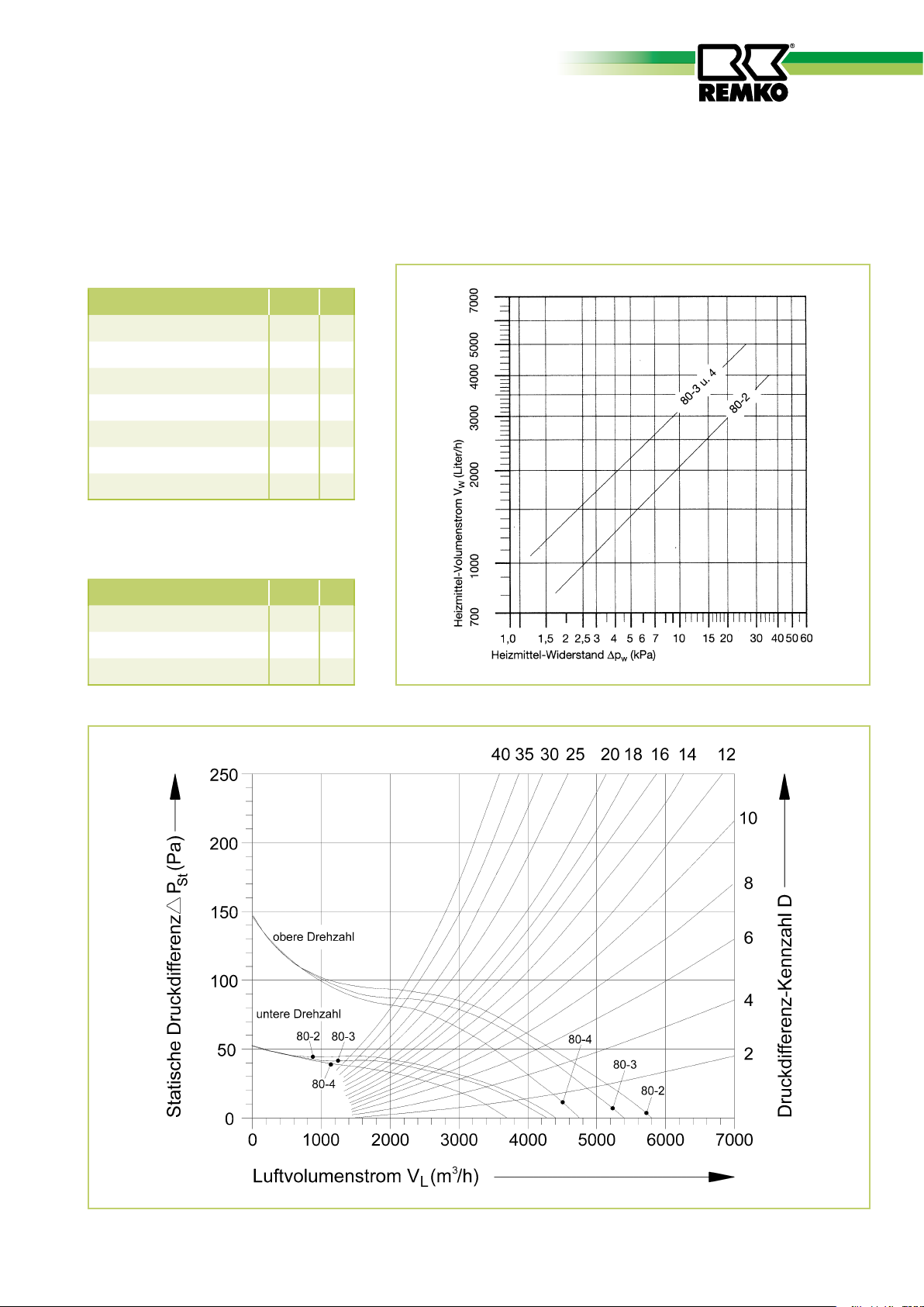
The heat outputs shown in the ratingtables are subject to variation as a result of:
Reduced air volumes with additionally mounted accessories such as
(mixed-air box, filter box, air outlet nozzle, etc.). Observe pressure difference values!
Determination of heat output and air volume when using accessories:
Actual: Unit type PWW 80-3
with filter box FK
with ceiling air outlet nozzle AD
Heating medium PWW 90/70
Air inlet temperature t
= 15°C
L1
Required: Air volume V
Heat output Q
Air outlet temperature t
Heating medium resistance ∆p
1. Determination of the air volume VL (m3/h)
The following data is provided
in the ratings tables (page 30).
Air capacity V = 5400/4300 m
Heat output Q = 50.1/42.7 kW
Air outlet temp. t
this results in an air heating of
∆t = 28/30 K
The individual pressure difference values D
(see page 31) are added:
Filter box FK 7
Air outlet nozzle AD 9
(m3/h)
L
L
L2
= 43/45°C
L2
(kw)
(°C)
W
(kPa)
3
/h
Total difference = 16
Solution from the diagram:
= 3400/2400 m3/h
V
L
We reserve the right to make changes to dimensions and design in the interest of technical advances.

31
Calculation example and explanation
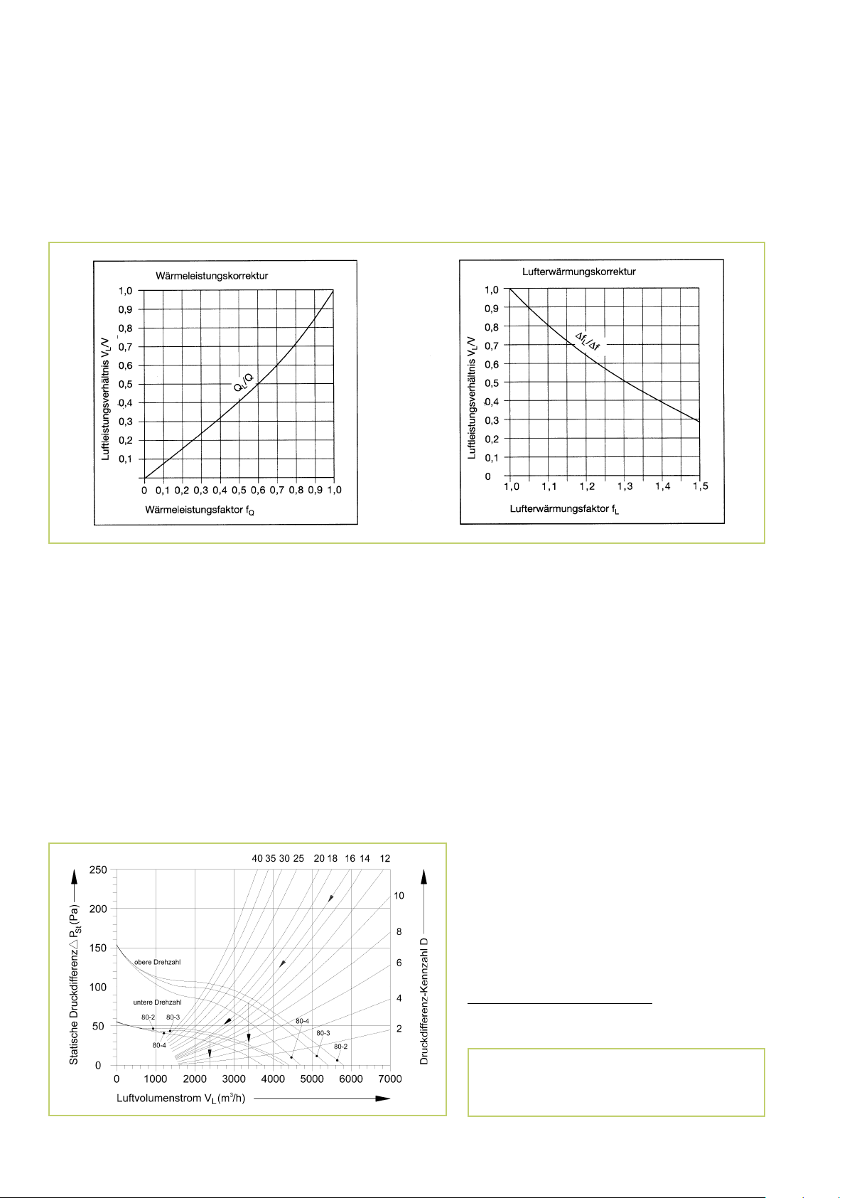
2. Heat output Q
(kW)
L
In the ratio VL to air
volume V (ratings table value), the
heat output factor can be determined from the “heat output factor
correction” f
diagram.
Q
The heat output from the ratings
table multiplied by the factor f
Q
results in the effective heat output
Q
(kW).
L
3. Air outlet temperature tL2 (°C)
For the calculation example, this results in:
Higher speed:
Air volume ratio =
Heat output correction factor f
VL 3400
V 5400
= 0.75
Q
= 0.63
Effective heat output QL = 50.1 x 0.75 = 37.6 kW
Lower speed:
V
= 2400
Air volume ratio =
Heat output correction factor f
Effective heat output Q
L
V 4300
= 0,67
Q
= 42.7 x 0.67 = 28.6 kW
L
= 0.56
Solution:
Heat output QL = 37.6/28.6 kW
For the calculation example, this results in:
From the ratio V
to air volume V
L
(ratings table value), the air heating factor can be determined.
The air heating from the ratings
table (t
- tL1) multiplied by the
L2
air heating factor fL results in the
effective air heating.
4. Heating medium resistance
Higher speed:
Air volume ratio 0.63 (see above)
Air heating factor f
Effective air heating ∆
= 1.20
L
= 28°C x 1.20 = 33.6°C [34°C]
t
L
Air outlet temperature tL2 = 34 + 15 = 49°C
Lower speed:
Air volume ratio 0.56 (see above)
Air heating factor f
Effective air heating ∆
= 1.25
L
= 30°C x 1.25 = 37.5°C [37°C]
t
L
Air outlet temperature tL2 = 37 + 15 = 52°C
Solution:
Air outlet temperature t
= 49/52°C
L2
The heating medium volume VW is calculated from:
Q
= 860 x (litre/h)
V
W
∆
= 90 – 70 = 20 °C
t
W
= 37.6 (see solution under 2.))
Q
L
This results in: V
L
∆
t
W
= 860 x = 1620 l/h
W
37.6
20
For the calculation example, given from the diagram (see Page 31) is
the heating medium resistance for the unit type 80-3:
= 2.8 kPa
Dp
W
We reserve the right to make changes to dimensions and design in the interest of technical advances.

32
REMKO PWW
Planning • Calculation • Units
■
■
Planning and selection criteria
■
Total heat requirement of room
to be heated.
■
Number of units necessary to
cover the heat requirement and
to also ensure sufficient fine heat
and air distribution in the room.
In any event, it is advantageous
to use several smaller units in order to achieve a more favourable
temperature distribution, lower
air velocities and a lower noise
level.
Required mode of operation
(circulation, mixed-air or fresh
air operation).
■
Mounting site (wall or ceiling).
■
Permissible sound pressurelevel.
■
Air inlet temperature in accessed
areas
(guide value = 35-40°C).
■
Circulated total air flow in
relation to volume
(guide value 2-3-fold air
circulation).
Determination of the required heat output, fresh air volume and air outlet temperature
Mixed-air or fresh-air that utilise
the required fresh air volumes
for the number of air changes
necessary for the room size.
■
Horizontal and vertical penetration depth of air blast required
to provide sufficient heat in the
room.
Heat capacity:
Fresh air volume:
The heating capacity Q of the REMKO heater takes into account the following components:
1. Heat requirement QH of room to be heated. (Calculation according to DIN 4701 and 4108)
2. Heat requirement QAL to heat fresh air to room temperature.
QAL = VAL · cPL · fL· (tL2 - tL1) in [kW]
Q = Q
The required fresh air volume VAL depends on the system requirements and
building regulations.
The following values are guide values and recommendations from the technical literature
Type of room Air changes x per hour Noise level dB(A)
Workshop, general 3 .... 6 70 .... 80
Warehouses 2 .... 4 60 .... 70
Textile industry 4 .... 20 about 90
Pickling shop, dye shop 5 .... 15 60 .... 70
Office rooms, small businesses 4 .... 8 about 45
Garages 4 .... 5 60 .... 70
Canteen kitchens 10 .... 30 50 .... 60
Large sales rooms, supermarkets 8 .... 10 about 60
Tennis halls 1 .... 2 45 .... 55
+ QAL in [kW]
H
VAL = X · L · W · H in [m3/h]
Air outlet temperatures: Note:
Extreme air outlet temperatures can produce uneven heat distribution and temperatures in the room. In order to provide comfortable conditions in accessed areas, we
recommend the following max. air outlet temperatures:
The data shown in the ratings tables take into account the following values:
t
L1
f
L
We reserve the right to make changes to dimensions and design in the interest of technical advances.
Comfort range 30-40°C / Industrial range 35-45°C
-15 -10 0 +15 +20
[°C]
kg
1.37 1.34 1.29 1.23 1.20
[ ]
3
m
as well as the specific heat capacity CPL
of air with 1
sure of 1013 hPa
kWs
at constant air pres-
kg · K

33
Planning • Calculation • Units
Symbol Unit Explanation
Q kW Heating capacity of air heater
Q
H
Q
AL
Q
L
V m
V
L
V
AL
V
W
t
L1
t
L2
∆
t
∆
t
W
∆
t
C
PL
ϕ
L
kW Heating requirement for room to be heated
kW Heat requirement to heat fresh air to room temperature
kW
m3/h
Effective heating capacity of air heater with mounted
accessory components
Air volume flow of air heater without mounted
3
/h
accessory components
Effective air volume flow of air heater with mounted
accessory components
m3/h Fresh air volume flow
l/h Heating medium volume flow
°C Air inlet temperature at air heater
°C Air outlet temperature at air heater
°C Air inlet/outlet temperature difference at air heater
°C Heating medium inlet/outlet temperature difference at air heater
°C
kWs
———
kg · K
kg
m
Effective air inlet/outlet temperature difference at air heater
with mounted accessory components
Specific heat capacity of air at constant pressure
Dry air density
3
Q = QH + Q
AL
QAL = VAL · CPL · ∆
VL = V · f
V
VAL = X · B · L
860 · Q
VW =
∆t = t
∆
t
W
∆
t
L
1 ———
– t
L2
= tW1 – t
= ∆
t · f
kWs
kg · K
t
W
L1
W2
L
t
L m Length of room to be heated
W m Width of room to be heated
H m Height of room to be heated
X 1/h Number of air changes in room to be heated
f
Q
f
V
f
L
∆
P
W
∆
P
ST
- Heat output factor
- Air capacity ratio
- Air heating factor
kPa Heating medium resistance (pressure loss on water-side)
Pa Static pressure difference with mounted accessory components
D - Pressure difference value with mounted accessory components
We reserve the right to make changes to dimensions and design in the interest of technical advances.
fQ = QL / Q
fV = VL / V

34
REMKO PWW
Unit dimensions
A
R
E
V
F
G
G
V = Water inlet (flow)
R = Water outlet (return)
B
98
167
C
D
The water inlet (flow) is always at the
“BOTTOM”.
Even if the units are turned during
installation and connected from the
other side.
Dim.
in
mm
A 560 640 800 880
B 440 515 630 740
C 360 360 360 390
D 403 406 412 452
E 344 419 534 644
F 80 80 80 80
G 45 45 45 45
Dim.
in
Inch
V R ¾“ R 1“ R 1¼“ R ¾“ R 1“ R 1¼“ R 1“ R 1¼“ R 1¼“ R 1¼“ R 1½“ R 1½“
R R ¾“ R 1“ R 1¼“ R ¾“ R 1“ R 1¼“ R 1“ R 1¼“ R 1¼“ R 1¼“ R 1½“ R 1½“
PWW 30 PWW 50 PWW 80 PWW 100
30-2 30-3 30-4 50-2 50-3 50-4 80-2 80-3 80-4 100-2 100-3 100-4
Unit type
Unit type
We reserve the right to make changes to dimensions and design in the interest of technical advances.

35
Technical data
Series PWW 30-2 PWW 30-3 PWW 30-4 PWW 50-5 PWW 50-3 PWW 50-4
Elec. connection V 400/3~N 400/3~N 400/3~N 400/3~N 400/3~N 400/3~N
Frequency
Power input
HZ 50 50 50 50 50 50
kW 0.13/0.10 0.13/0.10 0.13/0.10 0.26/0.18 0.26/0.18 0.26/0.18
Nominal current A 0.26/0.16 0.26/0.16 0.26/0.16 0.52/0.29 0.52/0.29 0.52/0.29
Speed
Air capacity
Sound press. level
Heating medium conn.
Heating medium
Operat. press. max.
rpm 1340/1040 1340/1040 1340/1040 1360/1020 1360/1020 1360/1020
3
/h 2250/1850 2050/1640 1850/1500 3800/3180 3400/2870 3150/2770
m
1)
dB(A) 52/46 53/48 55/49 55/50 55/51 58/54
Inch R ¾“ R 1“ R 1¼“ R ¼“ R 1“ R 1¼“
Pumped warm water or pumped hot water up to maximum 130°C
bar 16 16 16 16 16 16
Weight kg 24 26 27 31 34 36
Series PWW 80-2 PWW 80-3 PWW 80-4 PWW 100-2 PWW 100-3 PWW 100-4
Elec. connection
Frequency
Power input
Nominal current
Speed
Air capacity
Sound press. level
1)
Heating medium conn.
V
HZ
kW
A
rpm
m
dB(A)
Inch
400/3~N 400/3~N 400/3~N 400/3~N 400/3~N 400/3~N
50 50 50 50 50 50
0.42/0.28 0.42/0.28 0.42/0.28 0.76/0.47 0.76/0.47 0.76/0.47
0.76/0.46 0.76/0.46 0.76/0.46 1.50/0.81 1.50/0.81 1.50/0.81
880/670 880/670 880/670 870/650 870/650 870/650
3
5800/440 5400/4300 4730/3700 9050/7400 8250/6620 7670/6180
/h
55/49 55/49 55/49 58/54 58/54 58/54
R 1“ R 1¼“ R 1¼“ R 1¼“ R 1½“ R 1½“
Heating medium Pumped warm water or pumped hot water up to maximum 130°C
Operat. press. max.
Weight
1)
Measurement at a distance of 5m, volume of measurable space 800m 3, average reverberation time 1.4s
We reserve the right to make changes to dimensions and design in the interest of technical advances.
bar 16 16 16 16 16 16
kg 44 47 51 58 60 68

REMKO EUROPE-WIDE
… and somewhere near you!
Take advantage of our experience and consulting services
Consulting
Through intensive training, we ensure that the expert knowledge of our
consultants is always up-to-date. This
has given us the reputation of being
more than just a good, reliable supplier:
REMKO, a partner,
that helps solve problems.
Sales
REMKO not only provides an extensive
sales network in Germany and abroad,
but also unusually highly qualified sales
experts.
REMKO sales representatives are more
than just salespeople: they are also
customer consultants in the area of air
conditioning and heating technology.
Customer service
Our units operate precisely and reliably. If a fault should occur, REMKO
Customer Service is there to help you.
Our extensive network of experienced
specialised dealers guarantees you a fast
and reliable service.
REMKO GmbH & Co. KG
Air Conditioning and Heating Technology
Im Seelenkamp 12 · D-32791 Lage
P.O. Box 1827 ·D-32777 Lage
Telephone +49 52 32 606-0
Fax +49 5232 606-2 60
E-mail info@remko.de
Internet www.remko.de
Subject to technical changes, errors and omissions excepted!
 Loading...