

Page 1
Assembly and operating instructions
REMKO MXD 202, MXD 262, MXD 352, MXD 522
Ceiling cassette for inverter multi-split designed outdoor units
0047-2013-05 Edition 1, en_GB
Read the instructions prior to performing any task!
Page 2
Read these operating instructions carefully before commissioning / using this device!
These instructions are an integral part of the system and must
always be kept near or on the device.
Subject to modifications; No liability accepted for errors or misprints!
Installation and operating instructions (translation of the original)
Page 3

Table of contents
1 Safety and usage instructions............................................................................................................. 4
1.1 General safety notes....................................................................................................................... 4
1.2 Identification of notes...................................................................................................................... 4
1.3 Personnel qualifications.................................................................................................................. 4
1.4 Dangers of failure to observe the safety notes................................................................................ 4
1.5 Safety-conscious working............................................................................................................... 4
1.6 Safety notes for the operator........................................................................................................... 5
1.7 Safety notes for installation, maintenance and inspection.............................................................. 5
1.8 Unauthorised modification and changes......................................................................................... 5
1.9 Intended use................................................................................................................................... 5
1.10 Warranty........................................................................................................................................ 5
1.11 Transport and packaging.............................................................................................................. 6
1.12 Environmental protection and recycling........................................................................................ 6
2 Technical data....................................................................................................................................... 7
2.1 Technical data................................................................................................................................. 7
2.2 Unit dimensions .............................................................................................................................. 8
3 Design and function.............................................................................................................................. 9
3.1 Equipment description..................................................................................................................... 9
3.2 Combinations................................................................................................................................ 10
4 Operation............................................................................................................................................. 12
5
Installation instructions for qualified personnel.............................................................................. 22
6 Installation........................................................................................................................................... 23
7 Condensate connection and safe drainage...................................................................................... 27
8 Electrical wiring................................................................................................................................... 28
8.1 General information....................................................................................................................... 28
8.2 Unit connection............................................................................................................................. 28
8.3 Electrical connection diagram....................................................................................................... 30
8.4 Choice of unit................................................................................................................................ 31
8.5 Electrical circuit diagram............................................................................................................... 32
9 Commissioning................................................................................................................................... 34
10 Shut-down............................................................................................................................................ 35
11 Troubleshooting and customer service ........................................................................................... 36
12 Care and maintenance........................................................................................................................ 39
13 Exploded view of the unit and spare parts list................................................................................. 41
13.1 Exploded view ............................................................................................................................ 41
13.2 Spare parts list............................................................................................................................ 42
14 Index..................................................................................................................................................... 43
3
Page 4
REMKO MXD
1
1.1
Carefully read the operating manual before commissioning the units for the first time. It contains
useful tips and notes such as hazard warnings to
prevent personal injury and material damage.
Failure to follow the directions in this manual not
only presents a danger to people, the environment
and the system itself, but will void any claims for
liability.
Keep this operating manual and the refrigerant
data sheet near to the units.
1.2
This section provides an overview of all important
safety aspects for proper protection of people and
safe and fault-free operation.The instructions and
safety notes contained within this manual must be
observed in order to prevent accidents, personal
injury and material damage.
Notes attached directly to the units must be
observed in their entirety and be kept in a fully
legible condition.
Safety notes in this manual are indicated by symbols. Safety notes are introduced with signal words
which help to highlight the magnitude of the danger
in question.
Safety and usage instructions
General safety notes
Identification of notes
DANGER!
CAUTION!
This combination of symbol and signal word
warns of a potentially hazardous situation,
which if not avoided may cause injury or material and environmental damage.
NOTICE!
This combination of symbol and signal word
warns of a potentially hazardous situation,
which if not avoided may cause material and
environmental damage.
This symbol highlights useful tips and recommendations as well as information for efficient
and fault-free operation.
1.3
Personnel qualifications
Personnel responsible for commissioning, operation, maintenance, inspection and installation must
be able to demonstrate that they hold a qualification which proves their ability to undertake the
work.
Contact with live parts poses an immediate
danger of death due to electric shock. Damage
to the insulation or individual components may
pose a danger of death.
DANGER!
This combination of symbol and signal word
warns of a situation in which there is immediate
danger, which if not avoided may be fatal or
cause serious injury.
WARNING!
This combination of symbol and signal word
warns of a potentially hazardous situation,
which if not avoided may be fatal or cause
serious injury.
Dangers of failure to observe
1.4
the safety notes
Failure to observe the safety notes may pose a risk
to people, the environment and the units. Failure to
observe the safety notes may void any claims for
damages.
In particular, failure to observe the safety notes
may pose the following risks:
n The failure of important unit functions.
n The failure of prescribed methods of mainte-
nance and repair.
n Danger to people on account of electrical and
mechanical effects.
1.5
Safety-conscious working
The safety notes contained in this manual, the
existing national regulations concerning accident
prevention as well as any internal company
working, operating and safety regulations must be
observed.
4
Page 5

1.6
Safety notes for the operator
The operational safety of the units and components is only assured providing they are used as
intended and in a fully assembled state.
n The units and components may only be set up,
installed and maintained by qualified personnel.
n Protective covers (grille) over moving parts
must not be removed from units that are in
operation.
n Do not operate units or components with
obvious defects or signs of damage.
n Contact with certain unit parts or components
may lead to burns or injury.
n The units and components must not be
exposed to any mechanical load, extreme
levels of humidity or extreme temperature.
n Spaces in which refrigerant can leak sufficient
to load and vent. Otherwise there is danger of
suffocation.
n All housing parts and device openings, e.g. air
inlets and outlets, must be free from foreign
objects, fluids or gases.
n The units must be inspected by a service tech-
nician at least once annually. Visual inspections and cleaning may be performed by the
operator when the units are disconnected from
the mains.
Safety notes for installation,
1.7
maintenance and inspection
n Appropriate hazard prevention measures must
be taken to prevent risks to people when performing installation, repair, maintenance or
cleaning work on the units.
n The setup, connection and operation of the
units and its components must be undertaken
in accordance with the usage and operating
conditions stipulated in this manual and comply
with all applicable regional regulations.
n Local regulations and laws such as Water
Ecology Act must be observed.
n The power supply should be adapted to the
requirements of the units.
n Units may only be mounted at the points pro-
vided for this purpose at the factory. The units
may only be secured or mounted on stable
structures, walls or floors.
n Mobile units must be set up securely on suit-
able surfaces and in an upright position. Stationary units must be permanently installed for
operation.
n The units and components should not be oper-
ated in areas where there is a heightened risk
of damage. Observe the minimum clearances.
n The units and components must be kept at an
adequate distance from flammable, explosive,
combustible, abrasive and dirty areas or
atmospheres.
n Safety devices must not be altered or
bypassed.
Unauthorised modification
1.8
and changes
Modifications or changes to units and components
are not permitted and may cause malfunctions.
Safety devices may not be modified or bypassed.
Original replacement parts and accessories
authorised by the manufactured ensure safety. The
use of other parts may invalidate liability for
resulting consequences.
1.9
Intended use
Depending on the model, the units and the additional fittings with which they are equipped are only
intended to be used as an air-conditioner for the
purpose of cooling or heating the air in an
enclosed space.
Any different or additional use is a non-intended
use. The manufacturer/supplier assumes no liability for damages arising from a non-intended use.
The user bears the sole risk in such cases.
Intended use also includes working in accordance
with the operating and installation instructions and
complying with the maintenance requirements.
The threshold values specified in the technical
data must not be exceeded.
1.10
For warranty claims to be considered, it is essential
that the ordering party or its representative complete and return the "certificate of warranty" to
REMKO GmbH & Co. KG at the time when the
units are purchased and commissioned.
The warranty conditions are detailed in the "General business and delivery conditions". Furthermore, only the parties to a contract can conclude
special agreements beyond these conditions. In
this case, contact your contractual partner in the
first instance.
Warranty
5
Page 6
REMKO MXD
1.11
The devices are supplied in a sturdy shipping container. Please check the equipment immediately
upon delivery and note any damage or missing
parts on the delivery and inform the shipper and
your contractual partner. For later complaints can
not be guaranteed.
Plastic films and bags etc. are dangerous
toys for children!
Why:
- Leave packaging material are not around.
- Packaging material may not be accessible to
children!
1.12
Disposal of packaging
All products are packed for transport in environmentally friendly materials. Make a valuable contribution to reducing waste and sustaining raw materials. Only dispose of packaging at approved
collection points.
Transport and packaging
WARNING!
Environmental protection and recycling
Disposal of equipment and components
Only recyclable materials are used in the manufacture of the devices and components. Help protect
the environment by ensuring that the devices or
components (for example batteries) are not disposed in household waste, but only in accordance
with local regulations and in an environmentally
safe manner, e.g. using certified firms and recycling specialists or at collection points.
6
Page 7
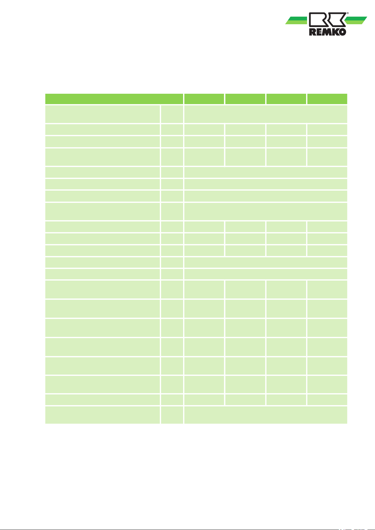
2
2.1
Technical data
Technical data
Series MXD 202 MXD 262 MXD 352 MXD 522
Operating mode
Nominal cooling output
Nominal heating output
1)
2)
kW 2,05 2,64 3,51 5,27
kW 2,34 3,22 3,81 6,00
Operating range (room volume),
approx.
m
Ceiling cassette for inverter multi-split designed outdoor
units for cooling and heating
3
60 80 110 160
Room-temperature adjustment range °C +17 to +30
Operating range °C +17 to +32
Refrigerant
Operating pressure max. / per cooling
circuit
kPa 4200 / 1500
R 410A
4)
Air flow volume per speed setting m³/h 380/445/580 380/445/580 500/570/720 635/690/800
3)
Sound press. level per speed setting
dB (A) 40/44/48 40/44/48 40/43/48 40/43/46
Sound power (Turbo mode) dB (A) 52 53 54 54
Power supply V/Hz 230 / 1~ / 50
Protection class IP X 0
Nom. electrical power consumption,
cooling
1)
Nom. electrical power consumption,
heating
2)
Nom. electrical current consumption,
cooling
1)
Nom. electrical power consumption,
heating
2)
Refrigerant connection - injection line
Coolant connection - suction line
W 15 15 20 102
W 15 15 20 102
A 0,06 0,06 0,08 0,44
A 0,06 0,06 0,08 0,44
Inch
(mm)
Inch
(mm)
1/4 (6,35) 1/4 (6,35) 1/4 (6,35) 1/4 (6,35)
3/8 (9,52) 3/8 (9,52) 3/8 (9,52) 1/2 (12,70)
Condensate drain mm 25 25 25 25
Condensate pump, max. pumping
capacity
mm
WS
500
7
Page 8
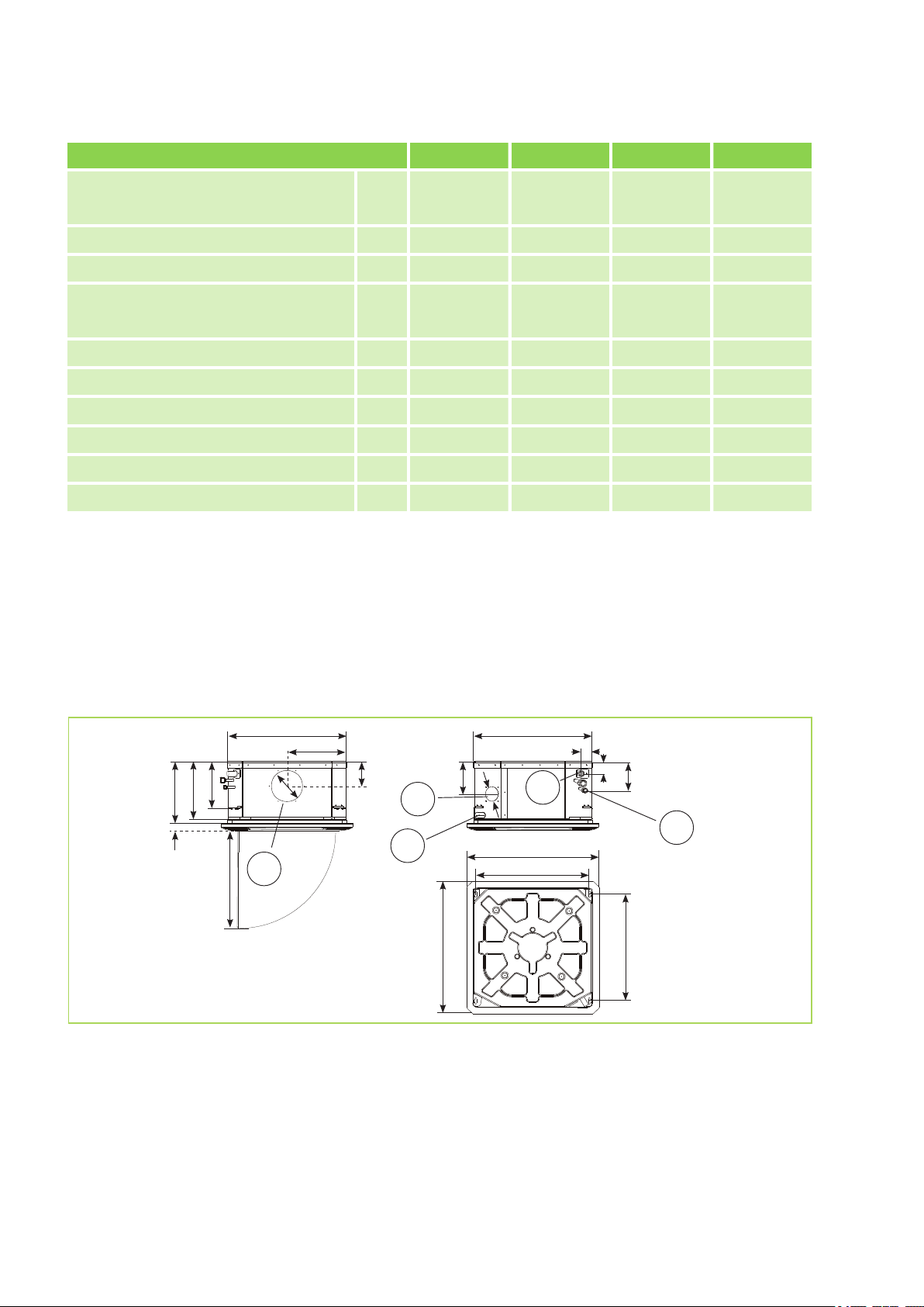
175
570
285
215
260
28030
150
65
115
415
570
40
50
140
522
647
522
647
2
1
4
3
5
REMKO MXD
Series MXD 202 MXD 262 MXD 352 MXD 522
Dimensions ceiling cassette
Length mm 570 570 570 570
Width mm 570 570 570 570
Depth mm 260 260 260 260
Dimensions cover
Length mm 647 647 647 647
Width mm 647 647 647 647
Depth mm 50 50 50 50
Weight kg 15,0 16,0 17,0 18,0
Weight cover kg 2,5 2,5 2,5 2,5
Serial number 1324... 1325... 1326... 1327...
Computerised part no. 1623252 1623257 1623262 1623267
1)
Air intake temp. TK 27°C / FK 19°C, outdoor temp. TK 35°C / FK 24°C, max. air volume, 5m pipe length
2)
Air intake temperature TK 20°C outdoor temperature TK 7°C, FK 6°C, max. air volume, 5m pipe length
3)
Distance 1 m free field
4)
Contains greenhouse gas according to Kyoto protocol
For details of the energy efficiency see operating instructions corresponding external unit
2.2
Unit dimensions
Fig. 1: Dimensions MXD 202-522 (All measurements in mm)
1: Adjoining room connection
2: Fresh air connection
3: Implementation of electrical control line
We reserve the right to modify the dimensions and design as part of the ongoing technical development
process.
4: Condensate drain
5: Refrigerant connection
8
Page 9
B
A
4
3
5
6
1a
1b
2
7b
3 3
7a
8b8a
9b9a
2
1
4
3
3
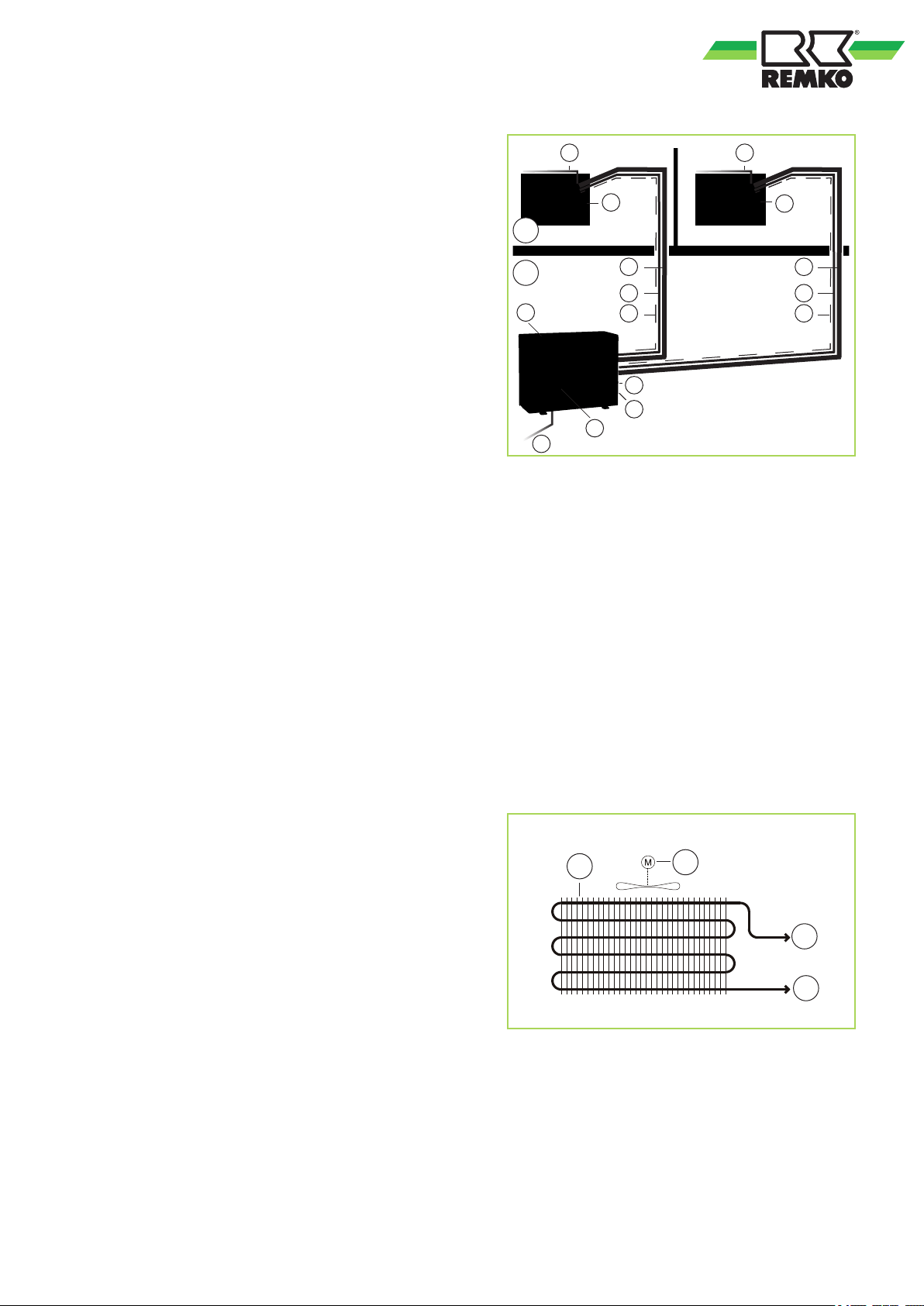
3.1
The indoor unit serves to extract heat from the
indoor room being cooled. The outdoor unit then
expels this heat to the outside.
If combined heating/cooling units are operated as
heaters, the heat absorbed by the outdoor unit can
be discharged by the indoor unit into the room
being heated.
The unit series has priority "heating", this means
that units that are in heating or automatic mode,
other units in the system that are in cooling mode
can switch off.
The unit is designed for installation high up on
indoor walls.
Operation takes place using an infrared remote
control.
The indoor unit consists of a fin vaporiser, vaporiser fan, controller and condensation pan.
The indoor unit can be combined with REMKO outdoor units of series MVT 601DC, 901DC und
1051DC with sufficient combinations. The outdoor
component is controlled via the controller of the
indoor unit.
Cabled remote control and condensation pump are
available as an accessory.
Design and function
Equipment description
Fig. 2: System layout
(In this example: MVT 901 DC with 2 MXD 352)
A: Outdoor area
B: Indoor area
1 a,b: Indoor units
2: Outdoor unit
3: Condensate drain
4: Condenser fan
5: Power output
6: Shut-off valve
7 a,b: Suction pipe
8 a,b: Injection pipe
9 a,b: Control line
Refrigerant pipes are used to connect the indoor
unit to the outdoor unit.
Fig. 3: Schematic of refrigerant circuit
1: Evaporator
2: Evaporator fan
3: Connection suction pipe
4: Connection injection pipe
9
Page 10
REMKO MXD
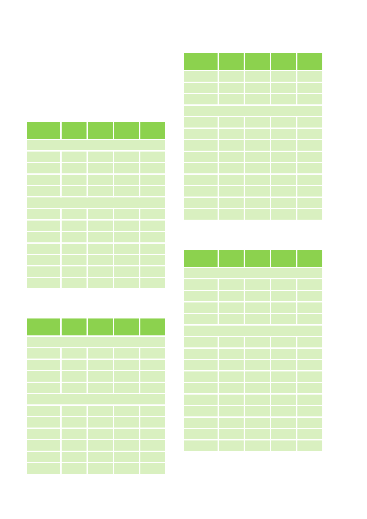
3.2
Combinations
Indoor units
The indoor units MXD 202-522 can be combined
with MVT 601DC, 901DC und 1051DC series outdoor units. The following combinations are possible.
Outdoor unit MVT 601 DC
Combination
One indoor unit
1
2
3
4
Two indoor units
5
6
MXD
202
l
ll
MXD
262
l
ll
MXD
352
l
MXD
522
l
Combination
11
12
13
Three indoor units
14
15
16
17
18
19
20
21
22
MXD
202
lll
ll l
ll
l ll
l l l
l
ll
MXD
262
lll
ll l
MXD
352
l
l l
l l
l
ll
MXD
522
l
l
7
8
9
10
11
Outdoor unit MVT 901 DC
Combination
One indoor unit
1
2
3
4
Two indoor units
5
l l
l
l
MXD
202
l
ll
l l
MXD
262
l
ll
l
MXD
352
l
l
MXD
522
l
Outdoor unit MVT 1051 DC
Combination
One indoor unit
1
2
3
4
Two indoor units
5
6
7
8
9
10
11
MXD
202
l
ll
l l
l
l
MXD
262
l
ll
l l
MXD
352
l
ll
l
MXD
522
l
l
6
7
8
9
10
l l
l
l
ll
ll
l
12
l
13
14
l
l l
ll
l
10
Page 11
Outdoor unit MVT 1051 DC (Fortsetzung)
Combination
Three indoor units
15
16
17
18
19
20
21
22
23
24
25
26
MXD
202
lll
ll l
ll
l ll
l l l
l
ll
l l
MXD
262
lll
ll l
l ll
MXD
352
lll
l
ll
MXD
522
l
l
Combination
47
48
49
50
51
52
53
54
55
56
MXD
202
ll
lll
MXD
262
l ll
l l l l
lll
l
l
ll l l
ll ll
l lll
MXD
352
ll l
lll
MXD
522
ll
l
l
l
27
28
29
30
31
32
Four indoor units
33
34
35
36
37
38
39
40
41
l
ll
l
llll
llll
lll l
lll
ll ll
ll l l
l lll
l ll l
l l l
l
l l
ll l
llll
l
l
ll
ll
42
43
44
45
46
11
ll
l l ll
ll l
ll
lll l
ll
l l
l
Page 12
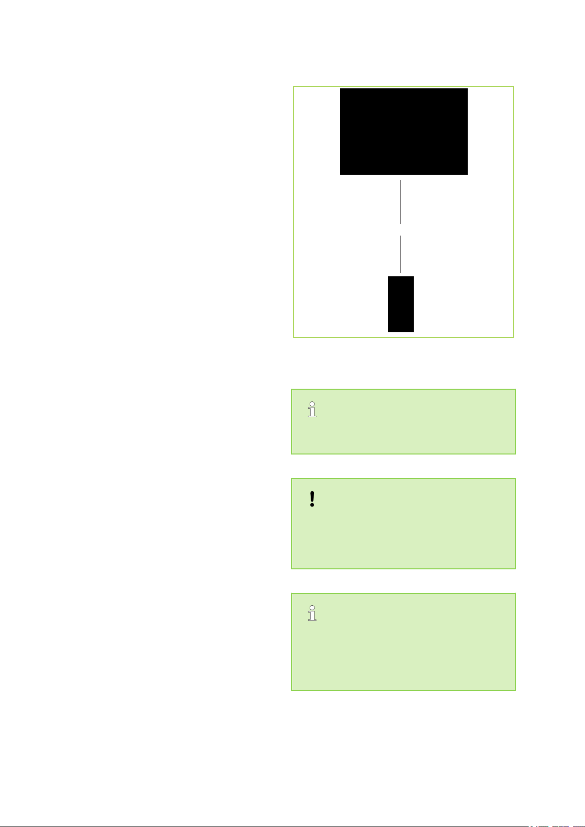
max. 6 m
REMKO MXD
4
The indoor unit is easily operated using the
standard infrared remote control. The indoor unit
beeps to acknowledge the correct transmission of
data. If it is not possible to program the indoor unit
using the remote control, it can also be manually
operated.
Manual operation
The indoor units can be started manually. Press
the "MANUAL" button on the receiver unit of the
cover to activate automatic and the ooling mode
then. The third press turns the unit off. A pressing
again switches back to automatic mode. Within the
whole plant, the unit having manually setting the
cooling mode will be the guide unit. In manual
mode, the following settings apply:
Cooling mode: 24 °C, fan speed: AUTO
Heating mode: 26 °C, fan speed: AUTO
Pressing any button on the infrared remote control
interrupts manual mode.
Infrared remote control
The infrared remote control sends the programmed
settings over a distance of up to 6 m from the
receiver of the indoor unit. Data will only be
received correctly if the remote control is pointed at
the receiver and no objects obstruct the transmission path.
First insert the batteries supplied on delivery (2 x
type AAA) into the remote control. To do so, pull
off the flap of the battery compartment and insert
the batteries according to their polarity (see markings).
Operation
Fig. 4: Maximum distance
Alarms are indicated by a code (see chapter
Troubleshooting and customer service).
NOTICE!
Immediately replace flat batteries with a new
set, otherwise there is a risk of leakage. It is
recommended that the batteries are removed if
the equipment is shut down for longer periods.
Help save on energy consumption in stand-by
mode! If the device, system or component is
not in use, we recommend disconnecting the
power supply. Components with a safety function is excluded from our recommendation!
12
Page 13
Display on the indoor unit
2
1
4
6
3
5
4
1
7
8
10
11
3
2
13
9
5
6
12
14
15
1
2
3
4
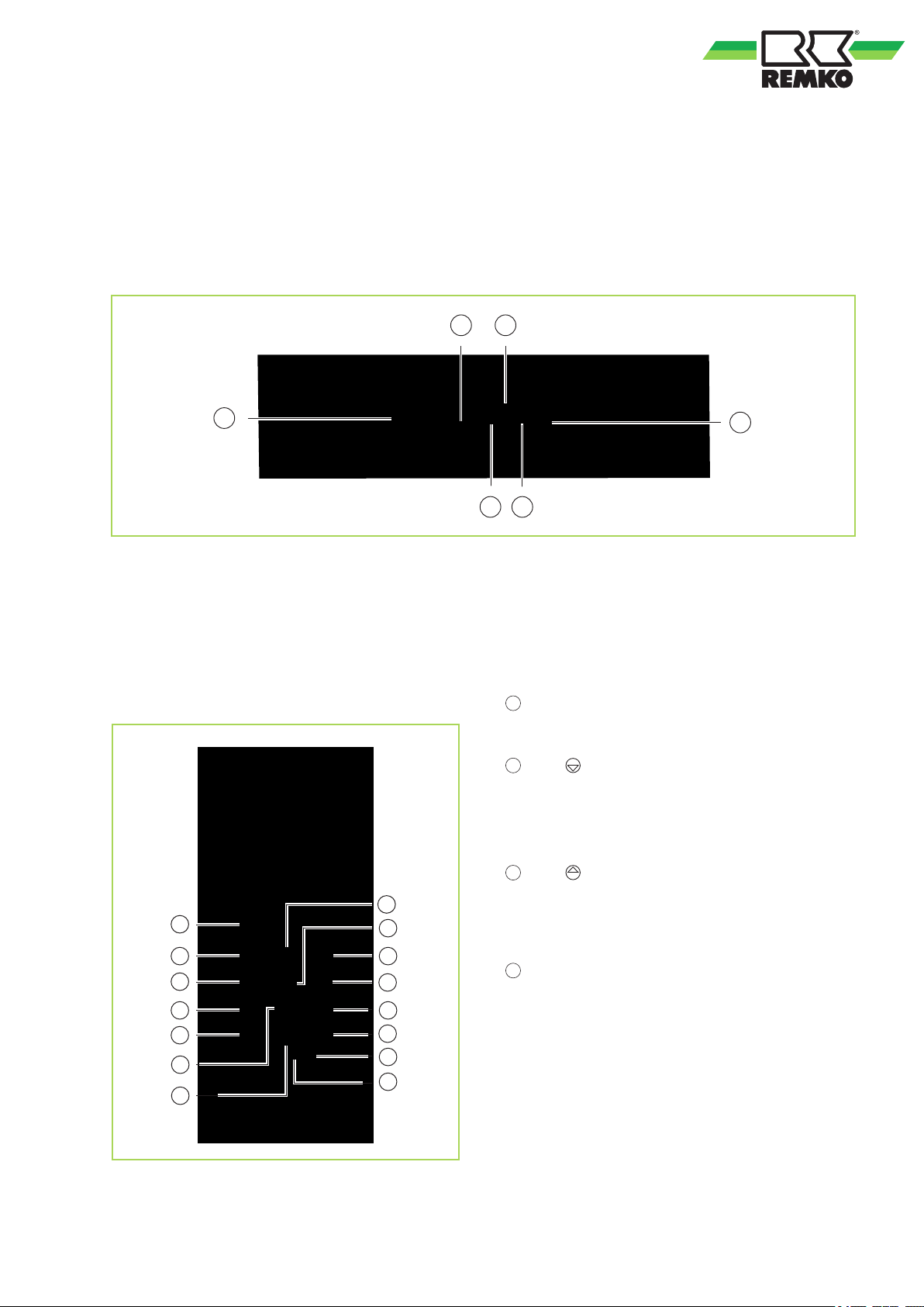
The lit LED indicators show the settings:
LED OPERATION green = unit is on
LED TIMER yellow = timer is programmed
LED DEF/FAN red = defrosting active / air circulation mode
LED ALARM red = presence of a fault
Fig. 5: Display on the indoor unit
1: Unit for receiving signals from the remote con-
trol
2: Operation indicator
3: Timer indicator
Keys on the remote control
Fig. 6: Keys of the remote control
4: Key for manual operation
5: Fan Defrost
6: Alarm indicator
Key „ON/OFF“
Press this key to operate the unit.
Key " "
With this key, the desired temperature can be
decreased to 17°C.
Key " "
With this key, the desired temperature can be
increased up to 30°C.
Key „MODE“
Press this key to select the operating mode. The
indoor unit has 5 modes:
1. Automatic mode
In this mode, the unit works in cooling or in heating
mode.
2. Cooling mode
In this mode, the warm air in the room is cooled
down to the desired temperature.
13
Page 14
5
6
7
8
9
10
11
12
13
14
15
REMKO MXD
3. Dehumidification mode
In this mode, the room is dehumidified, thereby the
room temperature significantly lowered. Influencing
temperature and fan speed in this mode not possible.
4. Heating mode
In this mode, the warm air in the room is warmed
to the desired temperature.
5. Air circulation mode
In this mode, the air in the room is circulated with
no change in temperature.
Key „FAN“
Press this key to set the desired fan speed. 4
speeds are available:
Automatic, high, medium and low fan speed.
Key „LED/FOLLOW ME“
Short press this button enables / disables the LED
display on the indoor unit.
With pressing this key longer then 2 sec., the
sensing of the room temperature is moved from the
interior unit to the remote control. The temperature
measured on the remote control is then transmitted
to the interior unit in certain intervals.
Key „SLEEP“
Pressing this key will automatically increase the
target temperature by 1 °C every hour in cooling
mode, and decrease the target temperature by 1
°C every hour in heating mode.
Key „TIMER ON"
This button initiates the automatic switch-on time
for the unit. Each time the key is pressed, the automatic time setting increases in increments of 30
minutes. Once the time setting shows 10.0, the
automatic time setting increases in increments of
60 minutes each time the key is pressed. In order
to cancel the automatic time setting, simply set the
automatic switch-on time to 0.0.
Key „TIMER OFF“
This button initiates the automatic switch-off time
for the unit. Each time the key is pressed, the automatic time setting increases in increments of 30
minutes. Once the time setting shows 10.0, the
automatic time setting increases in increments of
60 minutes each time the key is pressed. In order
to cancel the automatic time setting, simply set the
automatic switch-off time to 0.0.
Key „TURBO“
The „TURBO“- key allows the preset temperature
to be reached in the shortest possible time.
Pressing this key in "Cooling mode" causes the
unit to blow a blast of cooling air into the room at a
very high fan speed.
Key „SHORTCUT“
By first press on this button the setpoint to 24 ° C
and the fan speed is set to automatic. When the
button is pressed while the remote control during
the operation, the unit resets to the last setting
operating mode.
Key „SWING“
This key directly activates the oscillating function of
the fins for better air distribution in the room.
Key „DIRECT“
The position of the exhaust fins is determined with
this button. The fins change by pressing of the
„DIRECT“-key they position by 6°.
Key „LOCK“
This key can be used to lock the keys on the
remote control. Press again this key and the
remote control can be used again.
Key „RESET“
Press the "RESET" key to reset all settings to factory settings.
14
Page 15
10
6
7
8
9
54321
11 12 13
Remote control display
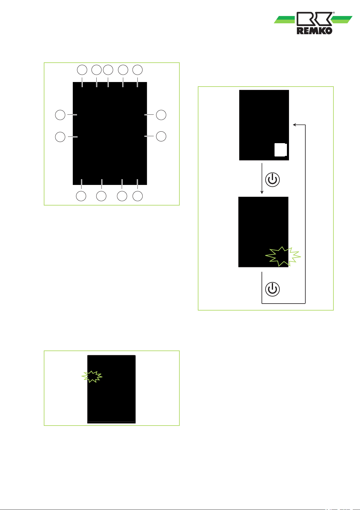
Fig. 7: Remote control display
1: Automatic mode
2: Cooling mode
3: Dehumidifying mode
4: Heating mode
5: Air circulation mode
6: Indicator signal transmission
7: Display for temperature/timer
8: Timer activated/deactivated
9: Display of fan speed
10: Sleep-mode aktivated
11: Follow-Me function aktivated
12: Remote control locked
13: Display on/off
Remote control on/off
The remote control's on/off function is shown at the
lower right of the remote control by a "circular
symbol".
Fig. 9: Remote control on/off
Key functions
A symbol is shown on the display to indicate that
the settings are being transferred.
Fig. 8: Key functions
15
Page 16
5
4
3
2
1
MODE
MODE
MODE
MODE
REMKO MXD
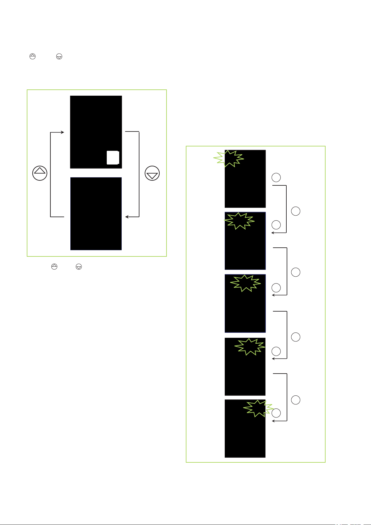
" " and " "-keys
Using the key, the target temperature can be
adjusted up or down by 1°C. The temperature
range lies between 17°C and 30°C
"MODE" key
Use the MODE key to select between individual
operating modes.
A total of 5 modes are available:
1. Automatic
2. Cooling
3. Dehumidifying
4. Heating
5. Air circulation
Fig. 10: " " and " "-keys
Fig. 11: Mode key
16
Page 17
"Automatic" mode
In automatic mode, the controller autonomously
selects between heating, circulation or cooling
mode based on the room temperature Tr and the
selected target value Ts. The target value can be
adjusted between 17°C and 30°C by means of the
"
" and " ". The fan speed is selected automati-
cally.
Fig. 12: "Automatic" mode
Funktion:
Tr<Ts=1 °C, then operating mode "Heating" is
selected.
Tr>Ts=2 °C, then operating mode "Cooling" is
selected.
Tr<-1 °C...Ts...+2 °C, then operating mode "Circu-
lation" is selected.
If after the compressor is shut down and not
required for more than 15 mins. within an operating
mode, then, in the event that the room temperature
deviates, the corresponding mode heating,
cooling or circulation will be selected again.
„Dehumidification“ mode
It is recommended that the target temperature be
set to 24°C in dehumidifying mode. Due to the low
temperature of the refrigerant, the dew point of the
air at the condenser is undercut. The excess moisture in the air is condensed by the vaporiser, the
room is dehumidified.
Fig. 13: "Dehumidification“ mode
„Cooling“ mode
In cooling mode, the air in the room is cooled down
to the adjusted nominal temperature. The desired
room temperature is set with the " " and " " keys
in 1 °C increments. If the room temperature is 0.5
°C above the selected nominal temperature, then
the interior unit starts to cool down the air in the
room. If the temperature falls to approx. 1 °C below
the set room temperature, the controller will switch
off the cooling function. To protect the compressor,
the controller only turns cooling on again after a
waiting period of 3 minutes.
The heating mode has priority!
Turns on the indoor unit to the heating mode,
switch off the other indoor units from which are
in cooling mode, the cooling. During heating
operation can not be cooled.
Fig. 14: „Cooling“ mode
17
Page 18
4
3
2
1
FAN
FAN
FAN
FAN
REMKO MXD
„Heating“ mode
In the heating mode, you can heat the room in
spring or fall. The selected room temperature is set
using the "
" and " " keys in 1 °C increments. If
the room temperature is 1 °C below the selected
target temperature, the indoor unit starts to heat
the air in the room. If the set room temperature is
exceeded by approx. 1 °C, the controller will switch
off the heater function. To protect the compressor,
the controller will wait 3 minutes before switching
on the heating mode again. The fan operation
starts only at a temperature of 32 ° C at the heat
exchanger.
Fig. 15: „Heating“ mode
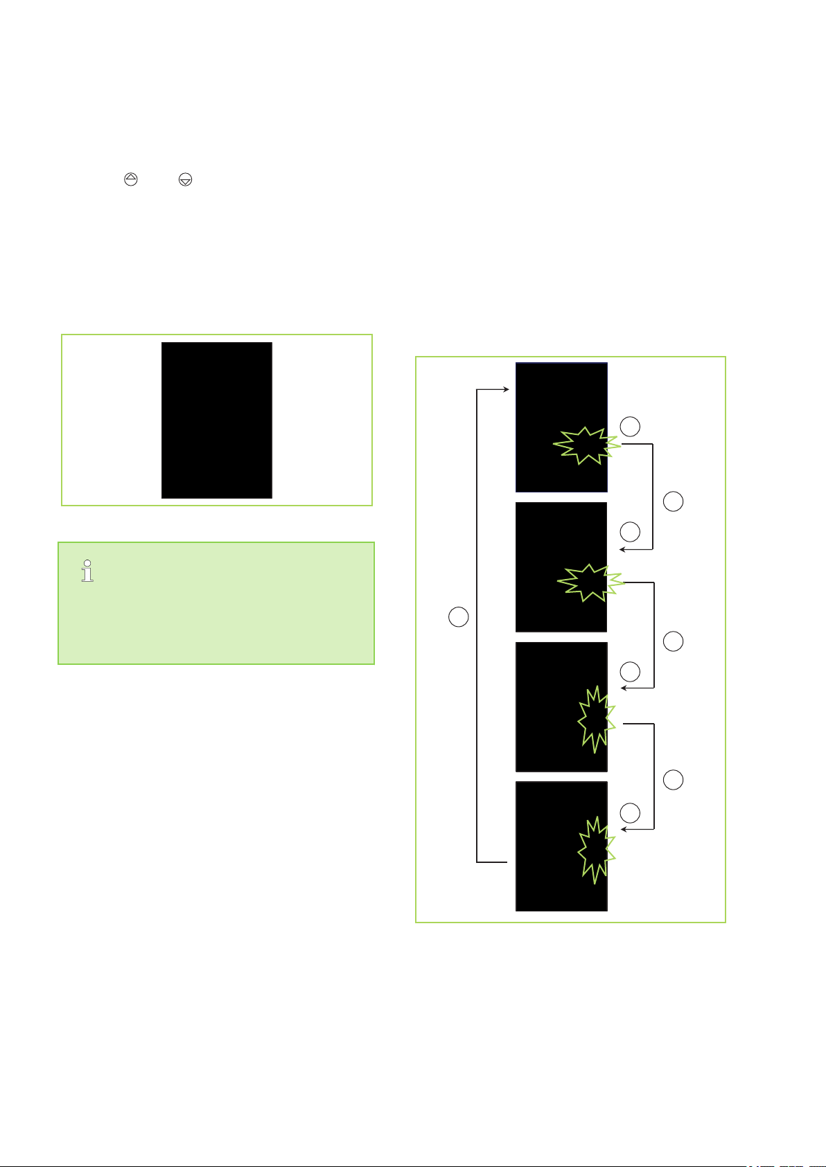
„FAN“ key
Function
1. Automatic
2. Low
3. Medium
4. High
Automatic function:
<ca. 1,5 °C = low level
> ca. 1,5 °C = middle level
> ca. 3,5 °C = high level
The heating mode has priority!
Turns on the indoor unit to the heating mode,
switch off the other indoor units from which are
in cooling mode, the cooling. During heating
operation can not be cooled.
Fig. 16: "Fan" key
18
Page 19
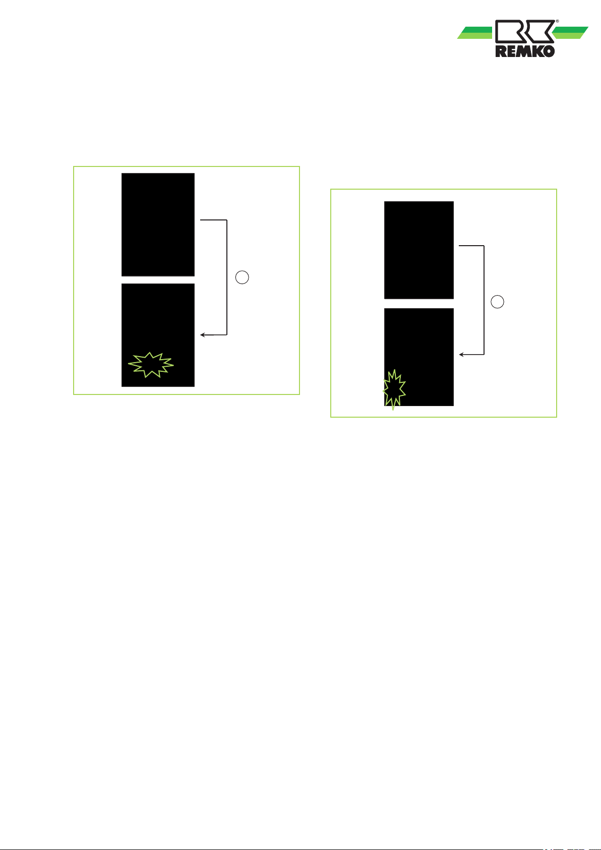
LED
FOLLOW ME
> 2 sec.
SLEEP
„Follow-Me“ function
This function allows the transfer the measurement
of the room temperature from the indoor unit to the
remote control. Measuring the temperature at the
remote control is then transmitted at intervals to
the indoor unit.
„SLEEP“ key
A programming function is activated using this key,
which increases the target temperature in cooling
mode by 1°C after one hour and by 2°C after 2
hours. In heating mode, the target temperature is
decreased by 1 °C after one hour by 2 °C after 2
hours. The unit switches off automatically after 8
hours.
Fig. 17: „Follow-Me“ function
Fig. 18: "Sleep" key
19
Page 20
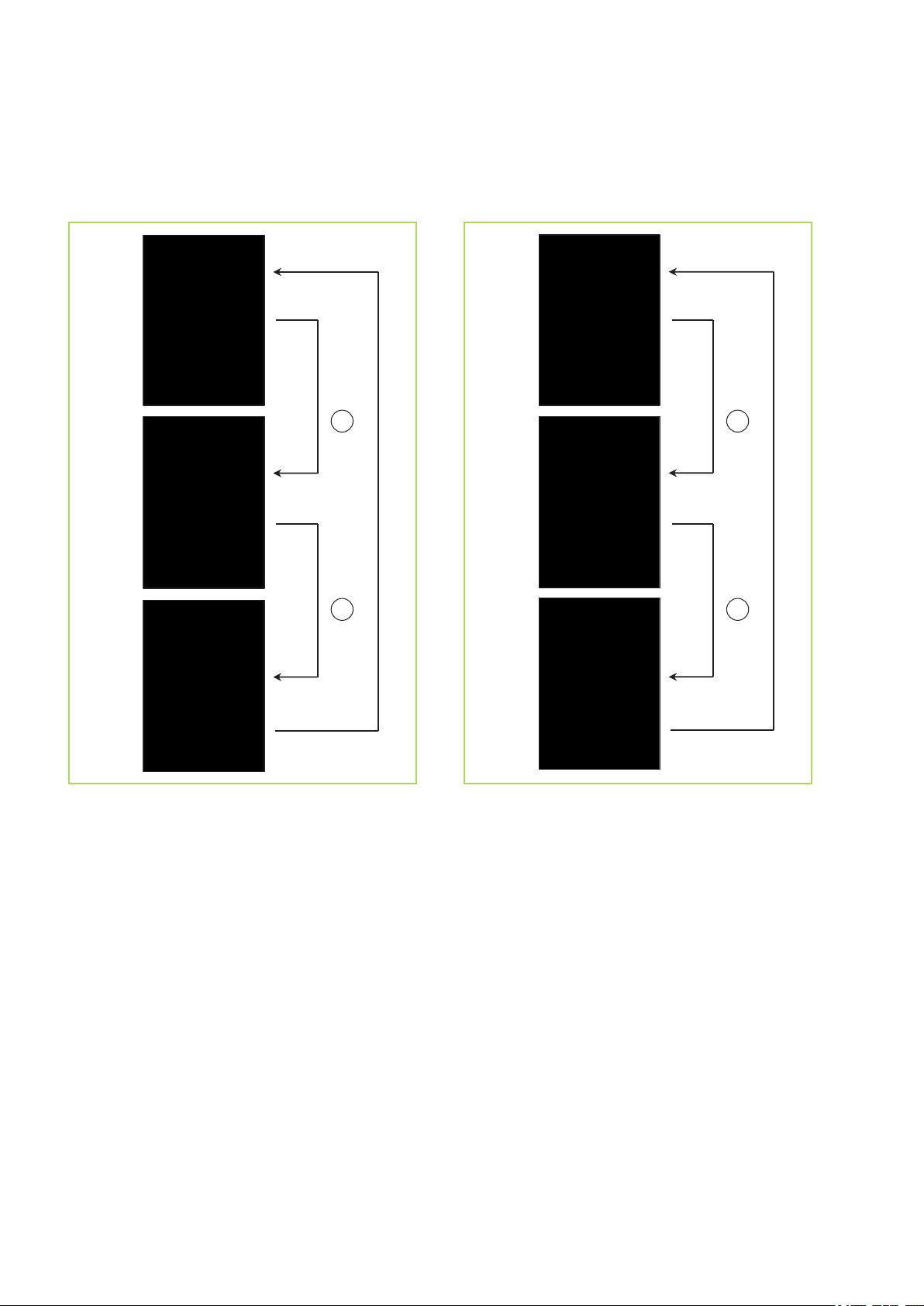
3 sec.
TIMER
ON
TIMER
ON
3 sec.
TIMER
OFF
TIMER
OFF
REMKO MXD
„TIMER ON“ key
This key allows the unit is switched off in an
adjustable interval of 30 minutes (0.5 h) to switch
on the unit.
„TIMER OFF" key
This key allows the unit is switched on in an
adjustable interval of 30 minutes (0.5 h) to switch
off the unit.
Fig. 19: „TIMER ON“ key
Fig. 20: „TIMER OFF" key
20
Page 21
TURBO
SELF CLEAN
LOCK
RESET
A
B
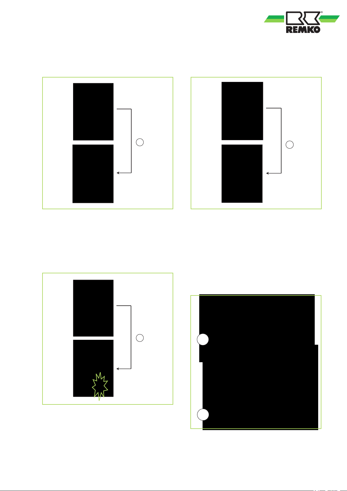
„TURBO/FP“ key
The maximum fan speed and the compressor is
activated by pressing the "TURBO/FP" key.
Fig. 21: „TURBO/FP“ key
„RESET“ key
With this recessed key the remote control can be
reset.
Fig. 23: „RESET“ key
„LOCK“ key
The functions of the remote control can be disabled with this recessed key. This can prevent accidental adjustment of the set values.
Cable remote control
Connection of an optional cable remote control
The plug for connecting a cable remote control is
located on the panel the ceiling cassette (s.
Fig. 24, [A]). The 5-wired cable, coming from the
display board, is provided with the designations AE (s. Fig. 24, [B]).
Fig. 22: „LOCK“ key
Fig. 24: Connection of a cable remote control
21
Page 22
300
300
300
300
300
REMKO MXD
5
Important notes prior to installation
Observe the operating manuals for the indoor unit
and the outdoor unit when installing the entire
system.
n Transport the unit in its original packaging as
n Check the contents of the packaging for com-
n Lift the unit on the corners and not on the
n The refrigerant piping (injection and suction
n Select an installation location which allows air
n Do not install the unit in the immediate vicinity
n Install the refrigerant piping from the indoor unit
n Seal off open refrigerant piping with suitable
n Only use the union nuts supplied with the
n Carry out all electrical wiring in accordance
n Ensure the electrical cables are properly con-
n Service openings should be provided in the
Installation instructions for qualified personnel
close as possible to the installation location.
You avoid transport damage by doing so.
pleteness and check the unit for visible transport damage. Report any damage immediately
to your contractual partner and the shipping
company.
refrigerant or condensate drainage connections.
pipe), valves and connections must be insulated against vapour density. If necessary also
insulate the condensate drainage line.
to freely flow through the air inlet and outlet
(see section "Minimum clearances")
of devices which generate intensive thermal
radiation. Installation in the vicinity of thermal
radiation reduces the unit output.
to the outdoor unit.
caps or adhesive strips to prevent the infiltration of moisture and never kink or compress
the refrigerant piping.
refrigerant piping. These should only be
removed shortly before connecting the refrigerant piping.
with applicable DIN and VDE standards.
nected to the terminals. Otherwise there is a
risk of fire.
suspended ceiling to allow maintenance
access to the control box.
Selection of installation location
The indoor unit is designed for horizontal mounting
in suspended ceilings with Euroraster dimensions.
It can also be installed in other types of suspended
ceilings with different dimensions. Take into
account the installation height of the equipment.
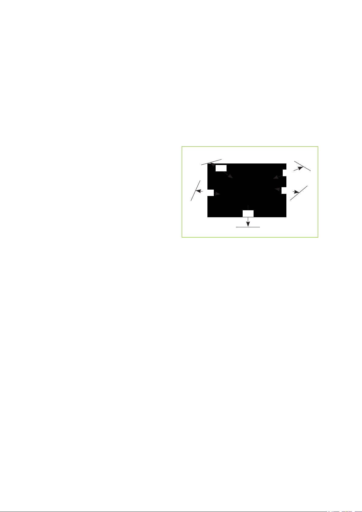
Minimum clearances
Observe the minimum clearances to allow access
for maintenance and repair work and facilitate
optimum air distribution.
Fig. 25: Minimum clearances MXD 262-522 (all
measurements in mm)
Installation materials
The indoor unit is fastened using a wall brace and
4 bolts (provided by the customer). In order to
complete the installation, use the supplied installation material. Appropriate dowels, trapezoidal
sheet metal supports, steel profiles, fixing clips for
refrigerant and condensation pipes (as well as
laying ducts) and connection fittings for condensation pipes must also be provided.
22
Page 23
522
522
1
1
A
B
A
6
Unit installation
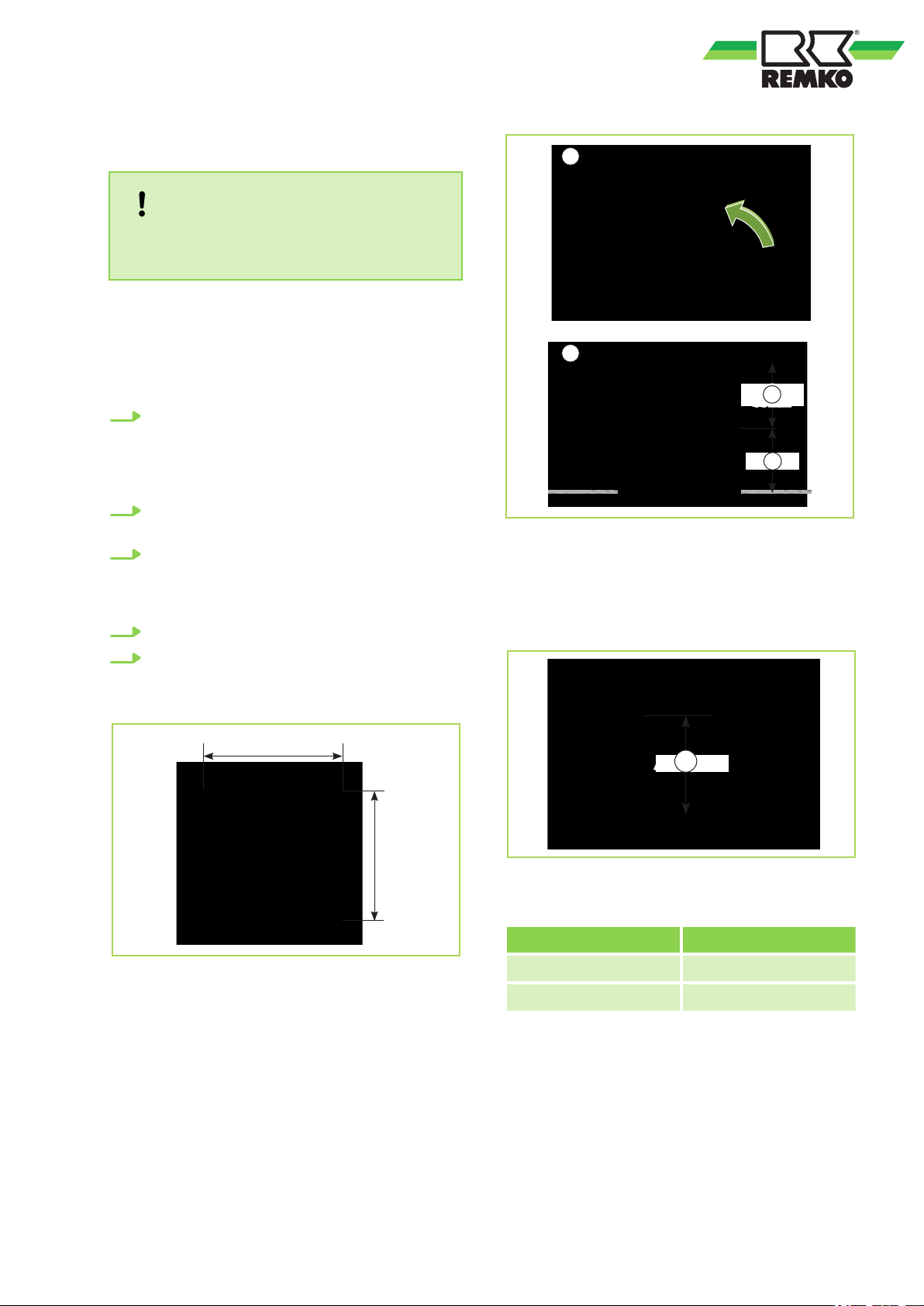
The unit is mounted on four threaded rods with the
cover face down. Take into account the ceiling grid
and any other installations.
1. Use the dimensions of the ceiling cassette to
2. Fit the indoor unit onto the threaded rods and
3. Ensure a clearance of 35 mm from the
4. Check that the unit is level.
5. The final task is to tighten the counternuts
Installation
NOTICE!
Installation should only be performed by
authorised specialists.
mark the fixing points for the threaded rods
on structural parts approved to support the
static load, and above the suspended ceiling.
(Fig. 26).
use the lower nuts to level the unit (Fig. 27
ceiling. Connect the refrigerant pipes, electrical cables and condensation pipe to the
indoor unit as described below.
and attach the cover.
).
Fig. 27: Hooking in the unit (MXD 202-522)
1: Structural component
A: Minimum 35 mm
B: 265 mm
Fig. 28: Fasten the unit
A: Distance A
Fig. 26: Unit attachment (MXD 202-522)
23
MXD 262-522
Distance A 70 mm
Suspension 545 mm x 525 mm
Page 24
2
1
2
REMKO MXD
Connecting the refrigerant lines
Bby customer on-site connecting the refrigerant lines are at a corner of the unit within the false ceiling. It may
be necessary to fit a reducing or extending adapter to the indoor units. These fittings are included with the
indoor unit as an accessory kit. Once installed, the connections should be sealed to prevent vapour diffusion.
Performence Indoor unit Refrig-
erant pipe
Indoor unit Con-
necting
EL SL SL EL SL SL EL SL
2,0 kW 1/4" 3/8" - 1/4" 3/8" - 1/4" 3/8"
2,6 kW 1/4" 3/8" - 1/4" 3/8" - 1/4" 3/8"
3,5 kW 1/4" 3/8" - 1/4" 3/8" - 1/4" 3/8"
5,2 kW 1/4" 3/8" Erw. 3/8" AT -> 1/2" IT 1/4" 1/2" - 1/4" 1/2"
Note: SL = Suction pipe (large pipe), EL = injection pipe (small pipe)
Adjacent room and fresh air connection
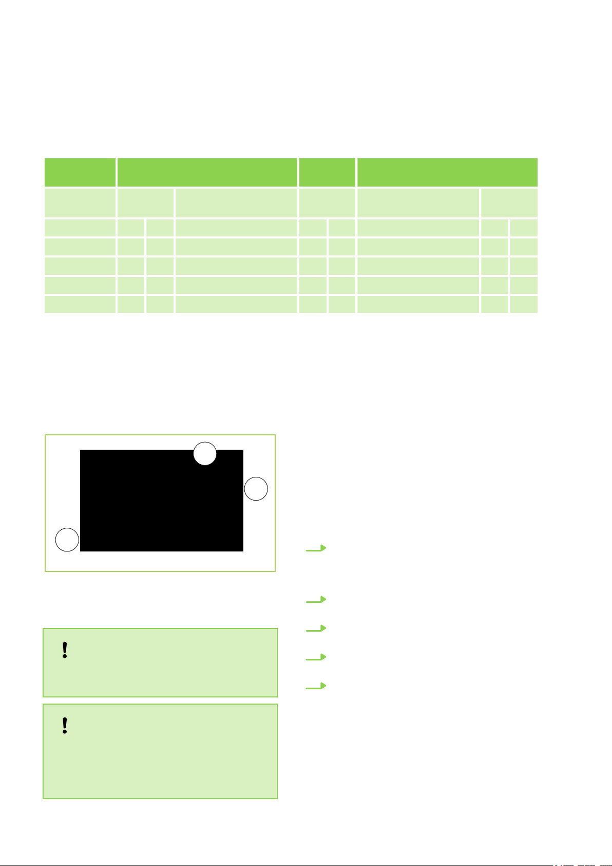
The indoor unit is designed to cool an adjacent
second room and, independently of this, to suction
in fresh air.
Reducing / extending Refrig-
erant pipe
Indoor unit MXD 202-522
Reducing / extending Con-
necting
Fig. 29: Adjacent room and fresh air connection
1: Fresh air connection
2: Adjacent room connection
NOTICE!
Only one adjacent room connection and one
fresh air connection may be used!
NOTICE!
The unit is factory filled with dry nitrogen for
leak testing purposes. The pressurised
nitrogen is released when the union nuts are
undone.
Installation instructions
To install the fresh air connection and the connection for the adjacent room, proceed as follows:
1. Remember that directly behind the insulation
to be removed are the plate fins of the heatexchanger and that these may by no means
be damaged (Fig. 30
2. Carefully remove the insulation behind the
opening. (Fig. 31).
3. Break through the corresponding openings
(Fig. 32).
4. Keep the vent pipe as short as possible and
lay it with as few bends as necessary.
5. Keep in mind that the flanged collar, screws,
flexible/folded spiral-seam pipes and insulation materials must be provided by the customer. These parts can all be purchased
from your dealer. (Fig. 33).
).
24
Page 25
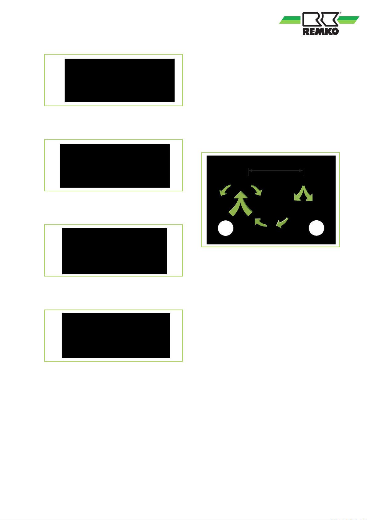
Fig. 30: Remove punching outs
max. 7 m
A
B
n There must be an opening created between
the two rooms that allows the air to circulate
between them.
n A maximum pipe length of 7 m may not be
exceeded (Fig. 34).
n To ensure that air is transported to the adja-
cent room, 1 or 2 of the 4 air outlets are to be
sealed on the indoor unit. To do this, use a
black strip with adhesive on one side which is
stuck to the opening(s) to be sealed. The strip
must be able to permanently withstand the
strain from the air pressure.
Fig. 31: Remove insulation
Fig. 32: Break through openings
Fig. 33: Mounting connecting piece
Fig. 34: Adjacent room connection
A: Main room
B: Adjacent room
Fresh air connection
As already described, it is possible to suction in
fresh air (outside air) in addition to the room air
with the indoor unit and regulate the temperature.
This is the preferred alternative in rooms where air
is used up quickly.
n Pay attention to local regulations for air treat-
ment.
n For the fresh air connection, a flanged collar
with a minimum diameter of 65 mm must be
mounting (Fig. 35).
Adjacent room connection
The indoor unit allows you to cool an adjacent
room via a duct system, e.g. in a suspended
ceiling. The following conditions must be met:
n Pay attention to local regulations for air treat-
ment.
n For the adjacent room connection, a flanged
collar with a minimum diameter of NW 150
must be mounting.
n The cooling capacity of the indoor unit must be
adequate for cooling both rooms.
25
Page 26
AB
1
1
REMKO MXD
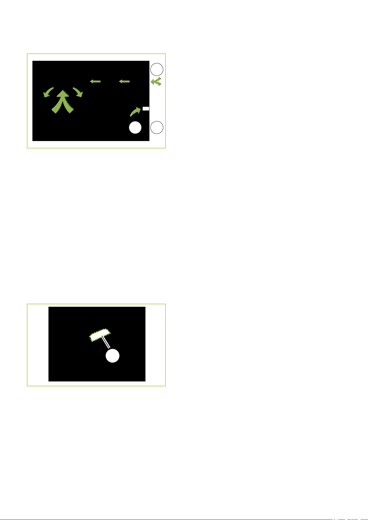
Fig. 35: Fresh air connection
1: Fresh air inlet
A: Outdoor
B: Indoor
n The quantity of fresh air may not exceed 10%
of the nominal circulating air volume; otherwise
it is possible that the unit will not work properly.
n To prevent rainwater from entering the unit, the
air may only be suctioned in by the fresh air
intake at a maximum speed of 2.5 m/s.
n To connect the fan, it is necessary for the cus-
tomer to install a separately fused electrical
installation.
In addition, in the following picture framed polystyrene partition the drip pan must be removed
with a knife. (Fig. 36).
Fig. 36: Fresh air inlet
1: Fresh air inlet
26
Page 27
A
C
B
D
16-20 mm
min. 2%
max.
500 mmWS
7
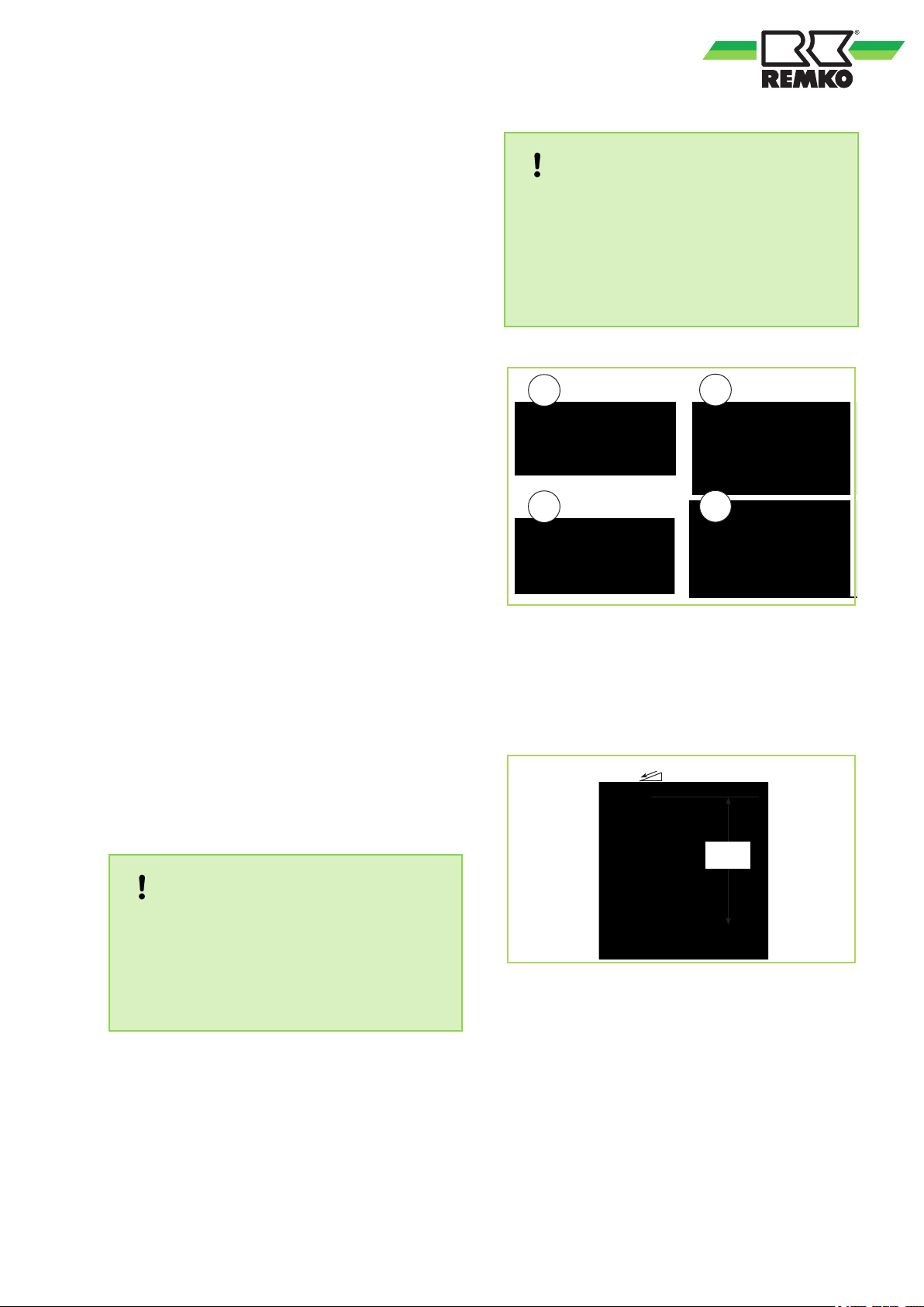
n The condensate tray should have an incline of
n IIf the level of the condensation pipe on the unit
n Guide the unit’s condensation pipe into the
n When operating the unit at outside tempera-
n Following installation, check that the conden-
Condensate draining
If the temperature falls below the dew point, condensation will form on the cooling fins during
cooling mode. A collection tray together with a condensation pump and float switch are fitted as
standard below the cooling fins. Should the float
switch trip a protective shutdown due to inadequate removal of the condensation, the pump will
switch on immediately and run on for approx. three
minutes.
Condensate connection and safe drainage
min. 2%. This is the responsibility of the customer. If necessary, fit vapour-diffusion-proof
insulation.
is above that of the outlet, route the pipe vertically upwards and then with a fall to the drain
drain pipe. If the condensation is being guided
to a drainage pipe, please install a siphon-like
hose guideway which acts as an odour seal.
The diameter of the condens connecting piece
is 25 mm.
tures below 4 °C, ensure the condensate
drainage is laid to protect it against frost. The
lower part of the housing and condensate tray
is also to be kept frost free in order to ensure
permanent draining of the condensate. If necessary, fit a pipe heater.
sate run off is unobstructed and ensure that the
line is durably leak tight.
NOTICE!
The maximum capacity of the condensate
pump is 500 mm WS. External influences, such
as air-side back pressure, contamination, or
wear may cause a reduction in performance.
To ensure safe operation function, we recommend a maximum conveyor height of 450 mm
should not be exceeded!
Fig. 37: Condensate connection - wrong!
A: Faraway riser
B: To large/small condensate pipe
C: No slope
D: No free outlet
Ensured discharge in the event of leakage
NOTICE!
Local regulations or environmental laws, for
example the German Water Resource Law
(WHG), can require suitable precautions to
protect against uncontrolled draining in case of
leakage to provide for safe disposal of
escaping refrigerator oil or hazardous media.
Fig. 38: Condensate connection - right!
27
Page 28
REMKO MXD
8
8.1
A protected mains supply cable is to be connected
to the outdoor unit and four-wire control line is to
be connected to the indoor unit respectively and
protect accordingly.
n We recommend to install a main / repair switch
n The terminal blocks for making the connections
n If a condensate pump is available as an acces-
Electrical wiring
General information
DANGER!
All electrical installation work is to be performed by specialist companies. Disconnect
the power supply when connecting the electrical terminals.
NOTICE!
The electrical connection for the units must be
made at a separate feedpoint with a residual
current device in accordance with local regulations and should be laid out by an electrician.
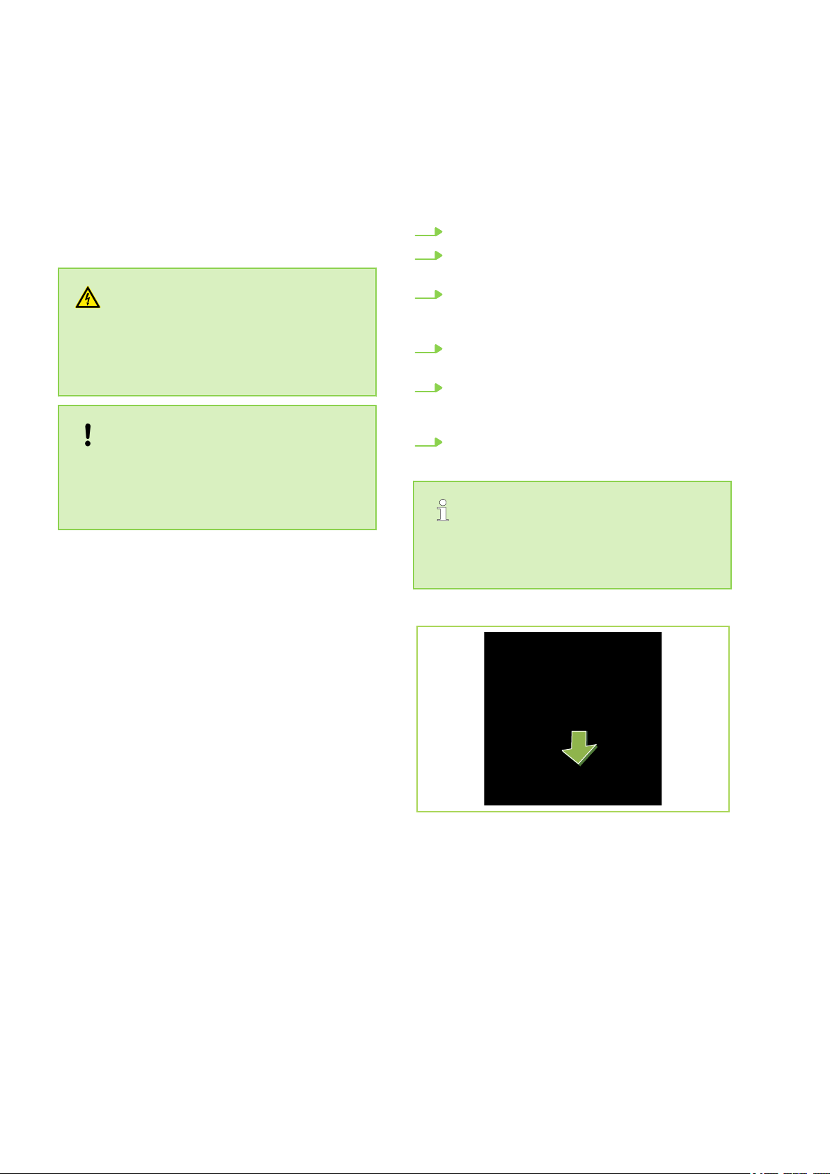
on the building near the indoor unit.
are located inside of the unit. After opening the
cover, they are reachable.
sory, when using a turn off switch of the pump
stop the power supply to the indoor unit.
8.2
Unit connection
Make the connection as follows:
1. Open the air inlet grill.
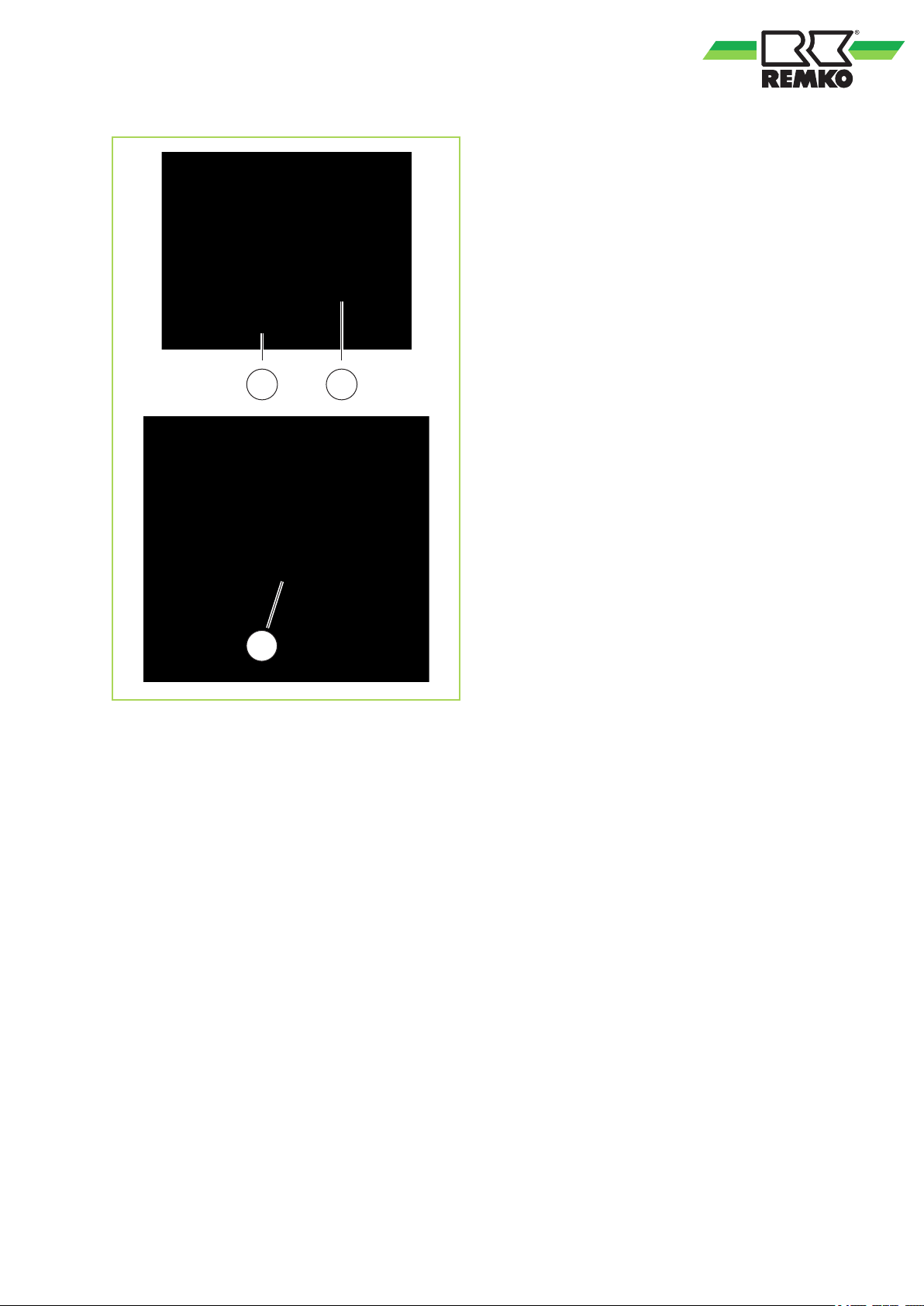
2. Remove the cover of the control box
(Fig. 40).
3. Guide the power-free cable through the edge
protection rings in the box and lock the cable
in the strain relief.
4. Then connect the cable according to the
wiring diagram.
5. Connect the electrical connector of the cover
with the corresponding counterparts of the
cassette. A confusion is not possible.
6. Re-assemble the unit.
Check all plugged and clamped terminals to
verify that they are seated correctly and make
permanent contact. Tighten as required.
Fig. 39: Accsess to the switch box
28
Page 29
2
1
3
Fig. 40: Unit connection
1: Entrance power supply
2: Dismantle the cover of the switch box
3: Connection control line from the outdoor unit
29
Page 30
230V/1~/50 Hz
L(A) N(A) S(A) L N
L(B)
N(B) S(B)
L(C) N(C) S(C)
L(D)
N(D) S(D)
L N S
L N S
L N S
L N S
A
1
B1 B2
B3 B4
2
2
REMKO MXD
8.3
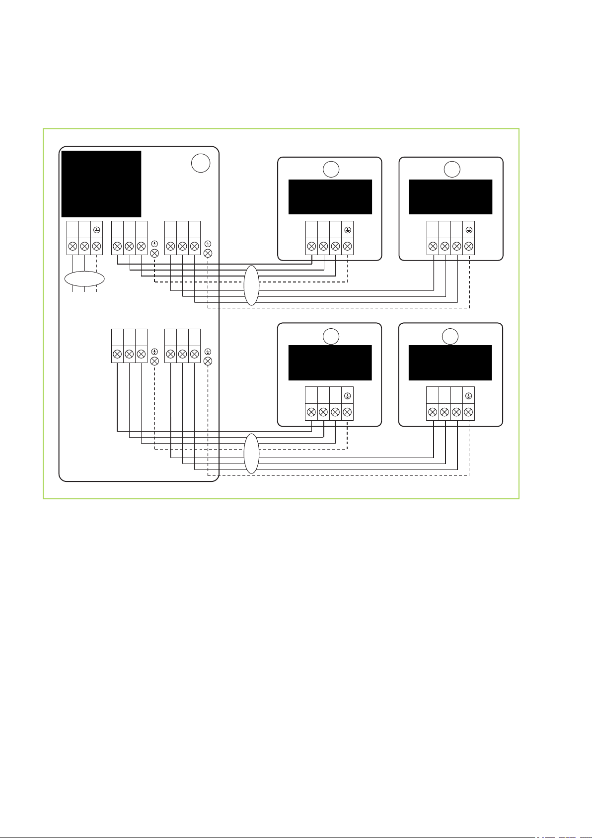
Electrical connection diagram
Connection MVT 601 DC-1051 DC
Fig. 41: Electrical connection diagram
A: Outdoor unit MVT 601 DC-1051 DC
B: Indoor units MXD 202-522
1: Power supply
2: Communication lines
30
Page 31
21
ON
1
2
ON
1
2
ON
1
2
ON
1
2
ON
1
2
ON
1
2
ON
1
2
ON
1
2
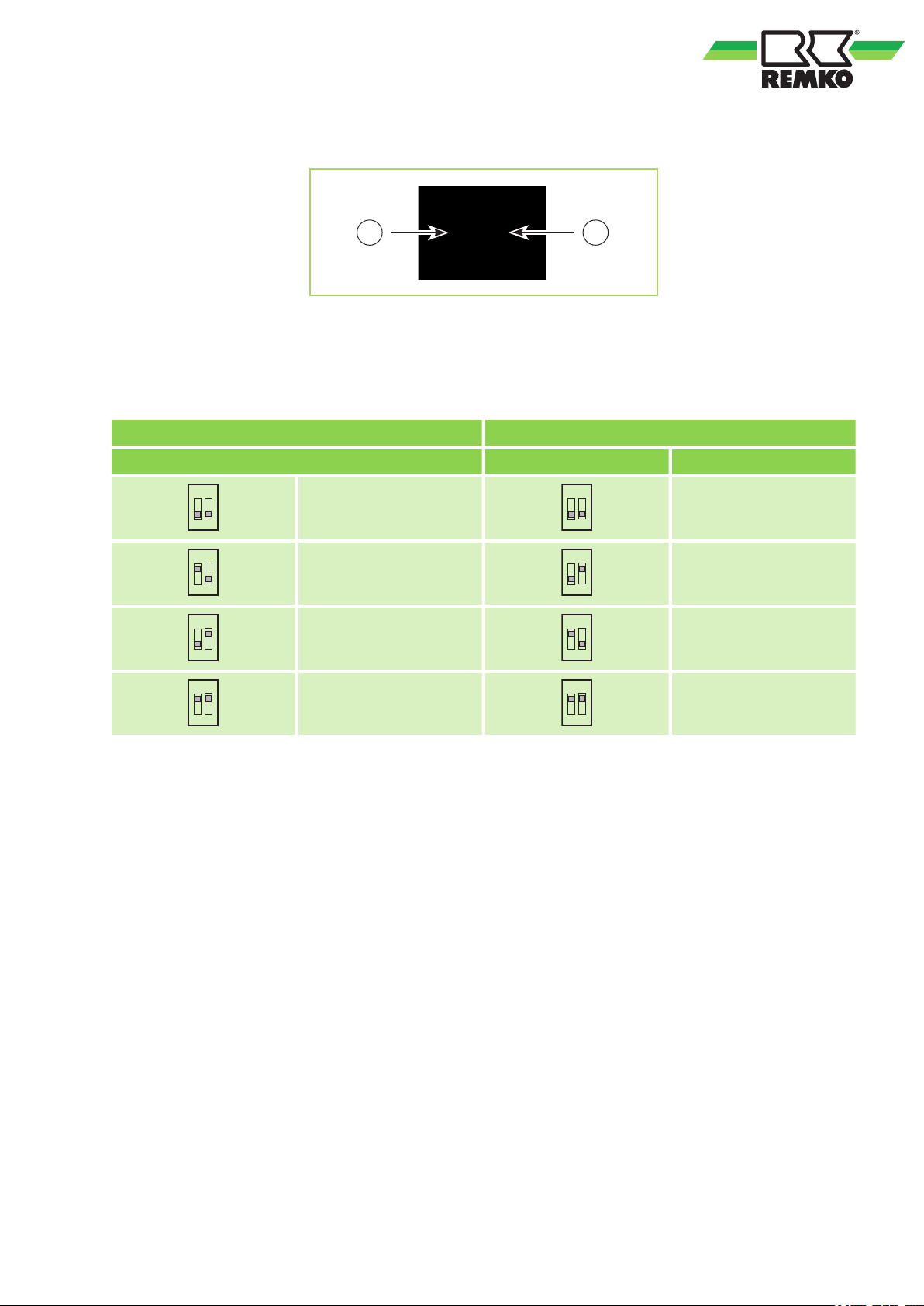
8.4
Choice of unit
Fig. 42: Choice of unit with DIP-switch
1: DIP-switch 1 (SW6)
2: DIP-switch 2 (SW7)
DIP-switch 1 (SW6) DIP-switch 2 (SW7)
Choice of temperature Choice of unit Unit
6 K
4 K
MXD 202
MXD 262
2 K
EEPROM-dependend
MXD 352
MXD 522
31
Page 32
CE-KFR20Q4/BP3TN1Y(hb)-A.D.11.NP2-1
202302141057
CN23
ON/OFF
CN33
ALARM
SW6 SW1 SW7 S1 S2
FUSE1
T5A/250VAC
CN9 CN40
CN17
CN14 SWING
CN10
CON-debug
CN5 WATER
CN6 T1 T2
CN7
CN12
HEAT
CN1
POWER
CN13
PUMP
P4 NEWFAN L
P5 NEWFAN N
P1 N
P6
CN15
2
1
4
3
5 6
7
8
9 A
10
11
SW2
12
REMKO MXD
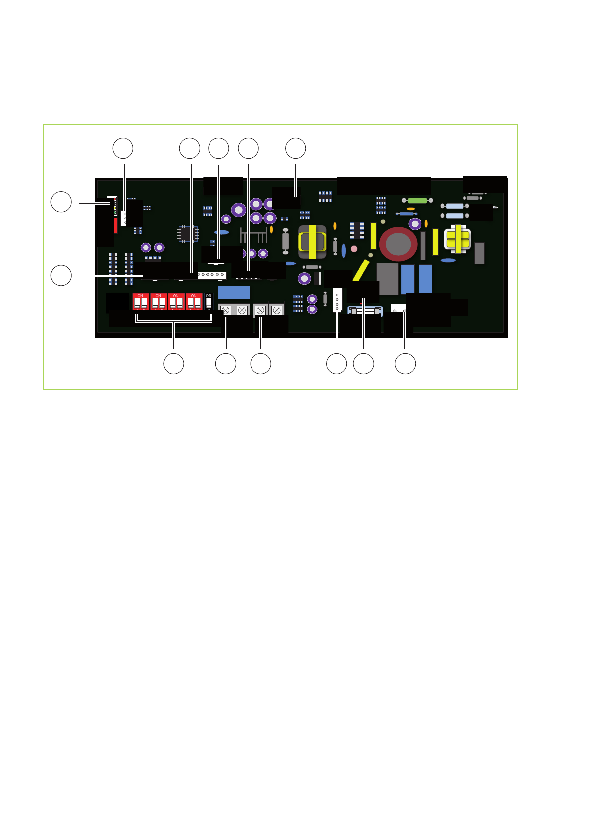
8.5
Electrical circuit diagram
MXD 202-352
Fig. 43: Electrical circuit diagram
A: Power supply control board
1: Swing motor
2: Connectivity cable remote control
3: MCC-bus
4: Connection display board
5: Liquide level switch condensate
6: Probe suction pipe, probe room temperature
7: External start/stop contact
8: DIP-switch
9: Alarm contact (optional)
10: External start/stop contact (optional)
11: Evaporator fan motor
12: Connection condensate pump
32
Page 33
MXD 522
CE-KFR20Q4/BP3TN1Y(hb)-A.D.11.NP2-1
202302141057
CN23
ON/OFF
CN33
ALARM
SW6 SW1 SW7 S1 S2
FUSE1
T5A/250VAC
CN9 CN40
CN17
CN14 SWING
CN10
CON-debug
CN5 WATER
CN6 T1 T2
CN7
CN12
HEAT
CN1
POWER
CN13
PUMP
P4 NEWFAN L
P5 NEWFAN N
P6
SW3
CN4 H M L
2
1
4
3
5
6
7
8 9 A10
11 12
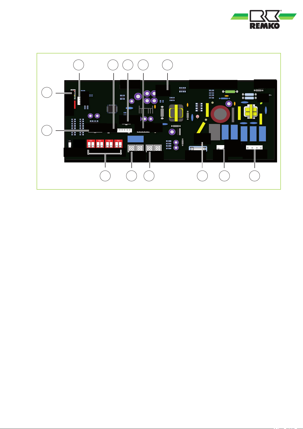
Fig. 44: Electrical circuit diagram
A: Power supply control board
1: Swing motor
2: Connectivity cable remote control
3: MCC-bus
4: Connection display board
5: Liquide level switch condensate
7: External start/stop contact
8: DIP-switch
9: Alarm contact (optional)
10: External start/stop contact (optional)
11: Connection condensate pump
12: Evaporator fan motor
6: Probe suction pipe, probe room temperature
33
Page 34
REMKO MXD
9
Functional test for cooling mode
1. Switch the supply voltage on.
2. Use the remote control to turn on the unit and
3. Measure and record all the required values in
4. Check the control system for the unit using
5. Check the correct function of the condensa-
Commissioning
NOTICE!
Commissioning should only be performed by
specially trained personnel and documented
after the certificate has been issued. Observe
the operating manuals for the indoor unit and
outdoor unit when commissioning the entire
system.
Check the DIP switch settings on the PCB, as
illustrated on chapter "Choice of unit". If necessary, set the DIP switches to the appropriate
indoor unit type.
select the cooling mode, maximum fan speed
and lowest nominal temperature.
the commissioning report and check the
safety functions.
the functions described in the chapter "Operation". Timer, temperature setting, fan
speeds and changing to air circulation or
dehumidifying mode.
tion line by pouring distilled water into the
condensation tray. A bottle with a spout is
recommended for pouring the water into the
condensation tray.
Functional test for heating mode
1. Switch the supply voltage on.
2. Use the remote control to switch on the unit
and select the heating mode, maximum fan
speed and highest nominal temperature.
3. Measure and record all the required values in
the commissioning report and check the
safety functions.
4. Measure the air intake temperature of the
ceiling mounted cassette and the room temperature approx. 1.5 m above the floor. In the
event of deviation, correct any temperature
difference by means of the DIP switch SW1
(s.
Ä
on page 31).
5. Check the control system for the unit using
the functions described in the chapter "Operation". Timer, temperature setting, fan
speeds.
Final tasks
n Reassemble all disassembled parts.
n Familiarise the operator with the system.
NOTICE!
Check that the shut-off valves and valve caps
are tight after carrying out any work on the
cooling cycle. Use appropriate sealant products as necessary.
34
Page 35
10
Temporary shut-down
1. Allow the indoor unit to run for 2 to 3 hours in
2. Shut down the system using the remote con-
3. Switch off the voltage supply to the unit.
4. Check the unit for visible signs of damage
Permanent shut-down
Ensure that equipment and components are disposed of in accordance with the applicable regulations, e.g. through authorised disposal and recycling specialists or at collection points.
REMKO GmbH & Co. KG or your contractual
partner will be pleased to provide a list of certified
firms near you.
Shut-down
air circulation mode or in cooling mode at the
maximum temperature setting in order to
remove any residual moisture from the unit.
trol.
and clean it as described in the chapter
"Care and maintenance"
35
Page 36
REMKO MXD
11
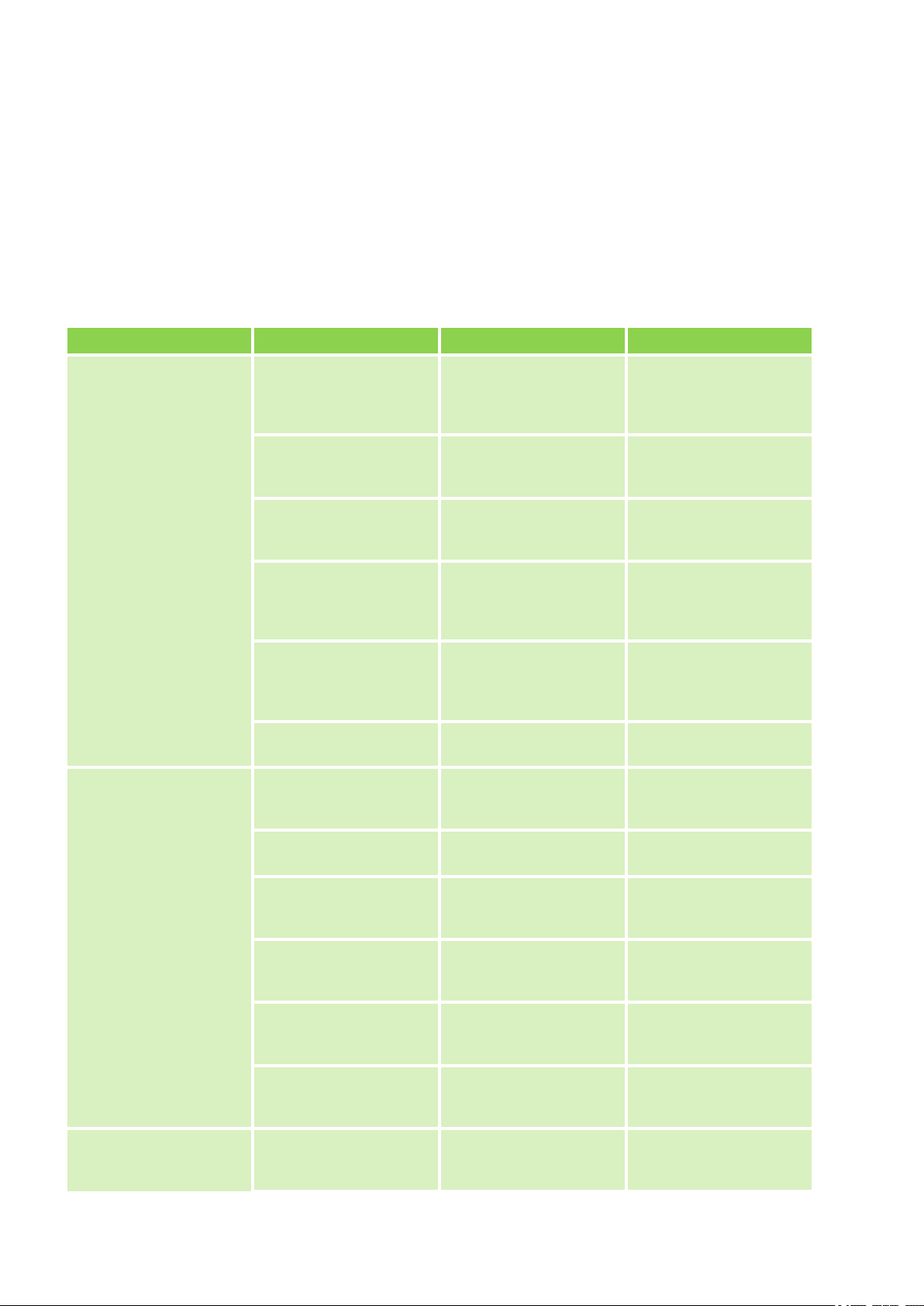
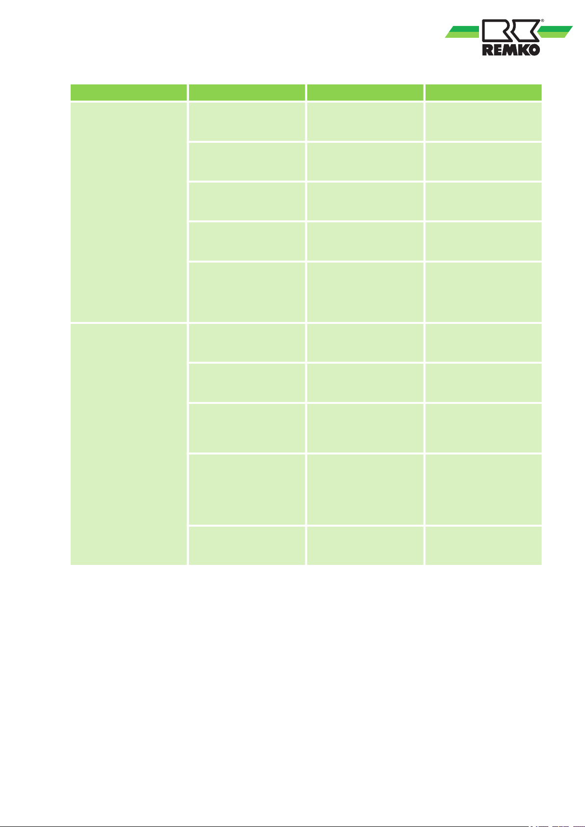
The equipment and components are manufactured using state-of-the-art production methods and tested several times to verify their correct function. If malfunctions should occur, please check the functions as detailed
in the list below. For installations with an indoor unit and outdoor unit, refer to the chapter "Troubleshooting
and customer service" in both manuals. Please inform your dealer if the unit is still not working correctly after
all the functional checks have been performed!
Malfunctions
Fault Possible cause Checks Remedy
The unit does not start or
switches it self off
Troubleshooting and customer service
Power outage, undervoltage, defective mains
fuse / main switch in off
position
Damaged mains cable Are all other electrical
Wait time after switching
on is too short
Temperature outside
operating range.
Are all other electrical
installations functioning
correctly?
installations functioning
correctly?
Have approx. 5 minutes
elapsed since the
restart?
Are the fans in the indoor
unit and outdoor component working correctly?
Check voltage if necessary wait until turned on
again.
Repair by a specialist
Schedule longer waiting
periods
Take into account the
temperature range for
the indoor unit and outdoor component
The unit does not
respond to the remote
control
Electrical surges caused
by thunderstorms
Fault in external condensation pump
Transmission distance
too far / receiver affected
by interference
Defective remote control Is the unit running in
Receiver or transmitter
unit exposed to excessive solar radiation
Electromagnetic fields
are interfering with transmission
Button in remote control
jammed / two buttons
pressed at same time
Batteries in remote control are flat
Have there been lightning strikes in the area
recently?
Did the pump shut down
due to a fault?
Does the indoor unit
beep when pressing a
button?
manual mode?
Does it function correctly
in the shade?
Does it function when
switching off possible
sources of interference?
Does the “Send” symbol
appear on the display?
Have new batteries been
inserted? Is the display
incomplete?
Switch off the mains
breaker and switch it
back on. Have it checked
by a specialist
Check and if necessary
clean the pump
Reduce the distance to
less than 6 m or change
position
Replace the remote control
Place the receiver &
transmitter unit in the
shade
Signal is not transmitted
when interference
sources are operational
Release the button /
press only one button
Insert new batteries
The unit is running with
reduced or without
cooling / heating output
Filter is unclean / air
inlet / outlet blocked by
foreign objects
Have the filters been
cleaned?
Clean the filters
36
Page 37
Fault Possible cause Checks Remedy
Windows and doors
open. Heating/cooling
loads increased
Neither cooling nor
heating mode has been
set
Fins on outdoor component blocked by foreign
objects
Leaking refrigerant circuit Are there signs of frost
Outdoor component icedupCheck outdoor compo-
Drainage pipe on collection container clogged /
damaged
Faulty external condensation pump or float
Have there been any
structural / usage-related
changes?
Does the cooling symbol
appear on the display?
Is the fan on the outdoor
component running? Are
the fins unobstructed?
on the fins of the indoor
unit?
nent. Has the cassette
sensor on the outdoor
component been correctly positioned?
Can the condensation
drain off without any
obstruction?
Is the collection tray full
of water and the pump
not running?
Close windows and
doors / install additional
units
Correct the settings for
the unit
Check the fan or winter
controller, reduce the air
resistance
Repair by specialist
De-ice and fit the sensor
at the point where the
most ice forms
Clean the drainage pipe
and collection container
Call out a specialist to
replace the pump
Condensation discharge
on unit
Condensation has not
drained away and has
collected in the condensation line
Condensation does not
drain off
Float is stuck or jammed
due to excessive dirt
Is there a steady fall on
the condensation pipe?
Check there is no
blockage in the pipe
Are the condensation
lines unblocked and laid
on a slope? Are the condensation pump and float
switch functioning correctly?
Are the LEDs on the
receiver unit of the
indoor unit flashing?
Ensure there is a fall
when laying the condensation pipe and clean the
pipe
The condensation line
must have a fall. If necessary, clean the pipe.
A faulty condensation
pump and float switch
should be replaced
Should be cleaned by
specialist firm
37
Page 38
REMKO MXD
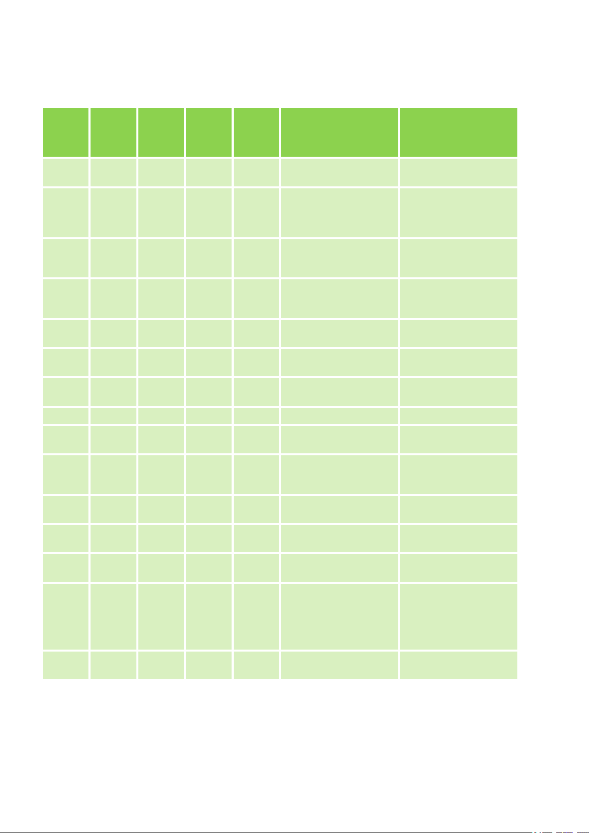
Fault indication by flashing code
LED
OPERA-
TION
(green)
on on
on
on on
flashes
LED
TIMER
(orange)
on
flashes
LED
DEF/
FAN
(red)
Normal operation, no
Normal operation, no
flashes
LED
ALARM
(red)
OU Dis-
play
-
-
E7
Cause Required action
Normal operation, no
faults: heating mode
Normal operation, no
faults: cooling-, recirculating air or automatic
mode
faults: On timer programmed
faults: Off timer programmed
Probe recirculating air
defective/actuated
Probe vaporizer defective/actuated
Communication error
between PCBs OU & IU
Check resistance on
sensor
Check resistance on
sensor
Check electrical connection leads
-
-
-
-
flashes flashes E0 EEPROM error Check EEPROM
flashes on -
flashes -
flashes on E4
flashes on on E5
flashes on P0
flashes on on -
flashes flashes flashes P3
For further fault diagnosis and troubleshooting s. corresponding user manual outer part.
Shutdown inverter
module
Liquid level switch condensate pump defective/
actuated
Probe outdoor temperature OU actuated
Surge voltage on outdoor
unit
Overtemperature compressor
Mode conflict:
Set unit with fault display
on refrigerators and
other appliances to
heating mode
Power consumption on
OU too high
Contact specialist dealer
Check resistance and
temperature on sensor
Check power supply
Allow to cool compressor
Priority heating: program
all unitss on cooling
mode / de-energize
Check power consumption
-
38
Page 39
12
Regular care and observation of some basic points
will ensure trouble-free operation and a long
service life.
Prior to performing any work, ensure the equipment is disconnected from the voltage supply
and secured to prevent accidental switch-on!
Care
n Ensure the unit is protected against dirt, mould
and other deposits.
n Clean the unit using a damp cloth. Do not use
any caustic, abrasive or solvent-based
cleaning products. Do not use a jet of water.
n Clean the fins on the unit prior to long shut-
down periods.
Care and maintenance
DANGER!
Maintenance
n We recommend a maintenance contract with
annual maintenance interval with an appropriate specialist company.
This enables you to ensure the operational reliability of the plant at all times!
Cleaning the cover of the indoor unit
1. Disconnect the supply voltage to the equip-
ment.
2. Open and fold down the air inlet guard on the
cover. The filter is held in place by the flaps
screwed in at the side of the guard (Page 16,
Fig. 1). (Fig. 45 ).
3. Clean the guard and cover using a soft,
damp cloth.
4. Switch the supply voltage back on.
Type of task
Checks/maintenance/inspection
General
Check voltage and current
Check function of compressor/fans
Dirt on condenser/evaporator
Check refrigerant fill quantity
Check condensate drainage
Check insulation
Check moving parts
Sealing test for cooling cycle
1)
See note
NOTICE!
Statutory regulations require an annual leak test for the cooling cycle dependant on the refrigerant quantity. Inspection and documentation of the work performed is to be carried out by specialist technicians.
Commis-
sioning
l
l
l
l l
l
l
l
l
l
Monthly Every 6
months
l
l
Yearly
l
l
l
l
l
1)
l
39
Page 40
REMKO MXD
Air filter for indoor unit
Clean the air filter at intervals of no more than two
weeks. Reduce this interval if the air is especially
dirty.
Cleaning the filter
1. Disconnect the supply voltage to the equip-
ment.
2. Open and fold down the air inlet guard on the
cover. The filter is held in place by the flaps
screwed in at the side of the guard. (Fig. 45).
3. Tilt the filter to lift it out (Fig. 45).
4. Clean the filter using a normal vacuum
cleaner (Fig. 46). To do so, turn the dirty side
upward.
5. Dirt can also be removed by carefully
cleaning with lukewarm water and mild
cleaning agents. To do so, turn the dirty side
downward (Fig. 47
6. When using water, allow the filter dry out
properly in air before replacing it in the unit.
7. Carefully insert the filter. Make sure it is
seated correctly.
8. Close the cover as described above but in
reverse order.
9. Switch the supply voltage back on.
10. Switch the unit on again.
).
Fig. 46: Cleaning using a vacuum cleaner
Fig. 47: Cleaning with lukewarm water
Cleaning the condensation pump
The indoor unit includes a built-in condensation
pump, for pumping the condensation to a drain at
a higher level.
The pump is more or less maintenance free. The
condensation pipes should be checked for dirt at
regular intervals. Clean them as required.
If an external pump is also used, observe the
maintenance and care instructions given in the
separate operating manual.
Fig. 45: Pull out the filter
40
Page 41
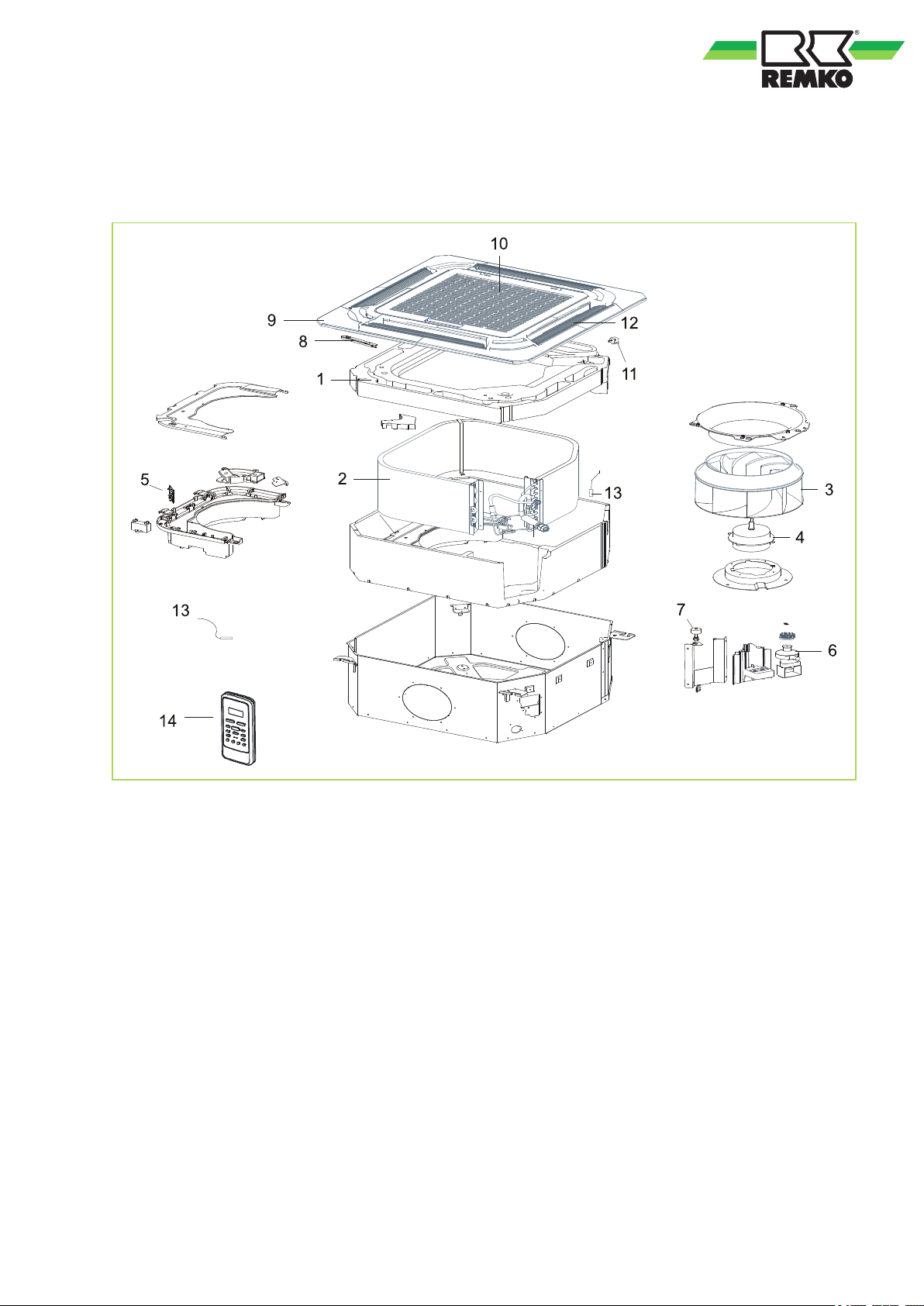
13
13.1
Exploded view of the unit and spare parts list
Exploded view
Fig. 48: Exploded view MXD 202-522
We reserve the right to modify the dimensions and structural design as part of the ongoing technical-development process.
41
Page 42
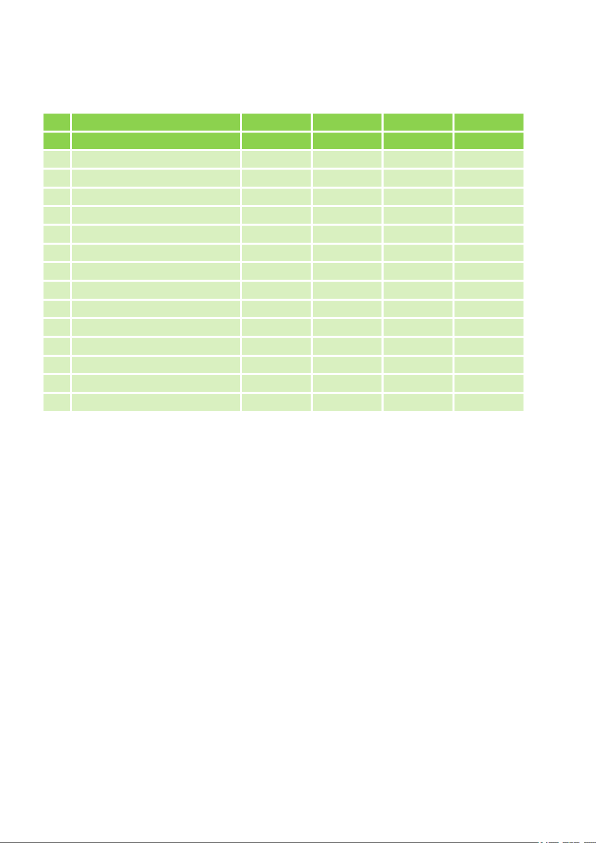
REMKO MXD
13.2
No. Designation MXD 202 MXD 262 MXD 352 MXD 522
1 Condensation tray 1111053 1111053 1111053 1111053
2 Vaporiser 1111076 1111077 1111078 1112509
3 Fan wheel 1111056 1111056 1111056 1111056
4 Vaporiser fan motor 1112500 1112500 1112500 1112510
5 Control board 1112501 1112501 1112508 1112511
6 Condensation pump, cpl. 1111062 1111062 1111062 1111062
7 Condensation float switch 1112502 1112502 1112502 1112502
8 Display board 1111064 1111064 1111064 1111064
9 Cover cpl. 1112503 1112503 1112503 1112503
10 Air filter 1112504 1112504 1112504 1112504
11 Fin motor 1111068 1111068 1111068 1111068
12 Outlet fins, set of 4 1112505 1112505 1112505 1112505
Spare parts list
From series: 1324... 1325... 1326... 1327...
13 Set of temperature probe 1112506 1112506 1112506 1112506
14 IR remote control 1112507 1112507 1112507 1112507
When ordering spare parts, please state the computerised part no., device number and device type (see
identification plate)!
42
Page 43

14
A
Adjacent room and fresh air connection............ 24
Adjacent room connection........................... 24, 25
C
Cable remote control.......................................... 21
Care and maintenance....................................... 39
Choice of temperature....................................... 31
Choice of unit..................................................... 31
Cleaning
Combinations..................................................... 10
Condensate draining ......................................... 27
Connecting the refrigerant lines......................... 24
Customer service .............................................. 36
D
DIP-Schalter....................................................... 31
Display on the indoor unit ................................. 13
Disposal of equipment......................................... 6
E
Electrical circuit diagram.............................. 32, 33
Electrical connection.......................................... 28
Electrical connection diagram............................ 30
Ensured discharge in the event of leakage ....... 27
Environmental protection..................................... 6
Exploded view ................................................... 41
F
Fault indication by flashing code........................ 38
Flashing code..................................................... 38
Fresh air connection.................................... 24, 25
Fresh air inlet..................................................... 26
Functional test
G
Greenhouse gas according to Kyoto protocol...... 8
I
Infrared remote control ...................................... 12
Installation instructions....................................... 24
Installation location, selection............................ 22
Installation materials.......................................... 22
Index
Air filter for indoor unit .................................. 40
Condensation pump ..................................... 40
Cover of the indoor unit
Cooling mode................................................ 34
Heating mode................................................ 34
................................. 39
Intended use........................................................ 5
K
Keys on the remote control................................ 13
M
Maintenance...................................................... 39
Malfunctions
Checks.......................................................... 36
Possible cause.............................................. 36
Remedy......................................................... 36
Manual operation............................................... 12
Minimum clearances.......................................... 22
O
Order spare parts list......................................... 42
R
Refrigerant lines, connecting............................. 24
Remote control
keys............................................................... 13
S
Safety
Dangers of failure to observe the safety
notes............................................................... 4
General........................................................... 4
Identification of notes...................................... 4
Notes for inspection........................................ 5
Notes for installation....................................... 5
Notes for maintenance.................................... 5
Personnel qualifications.................................. 4
Safety-conscious working............................... 4
Safety notes for the operator.......................... 5
Unauthorised modification ............................. 5
Unauthorised replacement part manufacture.. 5
Selection of installation location......................... 22
Shut-down
Permanent.................................................... 35
Temporary..................................................... 35
Spare parts list................................................... 42
T
Troubleshooting and customer service ............. 36
U
Unit installation................................................... 23
W
Warranty.............................................................. 5
43
Page 44

REMKO MXD
44
Page 45

45
Page 46

REMKO MXD
46
Page 47

Page 48
Consulting
Thanks to intensive training,
our consultants are always
completely up-to-date in terms
of technical knowledge. This has
given us the reputation of being
more than just an excellent,
reliable supplier:
REMKO, a partner
helping you find solutions to
your problems.
Distribution
REMKO offers not just a well
established sales network both
nationally and internationally, but
also has exceptionally highlyqualified sales specialists.
REMKO field staff are more than
just sales representatives: above
all, they must act as advisers to
our customers in air conditioning
and heating technology.
SFlbCustomer Service
Our equipment operates
precisely and reliably. However,
in the event of a fault, REMKO
customer service is quickly at
the scene. Our comprehensive
network of experienced dealers
always guarantees quick and
reliable service.
REMKO INTERNATIONAL
… and also right in your neighbourhood!
Make use of our experience and advice
We reserve the right to make technical changes, and provide no guarantee as to the accuracy of this data!
REMKO GmbH & Co. KG
Air conditioning and heating technology
Im Seelenkamp 12 D-32791 Lage
Postfach 1827 D-32777 Lage
Telephone +49 52 32 606-0
Telefax +49 5232 6 06-260
E-mail [email protected]
Website www.remko.de
 Loading...