


 Loading...
Transducers for Fishfinders
Owner’s
Handbook
Document number: 81196_2
Date: August 2002
Transducers for Fishfinders |
iii |
Transducers for Fishfinders
Owners Handbook
August 2002
Intended Use
The transducer units detailed in this handbook are used in conjunction with Raymarine fishfinders and are intended for recreational marine depth, speed, and/or temperature measurement purposes.
Safety Notice
This equipment must be installed and operated in accordance with the instructions contained in this manual. Failure to do so can result in personal injury and/or navigational inaccuracies.
Raymarine products are supported by a network of Authorized Service Representatives. For information on Raymarine products and services, contact either of the following:
United StatesRaymarine, Inc. 22 Cotton Road, Unit D Nashua, NH 03063-4219 USA
Telephone 603-881-5200 Fax 603-864-4756 www.raymarine.com
EuropeRaymarine Ltd
Anchorage Park
Portsmouth
Hampshire PO3 5TD
England
Telephone +44 (0)23 9269 3611
Fax +44 (0)23 9269 4642
www.raymarine.com
© Raymarine, Inc. 2002
iv |
Transducers for Fishfinders |
Preface
This handbook describes the transducers that are required for use with Raymarine fishfinders. A list of currently available fishfinder transducers appears on page 4.
The handbook contains very important information on the installation and operation of your new equipment. In order to obtain the best results in operation and performance, please read this handbook thoroughly.
Raymarine’s Product Support representatives or your local dealer will be available to answer any questions you may have.
The technical and graphical information contained in this handbook, to the best of our knowledge, was correct as it went to press. However, the Raymarine policy of continuous improvement and updating may change product specifications without prior notice. As a result, unavoidable differences between the product and handbook may occur from time to time, for which liability cannot be accepted by Raymarine.
Raymarine is a registered trademark of Raymarine Limited. SeaTalk is a registered trademark of Raymarine Limited. hsb2 is a trademark of Raymarine Limited.
Warranty
Your transducer ownership warranty is registered when you fill out the warranty registration card included with your Raymarine Fishfinder Owner’s Handbook. It is very important that you complete the owner information and return the card to the factory in order to receive full warranty benefits.
EMC Conformance
All Raymarine equipment and accessories are designed to the best industry standards for use in the leisure marine environment.
The design and manufacture of Raymarine equipment and accessories conform to the appropriate Electromagnetic Compatibility (EMC) standards, but correct installation is required to ensure that performance is not compromised.
Contents |
|
|
v |
Contents |
|
|
|
Chapter 1: |
Overview ............................................................................... |
1 |
|
|
1.1 |
Introduction ....................................................................... |
1 |
|
|
General .............................................................................. |
1 |
|
|
EMC Installation Guidelines ............................................ |
2 |
|
1.2 |
The Fishfinder System ...................................................... |
3 |
|
|
Selecting the Correct Type of Transducer ......................... |
4 |
|
|
Planning the Installation ................................................... |
5 |
|
1.3 |
Unpacking and Inspecting the Components ..................... |
6 |
|
1.4 |
Selecting the Equipment Location .................................... |
6 |
|
|
Transducer Mounting Location ........................................ |
6 |
|
|
Transom Mount Transducer .............................................. |
7 |
|
1.5 |
Cable Runs ...................................................................... |
12 |
|
|
Transducer Cable ............................................................ |
12 |
Chapter 2: |
Installation .......................................................................... |
15 |
|
|
2.1 |
Installing the Transom Mount Transducer ...................... |
15 |
|
|
Preparation ...................................................................... |
15 |
|
|
Installation ...................................................................... |
16 |
|
2.2 |
Installing the Thru-hull Transducer ................................ |
17 |
|
|
Tools and Material Needed ............................................. |
17 |
|
|
Preparation ...................................................................... |
17 |
|
|
Installation ...................................................................... |
22 |
|
|
Installation in a Cored Fiberglass Hull ............................ |
29 |
|
|
Check for Leaks .............................................................. |
30 |
|
2.3 |
Installing the In-hull Transducer ..................................... |
31 |
|
|
Tools and Material Needed ............................................. |
31 |
|
|
Testing the Selected Mounting Location ........................ |
31 |
|
|
Installation ...................................................................... |
34 |
|
|
Installation in a Cored Fiberglass Hull ............................ |
37 |
|
2.4 |
Transducer Cable Connections ....................................... |
39 |
Chapter 3: |
Maintenance ....................................................................... |
43 |
|
|
|
Cleaning Instructions ...................................................... |
43 |
|
|
Servicing and Safety ....................................................... |
43 |
|
|
Problem Solving ............................................................. |
44 |
|
|
Common Problems and Their Solutions ......................... |
44 |
|
|
How to Contact Raymarine ............................................. |
45 |
|
|
Worldwide Support ......................................................... |
47 |
|
Index .................................................................................... |
49 |
|
vi |
Transducers for Fishfinders |
Chapter 1: Overview |
1 |
Chapter 1: Overview
1.1 Introduction
This handbook provides instructions to assist you in the installation and set up of the various transducers for Raymarine fishfinders. See Table 1-1 on page 4 for a list of the different sensor, material and mounting types available.
General
Raymarine fishfinders require a transducer, either thru-hull, in-hull, or transom-mount.
Transducers can measure water depth, temperature, distance traveled, and/or speed. It is important to position your transducer correctly, as described in Section 1.4, Selecting the Equipment Location.
Note: If speed and temperature are being input via SeaTalk, these values are displayed instead of the speed and temperature inputs from the transducer.
This handbook is divided into three chapters as follows:
Chapter One provides an overview of the transducer installation. It includes sections on Unpacking and Inspecting the Components, Selecting the Transducer Site and a description of the Cable Runs.
Chapter Two provides detailed instructions on how to mount and connect each type of transducer.
Chapter Three provides information on maintenance and what to do if you have problems.
2 |
Transducers for Fishfinders |
EMC Installation Guidelines
All Raymarine equipment and accessories are designed to the best industry standards for use in the leisure marine environment.
Their design and manufacture conforms to the appropriate Electromagnetic Compatibility (EMC) standards, but correct installation is required to ensure that performance is not compromised. Although every effort has been taken to ensure that they will perform under all conditions, it is important to understand what factors could affect the operation of the product.
The guidelines given here describe the conditions for optimum EMC performance, but it is recognized that it may not be possible to meet all of these conditions in all situations. To ensure the best possible conditions for EMC performance within the constraints imposed by any location, always ensure the maximum separation possible between different items of electrical equipment.
For optimum EMC performance, it is recommended that wherever possible:
•Raymarine equipment and cables connected to it are:
•At least 1 m (3 ft) from any equipment transmitting or cables carrying radio signals, e.g., VHF radios, cables and antennas. In the case of SSB radios, the distance should be increased to 2 m (7 ft).
•More than 2 m (7 ft) from the path of a radar beam. A radar beam can normally be assumed to spread 20 degrees above and below the radiating element.
•The equipment is supplied from a separate battery from that used for engine start. Voltage drops below 10 V (20 V for 10 kW open array scanners) in the power supply to our products, and starter motor transients, can cause the equipment to reset. This will not damage the equipment, but may cause the loss of some information and may change the operating mode.
•Raymarine specified cables are used at all times. Cutting and rejoining these cables can compromise EMC performance and so must be avoided unless doing so is detailed in the documentation.
•If a suppression ferrite is attached to a cable, this ferrite should not be removed. If the ferrite needs to be removed during installation it must be reassembled in the same position.
Chapter 1: Overview |
3 |
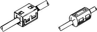
The following illustration shows a typical range of suppression ferrites fitted to Raymarine equipment.
D3548-3
Connections to Other Equipment
If your Raymarine equipment is to be connected to other equipment using a cable not supplied by Raymarine, a suppression ferrite MUST always be attached to the cable near to the Raymarine unit.
1.2 The Fishfinder System
Transducers enable fishfinders to display depth, water temperature and/or speed, depending on the type of transducer(s) installed.
Before you start the installation, check that you have the correct transducer for your application, as described below in Selecting the Correct Type of Transducer.

4 Transducers for Fishfinders
Selecting the Correct Type of Transducer
Raymarine Fishfinders can be used with any of the following transducers:
Table 1-1: Transducer Types
Part No. |
Sensor |
Material |
Mounting |
Max. |
Type |
Method |
Power |
||
|
|
|
|
|
E66008 |
Depth |
Plastic |
In-Hull |
600 W |
|
|
|
|
|
E66013 |
Depth |
Plastic |
Thru-Hull |
600 W |
|
|
|
|
|
E66014 |
Depth |
Bronze |
Thru-Hull |
600 W |
|
|
|
|
|
E66015 |
Depth |
Stainless |
Thru-Hull |
600 W |
|
|
steel |
|
|
|
|
|
|
|
E66018 |
Speed, Temp |
Bronze |
Thru-Hull |
600 W |
|
|
|
|
|
E66019 |
Speed, Temp |
Plastic |
Transom |
600 W |
|
|
|
|
|
E66020 1 |
Depth, |
Bronze |
Thru-Hull |
600 W |
|
Speed, Temp |
|
|
|
|
|
|
|
|
E66024 |
Depth, Temp |
Bronze |
Thru-Hull(high |
600 W or |
|
|
|
performance) |
1000 W |
|
|
|
|
|
E66029 1 |
Depth, |
Bronze |
Thru-Hull |
600 W |
|
Speed, Temp |
|
(long stem) |
|
|
|
|
|
|
E66030 |
Speed, Temp |
Plastic |
Thru-Hull |
600 W |
|
|
|
|
|
E66033 |
Depth, Temp |
Bronze |
Thru-Hull |
600 W or |
|
|
|
|
1000 W |
|
|
|
|
|
E66035 |
Depth, Temp |
Bronze |
Thru-Hull |
600W |
|
|
|
|
|
E66038 |
Depth, |
Plastic |
Transom |
600W |
|
Speed, Temp |
|
|
|
|
|
|
|
|
E66043 1 |
Depth, |
Stainless |
Thru-Hull |
600W |
|
Speed, Temp |
steel |
|
|
|
|
|
|
|
1 E66020, E66029 and E66043 thru-hull transducers must be installed with a highspeed fairing.
Note: This information was current as of the date this handbook was printed. New transducer models are constantly becoming available. Check with your dealer for the most current list.
Chapter 1: Overview |
5 |
WARNING:
If the E66020, E66029 and E66043 thru-hull transducers are not carefully installed and fitted to the shape of the hull, the vessel may take on water. To ensure proper alignment and a secure fit, these transducer models MUST be installed with a fairing. In addition to improving fishfinder performance at all speeds, the fairing allows better fitting to the hull and dramatically increases the sealing surface.
Applications
Plastic housings are recommended for fiberglass or metal hulls.
Bronze housings are recommended for wood or fiberglass hulls.
•Installation of a bronze housing in a metal hull requires using of a fairing, available from your Raymarine dealer.
•Never install a metal housing in a vessel with a positive ground system.
Transom Mount Transducers are recommended for personal watercraft and powerboats with outboard, inboard-outboard and jet drives. They are NOT recommended for large or twin screw inboard boats.
•Adjusts to transom angles from 3° – 16°. For angles greater than 16°, a tapered plastic, wood or metal shim will be needed.
•Designed for operation from 5 –58 m.p.h. (4 – 50 knots).
Thru-Hull Transducers are recommended for boats with straightshaft inboard engines.
In-Hull transducers are recommended for fiberglass hulls, especially in high speed power boats and racing sailboats.
Planning the Installation
Before you install your system, plan the installation, considering:
•Location of the transducer and fishfinder, as described in
Section 1.4
•Cable Runs, including cables for an integrated system (to provide heading and position data, etc.), as described in Section 1.5.

6 |
Transducers for Fishfinders |
1.3 Unpacking and Inspecting the Components
Unpack your system carefully, to prevent damage to the equipment. Save the carton and packing, in case you need to return a unit for service.
Check that you have all the correct system components. These depend on your system package, as follows:
Table 1-2: Parts and Accessories
|
Part |
Supplied |
Option |
Item |
No. |
with: |
for: |
|
|
|
|
Transducer (see Table 1-1 on page 4) |
— |
— |
All |
|
|
|
|
Transducer cable, 10 ft (3 m) extension |
E66009 |
— |
All |
Transducer cable, 18 ft (5 m) extension |
E66010 |
— |
All |
Transducer Y Cable |
E66022 |
Speed/Temp |
All others |
|
|
Transducers |
|
|
|
|
|
High Speed Fairing |
E660231 |
— |
E66020, E66029 |
|
E660452 |
— |
E66043 |
|
E66025 |
— |
E66024 |
|
E66034 |
— |
E66033 |
|
E26017 |
— |
E66035 |
|
|
|
|
1E66023 fairings are required for installing E66020 and E66029 bronze thru-hull transducers.
2E66045 fairings are required for installing E66043 stainless steel thru-hull transducers.
Note: This information was current as of the date this handbook was printed. Check with your dealer for the most current list of parts and accessories.
1.4 Selecting the Equipment Location
Transducer Mounting Location
It is very important that you mount the transducer correctly. The transducer provides the most reliable readings if it looks into water that is smooth and undisturbed.
Chapter 1: Overview |
7 |
Acoustic noise is always present and these sound waves can interfere with the operation of the transducer. Ambient (background) noise from sources such as waves, fish, rain and other vessels cannot be controlled. Carefully selecting the transducer’s mounting location can minimize noise generated by the vessel’s propeller(s), shaft(s), machinery, and other echo sounders. The lower the noise level, the higher the echo sounder gain that can be used, and the better the Fishfinder’s performance.
CAUTION:
To ensure accurate readings, DO NOT mount the transducer in an area of turbulence or bubbles:
•near water intake or discharge openings
•behind strakes, fittings or hull irregularities
•behind eroding paint (an indication of turbulence)
Choose a location where:
•The water flowing across the hull is smoothest with a minimum of turbulence and bubbles (especially at high speeds).
•The transducer will be continuously covered by water when the boat is moving. If the transducer is mounted near the side of the boat, it may be exposed when the boat is turning.
•The transducer beam is unobstructed by the keel or propeller shaft.
•There is a minimum deadrise angle.
•There is adequate headroom inside the vessel for the height of the thru-hull housing, tightening the nuts, and removing the valve assembly insert.
Transom Mount Transducer
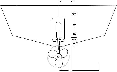
•Single drive boat - Refer to Figure 1-1 . If your boat has one propeller (outboard or inboard), mount the transducer about 18" (455 mm) to the side of the boat’s centerline. To reduce any interference caused by air bubbles, choose the side on the downstroke of the propeller (usually the starboard side).
•Twin drive boat - If your boat has twin propellers (outboard or inboard-outboard), mount the transducer between the drives near the centerline of the boat. If the boat will be operated at high speeds, the transducer may be mounted closer to the centerline of the hull.
8 |
Transducers for Fishfinders |
•If the propeller can be turned to steer the boat, allow at least 2" (50 mm) beyond the swing radius of the propeller. This will prevent the propeller from damaging the transducer when it is turned.
Approximately 18 in (457 mm) clearance
Be sure to allow at least 2 in (50 mm) beyond the swing radius of the propeller
D4871-2
Figure 1-1: Transom Mount Transducer Location
•Do Not mount the transducer behind any hull fittings, intakes or other parts extending from the hull that may cause turbulence or air bubbles.
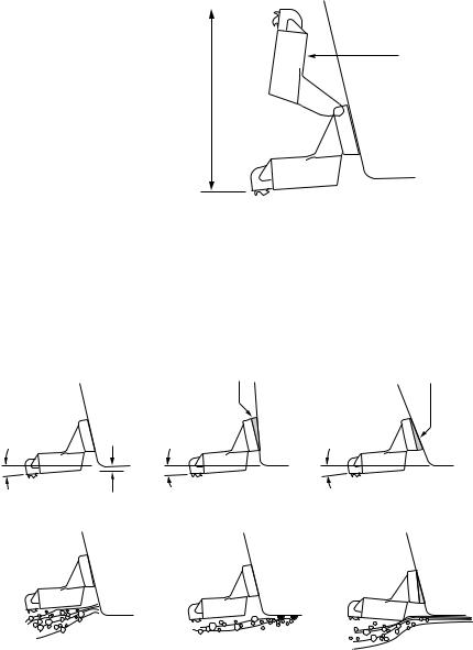
•The bracket has a quick-release mechanism, shown Figure 1-2 . This allows the transducer to flip up if it hits any debris or the bottom. Allow enough clearance above the transducer for it to swing upwards completely – this is about 10" (254 mm), measured from the bottom of the transom.
Chapter 1: Overview |
9 |
|
|
|
|
Transducer in released position
Allow a clearance of at least 254 mm (10 in)
D4872-2
Figure 1-2: Transom Mount Transducer - Quick-release Bracket
•On a boat with a fiberglass hull, the leading edge of the transducer should extend 1/8" (3.2 mm) to 1/4" (6 mm) below the bottom edge of the hull as shown in Figure 1-3 . On an aluminum hull, the transducer should extend a bit more – 1/4" (6 mm) to 3/8" (9 mm)
•If the boat will be trailered, be sure the transducer will not hit any rollers, bunks or fittings on the trailer.
Average transom angle - |
Vertical transom - |
Sloping transom - |
no wedge necessary |
place wedge this way |
place wedge this way |
2° to 5° |
2° to 5° |
2° to 5° |
For fibreglass hull – 1/8 to 1/4 in (3.2 to 6 mm)
For aluminium hull – 1/4 to 3/8 in (6 to 9 mm)
No! No!
The bow of the transducer |
Rivets on the hull are |
is above the bottom of the |
creating bubbles. Lower |
transom, creating cavitation. |
the transducer a bit. |
No!
D4873-2
The rear of the transducer is too high, creating cavitation.
Figure 1-3: Transom Mount Transducer - Vertical Position
10 |
Transducers for Fishfinders |
Thru-hull Transducer and In-hull Transducer
Similar consideration should be given to the location of thru-hull and in-hull transducers. Figure 1-4 shows the best transducer location for different hull types.
•Displacement hull powerboat – Locate at 1/3 aft load waterline length (LWL) and 6 - 12" (150-300 mm) off the centerline on the side of the hull where the propeller is moving downward.
•Planing hull powerboat – Mount well aft, on or near the centerline, and well inboard of the first set of lifting strakes to ensure that it is in contact with the water at high speeds. Mount on the side of the hull where the propeller is moving downward. Outboard and I/O – Mount just forward of the engine(s). Inboard – mount well forward of the propeller(s) and shaft(s). Step-hull – Mount just ahead of the first step.
Boats capable of speeds above 25 kn (29 m.p.h.) – Review transducer location and operating results of similar boats before proceeding.
•Fin keel sailboats – Mount to the side of the centerline and forward of the fin keel 1 - 2 ft (300-600 mm).
•Full keel sailboats – Locate amidships and away from the keel at the point of minimum deadrise angle.
•Fiberglass Hulls – Since the hull absorbs acoustic energy, transmitting through the hull reduces the sensor’s performance. Fiberglass hulls are often reinforced in places for added strength. These cored areas contain balsa wood or structural foam, which are poor sound conductors. If you cannot avoid locating the sensor over coring, follow the instructions for Installation in a Cored Fiberglass Hull on page 29.
•Thru-hull Transducer Headroom– Allow adequate headroom inside the vessel for the height of the thru-hull housing, tightening the nuts and removing the insert. The minimum headrooms are:
With fairing: 10" (254 mm) Without fairing: 12" (305 mm)
•In-hull Transducer – Find a location where the fiberglass is solid:
There are no air bubbles trapped in the fiberglass resin. There is no coring, flotation material, or dead air space sandwiched between the inside skin and the outer skin of the hull.

Chapter 1: Overview |
11 |
Displacement hull
Pressure waves
1/3 Aft
Load waterline length (LWL)
6 -- 12 in

 (150 -- 300 mm)
Planning hulls
Outboard and I/O
Inboard
Full keel sailboat
Step hull |
Fin keel sailboat |
D4857-2
Figure 1-4: Best Location for Thru Hull Transducer
Loading...