

Page 1
Remote Monitoring
Setup Guide
QS SERIES DVR MODELS
PC with Windows
Operating System
iPhone
Setup Guide for Remote Internet and Smartphone Monitoring,
MyQ-See DDNS, and Email Notification
Android
BlackBerry*
* Select Models
1
Page 2
Thank You for Choosing a Q-See Product!
All of our products are backed by a conditional service warranty covering all hardware for 12
months from the date of purchase. Additionally, our products also come with a free exchange
policy that covers all manufacturing defects for one month from the date of purchase.
Permanent upgrading service is provided for the software and is available at www.Q-See.com.
Be certain to make the most of your warranty by completing the registration form online. In
addition to warranty and technical support benefits, you’ll receive notifications of product
updates along with free downloadable firmware updates for your DVR. Register today at
www.Q-See.com!
Please see the back of this manual for exclusions.
About this Manual
This remote monitoring guide contains information extracted from the user’s guide and
presents it in this smaller document for your convenience. and was accurate at the time it
was completed. However, because of our ongoing effort to constantly improve our products,
additional features and functions may have been added since that time and on-screen
displays may change. We encourage you to visit our website at www.Q-see.com to check for
the latest firmware updates and product announcements.
Throughout the manual we have highlighted warnings and other important information that will
assist you in operating your new system in a safe and trouble-free manner. Please take the
time to read and follow all instructions and pay attention to alerts as shown below:
IMPORTANT! Red boxes with this icon indicate warnings. To prevent
possible injury or damage to the product, read all warnings before use.
NOTE! Text in blue boxes with the Information icon offer additional guidance
and explanations about how to make the most out of your system.
© 2012 Q-See. Reproduction in whole or in part without written permission is prohibited. All
rights reserved. This manual and software and hardware described herein, in whole or in part,
may not be reproduced, translated, or reduced to any machine-readable form without prior
written approval.
Trademarks: All brand names and products are trademarks or registered trademarks of their
respective owners.
Q-See is a registered trademark of DPS, Inc.
Disclaimer: The information in this document is subject to change without notice. The
manufacturer makes no representations or warranties, either express or implied, of any kind
with respect to completeness of its contents.
Manufacturer shall not be liable for any damages whatsoever from misuse of this product.
2 3
Page 3

TABLE OF CONTENTS
4. MINIPLAYER SOFTWARE 38
4.1 Installation 38
1. REMOTE ACCESS 6
Minimum System Requirements 6
1.1 Connecting your DVR to a Network 7
Before you get started 7
Obtaining an IP Address 8
1.2 Opening Ports 10
Option 1: UPnP 10
Option 2: Opening Ports Using DMZ 11
Option 3: AT&T U-verse® 2Wire® Routers 12
Confirming That Ports are Opened 13
1.3 Static Internal IP (Network) Address 14
1.4 Connecting Via a Modem (PPPoE) 15
1.5 Setting up Dynamic Domain Name Service 16
1.6 Resolving Connection Issues 17
Determine the Number of Routers on the Network 17
Setting Up DMZ in Router 2 19
2. E-MAIL NOTIFICATION 20
3. REMOTE MONITORING 22
3.1 Accessing Your DVR Remotely 22
Logging into the DVR 23
Resolving Connection Issues 24
4.2 Operation 39
5. MOBILE SURVEILLANCE 40
5.1 Enabling Mobile Surveillance 40
5.2 Using QS View 41
Logging into your DVR 41
Live View 44
Application Controls 46
Playback 48
Settings 50
More 51
Q-SEE PRODUCT WARRANTY 52
Questions or Comments? Contact Us 53
3.2 Remote Monitoring 29
Live View 29
3.3 Playback 35
3.4 Configure 36
Date/Time 36
User 36
Network 37
Comm 37
Local Settings 37
Rev. 3.1 12/31/12
4 5
Page 4
REMOTE ACCESS
In order to access your DVR remotely, you must connect it to a router or a modem. Using
a router allows you to connect to your DVR from other computers on your LAN (Local Area
Network) in addition to over the Web. Directly connecting to a modem makes your DVR
available for connection through the Internet only.
If you are using a router and wish to access your DVR from outside your LAN either over the
Internet, or from your mobile device, then that router must be connected to the Internet. The
instructions below will guide you through the process of configuring your DVR for remote
access. Once completed, you will be able to access and control your system using one of
two addresses. You will have a local IP address usable by computers connected to the same
router as your DVR. This address can also be used by wireless devices as long as they are
able to also connect to your router’s WiFi signal. Once you leave the area covered by your
local network, you will need to use a second address to access the DVR. This is the address
which will allow you to connect to your system from anywhere in the world with Internet
access. And, by using Q-See’s free DDNS service, MyQ-See.com (more on this later), you’ll be
able to do so using a conventional web address.
If you are using a router, proceed with Section 1.1. If you are connecting directly to the
Internet via a modem then begin with Section 1.4.
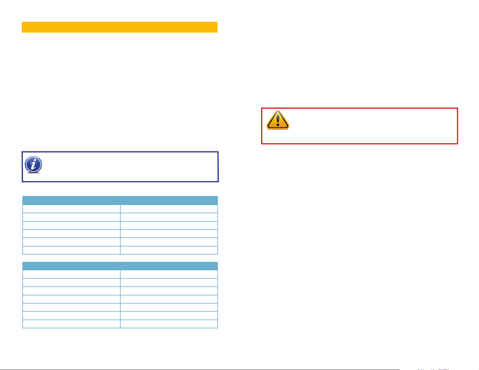
NOTE! In order to properly connect to your DVR from your computer, your
network connection and computer system should both meet certain minimum
specifications shown below. Performance will obviously be better if your
specifications are better than the mimimum.
CHAPTER 1
MINIMUM SYSTEM REQUIREMENTS
Computer
Min Video Ram 512MB for 4 to 8 cameras
1GB for 16 cameras
Video Card Must support Direct Draw
Processor 2.66MHz single or dual core
Macintosh System OSX 10.7 or 10.8
Windows XP, Vista, 7, 8
1.1 CONNECTING YOUR DVR TO A NETWORK
First and foremost, you will need to physically connect your DVR to a router. This router can
be part of an existing network of computers, or it can be the router/modem supplied by your
Internet Service Provider (ISP) to connect you to the Internet. This connection will be made by
plugging the included Ethernet cable into the port on the back of the DVR marked RJ45. Your
DVR is not designed to be connected wirelessly to a network. It is also recommended that the
router that the DVR is connected to should be connected directly to the Internet rather than
to another router if Internet access is desired as multiple routers can create problems with
connectivity. You will also need to have a computer connected to the same router - at least
temporarily - to make certain settings. If, after following the instructions you are still not able
to access your DVR, please see Section 1.6 Resolving Connection Issues later in this
chapter.
IMPORTANT! If the Startup Wizard reported success in connecting
your DVR to the Router and the Internet, you should proceed directly
to Confirming That Ports are Opened at the end of Section 1.2.
Attempting any of the steps listed in the rest of Section 1.1 will cause
connection problems.
BEFORE YOU GET STARTED
You will need to have:
• Your router’s brand, model number and manual. The manual is also usually available on your
router’s manufacturer’s website.
• The “Manuals and Software” CD that came with your DVR. It contains necessary software
and links to other important programs which are mentioned in this guide.
• Your router’s password (the default password should be in your router’s manual).
Network Connection
Internet Connection Speed at the DVR 1Mbps download
1Mbps upload for 4 to 8 cameras
2Mbps upload for 16 cameras
Internet Connection Speed at the Computer 1Mbps upload
1Mbps download for 4 to 8 cameras
2Mbps download for 16 cameras
You can check the speed of your connection at both ends by going www.SpeedTest.net
from both a computer attached to the same router as the DVR as well as the remote computer
which you will be using.
6 7
Page 5
OBTAINING AN IP ADDRESS
Each device on a network - both a LAN or the Internet - has a specific IP address. This
address is what allows different devices on the network to communicate with each other. Your
QS-series DVR displays both of these addresses in the Network Information window. If
you were successful in connecting your DVR to the network using the Startup Wizard, or by
following the instructions on the Remote Networking Poster, you may have already written this
information down.
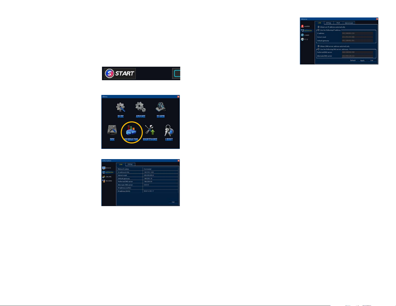
STEP 1. Using the mouse, click on the
Start button in the Control Bar to
open the Main Menu.
PICTURE 1-1
STEP 2. Select Information in the Main
Menu window.
PICTURE 1-2
If you were unable to connect to your router,
open the Advance menu and select the
Network icon on the left of the menu. Make
sure that the radio button for Obtain an IP
address automatically is selected.
Click Apply before exiting and then return
to the information window to view the LAN
IP address. You can use this address in the
next steps to get your DVR connected to the
Internet.
If you are still unable to establish a connection, make certain that the network lights on the
Ethernet port on both the router and the DVR are lit. If not, it is likely that your Ethernet cord is
faulty and it should be replaced. You may also connect to a different port on the router as well.
PICTURE 1-4
STEP 3. Click on Network on the left
side of the menu.
STEP 4. Write down the series of
numbers to the right of IP address
(LAN), Default Gateway and IP
address (WAN).
PICTURE 1-3
LAN, or Local Area Network, refers to your network of computers within your home or office
which is connected to the Internet through your router. Use this number for accessing your
DVR from a computer on the same network, or when using a mobile device using the wireless
signal from your router. Please note that when you leave the area of this WiFi signal, you will
need to access your DVR using the WAN address.
WAN, or Wide Area Network, is another name for the Internet. If you are away from your
network, such as at home accessing your DVR at work, you will need to enter the WAN
address into the browser or mobile remote monitoring app to be able to view it.
8 9
Page 6
1.2 OPENING PORTS
To make your DVR accessible from outside of your local network, you have to “forward” ports
80, 100 and 9000 through your router to your DVR’s IP address. We present two options
which cover the majority of users - UPnP and Port Forwarding. You will only need to use
one or the other. If you are unable to connect your DVR to the Internet using either of these
procedures, the likely cause is the presence of multiple routers on your network. The solution
is covered in Section 1.6 Resolving Connection Issues.
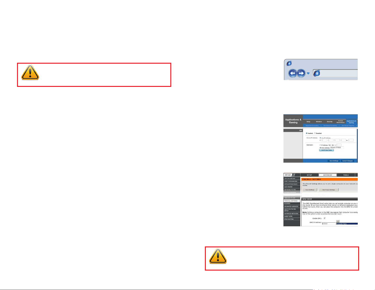
OPTION 2: OPENING PORTS USING DMZ
Accessing your router’s DMZ controls:
The exact location of DMZ within the router’s settings vary by manufacturer so please consult
your router’s manual for the location of this feature. The method for accessing your router’s
settings, however, is pretty standard. If your router is an AT&T 2Wire router, please see
Option 3.
IMPORTANT! If you connect your system to your network using UPnP
you should NOT forward your ports as described in DMZ, as it will create
connectivity problems. You may skip to Confirming that Ports are
Opened.
OPTION 1: UPNP
The QS series of DVRs come configured to take advantage of the latest networking
technology, UPnP or Universal Plug ‘n Play right out of the box. If you have an UPnP-enabled
router, you will only need to plug the DVR into your network and you will then be able to
proceed to the end of this section.
Consult your router’s manual to determine whether it has UPnP or not. Please note that, as
of this writing, 2Wire brand routers, which are used by AT&T Uverse, do not have the UPnP
feature. If you do not have a UPnP-enabled Router, you will need to use the DMZ method
described immediately below this section to forward your ports. There are special instructions
for use with AT&T 2Wire routers listed in in Option 3.
Proceed to Confirming That Ports are Open the end of this section for instructions on
how to confirm that your ports are open using an online tool.
STEP 1. On a computer connected to
the same router as the DVR, open a
web browser and enter the Gateway
(Router’s IP address) into the browser
window’s address bar to access your
router. This address is also shown
in the Network Information window
used to obtain your IP address.
STEP 2. Locate the DMZ settings in
your router. Each manufacturer is
different so please consult your
router’s manual for the location of this
setting. Two examples are shown at
right.
STEP 3. Enable DMZ.
STEP 4. Enter the DVR’s IP address.
STEP 5. Click on Apply or Save to
preserve your settings.
Browser - Windows Internet Explorer
hp://10.6.196.6
PICTURE 1-5
PICTURE 1-6
PICTURE 1-7
IMPORTANT! If you connect your system to your network using UPnP
you should NOT forward your ports as described in DMZ, as it will create
connectivity problems. You may skip to Confirming that Ports are
Opened.
10 11
Page 7
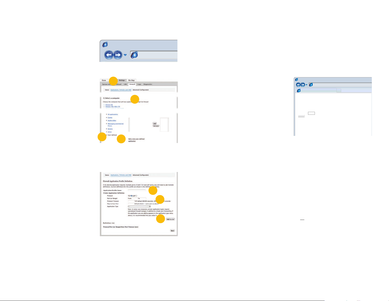
OPTION 3: AT&T U-VERSE® 2WIRE® ROUTERS
Page Safety Tools
Please note that the following steps are unique to the 2Wire brand of routers used by AT&T
and they should not be attempted on other models. Rather, you should use Option 1 or 2.
STEP 1. On a computer connected to
the same router as the DVR, open a
web browser and enter the Gateway
(Router’s IP address) you obtained
in Part 1 into the browser window’s
address bar to open your router’s
Admin Screen.
Browser - Windows Internet Explorer
hp://10.6.196.6
PICTURE 1-8
2
STEP 2. Click on the Settings tab and
then Firewall. Once in Firewall,
click on Applications, Pinholes and
DMZ.
STEP 3. In the Select Your Computer
area locate your DVR’s IP address
and click on it.
STEP 4. Scroll down to select User
Defined.
STEP 5. Click on Add a new user-
defined application.
STEP 6. In the box labeled Application
Profile Name, enter DVR.
STEP 7. Ensure that TCP is selected.
4
3
5
PICTURE 1-9
6
8-10
STEP 8. Enter 80 in the From and To
boxes for Port (or Range).
9
STEP 9. Leave the next two boxes blank
to use the default settings.
PICTURE 1-10
STEP 10. Click on Add to List. Your
router will require you to log in to
accept the settings. If you have not
created your own password for your
router, it is the 10-digit System Key
printed on the label on your router
between the square brackets “[ ]”.
STEP 11. Once your settings have been confirmed, repeat Steps 8-10 twice more.
Enter 100 for the From and To ports the next time, and 9000 the last time.
STEP 12. Click on Back and then select DVR from the list of Applications. Clicking on
Add and then Save.
CONFIRMING THAT PORTS ARE OPENED
Whether you used UPnP or DMZ to open your ports, you should confirm that they have
been opened without being blocked by going to www.canyouseeme.org using a computer
connected to the same router as the DVR.
STEP 1. Enter “80” into the box labeled
“What Port?”
STEP 2. Click on the Check button
STEP 3. You should see a green
“Success” message.
If you get a red error message, you will need
to return to the DVR’s Network Settings
page and change the Web Port to 81, 83
or 85 and click Apply to save your changes.
The DVR will need to reboot to use the new
settings. You can then reattempt the check
by entering that new number in the Port field.
STEP 4. Repeat for ports 100 and 9000. If ports 100 and 9000 are blocked, then use a
number in that range (ie; 110, 9100, etc.)
This website will also display your Public IP address near the top of the page above the box
where you entered your port number. If your DVR was unable to provide you with a WAN
number, due to setup difficulties, this is that number. Use this number to access the DVR
using a web browser or your mobile device from outside of your local network (away from
the building in which your DVR is located). Please note that if you had to use a different port
number than 80 for the web port, you will have to add a colon (:) and that port number to the
end of the address shown. Example 82.919.622.24:81.
Browser - Windows Internet Explorer
hp://canyouseeme.org/
Open Port Check Tool
CanYouSeeMe.org - Open Port Check Tool
This page will serve as a free utility for remotely verifying a port is open or closed. It will
be useful for users who wish to check to see if a server or ISP is blocking certain ports.
Your IP: 81.919.622.24
What Port?
Check
Success: I can see your service on
81.919.622.24 on port (80)
Your ISP is not blocking port 80
PICTURE 1-11
12 13
Page 8
1.3 STATIC INTERNAL IP (NETWORK) ADDRESS
Most routers assign connected devices a random IP address that is not currently in use by
another device on your internal network. When a router or networked device reboots due to a
power loss or other issue, the addresses will change and the port forwarding configuration will
no longer work. For that reason, we recommend changing your DVR’s network setting to a
xed, or “static” IP address which will not change.
IMPORTANT! As of this writing, 2Wire brand routers do not support Static
IP. Because of this, in the event that your router has to restart, you will need
to repeat the steps to obtain the new IP address. Connecting the router to an
uninterruptible power supply (UPS) can prevent this issue.
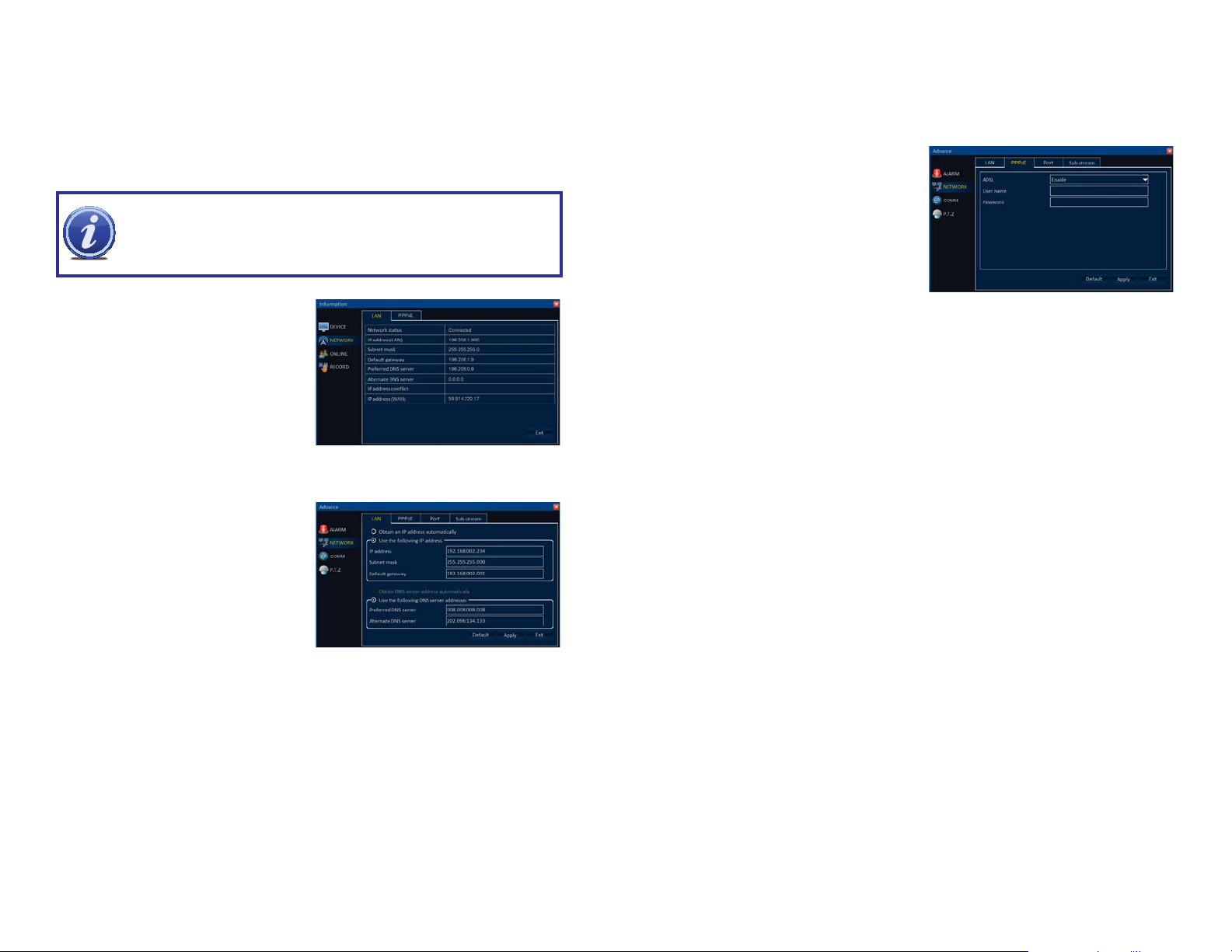
1.4 CONNECTING VIA A MODEM (PPPOE)
If you are going to attach the DVR directly to a DSL or Cable modem instead of a router you
will want to select the PPPOE option in the NETWORK options. This method is instead of
UPnP or DMZ and only applies if you are not using a router.
Contact your ISP for the User Name and
Password needed for the Internet account.
Click on the PPOE tab and then select
Enable from pull-down menu. Enter the User
Name and Password into the appropriate
fields.
STEP 1. Open the Information menu
and select Network.
STEP 2. Write down the information for
IP Address (LAN), Subnet mask,
Default gateway and Preferred DNS
Server (you’ll only need the one, not
the Alternate).
PICTURE 1-12
STEP 3. Exit the Information menu and
return to the Advance menu and
select Network.
STEP 4. Click the radio button for Use
the following IP address.
STEP 5. Enter the information obtained
in Step 2 into the appropriate fields.
STEP 6. Click Apply to save your settings before exiting the window.
Proceed on to Section 1.5 Setting up Dynamic Domain Name Service to create a
custom web address that you can use instead of entering the IP address when monitoring
remotely.
PICTURE 1-13
PICTURE 1-14
14 15
Page 9
1.5 SETTING UP DYNAMIC DOMAIN NAME SERVICE
This is an optional step which allows you to take advantage of Dynamic Domain Name
Service, or DDNS. Not to be confused with DNS in the previous section, DDNS allows you to
enter a conventional web address when remotely logging into your DVR from outside of your
network. It also allows you to avoid having to repeat steps in Obtain an IP Address when/
if your ISP reassigns IP addresses. Q-See offers DDNS service for free at www.MyQ-See.com
and your DVR is configured accept account information from that site.
STEP 1. Open a browser window and go
to www.MyQ-See.com
STEP 2. Register with the website and
follow the instructions for creating
a domain name. The website will
display your pubic IP address and
your domain name which will look like
this: http://example.MyQ-See.com
NEW USER REGISTRATION
EMAIL ADDRESS
PASSWORD
PASSWORD
CONFIRM
FIRST NAME
LAST NAME
SECURITY
QUESTION..
ANSWER
CONFRIM
YOU’RE HUMAN
PICTURE 1-15
My first phone number
New Captcha
Enter the text you see above
Submit
Reset
Submit
Reset
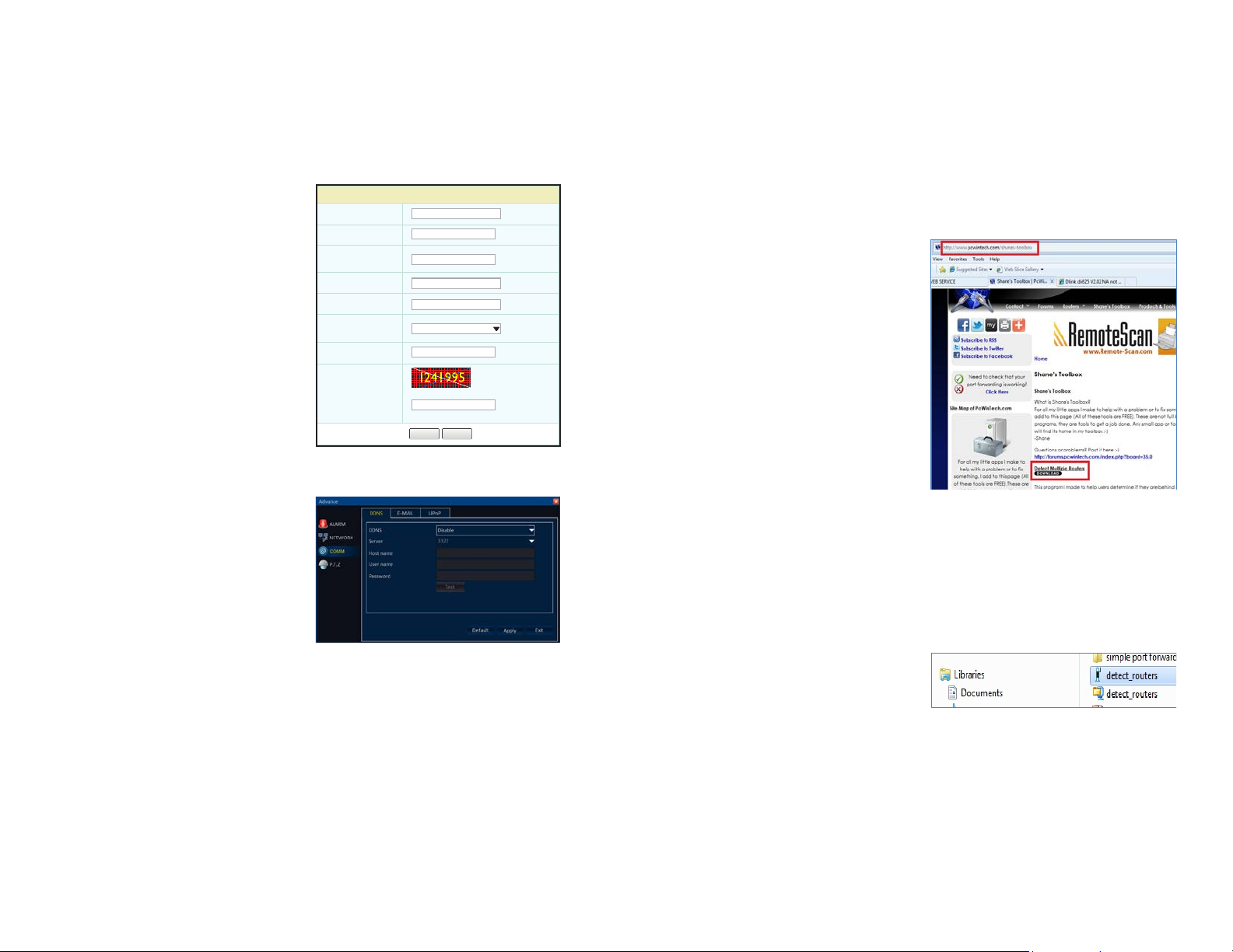
1.6 RESOLVING CONNECTION ISSUES
There are several hardware-related situations which can prevent the DVR’s port from being
properly forwarded. The presence of multiple routers or the routers not featuring UPnP or
DMZ are the two most common issues.
DETERMINE THE NUMBER OF ROUTERS ON THE NETWORK
If there is more than one router between the DVR and the Internet it will block communication
to and from your system. To find out the number of routers on your network, you will need to
download a FREE router detection program.
STEP 1. Go to http://www.pcwintech.
com/shanes-toolbox
STEP 2. Click on Detect Multiple
Routers to begin the download.
STEP 3. Return to the Advance Window
STEP 3. Unzip the application to install it.
PICTURE 1-17
in your DVR and click on the COMM
button on the left.
STEP 4. In the DDNS tab, select Enable
from the pull-down menu. Next, enter
your new MyQ-See address in the
Host Name field along with the User
Name and Password you used to
create the account.
STEP 5. Click on Test to ensure that your settings are correct. You should receive a
PICTURE 1-16
STEP 4. Click on the detect_routers
application to run it.
PICTURE 1-18
pop-up window indicating success or error.
IF YOU RECEIVE AN ERROR MESSAGE: Check your entries to ensure that they are
correct. Also check that the DNS address from the router is the same as shown in the Primary
DNS address field within the Advanced Network Settings window towards the bottom of
the LAN tab (Picture 1-13).
STEP 5. Click Apply to save your settings before exiting the window.
16 17
Page 10

STEP 5. Click on CHECK NOW to
detect how many Routers are in the
network.
PICTURE 1-19
STEP 6. If there is only one router detected, and you are using UPnP, then you will need
to turn off UPnP in the DVR by opening the COMM menu in the Advance window
and disable it in the UPnP tab. Attempt to connect using DMZ as described in
Section 1.2 Opening Ports.
If you are using DMZ, check to make sure that the UPnP option is turned off.
If Multiple Routers are Detected
If there are multiple routers, you will see a
display similar to Picture 1-20.
If so, it may be preferable to connect your
DVR and computer to the router that
connects directly to the Internet. However,
this is not always possible depending upon
your particular situation.
SETTING UP DMZ IN ROUTER 2
STEP 1. Login into Router 1 by putting
the IP of Router 1 into the Internet
Explorer browser, as in the example
shown in Picture 1-21 where the IP
address of Router 1 is 192.168.0.1
STEP 2. Find the status page on the
router settings that shows the WAN/
Internet IP address and write it down
this WAN IP address.
STEP 3. Log into the Router 2 by putting
the IP of Router 2 into the Internet
Explorer browser, as in example
shown in Picture 1-21 where the IP
address of Router 2 is 192.168.1.1
STEP 4. Find the DMZ page in the
router settings.
STEP 5. Enter the WAN IP for Router 1
into the DMZ page and enable DMZ.
NOTE! If you do not have a DMZ setting in the router, check to see if there
is a Bridge setting. If so, then use the Bridge setting instead of DMZ.
STEP 6. Save your changes.
You have forwarded the ports on the router to which the DVR is connected, to the IP address
of the DVR, and set the primary router to pass the connection to this router.
PICTURE 1-21
PICTURE 1-20
In this case, you will need to proceed with the next section and set up DMZ in the second
router to allow communications to pass through it from the first. If only one router is detected
you will need to consult your router’s manual.
18 19
Page 11

E-MAIL NOTIFICATION
The system can send an email notification to up to five addresses with an attached JPEG
snapshot recorded by one or more cameras when triggered by an alarm event.
Setting the DVR to take snapshots and send e-mail is done in the Alarm section of the
Advance menu. These are two options available in the Trigger settings for each camera.
Setting up these triggers is covered in Section 5.2 Advance Menu in the User Manual
that came on the same CD as this document. It is also available for free download through our
online help site at Q-See.com/support.
CHAPTER 2
STEP 1. Create a Gmail account for the
DVR to use to send e-mail.
PICTURE 3-1
Your DVR will need to be connected to the Internet - either through a router or by being
directly connected to a modem - in order to be able to send out email alerts.
You will need to provide the DVR with a valid e-mail address that it can use to send the alert
messages. These settings are made in the Communications section of the Advance menu.
For the purposes of this guide, we will use Google’s Gmail service because it is free and offers
a higher volume of e-mails on a daily basis. The settings shown in the instructions will be
that for Gmail. Other services’ settings may be different, but can be found on their respective
webpages.
If you have a corporate mail server, you will need to consult with your IT department regarding
proper settings.
NOTE! Depending upon your settings, the system can generate a lot of e-mail
alerts. For that reason, we recommend setting up a dedicated e-mail address
specifically for the system to send alert notices. If you do not have your own
e-mail system (such as a corporate mail server) you should consider using a
free e-mail provider. However, because many free e-mail services allow only a
limited amount of e-mail traffic we specifically recommend using Google’s Gmail service with
its higher limit. Similarly, you will want the alert e-mails to go to a different account than the
one sending them. This will ease your management of these alerts.
STEP 2. On your DVR, navigate to the
Advance menu.
STEP 3. Select Comm from the left side
of the screen and click on the E-mail
tab.
STEP 4. Select Enable from the pull-
down menu.
STEP 5. Choose whether you want e-mails sent out immediately upon an alarm, or if you
want a delay.
STEP 6. Enter the following information into the respective fields:
Mail Server (SMTP) Enter the SMTP address of your email server. For example,
smtp.gmail.com
Port Enter the SMTP port of your email server. Gmail’s is 465.
Connection Security Leave this turned off. Only advanced users should enable
this option.
User Name The “from” address of your alerts.
Password Enter the password of your sending email account
To Enter the destination email address for your notifications. This should be a
different e-mail address than the sending account to avoid possible errors. You
may enter up to four other e-mail accounts using the CC fields.
PICTURE 3-2
STEP 7. Click Test to verify your settings. You should receive a confirmation message in
a pop-up window.
STEP 8. Click APPLY to save your settings before exiting the window.
20 21
Page 12

REMOTE MONITORING
CHAPTER 3
3.1 ACCESSING YOUR DVR REMOTELY
Once you have configured the network settings on the DVR to match those on your router and
forwarded the ports needed by the DVR to enable remote access over the Internet, you will be
ready to remotely view your cameras using your mobile device or your computer.
LOGGING INTO THE DVR
Open a new browser window and enter the IP address (WAN or LAN) appropriate to your
network, or use the DDNS address you created in Section 1.5 into the address bar just
as you would for any regular web address. You may get an alert message warning about
an attempt to modify Internet Explorer. Q-See is the publisher of the helper application. You
should allow it to proceed.
Windows users will be able to log into their system in Internet Explorer using a plugin called
View DVR. It is strongly suggested that you be running the latest version of Internet Explorer
(currently IE9). The instructions beginning on the next page will describe the process using
both version 8 and 9 of Internet Explorer.
Users of Macintosh computers will need to download the free View Client software which is
available from our support portal at:
http://qsee.custhelp.com/app/answers/detail/a_id/1545/kw/qs494
You can click on the above link, above, to go directly to the download page.
View Client will work with OSX versions 10.7 and 10.8. Version 10.6 is not compatible.
Use of View Client will be largely along the lines of View DVR with the exception that video
cannot be recorded onto the computer. Video recorded on the DVR may be searched and
played back using View Client. Additionally, the location of certain controls is slightly changed
from View DVR. This manual will use screenshots of View DVR for the most part. After
logging in to View Client, Macintosh users may proceed to Section 3.2.
Mobile remote monitoring will be covered in Chapter 4.
After the page finishes loading, you will see a log in screen. Enter the same user name and
password combination that you use to login into the DVR itself. You may also choose your
preferred language at this time.
PICTURE 3-1
Upon logging in, you should see a live feed from your cameras.
If you experience problems such as lack of video or other issues, please see Resolving
Connection Issues immediately following. Usage instructions begin in Section 3.2.
PICTURE 3-2
22 23
Page 13

RESOLVING CONNECTION ISSUES
Because users, other programs and even Windows itself modify Internet Explorer, some users
may experience difficulty with displaying live video after accessing their DVR through that
browser. There are two methods used to resolve this issue that cover the majority of users:
installing a plug-in for IE, or turning off User Account Control.
STEP 4. Select the desired user account.
STEP 5. Select Turn User Account
Control on or off
User Account Control for Windows Vista and Windows 7
Some users of computers using Windows Vista or Windows 7 operating systems may receive
an error message informing of a codec that is missing or not installed. This conflict can be
resolved by turning off User Account Control (UAC).
Windows Vista
STEP 1. Open the Control Panel
(accessible by clicking on the
Windows icon in the lower left of your
screen.
PICTURE 3-3
STEP 2. Select User Accounts and
Family Safety.
PICTURE 3-4
STEP 3. Select “Add or Remove User
Account.”
PICTURE 3-5
STEP 6. Uncheck the box next to “Use
User Account Control (UAC) to help
protect your computer.”
STEP 7. You will then be asked to restart
your computer for the change to take
effect.
Windows 7
STEP 1. Open up the Start Menu
(accessible by clicking on the
Windows icon in the lower left of your
screen.
STEP 2. Type “uac” into the search bar
and hit ENTER. The User Account
Control will open or you will be offered
a link to click to open it.
PICTURE3-7
PICTURE 3-8
Microso Office Outlook 2007
Scky Notes
iTunes
Adobe Acrobat
All Programs
uac
PICTURE 3-9
PICTURE 3-6
Devices and Printers
Default Programs
Help and Support
Shut down
STEP 3. Move slider to lowest setting
and press OK.
24 25
Page 14
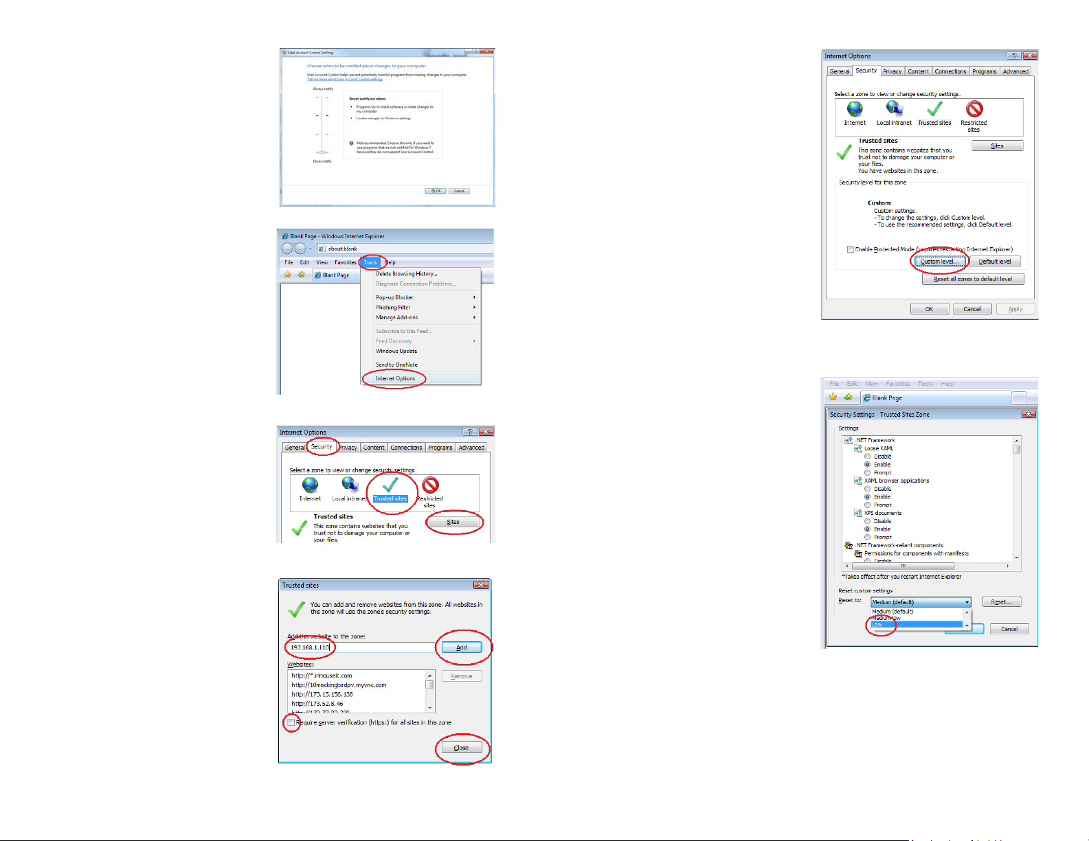
Setting Up ActiveX Control
STEP 1. Open Internet Explorer
STEP 2. Click on Tools
STEP 3. Select Internet Options in the
pull-down menu
STEP 4. Click on the Security Tab
STEP 5. Select Trusted Sites
STEP 6. Click on the Sites button
PICTURE 3-10
PICTURE 3-11
STEP 11. Click the Custom level…
button.
PICTURE 3-14
STEP 12. Pull down the “Reset to:”
menu button and select Low
PICTURE 3-12
STEP 7. Uncheck the “Require server
verification (https:) for all sites in
this zone” button.
STEP 8. Type the DVR’s IP address
(obtained during Network Setup)
or DDNS domain name into the “Add
this website to the zone:” box.
STEP 9. Click the Add button
STEP 10. Close the window.
PICTURE 3-13
PICTURE 3-15
26 27
Page 15

STEP 13. Click the Reset button
STEP 14. Click “Yes” when asked, “Are
you sure you want to change the
setting for this zone?”
STEP 15. Click OK
3.2 REMOTE MONITORING
The View DVR remote monitoring program’s default mode is the Live View window, which
shows video feeds from one or more cameras along with providing additional controls.
There are two other modes - Playback and Configure - which allow you to play back video
recorded on the DVR and change the settings on your system, respectively.
LIVE VIEW
The controls in this mode are limited to those that affect the viewing of live feeds from your
cameras.
STEP 16. Click Apply
STEP 17. Click OK
STEP 18. Close Internet Explorer
You are now ready to access the DVR using Internet Explorer.
Downloading the Plug-In
Another alternative is to download the plug in application directly.
The plug-in, named RM_N9dvrocx.zip can
be download by clicking on the Download
plug-in link on the Login screen.
Save the .zip file to your hard drive. You will
need to save or move it to a specific folder on
your computer.
Windows XP: C-Windows-System32 folder
Windows 7: C-Windows-SysWow64 folder
Once you have placed the file in the correct
folder, you will need to unzip (extract) the files
within that folder.
PICTURE 3-16
PICTURE 3-17
In multiple-camera display mode, the controls will affect only the screen outlined in green. You
can drag a camera’s video to another section of a multi-camera view where the feed that was
previously there will move to the now-empty location of the first channel. Double-clicking on a
channel in multi-camera display mode will change the mode to single-camera view. Doubleclicking it again will return to the multiple screen mode.
Switch to the Playback and Congure modes using the tabs at the top of the screen. You can
log out of the remote monitoring program from any mode by clicking on the Logout button in
the upper right corner for PC users. Users of View Client on the Macintosh only need to quit
out of the program.
The following page shows screenshots from both the View DVR plugin for Windows and
View Client for Macintosh, along with a table identifying key features.
Quit out of Internet Explorer and restart the program to connect to the DVR.
28 29
Page 16
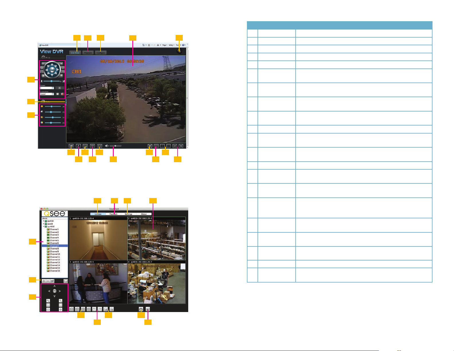
1 3
View DVR (PC)
6
7
8
9
View Client (Macintosh)
20
21
1 3 5
111413
10
2
12
PICTURE 3-18
2
4
151817
16
4
# Name Function
1 Live View Tab Sets program’s mode to Live View
2 Playback Tab Sets program’s mode to Playback
3 Congure Tab Sets program’s mode to allow you to configure the DVR
4 Video Display Displays video feeds from one or more cameras.
5 Logout Logs out of View DVR (Quit Net Client to log out on Mac)
6 PTZ Controls Control a PTZ camera directly, or cause it to begin a pre-
programmed function
7 Hide Controls Hides the left control panel, increasing viewing area (Not available
on Mac)
8 Picture Adjust Adjusts brightness, contrast,hue and etc. Only affects live video.
(Not available on Mac)
9 Snapshot Selected camera will capture a still image and save it to your
computer’s hard drive.
10 Record All channels will begin recording video. (Not available on Mac)
11 Open/Close
Window
12 Main Stream Uses the DVR’s main stream for monitoring. This requires
13 Sub Stream Uses a lower-resolution secondary stream from the DVR.
14 Mute/Volume
Control
15 Original/Full
Window
16 Full Screen Displays video feed(s) without controls. On systems with multiple
17 Multiple-display
modes
18 Previous/Next
Page
19 Close Screen(s)
20 Device List
21 Add/Delete/Edit
DVR (Mac Only)
Turns video feeds on or off
increased bandwidth.
Mutes or adjusts volume if there is an audio feed
Adjusts aspect ratio of video image to fill available space.
monitors, this will fill the primary monitor. Right-click to exit this
mode.
Depending on your DVR model, you have the option to
simultaneously view four or eight camera feeds at once.
Moves to previous or next group of cameras.
Close one screen (left button) close all screens (right button)
(Mac only)
The list of connected DVRs being monitored by View Client (Mac only)
Add and remove DVRs from the list of connected DVRs or edit the
connection details.
6
17 19
18
PICTURE 3-19
9
14
30 31
Page 17

PTZ Controls
The controls on the remote monitoring program allow you to control, but not configure an
attached PTZ camera. You will need to set up preset points and cruise lines on the DVR itself
as covered in Chapter 6 PTZ Cameras in the User Manual.
The controls themselves perform the same functions as on the DVR.
1
2
8
9
Color Adjustments (PC Only)
Because monitors differ in how they produce
color, and because adjusting the picture
may assist in identifying details the program
includes Color Adjustment controls.
These controls adjust brightness, contrast,
hue and saturation, but only affect the live
video being displayed within View DVR.
They do not alter the color of the video
being recorded either on your DVR or your
computer’s hard drive.
3
4
5
6
7
PICTURE 3-20
No. Item Function
1 Wiper Turns on camera’s wiper (if so equipped)
2 Iris- Closes iris, reducing light level
3 Focus- Adjusts focus
4 Zoom- Zoom out
5 Directional
Controls
6 Preset Select a preset point
7 Cruise Line Selects a cruise for the camera to follow
8 Light Turns on camera’s light (if so equipped)
9 Iris+ Opens iris, increasing light level
10 Focus+ Adjusts focus
11 Zoom+ Zoom in
12 Speed Adjust speed of camera’s movement
13 Call Goes to preset point
14 Start/Stop Begins or ends cruise
Click on arrows to move camera in desired direction.
10
11
12
13
14
PICTURE 3-21
Function Controls
The series of controls underneath the Live View window are divided into two primary groups.
The leftmost is concerned with functions of the remote viewing program while those to the
right control the display itself.
PICTURE 3-22
Snapshot and Record both save files to your computer’s hard drive, rather than to the DVRs.
The DVR may be recording files or capturing still images on its own at the same time, but
neither operation affects that on the other system.
The files will be saved into a destination file in your User folder (the folder with the name of the
user currently logged into the computer) with each channel having its own sub-folder. You may
specify a different destination for these files in the Configure mode by using Local Config.
Snapshots are saved in .jpg format while videos are saved in the .264 format which requires
use of the Miniplayer software that was included on your disk. Its use is covered Chapter 4.
Open/Close Window will end or restore the live feed from the cameras within Live View. This
can be used to temporarily hide the feeds without logging out of the application.
Main stream and Sub-stream are parallel data streams from your DVR. The Main stream is
larger, and therefore clearer, but motion can appear rough if there is not enough bandwidth. In
such cases, using the smaller Sub-stream can result in smoother movement while sacrificing
image quality. Your DVR always records to its hard drive using the Main stream.
Volume controls only function if there is an audio source, such as a microphone or audioenabled camera, connected to your DVR. You can mute the sound, or adjust the volume as
needed.
32 33
Page 18

Display Controls
These controls deal with how the video is displayed on your screen - full screen, multichannel, etc.
PICTURE 3-23
Original/Full window. Because displays have various aspect ratios (height versus width), and
because you may resize the browser window, View DVR may stretch out or otherwise distort
the camera video as it attempts to use the space available. Clicking this button will restore the
video to the proper aspect ratio, but may leave some unused black space within the frame.
Full Screen will hide all controls and display the video across the primary video monitor.
Right-clicking will exit this display mode.
3.3 PLAYBACK
The Playback function on View DVR functions in the same manner as the video playback on
the DVR itself. When you click on the Playback button, the Calender will appear showing
days with recorded video in red. The current date’s video will automatically be shown in the
timeline below the video displays. You can change the date you want to review simply by
clicking on it in the Calendar, or you may refine your search using the options directly below
it.
Multiple video display modes. These buttons allow you to view multiple video channels
at the same time. If your system does not have as many cameras as the display mode, the
unused channels will be black.
Page controls are used when you have more cameras than are being displayed on the
screen. Clicking on either button will cycle through the remaining cameras, retaining the same
display format - whether you’re in single or multiple camera mode.
PICTURE 3-24
You may optionally click Record List to view a list of the recorded files available for playback.
PICTURE 3-25
It is through this latter format that you are able to backup files from the DVR to the computer’s
hard drive by selecting one or more videos and then clicking Backup. These will be saved as
.264 format video files and stored according to your preferences set in the Local Config. You
may also take a snapshot from the video which will be recorded to your hard drive in the same
location that snapshots from live view feeds are stored.
PICTURE 3-26
The display controls at the bottom operate in the same manner as in the Live View. You will
only be able to view the recordings from four channels at a time due to bandwidth concerns.
34 35
Page 19

3.4 CONFIGURE
The Congure mode of View DVR allows you to remotely access and change most of the
settings on the DVR itself. With a few exceptions, accessing these settings through View
DVR is identical to accessing them on the DVR itself so we refer you to the User Manual for
in-depth information regarding these settings and their purposes rather than recapping them
here.
Instead, this section will concentrate on instances where the features are either not present on
the DVR or significantly different.
DATE/TIME
An added feature is the ability to synchronize the DVR’s clock to that of the PC. The DVR will
stay set to the PC’s local time until the user logs off and the next automatic update from the
selected time server occurs. To avoid this reset, disable the Auto update by unchecking the
box.
NETWORK
This area functions as it does on the DVR, but it is worth noting that making changes in this
area could result in your being unable to reconnect remotely to the DVR!
COMM
As with Network, above, changes made in this area through View DVR could result in you
being disconnected from the DVR and unable to reestablish a connection until such time as
you can make the settings at the DVR itself.
LOCAL SETTINGS
Unlike the rest of the areas in Configure, Local Settings only affects the computer you are
connecting to the DVR with.
PICTURE 3-29
PICTURE 3-27
USER
This area combines both the User settings in the Basic menu with the Online Users feature
in the Information window. In addition to being able to create new user accounts, you are
able to disconnect remote users if you are logged into the DVR as an admin.
PICTURE 3-28
Record pack time allows you to set a maximum duration for each file recorded. This allows
for easier playback and transfer of files. If a file reaches the maximum limit, the system will
immediately start a new file to continue the recording.
Snap/Record/Record backup paths This is where you set the destination location for the
computer to save snapshots, video recordings and backup files taken or downloaded in View
DVR. The default folder is in the User folder of the same name as the person logged into the
computer being used to monitor the DVR. Whether you continue to use this folder or create
your own, the program will save les into subfolders entitled “Capture” (snapshots), “Record”
(video recorded from live view) and “Backup” (recorded video uploaded from the DVR’s hard
drive. Each folder will be subdivided by the channel of the camera that recorded the image or
video.
36 37
Page 20

MINIPLAYER SOFTWARE
MiniPlayer is a standalone video playback program for Windows that will allow you to play
back the .264 format video recorded using the View DVR program and downloaded from the
DVR. Videos backed up at the DVR using a USB drive are saved in the more conventional .avi
format, but are generally too large to be transferred over the Internet from the DVR.
CHAPTER 4
4.2 OPERATION
MiniPlayer is a PC program who’s sole purpose is to play back .264-formatted video les and,
as a result, is straightforward in its operation. It is able to play back a single file at a time.
STEP 1. Select a file to play by clicking on the Open button located at the far left of the
controls under the timeline at the bottom of the screen.
Future versions of ViewDVR will provide .avi downloads. There are free software programs
available online which will convert .264 video to .avi format.
4.1 INSTALLATION
Locate the installation file, MiniPlayer_ENG_Setup.exe, on the CD that came with your DVR.
Double-click to launch it and follow the installation instructions.
When you have completed your installation,
MiniPlayer will be available in your Windows
Start Menu.
PICTURE 4-1
STEP 2. Navigate to the desired file which is saved in the destination folder that
you selected using the Local Settings function of View DVR (see Section 3.4
Configure).
STEP 3. Click on the le to begin playback. If the program shows the video as part of a
multiple-screen display (with the other three channels being blank), you can doubleclick on the channel with video to bring it to the single video display.
PICTURE 4-2
The controls are mostly straight forward and obvious in their functions and all controls display
their name if you hover the mouse cursor over a button. Start/Pause, Stop and Volume all
operate in the usual manner.
Additional controls include:
Speed - Playback speed is adjustable between 1/16x and 16x normal speed.
Forward Frame - Advance playback a single frame at a time.
Capture - Takes a still image from the currently displayed video.
Zoom In/Out - Zoom into our out of the video playback timeline for finer detail in selecting a
specific point in the recording. The mouse wheel can also perform this function.
38 39
Page 21

MOBILE SURVEILLANCE
CHAPTER 5
5.1 ENABLING MOBILE SURVEILLANCE
You can access your DVR from your Apple or Android smartphone or tablet. Search for
Q-See in the iTunes store or Android market to download this free mobile app. The same
application will operate on both phone or tablet. Be certain to select the QS Series version to
ensure compatibility with your system.
NOTE! Before you can use mobile access you need to setup the network
configuration on the DVR and forward ports 80, 100, and 9000 from the
router the DVR is attached to, to the IP address of the DVR as described in
Chapter 1.
NOTE: The bandwidth usage of monitoring your DVR remotely is roughly equivalent to
streaming a movie for the same duration.
5.2 USING QS VIEW
QS View software operates identically on both Android and Apple iOS phones and tablets.
The instructions below cover both platforms.
LOGGING INTO YOUR DVR
Once you’ve installed the QS View app, launch it as you would any other program.
PICTURE 5-1
Once the program has loaded it will display its
default mode, the Live View.
PICTURE 5-2
40 41
Page 22
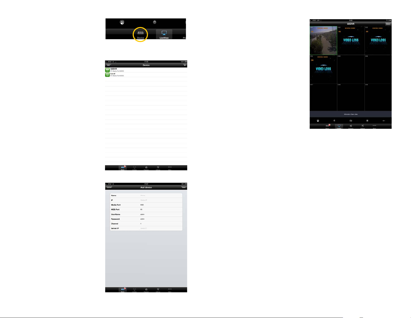
You will need to add your DVR to the Device
List in order to connect.
Once you’ve added your DVR to the list, you
can tap on it to connect to it.
Tap on the Device icon to open the Device
List.
To add a DVR to your list, tap the + (iOS)
or Add (Android) button in the upper right
corner.
Later, you can use this window to edit or
delete DVRs in your list by using the Edit
button on the upper left.
Clicking on the + or Add button opens
another window allowing you to enter
the DVRs IP address and other essential
information, such as the user name and
password. These are the same as you use to
log into the DVR.
PICTURE 5-3
PICTURE 5-4
While in Live View, you may switch between
Devices by tapping the Select button in the
upper right corner. This will cause a list of
your available DVRs to pop up allowing you
to choose which system to access.
PICTURE 5-6
It is recommended that you create two
“Devices” for each DVR. One should use the
local IP address for when you are accessing
the same network that the DVR is connected
to, while the other will use the WAN IP for
when you are connecting over the Internet.
PICTURE 5-5
42 43
Page 23

LIVE VIEW
QS View will open in nine-channel multi-display mode by default. Any “extra” channels beyond
what your DVR actually has will show up black while any channels that your DVR has but
without a camera connected will display “Video Loss”.
In portrait mode a series of controls will appear under the video.
Spreading your fingers on the screen will change the display mode to four- and then singlechannel display mode. A pinching action will increase the number of channels being displayed.
You can also double-tap on a channel to bring it to full screen view. Double tapping on it again
will return to the previous multi-screen mode.
In four-channel display mode, you can switch to the next group of four channels (if you have
an eight-channel DVR) by dragging your finger across the screen. Similarly, you may move
between single-channel views using the same page-turning motion. While in a single-screen
view, you can digitally zoom in on the video by spreading your fingers. A pinching motion will
zoom back out.
Most Live View functions will operate in portrait or landscape mode. Controls are hidden
while in landscape mode. Other functions, such as video playback, will be in portrait mode
only.
PICTURE 5-8
The upper row of buttons directly affects the Live View video. In order from left to right, the
buttons are: PTZ Controls, Local Record, Snapshot, Close Video and Volume.
PTZ Controls
Tapping the PTZ button will add PTZ controls to the a channel currently being viewed in fullscreen mode. These will be functional only on a channel that has a PTZ camera connected to
it. Touch the arrows to move the camera in the desired direction.
Spreading your fingers apart on the screen will cause the camera to zoom in while a pinching
motion will zoom it back out.
You are not able to make changes to the PTZ
settings through QS View, nor are you able
to activate cruises or automatically move to a
preset point.
PICTURE 5-7
PICTURE 5-9
44 45
Page 24

Recording Video
You are able to record live video locally to your device by tapping on the Record button.
These videos can be accessed and played back using the Playback function described later.
Tapping the Record button a second time ends the recording.
Device
You can switch between DVRs using either the Select button at the top of the screen or
the Device button at the bottom left. This latter button will display the number of available
systems next to its icon.
Snapshot
Tapping this button captures a still image from the selected camera. You are then given the
choice to save it or not. Images captured on the iPad and iPhone are saved to the device’s
Photos folder, while those captured on an Android device are available through the Playback
function.
Close Channel
This button turns off the feed from the selected channel but does not disconnect your device
from the DVR. The square icon is then replaced by a triangular “play” icon which will restore
the channel’s view to your device.
Volume Control
If you have an audio-enabled camera or a microphone connected to your DVR, you can turn
the audio on or off by tapping this button.
APPLICATION CONTROLS
The lower row of controls at the bottom of the QS View window are used switch modes with
the program as well as change the settings of the program itself.
Live View is the normal operating mode.
However, you can only add DVRs and edit
their profile with QS View from within the
Device List.
As was described at the beginning of this
chapter, to add a device, touch the + or
Add button (Apple or Android devices,
respectively) and then enter the information
needed to log in.
PICTURE 5-11
Touching the Edit button within the Device
List will add red icons to the left of the DVRs
within your list. You can tap on the DVR’s
name to edit its information - such as to
change the password.
When you have made your changes, tap the
PICTURE 5-10
Done (Apple) or Save (Android) to save them.
You must have more than one device in the
list to delete a system from your list. Tapping
on the red icon to the left of the device that
you want to remove will bring up a red Delete
button allowing you to remove the DVR from
your list.
PICTURE 5-12
46 47
Page 25

PLAYBACK
Along with viewing live feeds from your system, the playback feature is the other major
function of QS View. This function only operates in portrait mode. Only a single video may be
played back at a time.
Selecting Playback brings up a window
showing your options. You can play back
video recorded on the DVR (remote) or local
video which was recorded onto your device
by tapping on the Record button in Live
View. On Android devices, you may also view
the still images taken using the Snapshot
button in Live View using the Image View
function. Although this last option is shown as
Capture View in the iPhone/iPad version of
QS View, the images are automatically saved
to your device’s Photos folder so this feature
is not functional.
Select the type of playback you wish to
perform and the appropriate window will
open.
PICTURE 5-13
The playback controls are straightforward.
In addition to playing the video at normal
speed, the arrows to either side of the Play/
Pause button allow you to speed up or slow
down playback by a factor of two (1/2x to 2x
normal speed).
The Snapshot button allows you to capture
a still image from the recorded video. This
image will be saved in the same location as
snapshots taken from live video - in Photos
on the iPhone or iPad and within a folder
labeled Streaming on the SD card in Android
devices.
Volume allows you to mute any included
audio stream.
Tap on Playback in the upper left to return to
the list of videos.
Local Playback
Local files are videos recorded onto your
mobile device when you press the Record
button during Live View. Video from all
cameras will be recorded when you select
this operation.
PICTURE 5-15
Remote Playback
You are able to access - and view - videos
recorded onto your DVR’s hard drive from
your mobile device. When you select Remote
Playback, a calendar will appear showing the
current date. If that date has recorded files,
they will automatically appear in the list below
the Calendar. Dates with recorded video will
be shown in blue.
You may select a different date and which
channel(s) to search. The file list will show the
start and end times, along with which channel
made the recording. Double-tap upon a file to
begin playback.
PICTURE 5-14
Playback operates in exactly the same
manner as with remote playback.
Tap on Local Playback in the upper right to
return to the list of files.
You may double-tap on a video to begin
playing it, or you may tap on the arrow at the
far right.
To delete a video, simply touch and drag
within the white area to the right of the
file name and a Delete button will appear,
allowing you to remove the file from the list.
Image Playback
Available only on the Android version of QS View, Image Playback allows you to review still
images captured from Live or Playback video. These files are located on your device’s SD card
in a folder named Streaming where they may be copied, sent or deleted.
PICTURE 5-16
48 49
Page 26

SETTINGS
The Settings menu allows you to make certain changes to your DVR remotely. The options
listed in this menu mirror those on the DVR itself but aren’t nearly as complete. You cannot
access all of the funtions and options available on the DVR, including PTZ configuration, but
you are able to change the recording schedule, set up alarm responses and so on.
Full and complete descriptions of the
functions can be found within the User
Manual as well as earlier within this Remote
Monitoring Guide.
Use the Back button to exit a portion of the
Settings menu without leaving the menu
itself.
Worth noting, however, is the ability to access
the list of online users. In addition to being
able to create and modify user accounts from
your mobile device, you may also disconnect
another user from the system if you are
logged in using the Admin account.
As was stated earlier in the Remote
Monitoring portion of Chapter 3 of this
Guide, care should be exercised when
modifying any of the network settings as
changes may result in your being logged out
of the DVR with no way to reconnect until
settings are changed again at the DVR itself.
PICTURE 5-17
MORE
This last portion of QS View collects two different functions into a pair of submenus.
System
The settings within the System submenu include Main/Sub Stream, Network and PTZ camera
speed with the first two options giving you control of the amount of data being utilized by your
device. Keep in mind that streaming video from your DVR utilizes approximately the same
bandwidth as a streaming a movie or live video from another source. Depending upon your
data plan, you may find it better to utilize only the lower-bandwidth substream. Disabling this
option will provide reduced image quality as the device will only use the substream. But, it will
not use as much data. Turning on Only Wifi in the Network option will prevent your mobile
device from streaming video using 3G/4G data networks.
The last option does not affect bandwidth, but allows you to adjust the speed at which the
PTZ camera operates in Live View mode.
About
This other submenu provides basic information about the QS View software - which version
you are running and its release date.
50 51
Page 27

Q-SEE PRODUCT WARRANTY
Q-See is proud to back all of our products with a conditional service warranty covering all
hardware for 12 months from the date of purchase. Additionally, our products also come with
a free exchange policy that covers all manufacturing defects for one month from the date of
purchase. Permanent upgrading service is provided for the software.
Liability Exclusions:
Any product malfunction or abnormalities in operation or damage caused by the following
reasons are not within the free service scope of our company:
1. Equipment damage caused by improper operation.
2. Improper equipment operation environment and conditions (e.g., improper power,
extreme environmental temperatures, humidity, lightning and sudden surges of
electricity).
3. Damage caused by acts of nature (e.g., earthquake, fire, etc).
4. Equipment damage caused by the maintenance of personnel not authorized by Q-See.
5. Product sold over 12 months ago.
In order to fulfill the terms of your warranty, you must complete the registration process after
purchasing our product. To do this, simply ll out the User’s Information Card on our website
at www.Q-See.com
QUESTIONS OR COMMENTS? CONTACT US
PRODUCT SUPPORT, DOWNLOADS,
FIRMWARE UPDATES & MANUALS
24/7 Technical Resources
Live Chat (M-F, 9-5 PST)
www.Q-See.com/Support
52 53
Page 28

Digital Peripheral Solutions, Inc.
8015 E. Crystal Drive
Anaheim, CA 92807
54
 Loading...