


Owner’s |
Manual |
Series One
▲Model 1100
▲Model 1200
▲Model 1400
▲Model 1700
®
|
|
*TD-000027-00* |
A U D I O |
||
|
|
Rev. C |
1
Series One Power Amplifier
Operation Manual
T A B L E O F C O N T E N T S
I:INTRODUCTION
1.1 |
Welcome .................................................... |
3 |
1.2 |
Warranty ..................................................... |
3 |
1.3 |
Overview of Amplifier ................................. |
3 |
1.4 |
Specifications ............................................. |
4 |
II: BASIC INSTRUCTIONS |
|
|
2.1 |
Unpacking and Inspection .......................... |
5 |
2.2 |
Important Precautions ................................ |
5 |
2.3 |
Quick Instructions ....................................... |
6 |
III: OPERATION |
|
|
3.1 |
Cooling ....................................................... |
8 |
3.2 |
AC Requirements ....................................... |
9 |
3.3 |
Input Connections ...................................... |
9 |
3.4 |
Octal Module Accessories ........................ |
12 |
3.5 |
Input Switches and Mono Bridging ........... |
12 |
3.6 |
Speaker Connections ............................... |
13 |
3.7 |
25 and 70 Volt Systems ........................... |
15 |
3.8 |
Protection Features .................................. |
15 |
3.9 |
Operational Troubleshooting .................... |
16 |
IV: SPEAKER PROTECTION |
|
|
4.1 |
Background .............................................. |
18 |
4.2 |
DC Protection ........................................... |
18 |
4.3 |
Horn Driver Protection .............................. |
18 |
4.4 |
Power Capacity ........................................ |
19 |
4.5 |
Power Limiting .......................................... |
19 |
4.6 |
User Responsibility .................................. |
19 |
V: MAINTENANCE AND SERVICE |
|
|
5.1 |
Cleaning ................................................... |
20 |
5.2 |
Dust Removal ........................................... |
20 |
5.3 |
User Maintenance .................................... |
20 |
5.4 |
Obtaining Service ..................................... |
20 |
EXPLANATION OF
GRAPHICAL SYMBOLS
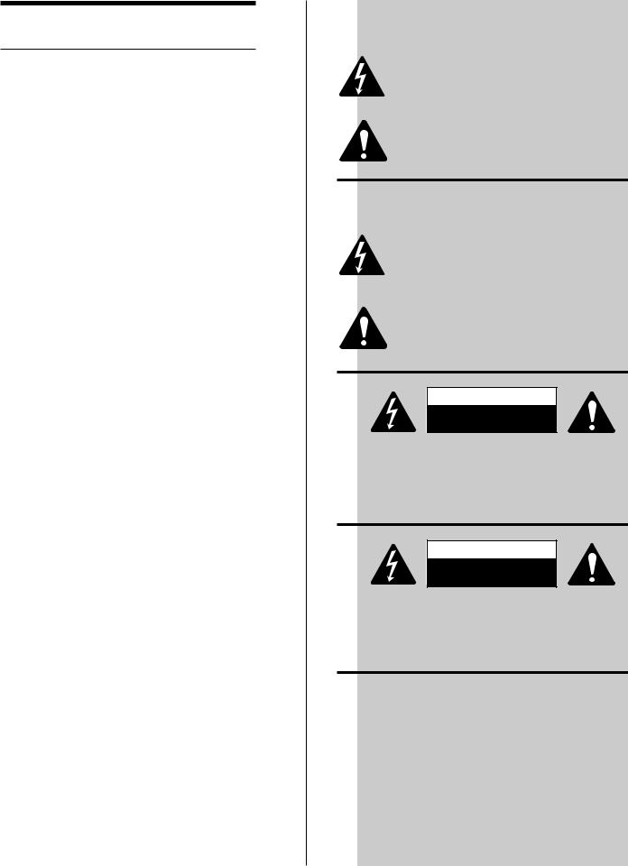
The lightning flash with arrowhead symbol, within an equilateral triangle, is intended to alert the user to the presence of uninsulated “dangerous voltage” within the product’s enclosure that may be of sufficient magnitude to constitute a risk of electric shock to humans.
The exclamation point within an equilateral triangle is intended to alert the users to the presence of important operating and maintenance (servicing) instructions in the literature accompanying the product.
EXPLICATION DES
SYMBOLES GRAPHIQUES
Le symbole èclair avec point de flèche à l’intrérieur d’un triangle équilatéral est utilisé pour alerter l’utilisateur de la présence à l’intérieur du coffret de “voltage dangereux” non isolé d’ampleur suffisante pour constituer un risque d’elétrocution.
Le point d’exclamation à l’intérieur d’un triangle équilatéral est employé pour alerter les utilisateurs de la présence d’instructions importantes pour le fonctionnement et l’entretien (service) dans le livret d’instruction accompagnant l’appareil.
CAUTION
RISK OF ELECTRIC SHOCK
DO NOT OPEN
CAUTION: To reduce the rish of electric shock, do not remove the cover. No user-serviceable parts inside. Refer servicing to qualified service personnel.
WARNING: To prevent fire or electric shock, do not expose this equipment to rain or moisture.
AVIS
RISQUE DE CHOCK ELECTRIQUE
NE PAS OUVRIR
ATTENTION: Pour enviter les risques de chock electrique, ne pas enlever le courvercle. Aucun entretien de pieces interieures par l’usager. Confier l’entretien au personnel qualifie.
AVIS: Pour enviter les risques d’incendie ou d’electrocution, n’exposez pas cet article a la pluie ou a l’humidite.
SAFEGUARDS
Electrical energy can perform many useful functions. This unit has been engineered and manufactured to assure your personal safety. Improper use can result in potential electrical shock or fire hazards. In order not to defeat the safeguards, observe the following instructions for its installation, use and servicing.
PRECAUTIONS
L’énergie électrique peut remplir de nombreuses fonctions utiles. Cet appariel a été conçu et réalisé pour assurer une sécurité personnelle entiére. Une utilisation impropre peut entraîner des risques d’électrocution ou d’incendie. Dans le but de ne pas rendre inutiles les mesures de sécurité, bien observer les instructions suivantes pour l’installation, l’utilisation et l’entretien de l’appareil.
2

I. INTRODUCTION
1.1 WELCOME
Thank you for selecting a QSC Series One power amplifier for your audio system. Our goal is to ensure your complete satisfaction with your amplifier purchase. Please do not hesitate to call your QSC Dealer or QSC Audio Products if you have any service problems or questions not answered in this manual.
Your QSC Series One power amplifier can be readily operated by anyone familiar with professional audio systems. The four models covered by this manual, the 1100, 1200, 1400 and 1700, have similar features and connections. Any differences will be covered in the following detailed instruction sections of this manual. Because not all amplifier features and characteristics are standardized, we recommend that both experienced and first-time users review the contents of this manual.
Please consult the table of contents for quick reference to sections of interest. We recommend that all users review the “Basic Instructions” section of this manual before installing or operating the amplifier.
1.2 WARRANTY AND DISCLAIMERS
QSC Audio Products, Inc. is not liable for any damage to speakers, amplifiers, or any other equipment that is caused by negligence or improper installation and/or use of the Series One Amplifier.
Product Warranty
QSC Audio Products, Inc. guarantees the Series One Amplifier to be free from defective material and/or workmanship for a period of three years from date of sale, and will replace defective parts and repair malfunctioning products under this warranty when the defect occurs under normal installation and use— provided the unit is returned to our factory via prepaid transportation with proof of purchase (sales receipt). This warranty provides that examination of the returned product must disclose, in our judgement, a manufacturing defect. This warranty does not extend to any product which has been subject to misuse, neglect, accident, improper installation, or where the date code has been removed or defaced.
Warranty and Service Repair Instructions
1.Pack the product safely making sure to include a copy of the sales receipt, your name, return address, and phone number. Mark the package: Attention Service Department.
2.Call QSC’s Service Department— 1-800-772-2834— and obtain a “Return Authorization” (R.A.) number.Ship the product prepaid to QSC Audio Products. We recommend UPS.
3.We will determine if the product is under warranty:
a.If it is, we will repair and ship it back to you at no charge.
b.If it is not, we will contact you and inform you of the charges. Upon your approval, we will repair the product and ship it back freight and services charges collect (COD).
1.3OVERVIEW OF AMPLIFIER
The basic Series One circuit design is the result of years of QSC product development, combined with a host of new features, a number of circuit improvements, and the use of premium components. The result is superb audio performance, exceptional reliability, and a flexible interface system.
To begin with, each channel has a balanced bipolar power supply which assures proper dynamic response during program peaks. We then combine a superior series of complementary power transistors with a modern high-performance integrated circuit at the input, in order to deliver the required power with the minimum number of amplifying stages. This ensures minimum signal degradation with maximum reliability and consistency. The circuit accepts balanced or unbalanced input signals and provides the high internal gain needed for low overall distortion and wide frequency response. Due to the circuit simplicity and the fact that we can use direct-mounted output transistors, Series One power amplifiers offer higher power, smaller size and lower weight than older designs.
In order to ensure that users get the full benefit of high performance amplification despite real-world hazards, our circuit includes many operational and protective features. Complete protection is provided for open-circuit, short-circuit, and mismatched loads; the amplifier will shut down temporarily if it over-heats, and AC circuit breakers protect against excessive power levels. Our protection circuits are designed to ensure a minimum of false triggering and unwanted interruptions and except for the AC breaker, which replaces the usual AC fuse, all protection systems will reset
3
automatically as soon as safe operation is assured. An equally important muting circuit protects the loudspeakers from unexpected damage, by muting the amp during turn-on and turn-off and by blocking DC faults, whether caused by the amplifier or preceding components.
The front panel presents essential user information and is recessed to prevent damage. The green power indicator serves as a pilot light and individual red clip indicators monitor overall performance of each channel. The AC switch and circuit breaker are front mounted for convenience and quick resetting. Except for the Model 1100, the Gain controls and input programming switches have been placed on the back of the amplifier to protect them from damage, inadvertent adjustment, or tampering. The Gain controls, as well as a pair of headphone jacks, have been placed on the front panel of the Model 1100 to allow easy access in monitoring applications.
The amplifiers use a separate bipolar power supply for each channel, for minimum crosstalk, cross-distortion, and greater reliability. A single dual-secondary transformer feeds isolated, separately fused rectifiers and filter capacitors for each channel. Thus the remaining channel can keep running in case of breakdown.
In order to interface properly with a variety of pro-audio systems, we have included all of the popular input and speaker connectors. Balanced or unbalanced inputs can be made using XLR plugs, screw lugs to the barrier strip, or 1/4-inch phone plugs (ring-tip-sleeve for balanced inputs). Speaker connections are made with 5-way binding posts.
The steel chassis, of the 1200, 1400 and 1700, is a 14 gauge, single piece design with integral rack mounting ears. The 1100 chassis features single piece aluminum extrusions that form the sides of the chassis and feature integral rack mounting ears and heatsinks. The extra strength chassis and rugged mounting of internal parts contributes greatly to QSC’s reputation for reliability by protecting the circuitry from years of road abuse.
All of these points are more fully explained in the following Sections.
1.4 SPECIFICATIONS
1100 |
1200 |
1400 |
1700 |
OUTPUT POWER (per channel)
Both Channels Driven
8 ohms, 20-20 kHz, 0.1% THD
4 ohms, 20-20 kHz, 0.1% THD
Bridged-Mono Operation
8 ohms, 20-20 kHz, 0.1% THD
DYNAMIC HEADROOM dB 8 ohms
4 ohms
DISTORTION, THD @ 8 ohms 20-20 kHz, at rated power SMPTE-IM at rated power
FREQUENCY RESPONSE
DAMPING FACTOR @ 8 ohms
NOISE (A-weighted)
VOLTAGE GAIN, dB
SENSITIVITY, V RMS
(for rated power, 8-ohms)
INPUT IMPEDANCE
CROSSTALK
CONTROLS
INDICATORS
COOLING 4
50w |
100w |
200w |
325w |
70w |
150w |
300w |
500w |
140w |
300w |
600w |
1000w |
2.0 |
2.0 |
2.0 |
1.9 |
2.3 |
2.5 |
2.5 |
2.9 |
Less than 0.1%, 0.01% typical
Less than 0.025%
20-20 kHz, +0, -1.0 dB at 1 watt
Greater than 200
100 dB below rated power
26 |
29 |
32 |
34 |
1.0 |
1.0 |
1.0 |
1.0 |
10K unbalanced inverting
20K balanced or unbalanced non inverting
-70dB, 20-20 kHz
AC Switch, Circuit Breaker, Gain Knobs, Input Programming DIP Switches, and Bridging Switch
Power: Green LED |
Clip: Red LED |
|
||
Convection |
Convection |
2 speed fan |
2 speed fan |
|

AMPLIFIER PROTECTION |
Full Short Circuit, Open Circuit, Over-Temp, Ultrasonic and |
|
||
|
RF Protection. Stable into reactive or mismatched loads. |
|
||
SPEAKER PROTECTION |
DC Load Fault Protection |
|
|
|
|
3 Second Turn-on, Instant-off Muting |
|
|
|
COMPLEMENTARY OUTPUT DEVICES |
4 |
8 |
16 |
32 |
POWER SUPPLY |
Single Transformer with Independent Isolated Secondary Windings, Fault |
|||
|
Fuses, Rectifiers, and Filter Capacitors |
|
|
|
DIMENSIONS |
|
|
|
|
Faceplate Width |
Standard 19" Rack Mounting |
|
|
|
Faceplate Height |
1.75" |
5.25" |
5.25" |
7.0" |
Chassis Depth |
8.7" |
9.5" |
9.5" |
11.75" |
WEIGHT |
|
|
|
|
Shipping, Lbs |
15 |
28 |
37 |
57 |
Net, Lbs |
12 |
24 |
34 |
55 |
II: BASIC INSTRUCTIONS
2.1 UNPACKING AND INSPECTION
All QSC Series One amplifiers are fully tested and inspected before they leave the factory. Despite the protective carton and rugged amplifier design, it is possible for shipping abuse to damage the amplifier. Check for obvious carton damage while unpacking the unit. After removing the amp from the box, rotate it in all directions to check for loose parts inside.
Please save the carton for return shipment, if required. QSC does not warranty against damage caused by sending amplifiers back in the wrong carton.
If shipping damage is evident, notify the transportation company immediately. Only the consignee can file a claim with the carrier for shipping damage. QSC will cooperate fully in such an event. Be sure to save the carton for the shipper to inspect.
2.2 IMPORTANT PRECAUTIONS
2.21The power must be OFF when making any connections. If you connect plugs with the power on, especially in dry environments, static sparks or bad cables can cause pops or hums which can damage speakers.
2.22When first powering up the amp, have the amplifier Gain controls all the way off, in case of defective cables or hookups. Turn the Gain controls up gradually until normal operation is verified.
2.23Check the AC voltage printed on the serial number label to ensure your amplifier is properly configured for the AC voltage supplied in your area before connecting the AC plug.
CONNECTION TO A VOLTAGE SOURCE OTHER THAN THE ONE SPECIFIED WILL IMMEDIATELY DAMAGE THE AMP, AND VOIDS THE WARRANTY.
2.24Never connect the speaker terminals (red binding posts) for two channels together on any power amplifier. The two channels will fight each other and possibly fail. Do not connect the speaker ground terminals (black binding posts) to chassis or signal grounds, as the resultant ground loop could cause ultrasonic oscillations. In other words, keep all speaker wiring separate for each channel, and separate from input wiring.
2.25Do not remove the amplifier cover, as there are dangerous voltages inside. Do not expose to rain or moisture. Refer all servicing to qualified personnel. The warranty will be void if the amp is tampered with by non-QSC repair centers or personnel.
2.26The QSC Warranty does not cover tampering by unqualified personnel, or repairs made at non-QSC repair centers. Please call the factory for Service Center information and locations.
5
2.27High voltages can be present on the speaker terminals. Always connect speaker terminals with the power off, and use heavy gauge cable with no frayed strands or damaged insulation.
2.28Please be aware that power amplifiers have high power circuitry inside with potential for fire and shock hazard; never plug in a damaged amplifier until the condition of the internal insulation is checked. If a circuit breaker blows quickly when turning the amp on, the amplifier is defective and should not be restarted until the amplifier has been repaired. Failure to observe these precautions could lead to fire or shock hazard.
2.29Power amplifiers are inherently heavy and may become hot after use; provide adequate support and be careful how you hold the amplifier when handling it.
2.3 QUICK INSTRUCTIONS
2.31Stereo Operation These instructions cover the normal use of the amplifier in two-channel or stereo applications. See Section 3 for detailed installation instructions and special cases.
2.32AC Power Connect the AC cord to a standard GROUNDED outlet only. The amplifier will operate satisfactorily over a +/- 10% range of voltages, but full rated performance will be met only at the rated voltage. Failure to properly ground the amplifier may result in unwanted hum and noise and will create a potential shock hazard.
2.33Floating Chassis Ground There is no provision for lifting signal ground relative to chassis ground on Series One amplifiers. For safety reasons do not lift the ground pin on the AC cord. Electronic balanced inputs are provided for hum rejection. Use balanced input cables to avoid hum, interference and ground loops.
2.34Input Programming Switches 8-pole mini DIP switches are located on the rear panel— see the rear panel illustration for details. They come factory set for normal stereo operation (switches 1,2 and 7,8 up). See section 3.5 for other cases.
2.35Octal Socket For normal operation, nothing should be plugged into the octal socket. It comes from the factory with a protective label to prevent corrosion of the pins.
2.36Input Connections The input polarity is as follows:
1/4-inch plug: |
tip is “minus” or inverting input |
|
ring is “plus” or non-inverting input |
|
barrel is ground, as always |
XLR plug: |
pin 1 is ground, as always |
|
pin 2 is “plus” or non-inverting input |
|
pin 3 is “minus” or inverting input (AES Standard) |
Barrier Strip: |
“GND” is circuit ground |
|
“+” is “plus” or non-inverting input |
|
“-” is “minus” or inverting input |
When making unbalanced connections, the barrel of an ordinary two-wire 1/4 inch plug will ground the “plus” side of the balanced input; XLR plugs will need to have the unused pin grounded inside the plug, and the installer will need to ground the unused screw on the barrier strip. It is still possible to use the balanced inputs to reject hum with an unbalanced signal. See Section 3.3 for details.
2.37Speaker Connections Banana plugs, spade lugs, or bare wire ends can be connected to the 5-way binding posts. Be sure to observe correct polarity (red/black terminals) for each speaker to insure that all speakers move in the same direction.
The 1100 features a pair of standard 1/4" headphone jacks on the front panel. They are connected to the speaker outputs of the amplifier through a resistive pad that prevents excessive power levels from damaging the headphones.
2.38Power Up Start with the gain controls off until proper operation is verified. Upon turning on the switch, the power LED should come on green. After three seconds, the muting circuit should release and turn on the sound. The amp should now be working, and the Gain controls can be advanced. In case of difficulty consult Section 3.9.
6

2.39Operation and Indicators Note that the Gain controls are calibrated in dB. As you turn the Gain down, it takes more input signal to reach full power, so the Gain should be kept in the upper 12 dB of its range for full power output from normal signal sources. The “0 dB” reference indicates that the amplifier gain is at 26 dB when the knob is adjusted to this position.
Note that full amplifier output power may be achieved even if the gain controls are not turned fully up. However, a larger input signal will be required to produce full rated output.
LED (Light Emitting Diode) indicators monitor the operation of the amplifier. A green LED serves as the pilot light to indicate that power is on. Each channel has a red “Clip” indicator that will show any distortion in the amplifier. Upon power up, these may not flash symmetrically. This does not necessarily indicate that there may be a problem.
The muting circuit blocks the sound for three seconds after turn-on and immediately after turn-off. This prevents turn-on and turn-off thumps and transients from reaching the speakers.
Please refer to Section 3 for more detailed instructions.
1100 FRONT VIEW
AC BREAKER AC SWITCH |
HEADPHONE |
|
PILOT LIGHT JACKS |
GAIN CONTROLS |
CLIP INDICATORS
1100 BACK VIEW |
|
OCTAL SOCKET |
|
||||
|
|
||||||
BARRIER STRIP INPUTS |
|||||||
|
|||||||
|
|
|
|
|
|
|
|
|
|
|
|
|
|
|
|
|
|
|
|
|
|
|
|
|
|
|
|
|
|
|
|
|
|
|
|
|
|
|
|
|
|
|
|
|
|
|
|
|
|
INPUT |
|
|
|
||
|
|
|
AC CORD |
||||
|
PROGRAMMING |
|
|||||
|
|
SPEAKER |
|||||
|
|
SWITCHES |
|
||||
|
|
|
|
|
|
BINDING POSTS |
|
|
|
|
|
|
|
|
|
1/4 INCH INPUTS |
|
|
|||||
|
|
|
|
|
|
|
|
|
|
XLR INPUT |
|
|
|
|
|
|
|
|
|
|
|||
|
|
|
|
|
|
|
|
7
 Loading...