

Page 1
INSTALLATION & MAINTENANCE INSTRUCTIONS
01-2016
ED
6100-LED
1
Page 2

SAFETY AND PROPER USAGE
To ensure safe and enduring performance of this product, you must comply strictly with the instructions enclosed herein.
Non-compliance with instructions or improper handling of the product will void your warranty! Usage of this product in
conditions not specified in this manual or in contrary to the instructions hereby provided is considered IMPROPER. The
manufacturer will not be held liable for any damages resulting from improper use of the product.
SAFETY & WARNING INSTRUCTIONS
- Observe valid and generally accepted safety rules when planning, installing and using this product.
- Take proper measures to prevent unintentional operation of the product or damage to it.
- Do not attempt to disassemble this product or lines in the system while they are under pressure.
- Always depressurise the compressed air system before working on the system.
It is important that personnel use safe working practices and observe all regulations and legal requirements for safety
when operating this product. When handling, operating or carrying out maintenance on this product, personnel must
employ safe engineering practices and observe all local health & safety requirements & regulations. International users
refer to regulations that prevail within the country of installation. Most accidents, which occur during the operation and
maintenance of machinery, are the result of failure to observe basic safety rules or precautions. An accident can often be
avoided by recognising a situation that is potentially dangerous. Improper operation or maintenance of this product could
be dangerous and result in an accident causing injury or death. The manufacturer cannot anticipate every possible
circumstance, which may represent a potential hazard. The WARNINGS in this manual cover the most common potential
hazards and are therefore not all-inclusive. If the user employs an operating procedure, an item of equipment or a method
of working which is not specifically recommended by the manufacturer he must ensure that the product will not be
damaged or made unsafe and that there is no risk to persons or property.
NEVER REPLACE ORIGINAL COMPONENTS WITH ALTERNATIVES
2
Page 3

INSTALLATION INSTRUCTIONS
Before installing this product, make sure it complies with your request and that it suits your application!
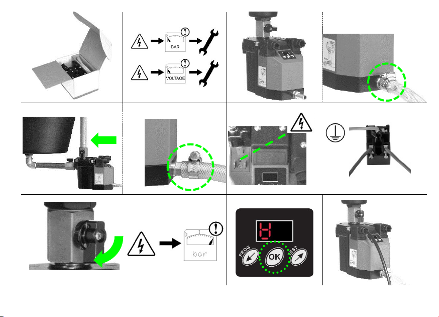
1.1 Unpack the unit and visually inspect for any transport damage incurred after leaving our factory.
1.2 Depressurise the system before installation or maintenance is carried out!
1.3a Top inlet connection: If you choose to use the top inlet, locate a suitable condensate draining point in your
compressed air system and connect your drain as illustrated. The use of a ball valve is advisable.
1.3b Top inlet connection: Connect the outlet to an Oil/Water-Separator. We advise to use the nipple supplied with your
drain. If it is necessary to use an alternative nipple, make sure it is of the correct thread (1/4” BSP). Do not over tighten!
1.4a Side inlet connection: If you choose to use the side inlet, locate a suitable condensate draining point in your
compressed air system and connect your drain as illustrated.
The use of a ball valve is advisable. The use of a venting line may be required.
1.4b Side inlet connection: Connect the outlet to an Oil/Water separator. We advise to use the nipple supplied with your
drain. If it is necessary to use an alternative nipple, make sure it is of the correct thread (1/4” BSP). Do not over tighten!
1.5 Power cable connection: Unscrew the connector screw and remove the cap from the connector to connect your
power cable as illustrated. Replace the power connector, tighten the connector screw (Max. torque 1Nm) and turn on
the power supply.
Make sure the gasket is secured properly to ensure IP65 rating.
1.6 Slowly open the ball valve to restore normal system pressure.
1.7 Press and hold down the TEST button to check the valve function.
A purging sound must be heard.
1.8 Your drain is ready for operation! See page 8-10 for programming instructions.
Note: We advise to check this product at least once a year and replace serviceable parts when necessary.
Note: Clean the strainer periodically to avoid possible blocking causes by rust and/or debris.
Note: Check the valve function periodically. A purging sound must be heard.
3
Page 4
1.1 1.2 1.3a 1.3b
1.4a 1.4b 1.5
1.6 1.7 1.8
L N
4
Page 5
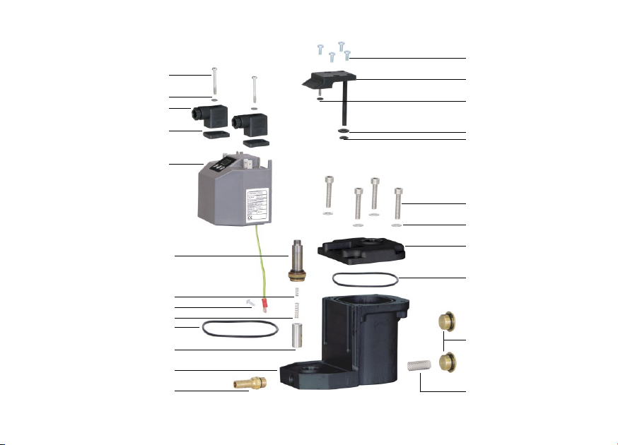
Valve shaft
Valve spring small
Screw
Valve spring large
Electronics compartment gasket
Valve plunger
Housing bottom part
Outlet nipple
Connector screw (2x)
Screw gasket (2x)
Connector (2x)
Connector gasket (2x)
Electronics compartment
(with attached Earth cable)
Sensor module screw (4x)
Sensor module
Sensor module O-ring small
Sensor module O-ring large
Sensor module O-ring middle
Housing bolt (4x)
Housing bolt Washer (4x)
Housing top part
Housing gasket
Inlet plug (2x)
Strainer
5
Page 6

ALARM INSTALLATION INSTRUCTIONS
The drain is equipped with an alarm feature. Alarm occurs
when the valve has to open too many (>100) consecutive times
without a pause. The reason for this may be debris (rust)
particles blocking the valve, outlet, or a sensor failure indicating
a service necessity. It could also mean that your drain receives
more condensate than it can handle. The alarm feature can be
connected to an external alarm device with its own power
supply.
1. Unscrew the connector screw and remove the cap from the
alarm connector to connect the alarm cables to the connector
as shown below. Caution is required as you may be working
with hazardous voltages!
2. Connect the cable to your alarm device, any device of your
choice can be applied i.e. a (flashing) light or alarm panel.
3. Connect your alarm device to a power supply. The alarm
switch type is a ‘contact output switch’. An external power
supply is required as the alarm connection point on the drain
works like a relay switch only.
4. Connect the power supply to the drain alarm connector to
close the circle. Replace the connector and tighten the
connector screw (Max. torque 1Nm). Make sure the gasket is
secured properly to ensure IP65 rating.
6
Page 7

ADDITIONAL INSTALLATION INSTRUCTIONS
Avoid water pockets when installing the
feed pipe, this will create an air lock.
If the downwards slope of the feed pipe is not
sufficient, or if any other flow problem occurs,
a venting line must be installed to prevent an
air lock.
Do not narrow the feed pipe when
installing additional adapters or piping,
these may cause air locks.
The feed pipe must be horizontal or
ideally at a downwards slope (>1°).
We advise to apply a 1/2" pipe diameter
and 1/2" elbows to avoid an air lock.
7
Page 8

DISPLAY
SYMBOL
MEANING
ACTION TO BE TAKEN
Normal operation, condensate has not reached the discharge level.
None Discharge level has been reached, valve is opened to discharge the condensate.
None
S Flashing
Service interval reached.
Unit will operated normally, but it is time to clean/service the unit. The alarm
output has been activated.
Clean/service the unit.
After the unit has been serviced,
enter the CL mode to reset the
service warning.
AC Flashing
Alarm cycle and alarm output activated.
The unit has purged more than the ‘AC set value’ times without pause. Unit
works as normal.
Check why the alarm cycle has been
activated and reset by pressing the
button.
At Flashing
Alarm cycle and alarm output activated.
The unit has purged more than the ‘AC set value’ times in ‘At set value’ hours.
Unit works as normal.
Check why the alarm cycle has been
activated and reset by pressing the
button.
Cleaning Mode. Press + for 5 seconds to enter Cleaning Mode.
Sensing is disabled, press to open the valve and to flush the unit.
Clean the unit and/or press to
restore to normal operation.
8
Page 9

PROGRAMMING INSTRUCTIONS
Press the button for at least 10 seconds to enter the menu. You can move through the menu by pressing the
or buttons. When you have reached the required menu option, press the button to enter the sub-menu. In
The sub-menu you can change the default setting by pressing or buttons. After you have changed the default
setting, simply press the button to save the change. Wait for at least 10 seconds (without pressing any button) to
exit the complete menu structure.
SYMBOL
MEANING
ACTION TO BE TAKEN
Default Settings.
Resets all settings to factory settings.
Press the button to select.
Anti-Air lock setting.
Each X hours the unit will purge, regardless of the condensate level.
Use the or buttons to
choose 1-99 hours.
0 = disabled, 8 = default
Purge time setting.
When the condensate level has reached a pre-defined level, the unit will purge
and open the valve for X seconds.
Use the or buttons to
choose 0.1-0.9 seconds.
0.3 = default
Alarm Cycle setting.
When the unit purges more than X consecutively times without pause, this
could mean that an illogical amount of condensate is being discharged. The
alarm output is activated.
Use the or buttons to
choose 1-99 times.
0 = disabled, 0 = default
9
Page 10

SYMBOL
MEANING
ACTION TO BE TAKEN
Alarm time cycle setting.
If the unit purges more than X (X amount set in AC) times in X hours, this could
mean that an illogical amount of condensate is being discharged in a period of X
hours. The alarm output is activated.
Use the or buttons to
choose 1-99 hours.
0 = disabled, 0 = default
Alarm Output setting.
The unit can be programmed to have a NO (Normally Open) or a NC (Normally
Closed) alarm relay output.
Use the or buttons to
choose NO or NC contacts.
NC = default
DO NOT CHANGE
1 = default
Sensing time setting.
When the condensate has reached a pre-defined level, the unit will wait for X
seconds of continuous detection before purging and opening the valve for X
(set in Pt) seconds.
Use the or buttons to
choose 0.1-9.9 seconds.
1 = default
Service Interval setting.
The unit will remind you every X weeks that it is time to clean or service the
unit.
Note: each time the power is switched off, the unit will add 1 week to its count
memory.
Use the or buttons to
choose 1-99 weeks.
0 = disabled, 0 = default
10
Page 11

CLEANING INSTRUCTIONS
IMPORTANT NOTICE!
These instructions are for cleaning the drain. If your drain requires maintenance, i.e. replacement of wearing components,
please refer to our dedicated maintenance instructions (supplied with the service kit).
2.1 Stop the condensate supply, i.e. close the ball valve which is installed in front of the drain.
2.2 Press the TEST button to empty the drain of any residual condensate and to depressurise the drain.
2.3 Switch off the power supply and remove the power connector by unscrewing the connector screw.
Make sure the display is off to check if the power supply is successfully disconnected.
2.4 Open the housing by unscrewing the four housing bolts using a 5mm Allen key and remove the top part from the reservoir.
2.5 Slide the electronics compartment up and unscrew the valve from the bottom part of the housing using a 23mm wrench.
WARNING: make sure the electronics compartment does not get wet, this will damage the unit!
2.6 Clean all valve parts thoroughly. Make sure there’s no debris left in the other parts of the drain.
2.7 Use a 10mm Allen key to remove the plug and strainer. Clean the strainer thoroughly.
Replace the strainer and plug, using a 10mm Allen key.
2.8 Reassemble the valve inner parts and screw the valve back in to the bottom part of the housing, using a 23mm wrench (Max. torque 10Nm).
2.9 Close the housing by replacing the electronics compartment and top part on the reservoir and fixing the 4 housing bolts (Max. torque 6Nm). Make
sure the gaskets are secured properly to ensure IP65 rating and make sure the electronics have not been in contact with water.
WARNING: make sure the cable connected to the electronics compartment does not get damaged while re -assembling the components!
2.10 Replace the power connector, tighten the connector screw (Max. torque 1Nm) and turn on the power supply.
Make sure the gasket is secured properly to ensure IP65 rating.
Make sure the display lights up to check if the power supply is successfully connected.
2.11 Slowly open the ball valve to restore the condensate supply.
2.12 Press and hold down the TEST button to check the valve function.
Your drain is ready for operation!
Depressurise the system before installation
or maintenance is carried out!
11
Page 12

2.1 2.2 2.3 2.4
2.5 2.6 2.7 2.8
2.9 2.10 2.11 2.12
12
Page 13

TECHNICAL SPECIFICATIONS
Max. compressor capacity
100 m³/min.
3500 cfm.
Min. / Max. system pressure
0 Bar / 16 Bar
0 Psi / 230 Psi
Min. / Max. medium temperature
1 °C / 50 °C
34 °F / 122 °F
Valve type
2/2 way, direct acting
Valve orifice
4 mm
0,157”
Inlet connection + height
1/2" BSP or NPT, 11 cm (top) and 7.5 & 1.5 cm (side)
1/2" BSP or NPT, 4.3” (top) and 2.9” & 0.6” (side)
Outlet connection + height
1/4" BSP, 1.5 cm (side)
1/4" BSP, 0.6” (side)
Valve seals
FPM
Supply voltage options
230VAC or 115VAC or 24VAC or 24VDC (See label on unit!)
Connectors
DIN 43650-B
Serviceable valve
Yes
TEST feature
Yes
Environmental protection
IP65 (NEMA4)
Integrated mesh strainer
Yes
Alarm feature type
NO = Normally open contacts, closed when in alarm phase.
NC = Normally closed contacts, open when in alarm phase.
13
Page 14

SERVICE CHART
Date
Description
Name
14
Page 15

DIMENSIONS (mm)
15
 Loading...