

Page 1
PLX8x-EIP-61850
Communication Gateway
EtherNet/IP™ Server to
IEC 61850 Client
July 2, 2015
USER MANUAL
Page 2

Your Feedback Please
We always want you to feel that you made the right decision to use our products. If you have suggestions, comments,
compliments or complaints about our products, documentation, or support, please write or call us.
How to Contact Us
ProSoft Technology
5201 Truxtun Ave., 3rd Floor
Bakersfield, CA 93309
+1 (661) 716-5100
+1 (661) 716-5101 (Fax)
www.prosoft-technology.com
support@prosoft-technology.com
Copyright © 2015 ProSoft Technology, Inc. All Rights Reserved.
PLX81-EIP-61850, PLX82-EIP-61850
July 2, 2015
ProSoft Technology ® is a registered trademark of ProSoft Technology, Inc. CompactLogix is a trademark of Rockwell
Automation, Inc., registered in the United States and certain other countries. ControlLogix, MicroLogix, and RSLogix
are trademarks of Rockwell Automation, inc. Ethernet/IP is a trademark of the Open Device Vendors Association. All
other brand or product names are or may be trademarks of, and are used to identify products and services of, their
respective owners.
In an effort to conserve paper, ProSoft Technology no longer includes printed manuals with our product shipments.
User Manuals, Datasheets, Sample Ladder Files, and Configuration Files are provided on the enclosed DVD, and are
available for digital download from our web site, http://www.prosoft-technology.com at no charge.
Content Disclaimer
This documentation is not intended as a substitute for and is not to be used for determining suitability or reliability of
these products for specific user applications. It is the duty of any such user or integrator to perform the appropriate
and complete risk analysis, evaluation and testing of the products with respect to the relevant specific application or
use thereof. Neither ProSoft Technology nor any of its affiliates or subsidiaries shall be responsible or liable for
misuse of the information contained herein. Information in this document including illustrations, specifications and
dimensions may contain technical inaccuracies or typographical errors. ProSoft Technology makes no warranty or
representation as to its accuracy and assumes no liability for and reserves the right to correct such inaccuracies or
errors at any time without notice. If you have any suggestions for improvements or amendments or have found errors
in this publication, please notify us.
No part of this document may be reproduced in any form or by any means, electronic or mechanical, including
photocopying, without express written permission of ProSoft Technology. All pertinent state, regional, and local safety
regulations must be observed when installing and using this product. For reasons of safety and to help ensure
compliance with documented system data, only the manufacturer should perform repairs to components. When
devices are used for applications with technical safety requirements, the relevant instructions must be followed.
Failure to use ProSoft Technology software or approved software with our hardware products may result in injury,
harm, or improper operating results. Failure to observe this information can result in injury or equipment damage.
© 2015 ProSoft Technology. All Rights Reserved.
Printed documentation is available for purchase. Contact ProSoft Technology for pricing and availability.
North America: +1.661.716.5100
Asia Pacific: +603.7724.2080
Europe, Middle East, Africa: +33 (0) 5.3436.87.20
Latin America: +1.281.298.9109
Page 3

ATEX
CSA-CB Safety
CE
GOST-R
UL/cUL
Important Safety Information
Power, Input, and Output (I/O) wiring must be in accordance with Class I, Division 2 wiring methods, Article 501-4 (b)
of the National Electrical Code, NFPA 70 for installation in the U.S., or as specified in Section 18-1J2 of the Canadian
Electrical Code for installations in Canada, and in accordance with the authority having jurisdiction. The following
warnings must be heeded:
North America Warnings
A Warning - Explosion Hazard - Substitution of components may impair suitability for Class I, Division 2.
B Warning - Explosion Hazard - When in Hazardous Locations, turn off power before replacing or rewiring
modules.
C Warning - Explosion Hazard - Do not disconnect equipment unless power has been switched off or the area is
known to be nonhazardous.
Agency Approvals & Certifications
Page 4

Page 5

PLX8x-EIP-61850 ♦ Communication Gateway Contents
Server to
IEC 61850 Client User Manual
Contents
Your Feedback Please ........................................................................................................................ 2
How to Contact Us .............................................................................................................................. 2
Important Safety Information ............................................................................................................... 3
Agency Approvals & Certifications ...................................................................................................... 3
1 Start Here 9
1.1 Overview.................................................................................................................... 9
1.2 System Requirements ............................................................................................. 10
1.3 Package Contents ................................................................................................... 10
1.4 Setting Jumpers ...................................................................................................... 11
1.4.1 PLX81-EIP-61850 ................................................................................................... 11
1.4.2 PLX82-EIP-61850 ................................................................................................... 12
1.5 Mounting the Gateway on a DIN-rail ....................................................................... 12
1.6 Connecting Power to the Unit ................................................................................. 13
1.7 Installing the ProSoft Software ................................................................................ 14
1.7.1 Installing the ProSoft Discovery Service ................................................................. 14
1.7.2 Installing the ProSoft EIP-61850 Configuration Manager ....................................... 14
1.7.3 Installing the ProSoft EIP-61850 Tag Monitor ......................................................... 14
2 Configuring the PLX8x-EIP-61850 Gateway 15
2.1 Connecting Your PC to the Gateway ...................................................................... 15
2.2 Setting a Temporary IP Address in the Gateway .................................................... 16
2.3 Creating a New Project in the Configuration Manager ............................................ 17
2.4 Exporting a Project from the Configuration Manager .............................................. 18
2.5 Importing a Project into the Configuration Manager ............................................... 19
2.6 Configuring the Gateway EtherNet/IP Adapter ....................................................... 19
2.7 Adding EtherNet/IP Device...................................................................................... 21
2.8 Importing IEDs Files ................................................................................................ 21
2.9 Creating the IED Network........................................................................................ 24
2.10 Mapping Data Attributes from IEDs to the Gateway ............................................... 25
2.10.1 Mapping MMS Messages ........................................................................................ 26
2.10.2 Mapping Reports ..................................................................................................... 29
2.10.3 Mapping GOOSE Messages ................................................................................... 31
2.10.4 Deleting one or more IEC 61850 mappings ............................................................ 33
2.11 Mapping Tags in the Gateway to EtherNet/IP ......................................................... 34
2.12 Validating the Configuration .................................................................................... 37
2.13 Downloading the Configuration File to the Gateway ............................................... 38
2.14 Uploading the Configuration from the Gateway ...................................................... 39
2.15 Exporting the IED Add-On Instructions for RSLogix 5000 ...................................... 40
2.16 Exporting the EIP-61850 Configuration to a File ..................................................... 40
2.17 Importing an Updated IED File ................................................................................ 41
3 Adding the Gateway to RSLogix 5000 43
3.1 Create or open a project in RSLogix 5000 .............................................................. 43
3.2 Add the Communications modules and connection ................................................ 44
3.3 Add the Gateway ..................................................................................................... 46
ProSoft Technology, Inc. Page 5 of 167
July 2, 2015
Page 6

Contents PLX8x-EIP-61850 ♦ Communication Gateway
User Manual Server to
IEC 61850 Client
3.4 Download the project to the processor to verify the connection ............................. 50
3.5 Import the AOI from the Configuration Manager .................................................... 51
3.6 Add the AOI to a New Ladder Rung in RSLogix 5000 ........................................... 52
3.7 Map to the Generic Ethernet bridge........................................................................ 54
3.8 Importing an updated AOI from an updated IED .................................................... 56
4 Diagnostics and Troubleshooting 57
4.1 Known Anomalies ................................................................................................... 57
4.2 Important Design Considerations ........................................................................... 57
4.3 Driver Status Data .................................................................................................. 58
4.3.1 Status values .......................................................................................................... 60
4.4 Rebooting the Gateway .......................................................................................... 60
4.5 ProSoft EIP-61850 Tag Monitor Diagnostics .......................................................... 61
4.6 ProSoft ProSoft 61850 Configuration Manager Diagnostics .................................. 62
4.6.1 IEC 61850 Client Diagnostics ................................................................................. 62
4.6.2 MCP Diagnostics .................................................................................................... 66
4.6.3 EtherNet/IP Diagnostics .......................................................................................... 69
4.6.4 SNTP/NTP .............................................................................................................. 71
4.7 Web Service and Gateway Web Page ................................................................... 72
4.8 Event Logger........................................................................................................... 73
4.8.1 61850C Events ....................................................................................................... 75
4.8.2 EIPS Events ............................................................................................................ 75
4.8.3 MCP Events ............................................................................................................ 76
4.8.4 MCP Interface Events ............................................................................................. 76
4.8.5 SNTP/NTP Events .................................................................................................. 76
4.8.6 InterProcess Communication (IPC) Events ............................................................ 77
4.9 Gateway Troubleshooting ....................................................................................... 77
5 Reference 79
5.1 Functional Specifications ........................................................................................ 79
5.1.1 Specifications .......................................................................................................... 79
5.1.2 Specifications - EtherNet/IP .................................................................................... 80
5.1.3 Specifications - IEC 61850 Client ........................................................................... 82
5.1.4 Specifications - SNTP/NTP Client .......................................................................... 82
5.2 Hardware Specifications PLX8x-EIP-61850 ........................................................... 83
5.3 LEDs ....................................................................................................................... 83
5.4 Gateway .................................................................................................................. 84
5.4.1 Asynchronous Processes ....................................................................................... 84
5.4.2 Tag Database ......................................................................................................... 85
5.4.3 SNTP/NTP .............................................................................................................. 86
5.5 IEC 61850 Detailed Specifications ......................................................................... 87
5.5.1 Application Association Model ................................................................................ 87
5.5.2 DATA-SET .............................................................................................................. 89
5.5.3 Report Control Block ............................................................................................... 90
5.5.4 GOOSE Control Block ............................................................................................ 94
5.5.5 Control .................................................................................................................... 96
5.5.6 MMS ...................................................................................................................... 101
5.5.7 EtherNet/IP Adapter .............................................................................................. 105
5.5.8 IEC 61850 Client ................................................................................................... 106
5.6 IEC 61850 Standard Introduction ......................................................................... 107
Page 6 of 167 ProSoft Technology, Inc.
July 2, 2015
Page 7

PLX8x-EIP-61850 ♦ Communication Gateway Contents
Server to
IEC 61850 Client User Manual
5.6.1 Integrating the Substation ..................................................................................... 107
5.6.2 IEC 61850 Benefits ............................................................................................... 109
5.6.3 IEC 61850 Communication Features .................................................................... 109
5.6.4 SCL / Standardized Data Exchange ..................................................................... 109
5.6.5 Additional Advantages to Substation Configuration Description Language (SCL)110
5.6.6 Report Control Block BRCB (Clause 14) .............................................................. 112
5.6.7 GSE (Clause 15) ................................................................................................... 112
5.6.8 Control (Clause 17) ............................................................................................... 112
5.6.9 Time and Time Synchronization (Clause 18) ........................................................ 119
5.6.10 Naming Conventions (Clause 19) ......................................................................... 119
5.7 Usage Examples ................................................................................................... 120
5.7.1 Rockwell Automation PLC Device Configuration .................................................. 120
5.7.2 Example: Energy Application: ............................................................................... 122
5.7.3 Example: Oil & Gas Application ............................................................................ 123
5.7.4 Monitoring .............................................................................................................. 124
5.7.5 Measuring and Metering........................................................................................ 124
5.7.6 Supervision and Protection ................................................................................... 125
6 Support, Service and Warranty 127
6.1 Contacting Technical Support ............................................................................... 127
6.2 Warranty Information ............................................................................................. 128
List of Abbreviations 129
Glossary of Terms 145
Index 165
ProSoft Technology, Inc. Page 7 of 167
July 2, 2015
Page 8

Contents PLX8x-EIP-61850 ♦ Communication Gateway
User Manual Server to
IEC 61850 Client
Page 8 of 167 ProSoft Technology, Inc.
July 2, 2015
Page 9

PLX8x-EIP-61850 ♦ Communication Gateway Start Here
In this Chapter
Overview ................................................................................................. 9
System Requirements ........................................................................... 10
Package Contents ................................................................................. 10
Setting Jumpers .................................................................................... 11
Mounting the Gateway on a DIN-rail ..................................................... 12
Connecting Power to the Unit ................................................................ 13
Installing the ProSoft Software .............................................................. 14
Server to
IEC 61850 Client User Manual
1 Start Here
€
1.1 Overview
This User Manual explains the features of the PLX8x-EIP-61850 EtherNet/IP to
IEC 61850 gateway. It guides you through configuring the gateway, showing how
to map IEC 61850 Data Attributes between an Intelligent Electronic Device (IED),
through the gateway, and a Rockwell Automation® ControlLogix® or
CompactLogix™ (PLC). The configuration software creates files to import into
RSLogix™ 5000 programming software, integrating the gateway into your
system.
This User Manual provides examples of how to move IEC 61850 Data Attributes
using IEC 61850 8.1 MMS messages. The PLC reads and write data to the IED.
The gateway uses Class 1 EtherNet/IP I/O messaging to exchange data from the
IEDs to the Logix processor. You need to have an Intelligent Electronic Device
(IED) and be familiar with it.
IEDs generally come with their own configuration software, and a template IED
Capability Description (ICD) file. The template file represents a device that is not
configured. Once configured, the device makes a Configured IED Description
(CID) file. Some devices can also make a System Configuration Description
(SCD) file. Some IEDs generate an ICD file (rather than a CID file) for their
configured file, so be sure to have the right file. Please have these files on hand
before beginning this process.
For a complete list of features and supported functions of the PLX8x-EIP-61850
gateway, refer to the IEC 61850 PICS Statement, which is available as a
separate download at http://www.prosoft-technology.com.
ProSoft Technology, Inc. Page 9 of 167
July 2, 2015
Page 10

Start Here PLX8x-EIP-61850 ♦ Communication Gateway
Qty.
Part Name
Part Number
Part Description
1
EtherNet/IP to IEC
61850 gateway
PLX8x-EIP-61850
ProLinx communication gateway
1
Ethernet Cable
RL-CBL025
5-foot straight-through Ethernet cable
1
Screwdriver
HRD250
Small, flat-bladed screwdriver
1
ProSoft Solutions DVD
DVD-001
Contains utilities and documentation for the
PLX8x-EIP-61850 gateway
1
1 GB Industrial SD
Card
SDCard-1GB
Industrial SD card for stored gateway
configuration
1
Power Connector
J180
3-wire DC power connector
User Manual Server to
IEC 61850 Client
1.2 System Requirements
The ProSoft ProSoft 61850 Configuration Manager configuration software for the
PLX8x-EIP-61850 gateway requires the following minimum hardware and
software components:
Pentium® II 450 MHz minimum. Pentium III 733 MHz (or better)
recommended
128 Mbytes of RAM minimum, 256 Mbytes of RAM recommended
100 Mbytes of free hard disk space (or more based on application
requirements)
256-color VGA graphics adapter, 800 x 600 minimum resolution (True Color
1024 x 768 recommended)
DVD drive
Supported operating systems:
Microsoft Windows 7 (32 bit) (64bit not tested)
Microsoft Windows Vista (not tested)
Microsoft Windows XP Professional with Service Pack 1 or 2
Microsoft Windows 2000 Professional with Service Pack 1, 2, or 3 (not
tested)
Microsoft Windows Server 2003 (not tested)
1.3 Package Contents
The following components are included with your PLX8x-EIP-61850 gateway,
and are all required for installation and configuration.
Important: Before beginning the installation, verify that all of the following items
are present.
If any of these components are missing, please contact ProSoft Technology
Technical Support for replacement parts.
Page 10 of 167 ProSoft Technology, Inc.
July 2, 2015
Page 11
PLX8x-EIP-61850 ♦ Communication Gateway Start Here
Server to
IEC 61850 Client User Manual
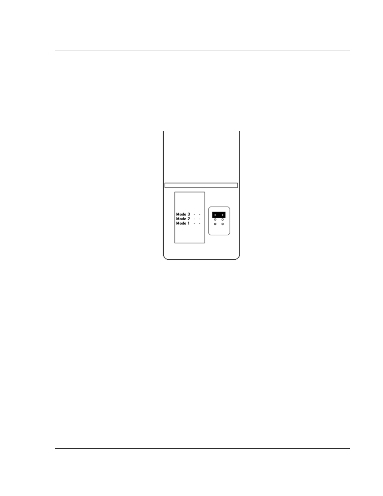
1.4 Setting Jumpers
Jumper settings are located on the back of the module.
1.4.1 PLX81-EIP-61850
When the module is manufactured, the port selection jumpers are set to Mode 3.
You must set the jumpers to the correct position. The following diagram of the
back of the module describes the jumper settings.
Mode 3:
Setup Jumper: This is the top jumper. This must be jumpered when performing a
firmware upgrade or when downloading a configuration file to the module. For
normal operation, this jumper should be hung on only one pin (not jumpered).
Removing the jumper allows for better communications between the IEC and
EtherNet/IP driver and the jumper should be removed during running conditions.
Mode 2:
Default IP Jumper: This is the middle jumper. The default IP address of the
gateway is 192.168.0.250. Set this jumper to set the gateway's IP address back
to the default. For normal operation, this jumper should be hung on only one pin
(not jumpered).
Mode 1:
Reserved Jumper: This is the bottom jumper. It is reserved for internal ProSoft
Technology use only. For normal operation, this jumper should be hung on only
one pin (not jumpered).
ProSoft Technology, Inc. Page 11 of 167
July 2, 2015
Page 12
Start Here PLX8x-EIP-61850 ♦ Communication Gateway
User Manual Server to
IEC 61850 Client
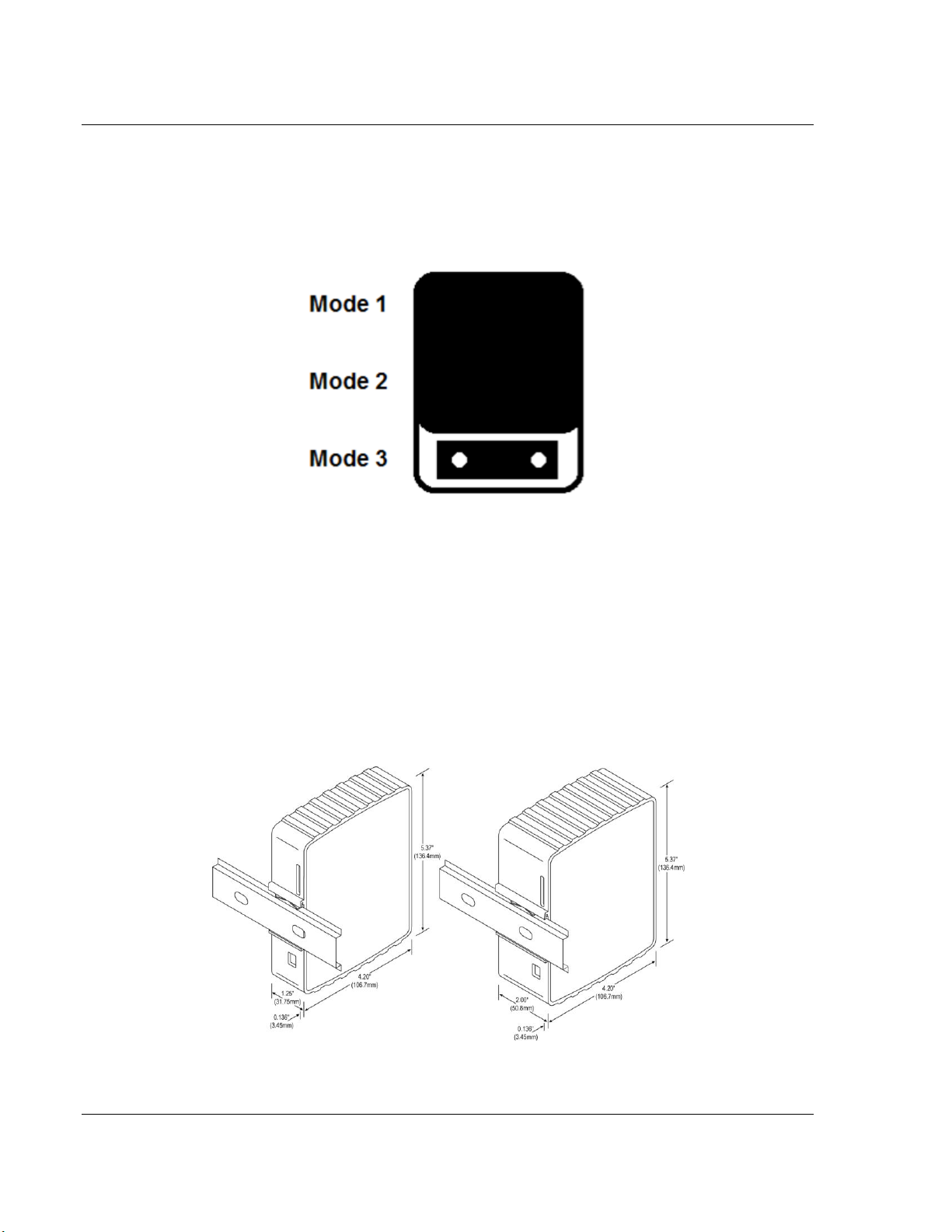
1.4.2 PLX82-EIP-61850
For security reasons, the Mode 1 and Mode 2 jumpers are not readily accessible.
Under normal conditions, these two jumpers will not be needed. The following
diagram illustrates the available Setup Jumper setting.
Setup Jumper:
This mode is jumpered by default. It must be jumpered when performing a
firmware upgrade or when downloading a configuration file to the module.
For normal operation, this jumper should be hung on only one pin (not jumpered).
Removing the jumper allows for better communications between the IEC and
EtherNet/IP driver.
1.5 Mounting the Gateway on a DIN-rail
Page 12 of 167 ProSoft Technology, Inc.
July 2, 2015
Page 13
PLX8x-EIP-61850 ♦ Communication Gateway Start Here
Server to
IEC 61850 Client User Manual
To mount the ProLinx IEC 61850 Series gateway module on a DIN-rail, follow
these steps.
1 Position the gateway module on the DIN-rail B at a slight angle.
2 Hook the lip on the rear of the adapter onto the top of the DIN-rail, and rotate
the adapter onto the rail.
3 Press the adapter down onto the DIN-rail until flush. The locking tab snaps
into position and lock the module to the DIN-rail.
4 If the adapter does not lock in place, use a screwdriver or similar device to
move the locking tab down while pressing the adapter flush onto the DIN-rail
and release the locking tab to lock the adapter in place. If necessary, push up
on the locking tab to lock.
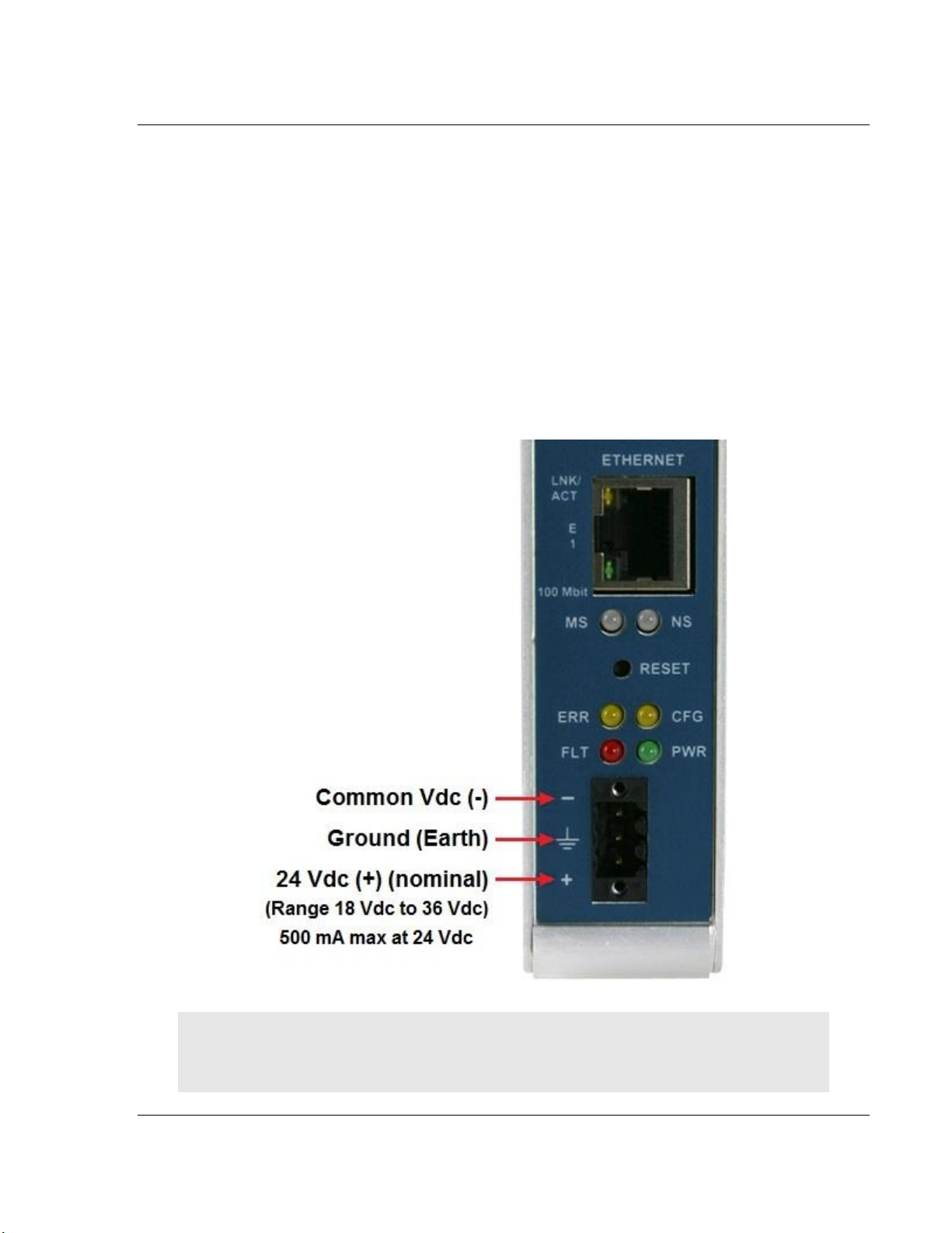
1.6 Connecting Power to the Unit
WARNING: Be sure not to reverse polarity when applying power to the gateway.
This causes permanent damage to the gateway’s internal power distribution
circuits.
ProSoft Technology, Inc. Page 13 of 167
July 2, 2015
Page 14

Start Here PLX8x-EIP-61850 ♦ Communication Gateway
User Manual Server to
IEC 61850 Client
1.7 Installing the ProSoft Software
1.7.1 Installing the ProSoft Discovery Service
ProSoft Discovery Service (PDS) is Windows-based software that connects to
the gateway through the Ethernet port for the following purposes:
Automatic discovery of the gateway on the Ethernet network.
Set a temporary IP address for the gateway for commissioning.
Allow PDS to select the gateway for monitoring and IP address
reconfiguration.
This software is supplied as a stand-alone utility, available on the DVD or
www.prosoft-technolgy.com
1.7.2 Installing the ProSoft EIP-61850 Configuration Manager
You must install the ProSoft 61850 Configuration Manager in order to configure
the gateway. The ProSoft 61850 Configuration Manager is located on the DVD or
www.prosoft-technology.com
Insert the provided DVD into the DVD drive of the PC.
Navigate to your PLX8x-EIP-61850 product.
Choose ProSoft 61850 Configuration Manager to install.
NOTE: To use ProSoft 61850 Configuration Manager under the Windows 7 OS,
you must be sure to install ProSoft 61850 Configuration Manager using the Run
as Administrator option. To find this option, right-click on the Setup.exe installer
program icon, and select Run as Administrator on the context menu. Be aware
that you must install using this option even if you are already logged in as an
Administrator on your network or personal computer (PC). Using the Run as
Administrator option allows the ProSoft 61850 Configuration Manager installer to
create folders and files on your PC with proper permissions and security. If you
do not use the Run as Administrator option, ProSoft 61850 Configuration
Manager may appear to install correctly, but you will receive numerous, repeating
file access errors whenever ProSoft 61850 Configuration Manager is running,
especially when changing configuration screens. If this happens, you must
completely uninstall ProSoft 61850 Configuration Manager and then re-install
using the Run as Administrator option to eliminate the errors.
1.7.3 Installing the ProSoft EIP-61850 Tag Monitor
ProSoft EIP-61850 Tag Monitor is a way to monitor the data tag values through
the gateway. It is automatically installed when you install EIP-61850
Configuration Manager.
Page 14 of 167 ProSoft Technology, Inc.
July 2, 2015
Page 15

PLX8x-EIP-61850 ♦ Communication Gateway Configuring the PLX8x-EIP-61850 Gateway
In This Chapter
Connecting Your PC to the Gateway ..................................................... 15
Setting a Temporary IP Address in the Gateway ................................... 16
Creating a New Project in the Configuration Manager .......................... 17
Exporting a Project from the Configuration Manager ............................. 18
Importing a Project into the Configuration Manager .............................. 19
Configuring the Gateway EtherNet/IP Adapter ...................................... 19
Adding EtherNet/IP Device .................................................................... 21
Importing IEDs Files .............................................................................. 21
Creating the IED Network ...................................................................... 24
Mapping Data Attributes from IEDs to the Gateway .............................. 25
Mapping Tags in the Gateway to EtherNet/IP ....................................... 34
Validating the Configuration .................................................................. 37
Downloading the Configuration File to the Gateway .............................. 38
Uploading the Configuration from the Gateway ..................................... 39
Exporting the IED Add-On Instructions for RSLogix 5000 ..................... 40
Exporting the EIP-61850 Configuration to a File ................................... 40
Importing an Updated IED File .............................................................. 41
Server to
IEC 61850 Client User Manual
2 Configuring the PLX8x-EIP-61850 Gateway
To configure the PLX8x-EIP-61850 gateway, follow these topics in the same
order as they appear in this chapter.
The reason you import the IEDs before you configure the EtherNet/IP device is
that the ProSoft 61850 Configuration Manager takes steps to assist with the
EtherNet/IP configuration after you set up the IEDs in the EIP-61850
Configuration Manager.
2.1 Connecting Your PC to the Gateway
You can use the Ethernet cable included with the gateway to connect your PC to
the gateway’s Ethernet port. If your gateways has two Ethernet ports, refer to
sections 2.2 through 2.6. Later, you can connect the gateway to a switch, through
ProSoft Technology, Inc. Page 15 of 167
July 2, 2015
a patch cable, allowing the IEDs, gateway, and ControlLogix PAC, or
CompactLogix PAC to all operate on the same network.
Once connected, you use the ProSoft Discovery Service to locate the gateway
and assign a temporary IP address (refer to Setting a Temporary IP Address in
the Gateway on page 16). You can set a permanent IP address when you
configure the module (refer to Configuring the Gateway EtherNet/IP Adapter on
page 19).
Page 16
Configuring the PLX8x-EIP-61850 Gateway PLX8x-EIP-61850 ♦ Communication Gateway
User Manual Server to
IEC 61850 Client
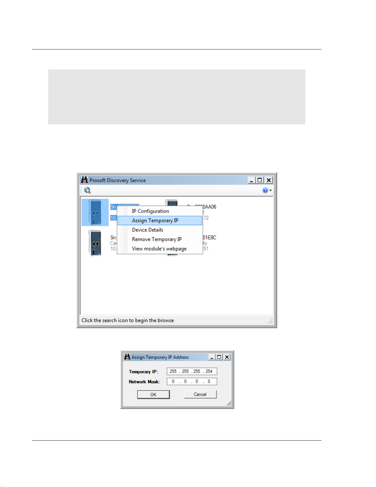
2.2 Setting a Temporary IP Address in the Gateway
Important: ProSoft Discovery Service locates the gateway through UDP broadcast messages.
These messages may be blocked by routers or layer 3 switches. In that case, ProSoft Discovery
Service is unable to locate the gateways.
To use ProSoft Discovery Service, arrange the Ethernet connection so that there is no router/layer
3 switch between the computer and the gateway OR reconfigure the router/layer 3 switch to allow
the routing of the UDP broadcast messages.
1 If you have not installed the ProSoft Discovery Service, refer to Installing the
ProSoft Discovery Service on page 14.
2 Click the Windows START button, and then choose PROGRAMS > PROSOFT
TECHNOLOGY > PROSOFT DISCOVERY SERVICE.
3 Select the module, then right-click and choose ASSIGN TEMPORARY IP.
4 The module’s default IP address is 192.168.0.250.
5 Choose an unused IP within your subnet, and then click OK.
Page 16 of 167 ProSoft Technology, Inc.
July 2, 2015
Page 17
PLX8x-EIP-61850 ♦ Communication Gateway Configuring the PLX8x-EIP-61850 Gateway
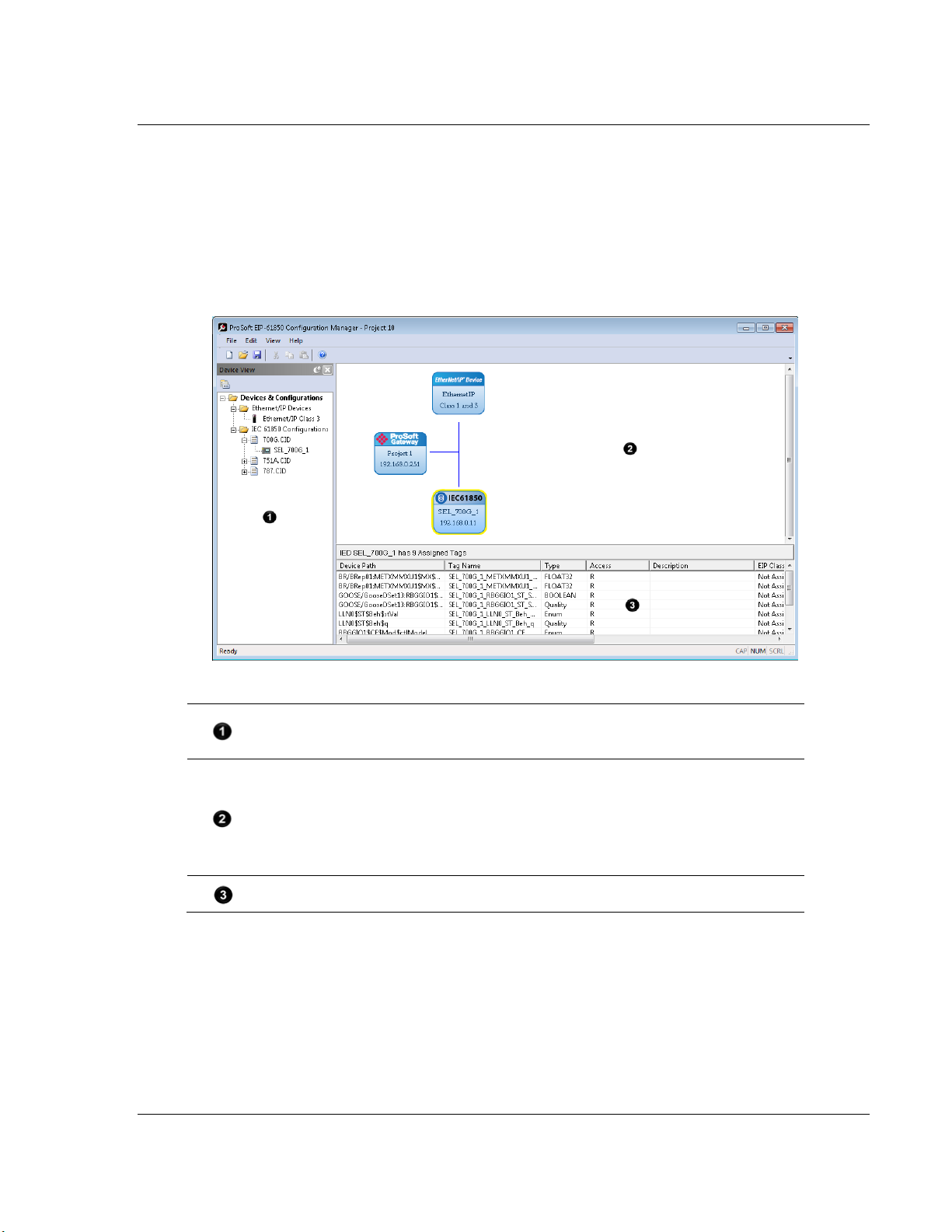
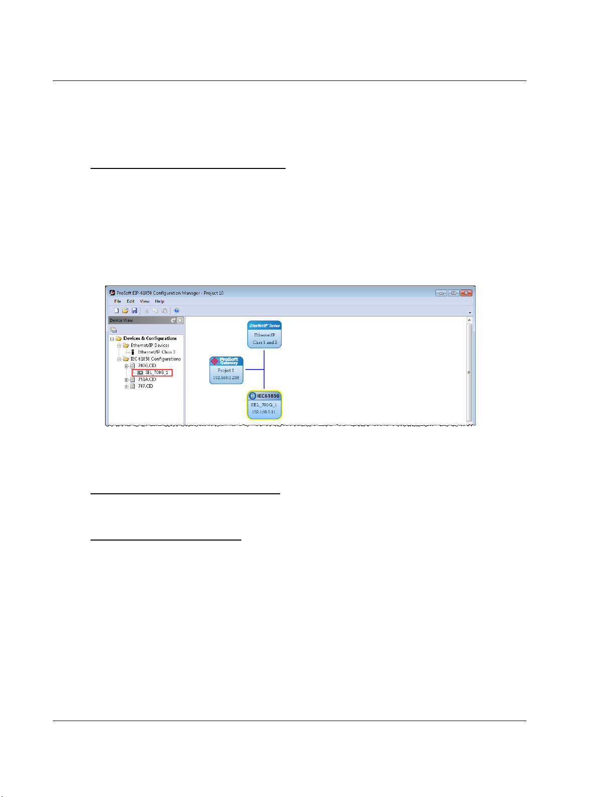
The Device View Tree shows the EtherNet/IP device and IEC 61850 configurations.
The IEC 61850 Configurations folder, is a list of IED configuration files. This folder is
empty until you import IED files.
The Network View pane shows a a graphic representation of the devices to be
connected to the gateway. Each device appears as a “bubble”.
The project bubble (ProSoft Gateway) represents the gateway itself.
The IED bubbles (IEC61850) represent the IEC 61850 port on the gateway, and the
attached devices.
The EtherNet/IP bubbles (EtherNet/IP Device) represent both the EtherNet/IP port
on the gateway, and the attached Ethernet scanners.
The Configured Tags pane shows the configured tags associated with the currently
selected “bubble” in the Network View pane.
Server to
IEC 61850 Client User Manual
2.3 Creating a New Project in the Configuration Manager
You configure the gateway with the ProSoft 61850 Configuration Manager
software. The first step is creating a project for the gateway.
1 If you have not installed the ProSoft EIP-61850 Configuration Manager, refer
to Installing the ProSoft EIP-61850 Configuration Manager on page 14.
2 Click the Windows START button, and then choose PROGRAMS > PROSOFT
TECHNOLOGY > PROSOFT EIP-61850 CONFIGURATION MANAGER.
The ProSoft 61850 Configuration Manager window consists three panes:
When you first start the ProSoft EIP-61850 Configuration Manager, the
Device View shows default devices and configuration, and the Network
View shows only the project bubble (ProSoft Gateway Project 1).
3 Choose FILE > NEW to create a new project.
4 You can rename the project by right-clicking the project bubble and choosing
PROPERTIES. You can also double-click the project bubble.
ProSoft Technology, Inc. Page 17 of 167
July 2, 2015
Page 18
Configuring the PLX8x-EIP-61850 Gateway PLX8x-EIP-61850 ♦ Communication Gateway
User Manual Server to
IEC 61850 Client
5 Enter a new name in PROJECT NAME, and any notes in NOTES, and then click
OK.
6 Save the project by choosing FILE > SAVE AS and entering a name for the
project.
Note: You need a separate Configuration Manager file for each gateway. You can run multiple
instances of the Configuration Manager software at the same time.
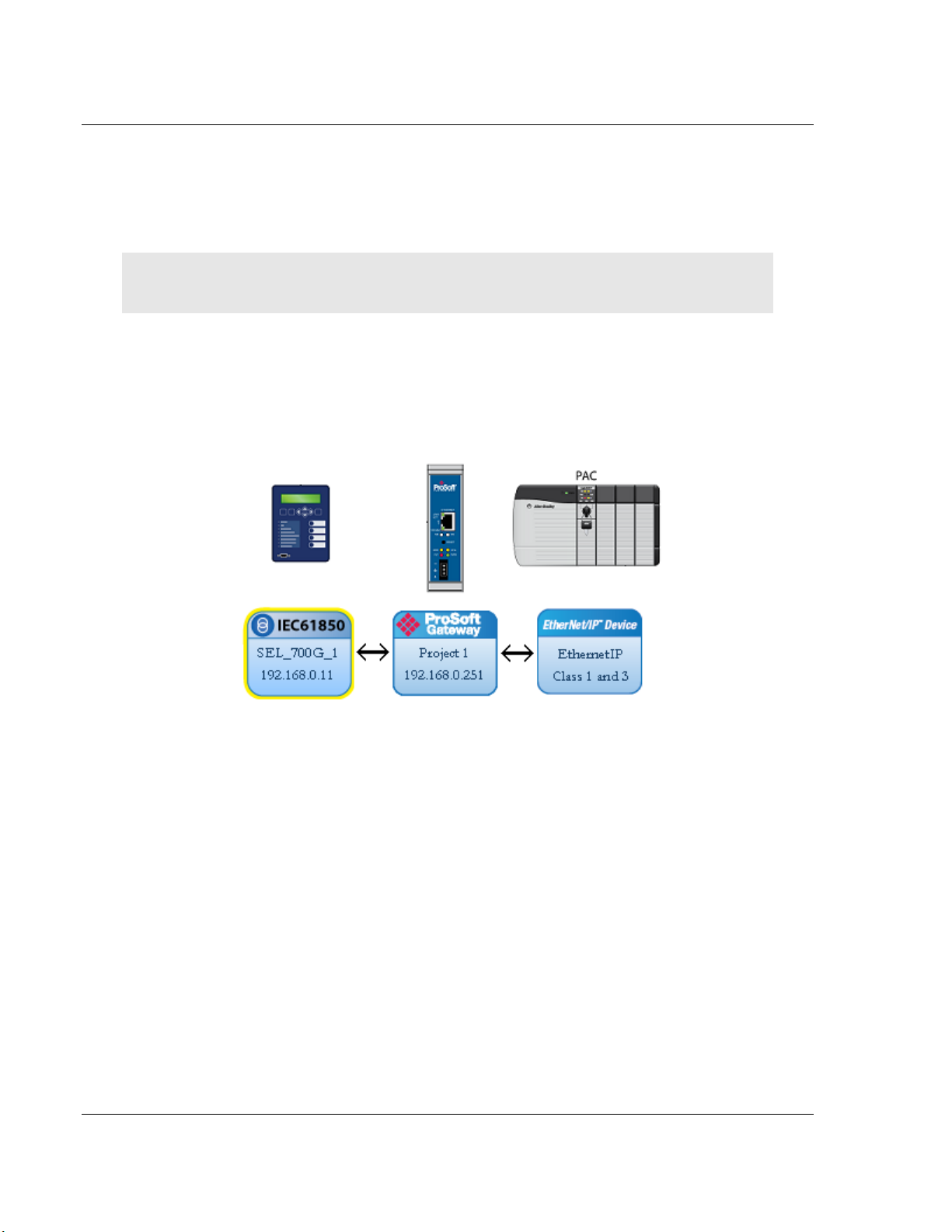
Note that the diagram in the Network View does not exactly match the physical
hardware. In reality, the IED connects to the 61850 “side” of the gateway, while
the EtherNet/IP device connects to the other side. Typically these three devices
are connected across a network, rather than connected directly to each other.
2.4 Exporting a Project from the Configuration Manager
You can export an ProSoft 61850 Configuration Manager file that you created on
your PC. Exporting a project includes all the original IED files that you used to
create the project into the export file. This allows someone on a different PC to
import your configuration file and have all the CID/SCD/ICD files that are part of
your project.
Use FILE > EXPORT CONFIGURATION to export your project.
Page 18 of 167 ProSoft Technology, Inc.
July 2, 2015
Page 19
PLX8x-EIP-61850 ♦ Communication Gateway Configuring the PLX8x-EIP-61850 Gateway
Server to
IEC 61850 Client User Manual
2.5 Importing a Project into the Configuration Manager
You can import an ProSoft 61850 Configuration Manager file that was created
and exported on a different PC. Do not try to open a project file created on
another PC, because it does not contain all the IED files that were used to create
it. Instead, use FILE > IMPORT CONFIGURATION. This recreates all the
CID/SCD/ICD files that were part of the original configuration.
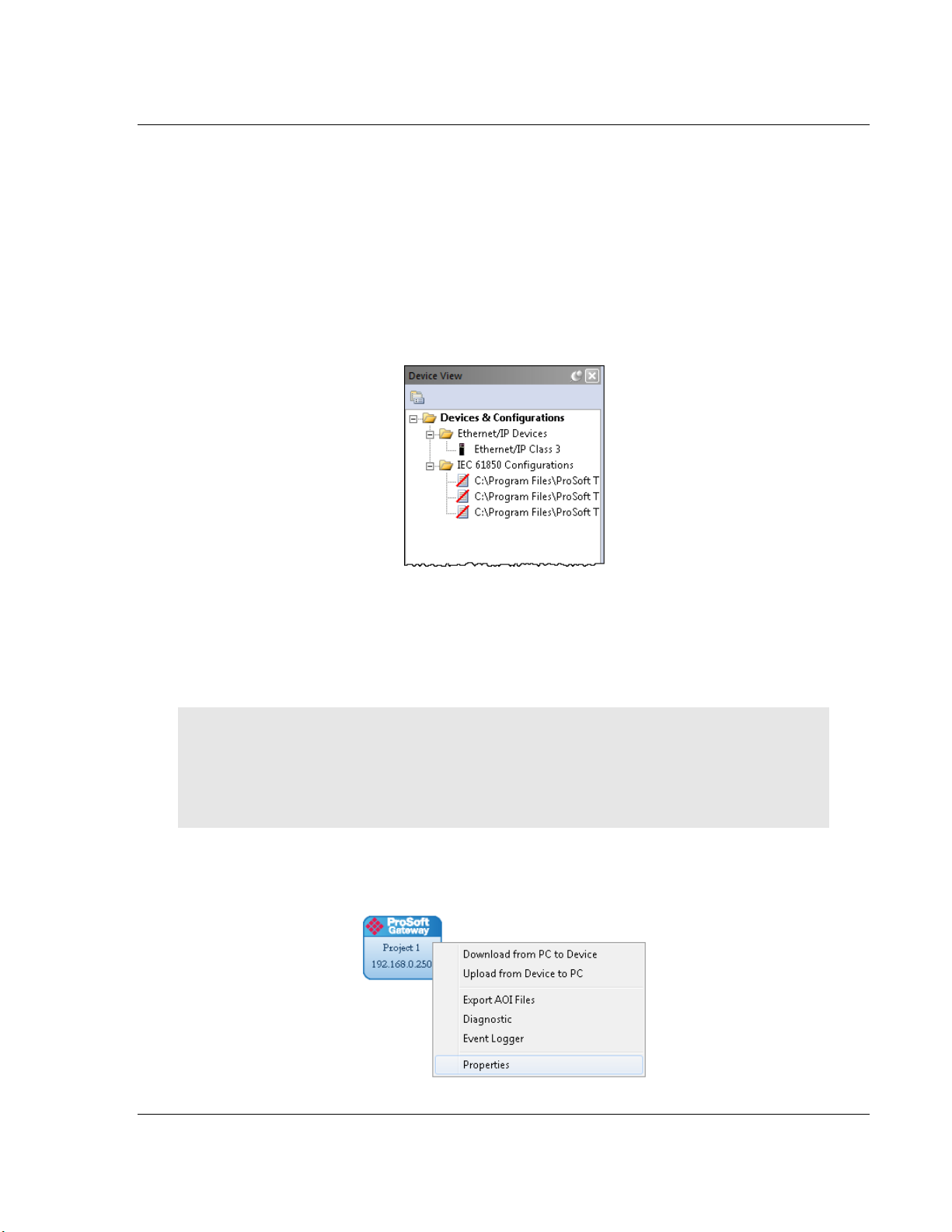
If you open a project not created on your PC instead of importing it, the Device
View shows a red slash through the IED files.
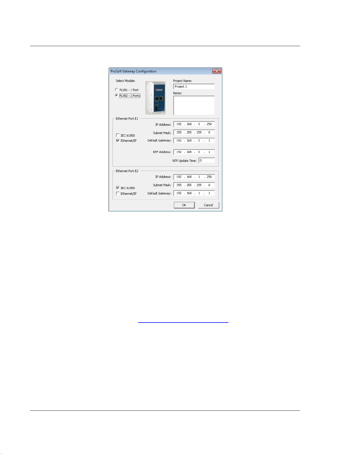
2.6 Configuring the Gateway EtherNet/IP Adapter
Configuring the gateway sets the permanent IP address for the gateway. It also
defines the NTP server that the gateway can poll for the current date and time.
Note: Since the PLX81-EIP-61850 has one physical Ethernet port, both EtherNet/IP and 61850
networks must be on the same subnet.
The PLX82-EIP-61850 has two physical Ethernet ports – one for each protocol. You must
configure these ports on different subnets.
1 Right-click the ProSoft Gateway bubble and choose PROPERTIES. You can
also double-click the ProSoft Gateway bubble.
ProSoft Technology, Inc. Page 19 of 167
July 2, 2015
Page 20
Configuring the PLX8x-EIP-61850 Gateway PLX8x-EIP-61850 ♦ Communication Gateway
User Manual Server to
IEC 61850 Client
This displays the Properties dialog.
2 Choose the correct gateway model (one or two ports).
3 Select the function for the port (IEC 61850 or EtherNet/IP). If the gateway has
two ports, one must be IEC 61850 and the other EtherNet/IP).
4 Enter the IP address and other network information for the gateway port.
o IP Address: The IP address must be a fixed IP address. Contact your
network administrator for assistance.
o Subnet Mask: Enter the gateway’s subnet mask.
o IP Gateway: The IP gateway address is optional, and is not required for
networks that do not use a default gateway.
5 If the gateway has two ports, enter the network information for the second
port.
6 Enter the NTP ADDRESS. The gateway polls the server for the current date
and time. For example, in the USA, there are a number of time servers and
their IP addresses listed at http://tf.nist.gov/tf-cgi/servers.cgi.
7 Enter the NTP UPDATE TIME. This is the polling interval (in minutes) for the
current date and time. A value of 0 means the gateway does not poll the NTP
server.
Page 20 of 167 ProSoft Technology, Inc.
July 2, 2015
Page 21
PLX8x-EIP-61850 ♦ Communication Gateway Configuring the PLX8x-EIP-61850 Gateway
Server to
IEC 61850 Client User Manual
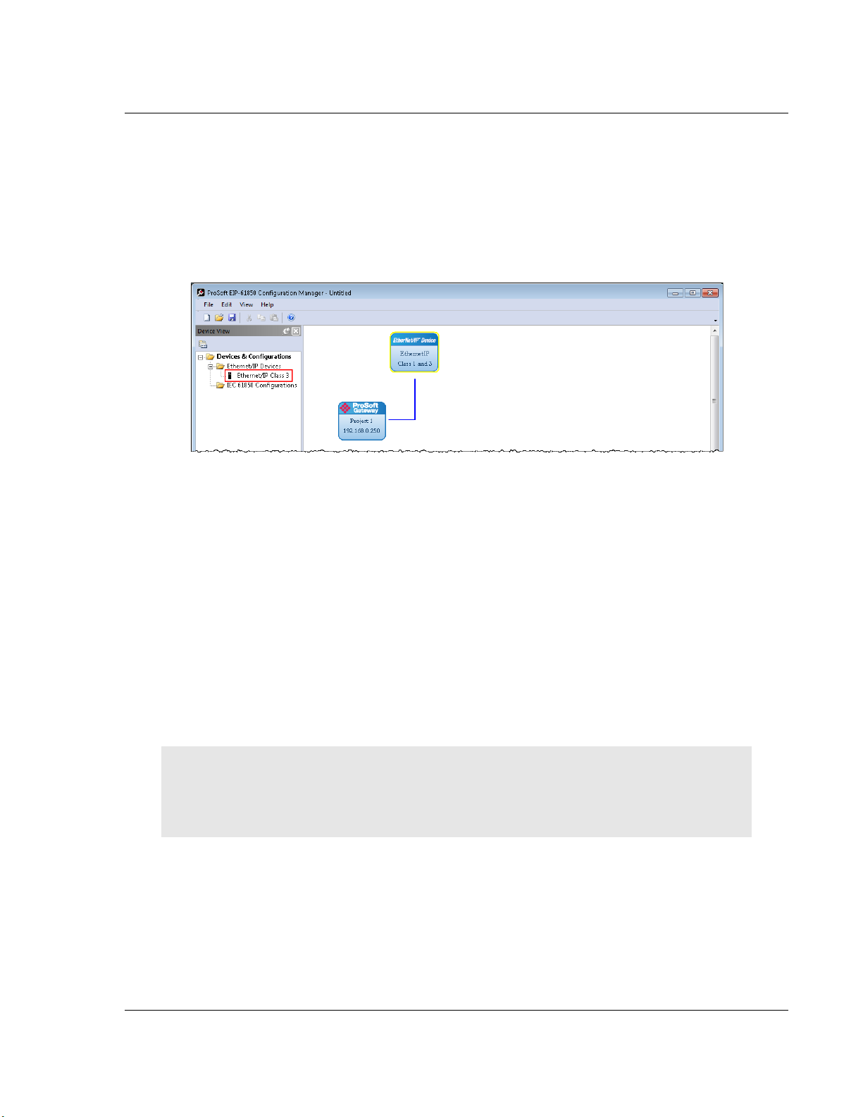
2.7 Adding EtherNet/IP Device
To add an EtherNet/IP device to the network, click and drag an EtherNet/IP
device from the Device View tree into the Network View pane. This creates the
EtherNet/IP Device bubble in the Device View. You use this EtherNet/IP Device
bubble to map the tags that you want to make available to an ethernet scanner
such as PLC or PAC. Refer to Mapping Tags in the Gateway to EtherNet/IP on
page 34.
You can add only one EtherNet/IP device, which you can use to configure both
Class 1 and Class 3 connections.
2.8 Importing IEDs Files
After you have configured the gateway in the project, the next step is to import
the configured IED files into the project. IEDs come with a template ICD file, but
an ICD file indicates possible configuration options. It usually does not contain
specific configuration information. For instance, ICD files usually do not have an
IP Address or other configured elements in them. Once an IED has been
configured (using third-party configuration software provided by the IED
manufacturer), the manufacturer’s software usually creates a specific CID
configuration file. Some third-party software may also create a SCD system
configuration file (an SCD usually has multiple IEDs in it).
Note: You can only import configured ICD , CID, and SCD files. These files must be fully
configured and saved in the software that is used to configure the IEDs. The configured file must
include the IP address, subnet mask, and gateway address (if required by the network). Also, each
IED must have a unique Device Name and IP address.
ProSoft Technology, Inc. Page 21 of 167
July 2, 2015
Page 22
Configuring the PLX8x-EIP-61850 Gateway PLX8x-EIP-61850 ♦ Communication Gateway
User Manual Server to
IEC 61850 Client
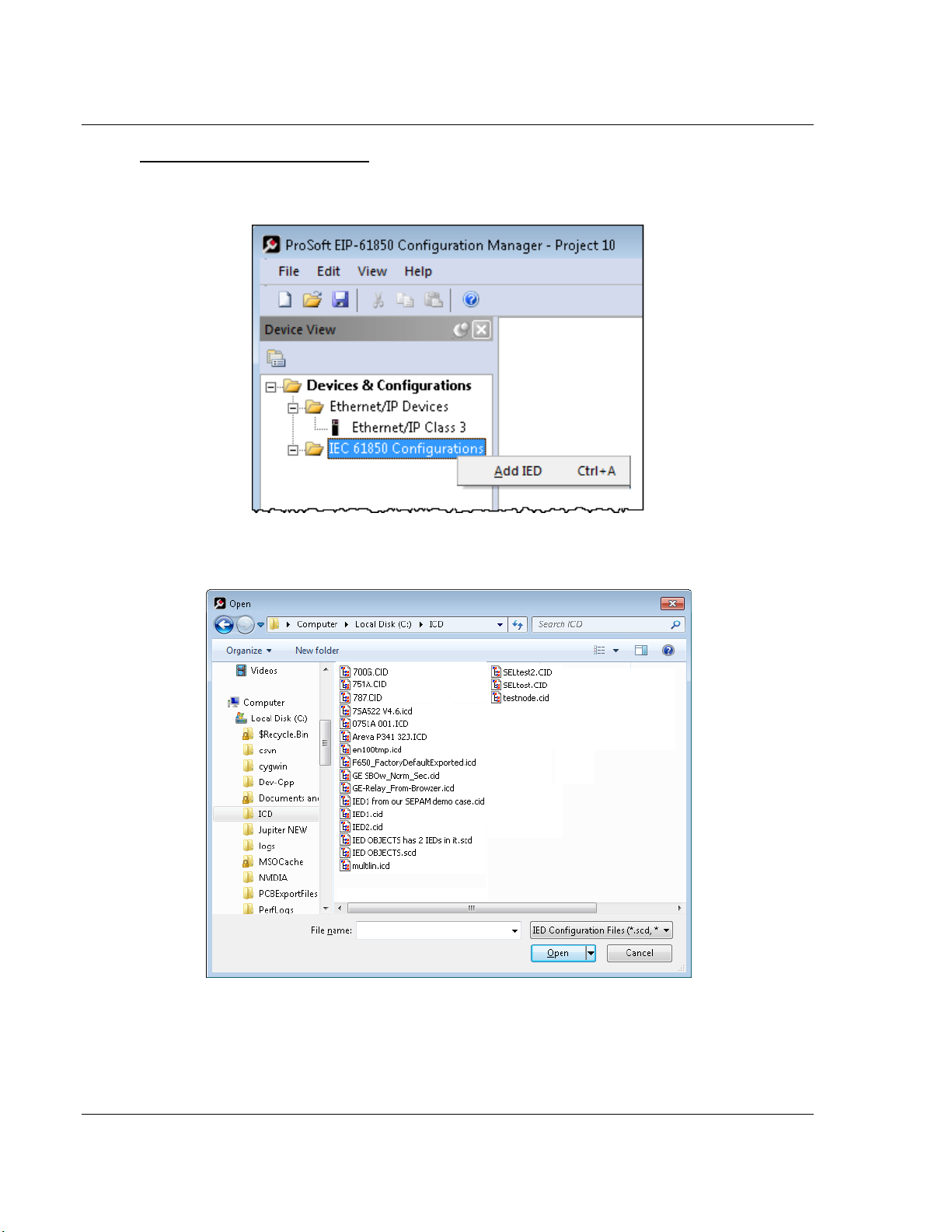
To Import Configured IED Files
1 In the Device View pane of the EIP-61850 Configuration Manager, right-click
IEC 61850 Configuration and choose Add IED.
2 In the Open dialog box, browse to the directory containing the ICD, CID, or
SCD file.
3 Make sure the file type is IED Configuration Files (*.scd, *.icd, *.cid).
Page 22 of 167 ProSoft Technology, Inc.
July 2, 2015
Page 23
PLX8x-EIP-61850 ♦ Communication Gateway Configuring the PLX8x-EIP-61850 Gateway
Server to
IEC 61850 Client User Manual
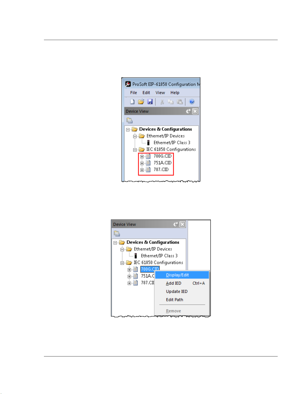
4 Each IED has its own configuration file, except for SCD files which can
contain more than one IED. Select one or more configuration files to import
and click OPEN. The imported IED files appear in the Device View tree under
IEC 61850 Configuration.
5 Repeat the above steps to import the rest of your IED files.
6 If you are familiar with the contents of CID, SCD, and ICD files, you can right-
click the file name and choose DISPLAY/EDIT to see the contents of the file in
the default text editor.
ProSoft Technology, Inc. Page 23 of 167
July 2, 2015
Page 24
Configuring the PLX8x-EIP-61850 Gateway PLX8x-EIP-61850 ♦ Communication Gateway
User Manual Server to
IEC 61850 Client
2.9 Creating the IED Network
After you have imported the IED files , you can create the IED 61950 network in
the EIP-61850 Configuration Manager.
To Create the IED Network Configuration
1 In the Device View pane of the Configuration Manager, expand the IED file
name (700G.CID in this example) by clicking the “+” sign next to the file
name.
2 Click and drag the IED name (SEL_700G_1 in this example) from the Device
View pane into the Network View. When you release the mouse button, the
IED is added to the view in an IEC 61850 bubble. The bubble shows the IED
Device Name and IP address. These values are from the IED file and cannot
be changed in the Configuration Manager.
3 Repeat the above steps to add the rest of your IEDs to the Network View
pane.
To delete an IED from the Network View
Right-click the IED bubble in the Network View and choose DELETE.
To change the MMS Scan Delay
You can change the MMS Scan Delay for any IED. This is the only property you
can change for an IED, as everything else is set in the IED configuration file.
IEC 61850 Reports and GOOSE messages are generated by the IED and are
not affected by the MMS Scan Delay. The MMS Scan Delay parameter also has
no impact on MMS writes. The lower you set the MMS Scan Delay value, the
more network capacity is consumed by MMS Read network traffic. If you do not
configure an IED to read any Data Attributes using MMS messages, then this
parameter has no effect.
Right-click the IED bubble in the Network View and choose PROPERTIES. By
default, the MMS SCAN DELAY is set to 1000 milliseconds.
Page 24 of 167 ProSoft Technology, Inc.
July 2, 2015
Page 25
PLX8x-EIP-61850 ♦ Communication Gateway Configuring the PLX8x-EIP-61850 Gateway
Server to
IEC 61850 Client User Manual
To locate the IED file
The Configuration Manager stores its own copy of the CID, SCD, or ICD file for
this IED.
1 Right-click the IED bubble in the Network View and choose PROPERTIES.
2 Click the Detailed Properties tab to see the path on your PC where the
Configuration Manager stores the file.
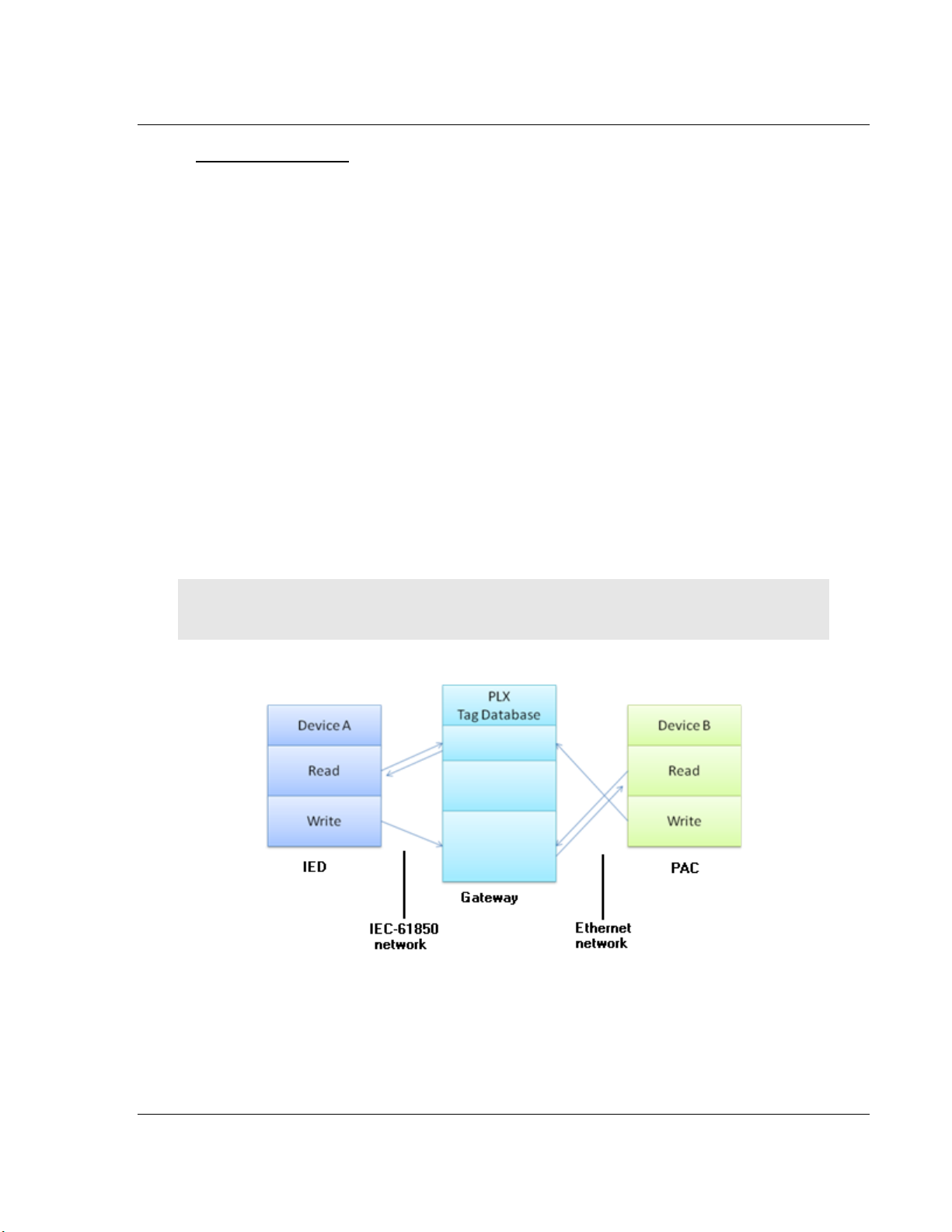
2.10 Mapping Data Attributes from IEDs to the Gateway
As you add IEDs to the Network View, the ProSoft 61850 Configuration Manager
reads the device information and builds a list of tags (Data Attributes) from the
device file. In this step, you map tags from the IED to the gateway database. This
is the first of two steps in mapping data from the IED to the PAC:
1 First, you map the tag from the device to the gateway. This creates a location
in the gateway database to store the data associated with the tags.
2 Second, you map the tag from the gateway database to the gateway
Etherenet/IP port. This sets up an MMS data movement (IEC 61850-8-1) to
push the data to the Logix processor (if the tag can be read) or to write to
data to the D(if the tag can be written). Refer to Mapping Tags in the
Gateway to EtherNet/IP on page 34 for this second step.
Note: Remember that you must configure the gateway so that the IP address is in the same subnet
as the 61850 relay device. Refer to Configuring the Gateway EtherNet/IP Adapter on page 19.
ProSoft Technology, Inc. Page 25 of 167
July 2, 2015
Page 26
Configuring the PLX8x-EIP-61850 Gateway PLX8x-EIP-61850 ♦ Communication Gateway
User Manual Server to
IEC 61850 Client
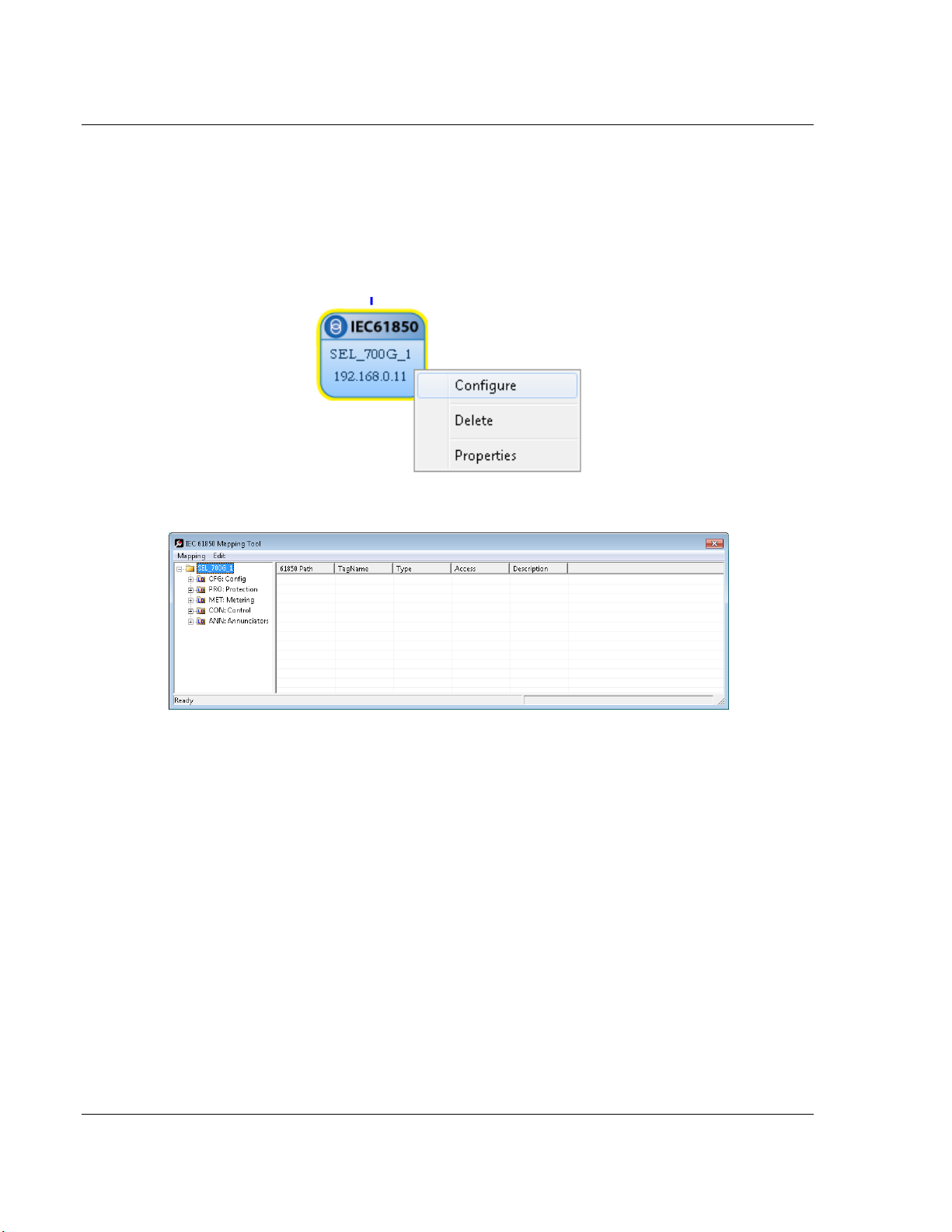
2.10.1 Mapping MMS Messages
MMS messages can be read-only (read the value from the IED) or write (write
the value to the IED).
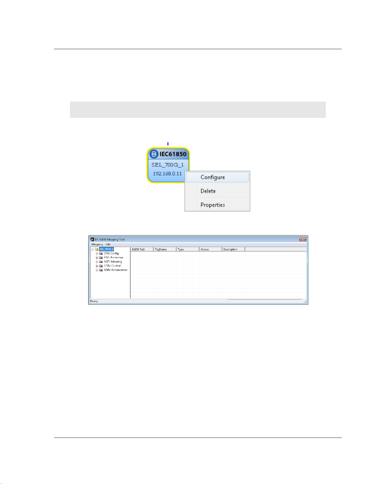
1 In the Network View pane in the EIP-61850 Configuration Manager, right-click
the IED bubble that you want to map, and choose CONFIGURE.
This displays the IEC 61850 Mapping Tool window.
2 In the treeview on the left, expand (click the + sign) the root folder. This
shows the Logical Devices (notice the little LD in the icon) in the IED.
3 Expand (click the + sign) on one of the Logical Devices in the IED to see the
Logical Nodes (notice the little LN in the icon) within it. Some IED
manufacturers provide descriptive information in their CID files. ProSoft
ProSoft 61850 Configuration Manager displays that information after the
Logical Node name.
4 Continue to expand the Logical Node to display the Data Object (DO) and
finally the individual Data Attributes.
Page 26 of 167 ProSoft Technology, Inc.
July 2, 2015
Page 27

PLX8x-EIP-61850 ♦ Communication Gateway Configuring the PLX8x-EIP-61850 Gateway
Server to
IEC 61850 Client User Manual
5 Click and drag a Data Attribute from the tree into the mapping table on the
right. When you drop the Data Attribute, it fills in the table with the following
values:
o 61850 PATH to the Data Attribute.
o TAGNAME generated for the Data Attribute. This can be quite long, and is
close to the actual Data Attribute name. Most devices have tag names
that are short enough to map to RSLogix5000 projects. For tags that
exceed this length, the Configuration Manager automatically shortens the
name, ending with a sequence number ( _001, _002, …).
o TYPE is the data type for the Data Attribute.
o ACCESS: ProSoft ProSoft 61850 Configuration Manager determines the
read/write access of the tab the tag’s functional constraints.
R indicates data that the gateway can read from the the IED.
W indicates data that the gateway can write to the IED.
6 To rename a tag, click in the TAGNAME column and type in a new name.
7 To delete tags, select the tag or tags in the table, then right-click the selected
tags and choose DELETE.
8 Repeat until you have mapped the tags for the IED.
ProSoft Technology, Inc. Page 27 of 167
July 2, 2015
Page 28
Configuring the PLX8x-EIP-61850 Gateway PLX8x-EIP-61850 ♦ Communication Gateway
User Manual Server to
IEC 61850 Client
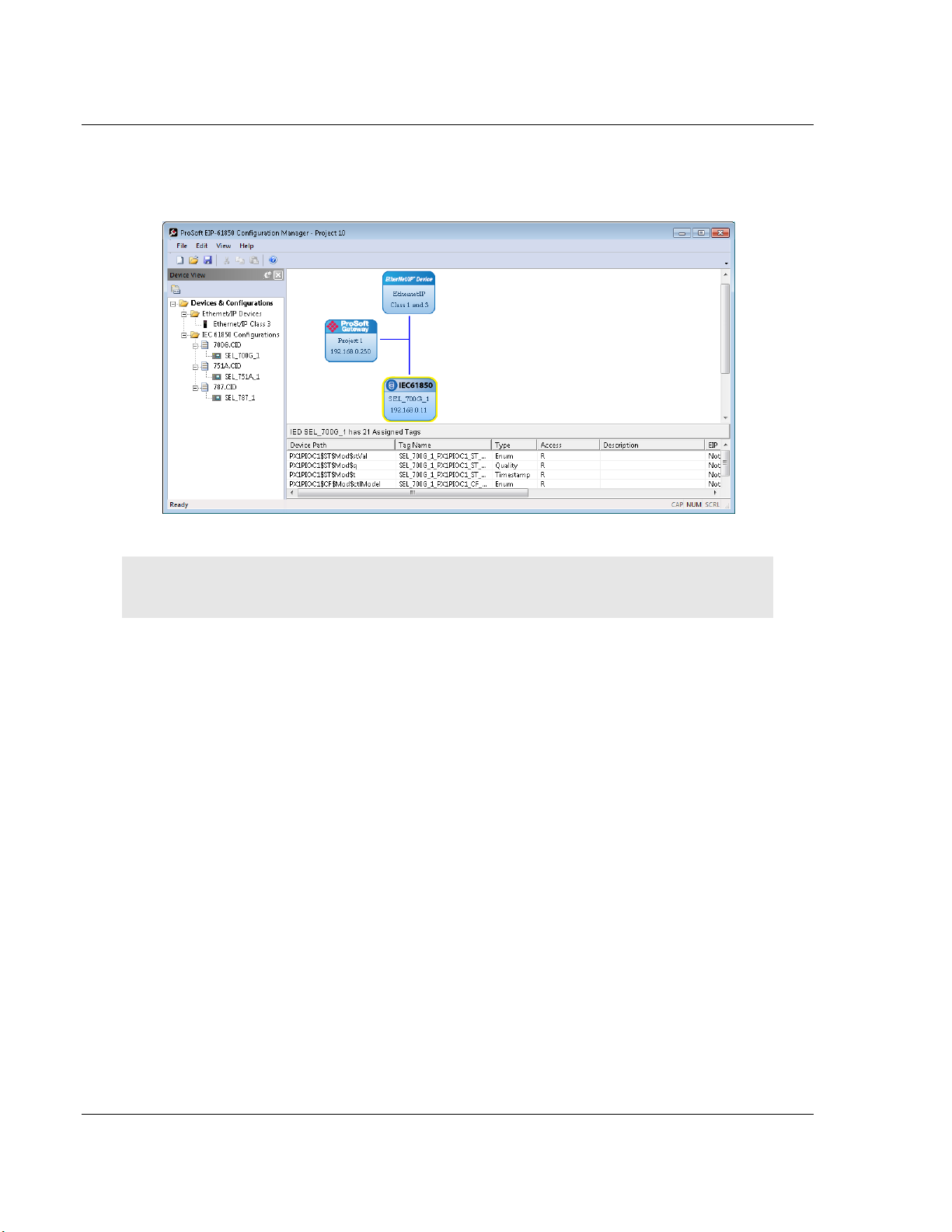
9 Choose MAPPING > SAVE to save the tag mapping. The mapped tags appear
in the Assigned Tags pane at the lower-right of the Configuration Manager
when you click the IED bubble.
Note: You can click and drag a higher level object (such as a logical node (LN), a logical device
(LD), or the IED to map ALL the child tags descending from the higher level object.
10 At this point, you have mapped the tags from the IED to the gateway internal
database. If you download the configuration to the gateway at this point, the
IEC 61850 Client starts to read the values of the Data Attributes from the IED.
The next step is to map the tags from the internal database to the EtherNet/IP
output (refer to Mapping Tags in the Gateway to EtherNet/IP on page 34).
11 If you want to delete one or more mappings, refer to Deleting one or more
IEC 61850 mappings on page 33.
You can map other data from the IED. Refer to:
Mapping Reports on page 29
Mapping GOOSE Messages on page 31
Page 28 of 167 ProSoft Technology, Inc.
July 2, 2015
Page 29
PLX8x-EIP-61850 ♦ Communication Gateway Configuring the PLX8x-EIP-61850 Gateway
Server to
IEC 61850 Client User Manual
2.10.2 Mapping Reports
Reports are based upon a DATA-SET, containing a specific collection of Data
Attributes. You can configure the gateway to enable an IED’s Buffered Report
Control Blocks (BRCBs) or Unbuffered Report Control Blocks (URCBs).
Note: Be sure that the DATA-SET on your IED contains all Data Attributes and not Data Objects.
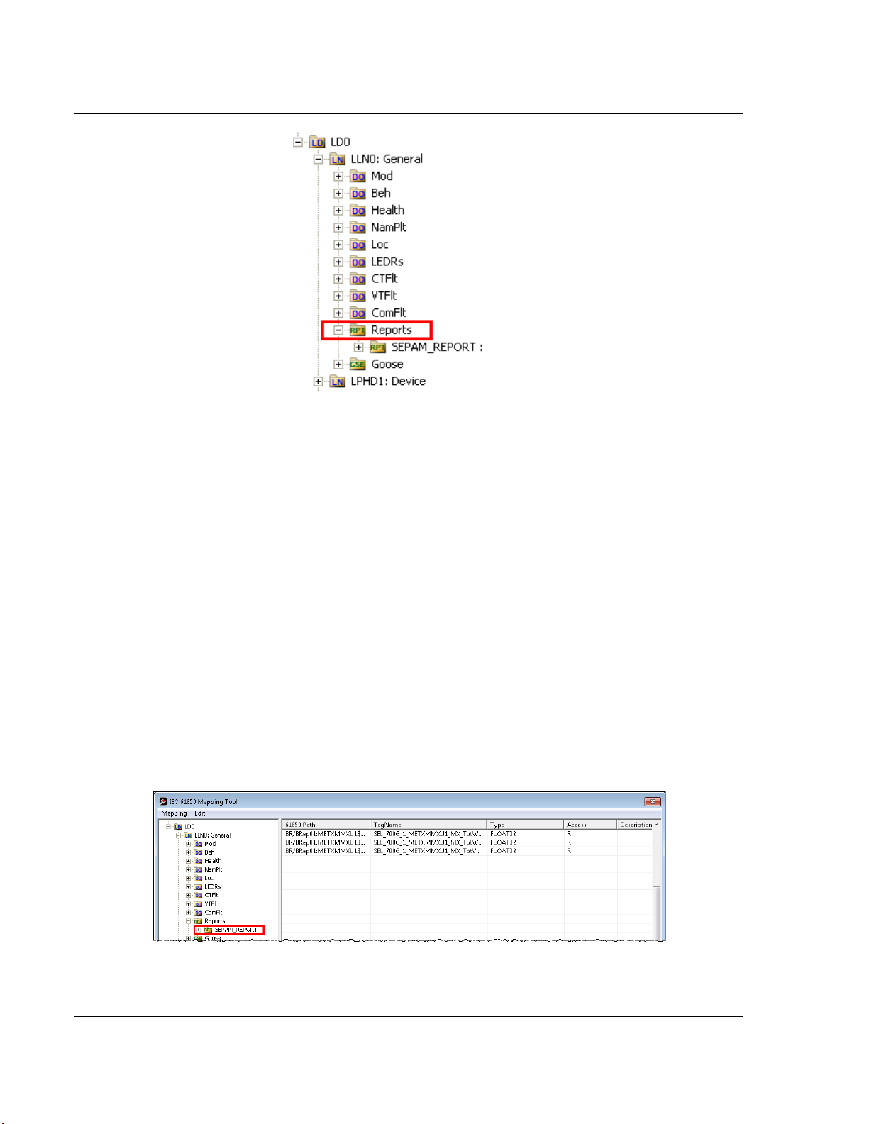
1 In the Network View pane in the EIP-61850 Configuration Manager, right-click
the IED bubble that you want to map, and choose CONFIGURE.
This displays the IEC 61850 Mapping Tool window.
2 In the treeview on the left, expand (click the + sign) the root folder.
3 Expand (click the + sign) the Logical Device to see the Logical Nodes.
4 Continue to expand the Logical Node to display the Reports Object (RPT)
and finally the individual Reports.
ProSoft Technology, Inc. Page 29 of 167
July 2, 2015
Page 30
Configuring the PLX8x-EIP-61850 Gateway PLX8x-EIP-61850 ♦ Communication Gateway
User Manual Server to
IEC 61850 Client
You can write-click on a report name and choose PROPERTIES to see more
information about the report.
5 Click and drag the yellow folder showing the report name from the left side to
the right side of the window. This maps the entire DATA-SET. You can also
expand the individual report, then click and drag individual Data Attributes to
the right side of the window.
6 The Configuration Manager automatically populates the table with one row for
each Data Attribute in that DATA-SET. When you drop the report or Data
Attribute, it fills in the table with the following values:
o 61850 PATH to the Data Attribute.
o TAGNAME generated for the Data Attribute. This can be quite long, and is
close to the actual Data Attribute name. Most devices have tag names
that are short enough to map to RSLogix5000 projects. For tags that
exceed this length, the Configuration Manager automatically shortens the
name, ending with a sequence number ( _001, _002, …).
o TYPE is the data type for the Data Attribute.
o ACCESS: ProSoft ProSoft 61850 Configuration Manager determines the
read/write access of the tab the tag’s functional constraints.
R indicates data that the gateway can read from the the IED.
W indicates data that the gateway can write to the IED.
7 To delete tags, select the tag or tags in the table, then right-click the selected
tags and choose DELETE.
Page 30 of 167 ProSoft Technology, Inc.
July 2, 2015
Page 31

PLX8x-EIP-61850 ♦ Communication Gateway Configuring the PLX8x-EIP-61850 Gateway
Server to
IEC 61850 Client User Manual
8 Repeat until you have mapped the reports and individual Data Attributes for
the IED.
9 Choose MAPPING > SAVE to save the tag mapping. The mapped report tags
appear in the Assigned Tags pane at the lower-right of the Configuration
Manager when you click the IED bubble.
2.10.3 Mapping GOOSE Messages
GOOSE (Generic Object Oriented Substation Events) messages are based upon
a DATA-SET, containing a specific collection of Data Attributes. You can
configure the gateway to enable an IED’s GOOSE messages.
1 In the Network View pane in the EIP-61850 Configuration Manager, right-click
the IED bubble that you want to map, and choose CONFIGURE.
ProSoft Technology, Inc. Page 31 of 167
July 2, 2015
Page 32

Configuring the PLX8x-EIP-61850 Gateway PLX8x-EIP-61850 ♦ Communication Gateway
User Manual Server to
IEC 61850 Client
This displays the IEC 61850 Mapping Tool window.
2 In the treeview on the left, expand (click the + sign) the root folder.
3 Expand (click the + sign) the Logical Device to see the Logical Nodes.
4 Continue to expand the Logical Node to display the GOOSE (GSE) and
finally the individual DATA-SETS.
5 Click and drag the yellow folder showing the DATA-SET name from the left
side to the right side of the window. This maps the entire DATA-SET. You
can also expand the individual DATA-SET, then click and drag individual
Data Attributes to the right side of the window.
6 The Configuration Manager automatically populates the table with one row for
each Data Attribute in that DATA-SET. When you drop the report or Data
Attribute, it fills in the table with the following values:
o 61850 PATH to the Data Attribute.
o TAGNAME generated for the Data Attribute. This can be quite long, and is
close to the actual Data Attribute name. Most devices have tag names
that are short enough to map to RSLogix5000 projects. For tags that
exceed this length, the Configuration Manager automatically shortens the
name, ending with a sequence number ( _001, _002, …).
o TYPE is the data type for the Data Attribute.
o ACCESS: ProSoft ProSoft 61850 Configuration Manager determines the
read/write access of the tab the tag’s functional constraints.
R indicates data that the gateway can read from the the IED.
W indicates data that the gateway can write to the IED.
Page 32 of 167 ProSoft Technology, Inc.
July 2, 2015
Page 33

PLX8x-EIP-61850 ♦ Communication Gateway Configuring the PLX8x-EIP-61850 Gateway
Server to
IEC 61850 Client User Manual
7 To delete tags, select the tag or tags in the table, then right-click the selected
tags and choose DELETE.
8 Repeat until you have mapped the GOOSE DATA-SETS and individual Data
Attributes for the IED.
9 Choose MAPPING > SAVE to save the tag mapping. The mapped tags appear
in the Assigned Tags pane at the lower-right of the Configuration Manager
when you click the IED bubble.
2.10.4 Deleting one or more IEC 61850 mappings
You can delete one or more MMS messages, Report, and GOOSE mapping from
the IED to the gateway.
1 In the Network View pane in the EIP-61850 Configuration Manager, right-click
the IED bubble that you want to map, and choose CONFIGURE.
This displays the IEC 61850 Mapping Tool window. The mappings are listed
in the table on the right side of the window.
2 Select the mappings in the table, then right-click the selected mappings and
choose DELETE. You can also delete all the mappings by choosing EDIT >
CLEAR ALL.
3 Note that if you delete a mapping from the IED to the Gateway, you also
delete the corresponding mapping on the EtherNet/IP side of the Gateway
(see Mapping Tags in the Gateway to EtherNet/IP on page 34).
ProSoft Technology, Inc. Page 33 of 167
July 2, 2015
Page 34

Configuring the PLX8x-EIP-61850 Gateway PLX8x-EIP-61850 ♦ Communication Gateway
User Manual Server to
IEC 61850 Client
2.11 Mapping Tags in the Gateway to EtherNet/IP
After you have mapped the MMS messages, Report, and GOOSE mapping from
the IED to the gateway, you must map these tags to the EtherNet/IP side of the
gateway. This makes the tags and associated data available to the PLC. This is
the second of two steps in mapping data from the IED to the PAC.
1 First, you mapped the tag from the device to the gateway. This creates a
location in the gateway database to store the data associated with the tags.
Refer to Mapping Data Attributes from IEDs to the Gateway on page 25 for
this first step.
2 Second, you map the tag from the gateway database to the gateway
Etherenet/IP port. This sets up an MMS data movement (IEC 61850-8-1) to
push the data to the Logix processor (if the tag can be read) or to write to
data to the IED (if the tag can be written).
In the Network View pane in the EIP-61850 Configuration Manager, double-click
the EtherNet/IP Device bubble.
Page 34 of 167 ProSoft Technology, Inc.
July 2, 2015
Page 35

PLX8x-EIP-61850 ♦ Communication Gateway Configuring the PLX8x-EIP-61850 Gateway
Server to
IEC 61850 Client User Manual
This displays the EtherNet/IP Mapping Tool window.
The mapped tags (Data Attributes) appear on the left-hand side of the window.
The tags are highlighted in one of three colors:
Tags that can be read from the IED are highlighted in yellow.
Tags that can be written to the IED are highlighted in blue.
Tags that are string data are highlighted in Brown. This includes tags from
Reports.
Tags that come from GOOSE messages are highlighted in purple.
You must map tags to an output on the right-hand side. You must map the
available tags on the left-hand side to one of the three tabs on the right-hand side
of the window.
Class 1 INPUTS is for tags that can be read from the IED (yellow, brown,
purple to Firefox). These are output on the gateway EtherNet/IP as Class 1
messages. For more on Class 1 inputs, see Specifications - EtherNet/IP on
page 80.
Class 2 OUTPUTS is for tags that can be written to the IED (blue). Write tags
are highlighted in blue. These can be written by the PLC to EtherNet/IP on
the gateway as Class 1 messages.
Class 3 MSGs is for any tag. In particular, if your application requires more
Data Attributes than the supported number of bytes that can be transferred by
EtherNet/IP Class 1 messaging, you must use Class 3 messages. These
must be explicitly read or written by the PLC using Class 3 messaging. For
more on Class 3 messages, see Specifications - EtherNet/IP on page 80.
ProSoft Technology, Inc. Page 35 of 167
July 2, 2015
Page 36

Configuring the PLX8x-EIP-61850 Gateway PLX8x-EIP-61850 ♦ Communication Gateway
User Manual Server to
IEC 61850 Client
The Conn slider allows you to choose the connection for the tags you are about
to map as Class 1 Inputs or Class 2 OUTPUTs. For the PLX81-EIP61850, you
can map tags to as many as 10 connections to 10 different PLCs, and each tag
can be mapped to only one connection. For the PLX82-EIP61850, you can map
tags to as many as 20 connections to 20 different PLCs, and each tag can be
mapped to only one connection. Class 3 messages are explicit messages where
you edit and create MSG instructions in the PLC to read/write to specific areas of
the gateway memory. No connection parameters need to be defined.
You can map tags in several ways:
You can click and drag one or more tags from the left-hand side to the current
tab right-hand side.
You can select one or more tags and click ASSIGN.
You can map all the tags by clicking AUTO ASSIGN. This automatically maps
all the available tags to the correct tab. All read tags are mapped to Class 1,
and all write tags are mapped to Class 2.
If you try to map a tag to the wrong tab using click and drag, or the ASSIGN
button, the Configuration Manager displays an error message and maps the
tag to the correct tab.
To delete one or more mappings
Select the mappings you want to delete in the right-hand table, then click UNDO.
You can delete all mappings by clicking RESET ALL. Deleting a mapping on the
EtherNet/IP side of the gateway does not delet the mapping from the IED to the
Gateway.
Note that if you delete a mapping from the IED to the Gateway, you also delete
the corresponding mapping on the EtherNet/IP side of the Gateway (see Deleting
one or more IEC 61850 mappings on page 33).
Page 36 of 167 ProSoft Technology, Inc.
July 2, 2015
Page 37

PLX8x-EIP-61850 ♦ Communication Gateway Configuring the PLX8x-EIP-61850 Gateway
Server to
IEC 61850 Client User Manual
2.12 Validating the Configuration
You can validate the configuration file before downloading it to the gateway.
1 Right-click the Project bubble and choose DOWNLOAD FROM PC TO DEVICE.
This displays the Transfer File dialog box.
2 Click VALIDATE CONFIGURATION to confirm that the IED’s and the IEC 61850
configuration of the gateway have a correct network IP range that allows the
module to communicate with the IED devices. If the IED is not on the same
network as the IEC 61850, then the software displays an error message:
The gateway and IED <name> are not on the same network.
ProSoft Technology, Inc. Page 37 of 167
July 2, 2015
Page 38

Configuring the PLX8x-EIP-61850 Gateway PLX8x-EIP-61850 ♦ Communication Gateway
User Manual Server to
IEC 61850 Client
2.13 Downloading the Configuration File to the Gateway
After you have created the IEC 61850 project in the Configuration Manager
software, you are ready to download it to the gateway.
Note: If you want to validate the configuration before downloading, refer to
Validating the Configuration on page 37.
1 Right-click the Project bubble and choose DOWNLOAD FROM PC TO DEVICE.
This displays the Transfer File dialog box.
2 Click TEST CONNECTION. If the gateway’s IP address does not match what
was entered in EIP-61850 Configuration Manager, then the software displays
an error message:
Error: Connecting to Module. Please check your IP Address.
If the gateway's IP address matches the address in the Configuration
Manager, and the software displays the following message:
Successfully Connected.
3 Click DOWNLOAD to download the project to the gateway.
NOTE: If you see the Error: Download Configuration message, make sure that the MODE 3
jumper is correctly installed on the module, since a configuration download is only allowed when
the jumper is installed. Refer to Setting Jumpers on page 11.
If you need to change MODE 3 jumper, note that the jumper setting is only read by the module
when it powers up; therefore you must reboot the gateway before it can recognize the change in
the jumper setting.
Page 38 of 167 ProSoft Technology, Inc.
July 2, 2015
Page 39

PLX8x-EIP-61850 ♦ Communication Gateway Configuring the PLX8x-EIP-61850 Gateway
Server to
IEC 61850 Client User Manual
2.14 Uploading the Configuration from the Gateway
You can use this feature to retrieve the configuration from the gateway. Not only
does it retrieve the configuration, but is also retrieves all the CID, ICD, and/or
SCD files used in creating that configuration. There are several reasons that you
might use this feature:
You want to modify the configuration, but do not have access to the original
configuration files.
You want to copy a configuration from one gateway to another gateway.
You want to back up the configuration for safety.
Warning: This function replaces the current configuration in the ProSoft ProSoft 61850
Configuration Manager with the one from the gateway. Make sure you save the current
configuration before uploading the configuration from the gateway.
1 Optional: Create a new project in the ProSoft 61850 Configuration Manager
by choosing FILE > NEW.
2 Right-click the ProSoft Gateway bubble and choose UPLOAD FROM DEVICE TO
PC.
The Configuration Manager uploads the configuration from the gateway and
displays it. You can then edit the configuration or save it on the computer.
ProSoft Technology, Inc. Page 39 of 167
July 2, 2015
Page 40

Configuring the PLX8x-EIP-61850 Gateway PLX8x-EIP-61850 ♦ Communication Gateway
User Manual Server to
IEC 61850 Client
2.15 Exporting the IED Add-On Instructions for RSLogix 5000
After downloading a configuration file to the module, you must export the Add-On
Instruction (.L5X) file to be used in RSLogix 5000. This creates the Add-On
Instructions for the IEDs that you imported (refer to Importing IEDs Files on page
21). The ProSoft 61850 Configuration Manager creates one AOI file for each IED
in the network configuration (IEDs that appear as bubbles in the Network View
pane).
1 To export the IED files, right-click the ProSoft Gateway bubble in the Network
View and choose EXPORT AOI FILES.
2 In the Save As dialog box, navigate to the correct directory and save the AOI
files.
Note: Each IED in the network configuration must have a unique device name because the
Configuration Manager uses the name to build the Add-On Instruction. The .L5X AOI file contains
all the tags and ladder logic defined in your IEC 61850 project. Since the Configuration Manager
builds a User-Defined Data Type (UDT) for RSLogix 5000, each device must have fewer than 512
configured IEC 61850 tags (with a BOOL data type occupying 2 tags, and all other data types
occupying one tag).
2.16 Exporting the EIP-61850 Configuration to a File
If you want to back up a configuration, or move it to another PC, you must export
the configuration to a file. If you need assistance from ProSoft Technology
Technical Support, they will need your configuration file.
1 To export the configuration, choose FILE / EXPORT CONFIGURATION.
2 In the Save As dialog box, navigate to the correct directory and save the
configuration file.
To export only the IED files that you have added to the network configuration,
refer to Exporting a Project from the Configuration Manager page 18.
Note: You can also upload the configuration from the gateway, and then save it to a file. Refer to
Uploading the Configuration from the Gateway on page 39.
Page 40 of 167 ProSoft Technology, Inc.
July 2, 2015
Page 41

PLX8x-EIP-61850 ♦ Communication Gateway Configuring the PLX8x-EIP-61850 Gateway
Server to
IEC 61850 Client User Manual
2.17 Importing an Updated IED File
You may need to make changes to the CID, ICD, or SCD files after you create
the IED system configuration in the gateway. For example, you may need to
modify a DATA-SET, or add or remove some Data Attributes. When you make
changes like this, it’s easy to update the project in the ProSoft ProSoft 61850
Configuration Manager with the new information.
1 Right-mouse-click on the CID, SCD, OR ICD filename you want to update in
the Device View section of ProSoft 61850 Configuration Manager and choose
UPDATE IED.
2 In the Open dialog box, browse to the directory containing the ICD, CID, or
SCD file. Often you use the exact same filename as when you first imported
the file into ProSoft EIP-61850 Configuration Manager.
ProSoft Technology, Inc. Page 41 of 167
July 2, 2015
Page 42

Configuring the PLX8x-EIP-61850 Gateway PLX8x-EIP-61850 ♦ Communication Gateway
User Manual Server to
IEC 61850 Client
When you right-click the IEC 61850 bubble representing that IED and choose
CONFIGURE, the IEC 61850 Mapping Tool window shows the previously
configured tags. If any of the previously configured Data Attributes for that
IED are now missing from the new CID, SCD, or ICD file that you just
imported, then those tags are highlighted in red. This lets you know that they
are not in the updated IED file.
3 Right-click the missing tag and choose DELETE. This removed the tag
mapping for the IED. Any corresponding mappings on the EtherNet/IP side
of the Gateway are also deleted.
4 When you have finished updating the mapping, choose MAPPING > SAVE to
save the changes.
5 Download the updated project to the gateway.
Page 42 of 167 ProSoft Technology, Inc.
July 2, 2015
Page 43

PLX8x-EIP-61850 ♦ Communication Gateway Adding the Gateway to RSLogix 5000
In This Chapter
Create or open a project ........................................................................ 43
Add the Communications module .......................................................... 44
Add the Gateway ................................................................................... 46
Download the project to the processor to verify the connection ............ 50
Import the AOI from the Configuration Manager .................................... 51
Add the AOI to a New Ladder Rung ...................................................... 52
Map to the Generic Ethernet bridge ...................................................... 54
Importing an updated AOI from an updated IED ................................... 56
Server to
IEC 61850 Client User Manual
3 Adding the Gateway to RSLogix 5000
3.1 Create or open a project in RSLogix 5000
Before you can import the IED tags from the ProSoft 61850 Configuration
Manager into RSLogix 5000, you must create a new project or open an existing
project.
If you want to add the PLX8x-EIP-61850 gateway to an existing project, skip to
Add the Communications modules and connection on page 44.
To create a new project
1 In RSLogix 5000, choose FILE > NEW.
2 Select your EtherNet/IP scanner (a ControlLogix, or CompactLogix PAC).
3 Select Revision 16 or newer.
4 Enter a name for your controller, such as My_Controller.
5 Select your PAC chassis type and click OK.
ProSoft Technology, Inc. Page 43 of 167
July 2, 2015
Page 44

Adding the Gateway to RSLogix 5000 PLX8x-EIP-61850 ♦ Communication Gateway
User Manual Server to
IEC 61850 Client
3.2 Add the Communications modules and connection
1 Expand the I/O Configuration fo1lder in the Project tree. Right-click the
appropriate communications bus and choose NEW MODULE.
This opens the Select Module Type dialog box.
2 For this example, use the 1756-ENBT Ethernet Bridge.
Page 44 of 167 ProSoft Technology, Inc.
July 2, 2015
Page 45

PLX8x-EIP-61850 ♦ Communication Gateway Adding the Gateway to RSLogix 5000
Server to
IEC 61850 Client User Manual
3 Enter the name, revision, and IP address for the 1756-ENBT.
ProSoft Technology, Inc. Page 45 of 167
July 2, 2015
Page 46

Adding the Gateway to RSLogix 5000 PLX8x-EIP-61850 ♦ Communication Gateway
User Manual Server to
IEC 61850 Client
3.3 Add the Gateway
1 Under the 1756-ENBT, right-click Ethernet, choose NEW MODULE.
2 Select the Generic EtherNet/IP CIP Bridge.
Page 46 of 167 ProSoft Technology, Inc.
July 2, 2015
Page 47

PLX8x-EIP-61850 ♦ Communication Gateway Adding the Gateway to RSLogix 5000
Server to
IEC 61850 Client User Manual
3 Enter the name and IP address for the gateway.
4 Under the gateway (PLX81_EIP_61850 in this example), right-click CIP Bus
and choose NEW MODULE.
5 Select the Generic CIP Module.
ProSoft Technology, Inc. Page 47 of 167
July 2, 2015
Page 48

Adding the Gateway to RSLogix 5000 PLX8x-EIP-61850 ♦ Communication Gateway
User Manual Server to
IEC 61850 Client
6 Add a Class 1 connection (enter the name and configuration parameters).
Note that the COMM FORMAT must be SINT.
7 Right-click the new connection and choose PROPERTIES.
Page 48 of 167 ProSoft Technology, Inc.
July 2, 2015
Page 49

PLX8x-EIP-61850 ♦ Communication Gateway Adding the Gateway to RSLogix 5000
Server to
IEC 61850 Client User Manual
8 On the Connection tab, enter the RPI time.
ProSoft Technology, Inc. Page 49 of 167
July 2, 2015
Page 50

Adding the Gateway to RSLogix 5000 PLX8x-EIP-61850 ♦ Communication Gateway
User Manual Server to
IEC 61850 Client
3.4 Download the project to the processor to verify the connection
1 Save, and then download the project to the processor.
2 A yellow triangle in RSLogix 5000 means an error on connection. Check that
the Output size and Input size for the Class 1 connection in the gateway
configuration matches and the Comm Format is SINT. Try increasing RPI
time of module if the error persists.
3 If errors persist, re-download the configuration to make sure that the module
configuration matches the configured RSLogix 5000 program.
4 For additional troubleshooting, use the ProSoft EIP-61850 Configuration
Manager. Right-click the ProSoft Gateway bubble, and choose DIAGNOSTIC.
Class 1 displays the connection RPI time of processor and the IP address of
the ENBT. The open connection count starts at 1 and increments if the
connection to the processor is interrupted or there is a connection timeout.
State, open connection, and connection timeout are controlled by the code.
You can change the RPI and Ethernet IP in the ladder configuration in
RSLogix 5000 (right-click connection0 and choose PROPERTIES).
Page 50 of 167 ProSoft Technology, Inc.
July 2, 2015
Page 51

PLX8x-EIP-61850 ♦ Communication Gateway Adding the Gateway to RSLogix 5000
Server to
IEC 61850 Client User Manual
3.5 Import the AOI from the Configuration Manager
1 In RSLogix 5000, choose FILE > IMPORT COMPONENT > ADD-ON INSTRUCTION.
2 Locate the directory with the Add-On Instructions you exported from the
ProSoft ProSoft 61850 Configuration Manager (refer to 2.15 on page 40).
3 Select the AOI files to import and click IMPORT.
4 In the Import Configuration dialog box, make sure the OPERATION is set to
CREATE, and then click OK.
ProSoft Technology, Inc. Page 51 of 167
July 2, 2015
Page 52

Adding the Gateway to RSLogix 5000 PLX8x-EIP-61850 ♦ Communication Gateway
User Manual Server to
IEC 61850 Client
5 After the import completes, the Add-On Instruction appears under Add-On
Instructions in the window.
Note: If the Add-On Instruction does not import into RSLogix 5000 correctly, check to make sure
you have less than 512 tags configured (each BOOL counts as 2 tags). You can do this by editing
the AOI file using any text editor (such as Windows Notepad or Notepad++).
3.6 Add the AOI to a New Ladder Rung in RSLogix 5000
1 In the Instruction Selection window, select ADD-ON .
2 Click and drag the Add-On instruction to an empty ladder rung (expand
MainProgram if necessary, then double-click MainRoutine to show the ladder
logic).
3 Select the AOI input tags (in this example SEL_751A_1_AOI), then right-click
the ? and choose NEW TAG.
Page 52 of 167 ProSoft Technology, Inc.
July 2, 2015
Page 53

PLX8x-EIP-61850 ♦ Communication Gateway Adding the Gateway to RSLogix 5000
Server to
IEC 61850 Client User Manual
4 The New Tag dialog box appears. Enter a NAME for the Add-On Instruction
and then click CREATE.
This method of generating the new tag automatically selects the proper DATA
TYPE needed for the Add-On Instruction, eliminating possible data type
errors.
ProSoft Technology, Inc. Page 53 of 167
July 2, 2015
Page 54

Adding the Gateway to RSLogix 5000 PLX8x-EIP-61850 ♦ Communication Gateway
User Manual Server to
IEC 61850 Client
3.7 Map to the Generic Ethernet bridge
1 Double-click the ? (question mark) next to Connection_Input0, and then click
the drop-down arrow that replaces the question mark.
2 Configure the Connection_Input parameter to map to the gateway that you
created (refer to Add the Gateway on page 46) to the Add-On Instruction as
shown below.
3 Configure the Connection_Output in the same way.
4 Right-click the data tag of the Add-On Instruction and choose NEW TAG….
Page 54 of 167 ProSoft Technology, Inc.
July 2, 2015
Page 55

PLX8x-EIP-61850 ♦ Communication Gateway Adding the Gateway to RSLogix 5000
Server to
IEC 61850 Client User Manual
5 Select a tag name for the data portion of the Add-On Instruction
(SEL_751A_1_data in this example). Click the CREATE button to build the
new data tag.
6 RSLogix verifies the rung, after which the run appears in the MainRoutine
window.
Note: If “eeee” appears to the left of the rung, then there is an error in the rung configuration.
Review the above steps to make sure the configuration is correct.
ProSoft Technology, Inc. Page 55 of 167
July 2, 2015
Page 56

Adding the Gateway to RSLogix 5000 PLX8x-EIP-61850 ♦ Communication Gateway
User Manual Server to
IEC 61850 Client
3.8 Importing an updated AOI from an updated IED
You may need to make changes to the CID, ICD, or SCD files after you complete
the project in RSLogix 5000. For example, you may need to modify a DATA-SET,
or add or remove some Data Attributes. You would first update the project in the
ProSoft ProSoft 61850 Configuration Manager with the new information (refer to
Importing an Updated IED File on page 41). The last step in that process is
creating an updated Add-On Instruction (AOI) file for the updated IED.
After you have created the updated AOI file or files, you then import them into
RSLogix 5000 to update your project.
Follow the same steps in Import the AOI from the Configuration Manager on
page 51, with one critical difference: in the Import Configuration window.
1 Select Data Types in the IMPORT CONTENT tree.
2 Select OVERWRITE in the OPERATION column under CONFIGURE DATA TYPE
REFERENCES.
If you have added new data parameters to the IEC 61850 configuration,
selecting Overwrite ensures that importing the new Add-On Instruction
imports the new User Defined Data Type required.
3 Complete the process as described in Import the AOI from the Configuration
Manager.
Page 56 of 167 ProSoft Technology, Inc.
July 2, 2015
Page 57

PLX8x-EIP-61850 ♦ Communication Gateway Diagnostics and Troubleshooting
In This Chapter
Known Anomalies .................................................................................. 57
Important Design Considerations .......................................................... 57
Driver Status Data ................................................................................. 58
Rebooting the Gateway ......................................................................... 60
ProSoft EIP-61850 Tag Monitor Diagnostics ......................................... 61
ProSoft ProSoft 61850 Configuration Manager Diagnostics .................. 62
Web Service and Gateway Web Page .................................................. 72
Event Logger ......................................................................................... 73
Gateway Troubleshooting...................................................................... 77
Server to
IEC 61850 Client User Manual
4 Diagnostics and Troubleshooting
There are two ways to troubleshoot this PLX8x-EIP-61850 gateway:
Use the LEDs located on the front of the gateway
Use the Debug port (Ethernet port E1) that provides a view into the gateway's
internal database
4.1 Known Anomalies
In the unlikely event that an IED on the network causes a large number of
reconnects to the gateway, the 61850 driver in the gateway eventually restarts,
causing re-initialization of the communication between the gateway and all the
IEDs on the network. Until all the IEDs connected on the network have been
reinitiated, the data in the gateway database being transferred through the
gateway’s EtherNet/IP is not being updated. To help you detect this condition,
there are status bits available that you can effectively use in the program in the
PLC for tracking. Refer to Driver Status Data on page 58.
4.2 Important Design Considerations
When utilizing any type of gateway device, take care to make sure that in the
event in loss of communications between devices on either driver in the gateway
(the 61850 driver to the IEDs or the EtherNet/IP driver to the processor), this loss
of communications is passed to the other driver.
For example, suppose there is a loss of communications with an IED device on
the 61850 network. This information is shared with the EtherNet/IP device, so
that the device can make an informed decision to trigger any type of alarm or fail
safe state for the attached device.
ProSoft Technology, Inc. Page 57 of 167
July 2, 2015
Page 58

Diagnostics and Troubleshooting PLX8x-EIP-61850 ♦ Communication Gateway
User Manual Server to
IEC 61850 Client
All applications should also consider each of the status words available to the
various drivers. No application should be configured into a live system without
mapping the driver status words and IEC 61850 IED status registers described
below.
Additionally, if a EtherNet/IP scanner (such as a ControlLogix or CompactLogix
PAC) is issuing control commands to the gateway as a EtherNet/IP server, then
that EtherNet/IP client should also monitor the gateway's status information to
make sure that this information is written to the gateway.
Reporting this status information is crucial to the set-up and configuration of a
live system. Without mapping status data to the various drivers, it is impossible to
tell if communications is actively occurring with the device, or if the data values
are stale, and simply represent the last known conditions of that device before
the communication failure.
Driver status, IED status, and client/server status information should be shared
with the various drivers to ensure that a clear indication of the loss of
communications can be signaled to the devices on the network.
4.3 Driver Status Data
These are the status registers, displayed on the Class 3 MSGs tab of the
EtherNet/IP Mapping window. The values are always available and can be read
from the gateway by the PLC with a Class 3 MSG instruction.
Page 58 of 167 ProSoft Technology, Inc.
July 2, 2015
Page 59

PLX8x-EIP-61850 ♦ Communication Gateway Diagnostics and Troubleshooting
Server to
IEC 61850 Client User Manual
The PLC can read the value value by polling for the tag names
“EIPS_Connection_Status”, “IED_Node_Status”, or “Module_Driver_Status”
using a Class 3 MSG instruction as shown below (in RSLogix 5000).
The “Destination Element” of the RSLogix 5000 MSG instruction should be of
data type SINT.
Alternatively, you can configure a MSG instruction to poll for Class 0x300
Instance 0x01 and Attribute (as listed in the Class 3 MSGs tab). Below is a
sample MSG configuration using Class, Instance, Attribute messaging.
Again, the DESTINATION ELEMENT should be of data type SINT, and must contain
enough members based on the size of the data to obtain from the gateway.
ProSoft Technology, Inc. Page 59 of 167
July 2, 2015
Page 60

Diagnostics and Troubleshooting PLX8x-EIP-61850 ♦ Communication Gateway
Value
Description
1
OK 0 Failed or Driver startup/restart is occurring
Value
Description
1
Node connected
0
Node initializing
-1
Node disconnected. It takes up to 15 minutes to display, and first shows as “-2”.
-2
Node in error
User Manual Server to
IEC 61850 Client
4.3.1 Status values
The Driver Status Register possible values are:
The 61850 IED status register possible values:
4.4 Rebooting the Gateway
There are several ways to reboot the gateway.
Disconnect and reconnect power from the gateway.
From the PLC, write to the Reboot_Module tag. This causes the gateway to
reboot. Below shows the Reboot_Module tag in the EtherNet/IP Mapping
window in the ProSoft EIP-68150 Configuration Manager.
From the gateway webpage, use the Reboot Gateway feature. Refer to Web
Service and Gateway Web Page on page 72.
Note: The gateway reboots automatically after you download a new configuration
file to the gateway.
Page 60 of 167 ProSoft Technology, Inc.
July 2, 2015
Page 61

PLX8x-EIP-61850 ♦ Communication Gateway Diagnostics and Troubleshooting
Server to
IEC 61850 Client User Manual
4.5 ProSoft EIP-61850 Tag Monitor Diagnostics
To start ProSoft EIP-61850 Tag Monitor, choose Start / Programs / ProSoft
Technology / ProSoft EIP-61850 Tag Monitor.
ProSoft EIP-61850 Tag Monitor requests the gateway’s IP address upon start-up.
Once ProSoft EIP-61850 Tag Monitor locates the gateway, it shows information
about the tags in the gateway’s tag database. ProSoft EIP-61850 Tag Monitor
allows you to change the values of a tag through the VALUE field. Data
movement from the devices connected to the gateway may overwrite any values
that were provided on this window.
Here is the ProSoft EIP-61850 Tag Monitor window.
The window shows three columns of data: TAG NAME, DATA TYPE, and VALUE.
Tag names for complex data types show a + to the left of the name. The gateway
considers some of the IEC 61850 data types to be complex. In the window
shown here, see Tag Name S40_1r_RREC1_CO_BlkRec_Oper_003.
ProSoft Technology, Inc. Page 61 of 167
July 2, 2015
Page 62

Diagnostics and Troubleshooting PLX8x-EIP-61850 ♦ Communication Gateway
User Manual Server to
IEC 61850 Client
In this example, this Tag Name is mapped to IEC 61850 Path
RREC1$CO$BlkRec$Oper$origin$orIdent. The IEC 61850 Standard identifies
orIdent is the originator identification, and shows the address of the originator
who caused the change of the value. Data for which there are several levels of
hierarchy are considered complex, as well as some longer data types. The data
type orIdent is Octet64.
To Print the Data
Click the Print button to print the current data.
To Start/Stop Data Update
Click the Start/Stop button to start or stop updating the data. Note that the
appearance of this button changes when you toggle between start and stop.
NOTE: All Tag Monitor functions require that you install the MODE 3 jumper on
the module. Refer to Setting Jumpers on page 11.
4.6 ProSoft ProSoft 61850 Configuration Manager Diagnostics
4.6.1 IEC 61850 Client Diagnostics
The following sets of IEC 61850 Client diagnostics data are available from the
gateway:
Configuration Settings
Driver Status
Remote Node Config
Remote Node Status
Report Status
GOOSE Subscription Status
Page 62 of 167 ProSoft Technology, Inc.
July 2, 2015
Page 63

PLX8x-EIP-61850 ♦ Communication Gateway Diagnostics and Troubleshooting
Setting
Description
TimeOut
The value in seconds for the command to timeout from a
request
GOOSE Support
TRUE or FALSE value, indicating if GOOSE messaging is
supported and configured on the gateway
Sampled Values Support
TRUE or FALSE value, indicating is Sampled Values is
supported and configured on the gateway
Number of Remote Addresses
The count of remote addresses present in the current
operating configuration of the gateway, in the IEC-61850
driver
Reports Configured
TRUE or FALSE value in driver indicating if reports are
currently configured in the IEC-61850 driver
Number of Commands
The total count of Read and Write commands present in the
current operating configuration of the IEC-61850 driver
Number of GOOSE Subscriptions
The total count of GOOSE subscriptions present in the
current operating configuration of the IEC-61850 driver
Number of Reports Configured
The total count of reports (Buffered and Unbuffered) present
in the current operating configuration of the IEC-61850
driver
Status
Description
Remote Node Status
This displays a bitmap of 1s or 0s, to indicate the
communication status of each IED where 1=communication is
good, and 0=no communication.
Command Read Requests
The count of total IEC61850 (MMS type) read command
requests sent to nodes defined in the configuration file
Command Write Requests
The count of total IEC61850 (MMS type) write command
requests sent to nodes defined in the configuration file
Command Read Errors
The count of total IEC61850 (MMS type) read errors received
from requests sent to nodes defined in the configuration file
Command Write Errors
The count of total IEC61850 (MMS type) write errors received
from requests sent to nodes defined in the configuration file
GOOSE messages Processed
The total count of GOOSE messages received per all
subscriptions defined in the current operating configuration of
the IEC61850 driver
Report Messages Processed
The total count of reports received per all reports that are
enabled, and present in the current operating configuration of
the IEC61850 driver
Identification Response Errors
The total count of Identification response errors per the
nodes/devices defined in the current operating configuration
of the IEC61850 driver
Create DataType Errors
The total count of errors received when making a request for
datatypes defined for the configured commands in the current
operating configuration of the IEC61850 driver
Server to
IEC 61850 Client User Manual
Configuration Settings
Driver Status
ProSoft Technology, Inc. Page 63 of 167
July 2, 2015
Page 64

Diagnostics and Troubleshooting PLX8x-EIP-61850 ♦ Communication Gateway
Command
Description
Remote Node Configured
Index, or (Not Configured)
Value is the current index used of the addressed node, indicating
that the node is configured in the current operating configuration
file… or the value indicates that the node is not configured
Remote Node IP Address
The IP Address of the indexed node being requested that is
defined in the configuration file
Remote Node Name
The Node Name identifier of the indexed node being requested
that is defined in the configuration file
Command Index Entry(s)
Lists the commands defined in the config file for the indexed node
being requested, where each command entry is defined with this
start tag to identify the command with a unique entry index used
Command Domain Name
Identifies the Domain Name used when accessing the IEC61850
variable via the command entry index in the returned information
Command Datapath Name
Identifies the Datapath Name used when accessing the IEC61850
Data Attribute via the command entry index in the previously
returned information
Command Tagname(s)
Identifies the gateway’s tagnames for the command, which are
allocated in the current operating configuration file for the indexed
command entry
GOOSE Index Entry(s)
Lists the GOOSE subscriptions defined in the configuration file for
indexed node being requested, where each GOOSE subscription is
defined with this start tag to identify the GOOSE subscription
unique entry index
Data Set Reference
Identifies the DATA-SET Reference used when receiving the
GOOSE message
GOOSE CB Reference
Identifies the GOOSE Control Block Reference used on the remote
node for this specific GOOSE Subscription indexed entry
Application ID
Identifies the Application ID used on the remote node for this
specific GOOSE subscription indexed entry
Multicast Address
Identifies the Multicast Address used on the remote node for this
specific GOOSE subscription indexed entry.
Configuration Revision
Identifies the Configuration Revision used on the remote node for
this specific GOOSE subscription indexed entry
Decode Mode
Identifies the Decode Mode used on the remote node for this
specific GOOSE subscription indexed entry. Implemented to use
Decode Mode Immediate. Could be flexible in the future if required
GOOSE Domain Name Entry
The domain name entry for each of the data objects specified in
the DATA-SET used by the GOOSE subscription
GOOSE Data Ref Entry(s)
The data reference entry for each of the data objects specified in
the DATA-SET used by the GOOSE subscription
Report Index Entry(s)
Lists the reports defined in the configuration file for indexed node
being requested, where each report is defined with this start tag to
identify the report with a unique entry index
Report Domain Name Entry
The domain name entry for the report control block specified along
with the DATA-SET used by the report, in order to accurately
decode the reported message to the ProSoft module’s Tag
Database Tags
Report Data Reference Entry
The data reference entry for the report control block specified
along with the DATA-SET used by the report, in order to accurately
decode the reported message to the Tag Database
Report ID
The report ID associated with this Report Entry
# of Tags Associated w/
Report
The number of tags associated with this report entry in the Tag
database
User Manual Server to
IEC 61850 Client
Remote Node Config
Page 64 of 167 ProSoft Technology, Inc.
July 2, 2015
Page 65

PLX8x-EIP-61850 ♦ Communication Gateway Diagnostics and Troubleshooting
Command
Description
Remote Node Status 0
Indicates if the remote node for this index is configured or not. If the
remote node is configured the unique index is included to indicate the
reference start of the following for the status information
Remote Node IP
Address
The IP Address used by the remote node for this index
Remote Node Name
The remote node name used by the remote node for this index
Remote Node Vendor
The Vendor that manufactures the remote node for this index
Remote Node Model
The Model Number used by the remote node for this index
Remote Node Revision
The revision used by the remote node for this index
Remote IED Command
Status
Lists the commands by individual unique index as corresponding to the
current operating configuration in the gateway, in which the following data
are returned to indicate the command status
Report Status
Command
Name
Description
Command Status
Entry(s)
LIST…
Command Status List []… for each
command entry…
Lists the commands by
individual unique index as
corresponding to the current
operating configuration in the
ProSoft module, in which the
following data are returned to
indicate the command status
Current Command
Status
<currentstatus value = "" description = "" />
Indicates the last available
status of the command sent
to the remote node and the
result, being either "OK" or
"ERR"
Command Total Error
Count
<cmderrcount value = "" description = "" />
Indicates the total error count
for this unique command as
it was processed by the IEC61850 drive
Report Status Entry(s)
LIST…
Report Status List []… for each report
entry…
Lists the reports by individual
unique index as
corresponding to the current
operating configuration, in
which the following data are
returned to indicate the
report received count
Report Status Entry
<rptindex value = "" description = "" />
Lists the report control block
status by individual unique
index as corresponding to
the current operating
configuration
Reports Received
Count
<rptcount value = "" description = "" />
Indicates the total report
received count for this
unique report as it was
processed by the PLX8x
IEC-61850 driver
Server to
IEC 61850 Client User Manual
Remote Node Status
ProSoft Technology, Inc. Page 65 of 167
July 2, 2015
Page 66

Diagnostics and Troubleshooting PLX8x-EIP-61850 ♦ Communication Gateway
GOOSE Subscription Status
Command
Description
GOOSE Status Entry
An individual unique index as corresponding to the current operating
configuration, in which the following data are returned to indicate the
GOOSE Message received count
Goose Messages
Received Count
Indicates the total GOOSE message received count for this unique
GOOSE subscription as it was processed by the IED 61850 driver. It has
been observed that sometimes this number shows fewer than expected
User Manual Server to
IEC 61850 Client
If the gateway loses connection with the IED but is able to reconnect then the
Reconection value reads 1. If it is not to able to reconnect then the value reads 0.
4.6.2 MCP Diagnostics
The following MCP (internal gateway) diagnostic data is available from the
gateway:
Ethernet Statistics
Jumper States
LED States
Network Configuration
Operation Mode
Product Information
System Information
System Status
System Uptime
Page 66 of 167 ProSoft Technology, Inc.
July 2, 2015
Page 67

PLX8x-EIP-61850 ♦ Communication Gateway Diagnostics and Troubleshooting
Function
Description
RX Bytes
Total received byte count
RX Packets
Total number of received Ethernet packets
TX Bytes
Total number of transmitted bytes
TX Packets
Total number of transmitted Ethernet packets
Jumper Name
States
Description
Setup
ON or OFF
NOTE: While this jumper is
removed 'OFF', all webpages are
disabled on the module. It is
required that the setup jumper be
removed for normal operation, as
webpage activity may interfere with
the EtherNet/IP or IEC 61850
communications
Default IP
ON or OFF
Reserved
ON or OFF
State
Description
Error
ON or OFF. This is the "ERR" LED above the power connector
Config
ON or OFF. This is the "CFG" LED above the power connector
Fault
ON or OFF. This is the "FLT" LED above the power connector
ms
OFF. This is not used by PLX8x-EIP-61850
ns
OFF. This is not used by PLX8x-EIP-61850
Function
Description
IP Address
This is the gateway’s configured IP address you entered in ProSoft 61850
Configuration Manager.
Network Mask
This is the gateway’s configured network mask you entered.
Gateway
This is the gateway’s configured gateway you entered.
Server to
IEC 61850 Client User Manual
Ethernet Statistics
Jumper States
LED States
Network Configuration
ProSoft Technology, Inc. Page 67 of 167
July 2, 2015
Page 68

Diagnostics and Troubleshooting PLX8x-EIP-61850 ♦ Communication Gateway
Field
Description
Product Type
Gateway
Product Name
PLX8x-EIP-61850
Module Name
This the gateway gateway’s name that you entered in the Gateway
Configuration window
Product Version
This is the version of the PLX8x-EIP-61850
MAC Address
This is the MAC address of the gateway
Serial Number
This is the Serial Number of the gateway
Value
Description
Days
Number of days the gateway has been operating since the last power-up
Hours
Number of hours the gateway has been operating since the last power-up
Minutes
Number of minutes the gateway has been operating since the last power-up
Seconds
Number of seconds the gateway has been operating since the last power-up
User Manual Server to
IEC 61850 Client
Operation Mode
Values may be:
Init
Start
Ready
Run
Stop
Restart
Shutdown
Done
Product Information
System Information
Version: This is the version of the PLX8x-EIP-61850 product.
System Status
This shows the setting of the FLT LED. Values shown here may be OK and FLT
(meaning fault).
System Uptime
The total system uptime is number of days plus number of hours plus number of
minutes plus number of seconds.
Page 68 of 167 ProSoft Technology, Inc.
July 2, 2015
Page 69

PLX8x-EIP-61850 ♦ Communication Gateway Diagnostics and Troubleshooting
Function
Description
Class 1 (Implicit) Input Connections
This indicates if a Class 1 Input connection to
the PLC is active or inactive.
Class 1 (Implicit) Output Connections
This indicates if a Class 1 Output connection to
the PLC is active or inactive
Value
Description
Class 1 (Implicit) Input Status
This indicates if a Class 1 Input connection to the PLC is active or
inactive.
Class 1 (Implicit) Output Status
This indicates if a Class 1 Output connection to the PLC is active
or inactive
Value
Description
Tagname Configured –
Attribute Value
This shows the attribute value for each mapped tagname.
Server to
IEC 61850 Client User Manual
4.6.3 EtherNet/IP Diagnostics
The following EtherNet/IP diagnostic data is available from the gateway:
Class 1 Configuration
Class 1 Connection Status
Class 3 Configuration
Class 3 Connection Status
Configuration Settings
Driver Status
Class 1 (Implicit) Configuration
The following Class 1 Configuration diagnostic data is available from the
gateway.
Class 1 (Implicit) Connection Status
The following Class 1 Connection Status diagnostics data is available from the
gateway
Class 3 (Explicit) Configuration
The following Class 3 Configuration diagnostic data is available from the gateway
ProSoft Technology, Inc. Page 69 of 167
July 2, 2015
Page 70

Diagnostics and Troubleshooting PLX8x-EIP-61850 ♦ Communication Gateway
Value
Description
Tagname Configured –
Message Count
This indicates the number of times each tag is accessed.
Value
Description
Number of Class 1 (Implicit)
Connections Configured
This indicates if a Class 1 Input connection to the PLC is active or
inactive.
Number of Class 3 (Explicit)
Tags Configured
This indicates if a Class 1 Output connection to the PLC is active
or inactive
Class 3 (Explicit) Class Id Used
This indicates the Class used for Class/Instance/Attribute access.
Class 3 (Explicit) Instance Id
Used
This indicates the Instance used for Class/Instance/Attribute
access.
Value
Description
EIPS Driver Status
This indicates the health of the EIP driver.
Class 1 (Implicit) Established
Connection Count
This lists the number of connections established for each Class 1
connection.
Class 3 (Explicit) Message
Status
This indicates the number of Class 3 Requests, Responses and
Error Requests.
User Manual Server to
IEC 61850 Client
Class 3 (Explicit) Connection Status
The following Class 1 Connection Status diagnostics data is available from the
gateway.
Configuration Settings
The following Configuration diagnostics data is available from the gateway
Driver Status
The following Driver Status diagnostics data is available from the gateway
Page 70 of 167 ProSoft Technology, Inc.
July 2, 2015
Page 71

PLX8x-EIP-61850 ♦ Communication Gateway Diagnostics and Troubleshooting
Value
Description
Time from SNTP/NTP server
This shows the time retrieved from the SNTP/NTP server.
Value
Description
Clock Update Count
This displays the number of times the gateway’s clock has been
updated.
Error Count
This is the number of unsuccessful times the gateway has
attempted to reach the SNTP/ NTP Server.
Value
Description
Update rate in Minutes
How frequently the time is synchronized via SNTP/NTP. This is a
configured value that is set on the Gateway Configuration
window, in the SNTP/NTP Update Time field.
Server Address
The IP address or domain name for the SNTP/NTP server. This is
a configured value that is set on the Gateway Configuration
window, in the SNTP/NTP Address field.
Value
Description
Status
This is the result of the latest poll. Values are OK or Error
retrieving time from SNTP/NTP server.
Poll Count
This is the number of update attempts (at the configured
frequency) since startup (unsigned long rolls over at 4 billion
plus). If Poll Count is zero (before first attempt, or configured
update time is 0 for never poll) Status is OK.
Server to
IEC 61850 Client User Manual
4.6.4 SNTP/NTP
Status
The following SNTP/NTP Status diagnostics data is available from the gateway
Poll Count
The following Poll Count diagnostics data is available from the gateway
Configuration Settings
The following Configuration Settings diagnostic data is available from the
gateway
Driver Status
The following Configuration Settings diagnostic data is available from the
gateway
ProSoft Technology, Inc. Page 71 of 167
July 2, 2015
Page 72

Diagnostics and Troubleshooting PLX8x-EIP-61850 ♦ Communication Gateway
Firmware Upgrade
Click to upgrade the firmware in the gateway. Only do this if
instructed to do so by ProSoft Technology Technical Support.
Set Date & Time
Click to set the date and time in the gateway.
Reboot Module
Click reboot the gateway.
Technical Support
Click to be directed to the ProSoft Technology Technical Support
website.
Homepage
Click to go to the gateway’s homepage (shown above).
User Manual Server to
IEC 61850 Client
4.7 Web Service and Gateway Web Page
When the gateway's IP address is accessed through a browser (such as Internet
Explorer) or the ProSoft Discovery Service, it shows the gateway's Web page.
The gateway's Web Services are connection-based, and therefore can accept
multiple connections at a time. Multiple users can view the gateway's Web page
at the same time.
Note: In order to access the web server the module must be booted with the MODE 3 jumper on. If
the module is booted with the MODE 3 jumper removed the web server is not started. Removing
the setup jumper and restarting after configuring the module or accessing the web page helps
prevent performance degradation from web server access while in run mode. Refer to Setting
Jumpers on page 11.
Functions
Page 72 of 167 ProSoft Technology, Inc.
July 2, 2015
Page 73

PLX8x-EIP-61850 ♦ Communication Gateway Diagnostics and Troubleshooting
ProSoft Technology
Click to be directed to ProSoft Technology’s Web site.
ODVA Organization
Click to be directed to the ODVA website.
Device Name
The Project Name you set in the ProSoft EIP-61850 Configuration
Manager.
Ethernet Address (MAC)
The gateway’s MAC address.
IP Address
The gateway’s IP Address.
Product Revision
The product revision number, determined by the version number of
the firmware currently in the gateway.
Serial Number
The gateway’s serial number.
Uptime
The number of hours, minutes, and seconds that the gateway has
been "up" or “alive” since the last reboot or reconnection of power.
Current Time
The gateway’s current time. You can change the gateway’s time by
using SNTP (refer to Configuring the Gateway EtherNet/IP Adapter
on page 19), or by choosing Functions / Set Date & Time on the
gateway’s webpage.
Error LED
ON or OFF. This is the "ERR" LED above the power connector.
Config LED
ON or OFF. This is the "CFG" LED above the power connector.
Fault LED
OK or ON. This is the "FLT" LED above the power connector.
Server to
IEC 61850 Client User Manual
Resources
The following information is shown on the Home Page of the gateway Web page:
4.8 Event Logger
The gateway’s internal processes and drivers write event log data to the Event
Logger. You can access the Event Logger from ProSoft ProSoft 61850
Configuration Manager by right-clicking the ProSoft Gateway bubble, and
choosing EVENT LOGGER.
ProSoft Technology, Inc. Page 73 of 167
July 2, 2015
Page 74

Diagnostics and Troubleshooting PLX8x-EIP-61850 ♦ Communication Gateway
Event
Description
DEBUG
Very detailed debug data to the event log that needed to help ProSoft
Technical Support
INFO
Potential problem, but not an error
WARNING
Potential problem, but not an error
ERROR
System errors
FATAL
Fatal system problem that is causing a process to terminate
User Manual Server to
IEC 61850 Client
The data written to the Event Logger is:
Event Level
Date & Time
Resource
Driver
Error Message
Here are the possible Event Levels and their descriptions:
Page 74 of 167 ProSoft Technology, Inc.
July 2, 2015
Page 75

PLX8x-EIP-61850 ♦ Communication Gateway Diagnostics and Troubleshooting
Server to
IEC 61850 Client User Manual
4.8.1 61850C Events
"61850C_CREATE_EVENTLOG_INFO", "Created Event Log."};
"61850C_CREATE_EVENTLOG_FATAL", "Failed Create Event Log."};
"61850C_LOADING_DATABASE_FATAL", "Error Loading Database."};
"61850C_LOADING_SYSDATABASE_FATAL", "Error Loading System Database."};
"61850C_GET_VAR_TYPE_ID_FATAL", "Error getting initial var type id."};
"IEC61850C_ERROR_CONNECTING_MCPINTERFACE_FATAL", "Cannot Connect to MCP
Interface."};
"IEC61850C_CONTROL_NOT_SUPPORTED_INFO", "Control Method Not Supported."};
"IEC61850C_CNXN_DIDNT_START_INFO", "End Node Connection did not start."};
"IEC61850C_NEED_ONE_VAR_MAPPED_INFO", "Need at least one 61850 Var mapped."};
"IEC61850C_ERROR_STARTING_MVL_ACSE_FATAL", "Error Starting MVL_ACSE
Subsystem."};
"IEC61850C_ERROR_FINDING_REPORT_TYPEIDS_FATAL", "Error Finding Report Type ID's."};
"61850C_CMD_TAG_PTR_IS_NULL_FATAL", "Error getting Tag Pointer for command."};
"61850C_RPT_TAG_PTR_IS_NULL_FATAL", "Error getting Tag Pointer for report."};
"61850C_GSE_TAG_PTR_IS_NULL_FATAL", "Error getting Tag Pointer for goose subscription."};
"IEC61850C_RPT_INTEGRITY_PERIOD_SET_DEFAULT_INFO", "Report Intergity Period Set to
Default."};
"IEC61850C_ISCAN_DELAY_SET_DEFAULT_INFO", "Interscan Delay Period (2ms) Set to
Default."};
"IEC61850C_RPT_CONFREV_TYPE_NOT_VALID_INFO", "Report Config Rev type not Valid."};
"IEC61850C_RPT_CONFREV_READ_ERROR_INFO", "Report Config Rev Read Error."};
"IEC61850C_RPT_CONFREV_DOESNT_MATCH_CFG_INFO", "Rpt confRev doesnt match, Rpt
Not Started."};
"IEC61850C_RPT_CONFREV_RECONNECT_NO_MATCH_CFG_INFO", "Rpt confRev doesnt
match, Rpt Not Reconnected."};
"IEC61850C_GSE_DATA_TYPE_ERROR_INFO", "GOOSE Data Type NULL Error."};
"IEC61850C_GCB_CONFREV_TYPE_NOT_VALID_INFO", "GCB Config Rev type not Valid."};
"IEC61850C_GCB_CONFREV_READ_ERROR_INFO", "GCB Config Rev Read Error."};
"IEC61850C_GCB_CONFREV_DOESNT_MATCH_CFG_INFO","GCB confRev doesnt match,
Subscribe Not Started."};
4.8.2 EIPS Events
"EIPS_CREATE_EVENTLOG_INFO","Created Event Log successfully."};
"EIPS_SERVER_CONFIGURATION_FILE_PARSED_INFO","Configuration file read
successfully."};
"EIPS_CONFIG_NO_IMP_ERROR","Warning: No Implicit Connection defined."};
"EIPS_CONFIG_NO_EXP_ERROR","Warning: No Explicit Connection defined."};
"EIPS_CONFIG_GET_TAG_ERROR","Get Tag error: Error code {0}, Error position {1}."};
"EIPS_GET_TAG_PTR_ERROR","Get Tag Pointer error: {0}."};
"EIPS_GET_IMP_TAG_PTR_ERROR","Get Implicit Tag Pointer error: {0}."};
"EIPS_GET_EXP_TAG_PTR_ERROR","Get Explicit Tag Pointer error: {0}."};
"EIPS_DRIVER_ERROR","EIPS Driver Error: {0}."};
"EIPS_DRIVER_LOAD_ERROR","Error Loading EIPS Driver."};
"EIPS_INIT_DRIVER_FATAL","Error Initializing EthernetIP Driver."};
"EIPS_CREATE_EVENTLOG_FATAL","Error Creating Event Log."};
"EIPS_LOADING_DATABASE_FATAL","Error Loading EIPS Database."};
"EIPS_ERROR_CONNECTING_MCPINTERFACE_FATAL","Error Connecting to MCP Interface."};
"EIPS_CREATE_TAG_INTF_SERVER_FATAL","Error Create Tag Interface Server: {0}."};
"EIPS_CREATE_TAG_INTF_THREAD_FATAL","Error Create Tag Interface Thread."};
ProSoft Technology, Inc. Page 75 of 167
July 2, 2015
Page 76

Diagnostics and Troubleshooting PLX8x-EIP-61850 ♦ Communication Gateway
User Manual Server to
IEC 61850 Client
4.8.3 MCP Events
"MCP_START_INFO", "Info: Starting MCP."};
"MCP_CAPABILITIES_FILE_PARSED_INFO", "Capabilities file read successfully."};
"MCP_CONFIGURATION_FILE_PARSED_INFO", "Configuration file read successfully."};
"MCP_DRIVER_STOPPED_UNEXPECTEDLY_ERROR", "Driver stopped unexpectedly,
Resource: {1} Driver: {2}."};
"MCP_CAPABILITIES_FILE_NOT_FOUND_FATAL", "Capabilities file not found."};
"MCP_CAPABILITIES_FILE_EMPTY_FATAL", "Capabilities file empty."};
"MCP_CAPABILITIES_BAD_FORMAT_FATAL", "Bad Capabilities file format. Missing: {1}."};
"MCP_CONFIG_FILE_NOT_FOUND_FATAL", "Configuration file not found."};
"MCP_CONFIG_FILE_EMPTY_FATAL", "Configuration file empty."};
"MCP_CONFIG_BAD_FORMAT_FATAL", "Bad Configuration file format. Missing: {1}."};
"MCP_TERMINATING_FATAL", "Fatal error found! Terminating MCP in {1} seconds."};
"MCP_START_DEBUG", "Debug: Starting MCP."};
"MCP_START_WARNING", "Warning: Starting MCP."};
"MCP_START_ERROR", "Error: Starting MCP."};
"MCP_START_FATAL", "Fatal: Starting MCP."};
"MCP_CREATE_THREAD_FATAL", "Error creating thread. Return code from pthread_create() =
{1}."};
"MCP_FILE_ERROR", "Error opening file."};
"MCP_TAGDB_FAIL_FATAL", "Failure opening Tag Database."};
"MCP_SYSDB_FAIL_FATAL", "Failure opening System Database."};
"MCP_OPEN_TAGDB_INFO", "Info: Opening Tag Database."};
"MCP_OPEN_SYSDB_INFO", "Info: Opening System Tag Database."};
"MCP_CONNECT_SYSDB_INFO", "Info: Connecting to System Tag Database."};
"MCP_LOADING_DATABASE_FATAL", "Failure connecting to Tag Database."};
"MCP_UNSCHEDULED_TERMINATION_INFO", "Driver termination."};
"MCP_DRIVER_KILL_INFO", "Info: Issuing kill signal to driver."};
"MCP_SYSTEM_TAG_INIT_FAILURE_FATAL", "Failure initializing system tags."};
"MCP_SYSTEM_OPERATIONS_STOPPED_FATAL", "MCP Stopped operations."};
4.8.4 MCP Interface Events
"MCP_INTERFACE_INIT_FAILED_FATAL", "Initialization failed."};
"MCP_INTERFACE_LOADING_DATABASE_FATAL", "Error Loading Database."};
"MCP_INTERFACE_GET_TAG_ERROR", "Get Tag error: Error code {0}, Error position {1}."};
4.8.5 SNTP/NTP Events
"SNTP_CREATE_EVENTLOG_INFO", "Created Event Log."};
"SNTP_CREATE_EVENTLOG_FATAL", "Failed Create Event Log."};
"SNTP_LOADING_DATABASE_FATAL", "Error Loading Database."};
"SNTP_ERROR_CONNECTING_MCPINTERFACE_FATAL", "Cannot Connect to MCP
Interface."};
"SNTP_UPDATE_TIME_FROM_SNTPSERVER_INFO", "Updated Time from SNTP Server."};
Page 76 of 167 ProSoft Technology, Inc.
July 2, 2015
Page 77

PLX8x-EIP-61850 ♦ Communication Gateway Diagnostics and Troubleshooting
Server to
IEC 61850 Client User Manual
4.8.6 InterProcess Communication (IPC) Events
"IPC_ACCEPTED_SOCKET", "Accepted new connection from Client %s on socket %d."};
"IPC_BAD_MESSAGE_HEADER", "Start of IPC message header was not equal to {0}. Socket will
be closed."};
"IPC_CONNECTION_SUCCESSFUL", "Successfully connected to {0}."};
"IPC_ERROR_BINDING_SOCKET", "Error binding network socket. Port number = {0}."};
"eIPC_ERROR_CLOSING_SOCKET", "Error closing network socket."};
"IPC_ERROR_CONNECTING_TO_SOCKET", "Error connecting to network socket at {0} port
{1}."};
"IPC_ERROR_CREATING_SOCKET", "Error creating network socket."};
"IPC_ERROR_GETTING_SOCKET_NAME", "Error getting socket name."};
"IPC_ERROR_READING_MESSAGE_FORMAT", "Error reading message format from IPC
message header. Expected to read {0} bytes, but only read {1} bytes."};
"IPC_ERROR_READING_MESSAGE_LENGTH", "Error reading message length from IPC
message header. Expected to read {0} bytes, but only read {1} bytes."};
"IPC_ERROR_SENDING_DATA", "Error sending data to remote system."};
"IPC_ERROR_SENDING_MESSAGE", "Error sending message to remote system."};
"IPC_ERROR_SETTING_SOCKET_OPTION", "Error setting socket option."};
"IPC_INVALID_MESSAGE_FORMAT", "Invalid message format found in IPC message header.
Invalid message format value = {0}."};
"IPC_LISTEN_ERROR", "Error listening on network socket."};
"IPC_MESSAGE_LENGTH_MISMATCH", "Error reading IPC message. Message length did not
match number of bytes read. Message length = {0}. Number bytes read = {1}."};
"IPC_RECEIVE_BUFFER_TOO_SMALL", "Unable to receive IPC message because message
length is larger than receive buffer. IPC message length = {0}. Receive buffer size = {1}."};
"IPC_REMOTE_CLIENT_DISCONNECTED", "Closing socket because remote Client
disconnected."};
"IPC_SOCKET_ACCEPT_ERROR", "Error accepting new network socket connection."};
"IPC_SOCKET_ERROR", "Socket error occurred. Closing socket."};
"IPC_SOCKET_SELECT_ERROR", "Error returned from socket select()."};
4.9 Gateway Troubleshooting
When doing detailed troubleshooting, the ProSoft Technology Engineering and
Technical Support group uses MMS Wireshark. You can use Wireshark to
analyze the stream of data, from both the IEC 61850 and EtherNet/IP ports of
view. It is important when using Wireshark to capture IEC-61850 traffic that you
first start the Wireshark capture utility, and then reboot the module. This allows
the protocol dissectors built into Wireshark to properly configure for IEC-61850
MMS messages.
ISO 9506-1:2003 and ISO 9506-2:2003, along with RFC 1006, make up the
protocols used for MMS (IEC-61850-8-1).
Example screen snapshot:
ProSoft Technology, Inc. Page 77 of 167
July 2, 2015
Page 78

Diagnostics and Troubleshooting PLX8x-EIP-61850 ♦ Communication Gateway
User Manual Server to
IEC 61850 Client
This is an IED responding to a MMS request with an object-non-existent error
(code = 10).
These are the possible Data Access Errors, from ISO 9506-2:
DataAccessError ::= INTEGER {
object-invalidated (0),
hardware-fault (1),
temporarily-unavailable (2),
object-access-denied (3),
object-undefined (4),
invalid-address (5),
type-unsupported (6),
type-inconsistent (7),
object-attribute-inconsistent (8),
object-access-unsupported (9),
object-non-existent (10),
object-value-invalid (11)
} (0..11)
Page 78 of 167 ProSoft Technology, Inc.
July 2, 2015
Page 79

PLX8x-EIP-61850 ♦ Communication Gateway Reference
In This Chapter
Functional Specifications ....................................................................... 79
Hardware Specifications PLX8x-EIP-61850 .......................................... 83
LEDs...................................................................................................... 83
Gateway ................................................................................................ 84
IEC 61850 Detailed Specifications ........................................................ 87
IEC 61850 Standard Introduction ........................................................ 107
Usage Examples ................................................................................. 120
Hardware
One (1) Ethernet port for EtherNet/IP and
IEC 61850 communication
Software
ProSoft ProSoft ProSoft 61850 Configuration Manager for
configuration and diagnostic viewing
ProSoft EIP-61850 Tag Monitor for viewing live tag data
ProSoft Discovery Service for setting a temporary IP address
Configuration Storage
Configuration settings saved on a removable 1GB Industrial SD Card
ProSoft ProSoft ProSoft 61850 Configuration Manager saves
configuration information to an offline file.
Server to
IEC 61850 Client User Manual
5 Reference
5.1 Functional Specifications
5.1.1 Specifications
The PLX8x-EIP-61850 gateway is enclosed in a sturdy extruded aluminum case
with DIN-rail-mounting.
ProSoft Technology, Inc. Page 79 of 167
July 2, 2015
Page 80

Reference PLX8x-EIP-61850 ♦ Communication Gateway
User Manual Server to
IEC 61850 Client
5.1.2 Specifications - EtherNet/IP
The EtherNet/IP driver allows multiple concurrent Class 1 Implicit I/O connections
for transferring data to a Logix based PAC. The module additionally allows for up
to 2 other Class 3 server connections for messaging to other devices.
Class 1 Implicit I/O server
The Class 1 Implicit connections to the PLC exchanges Input and Output data on
the time interval set by the connection RPI. The connection RPIs are set in the
processor program. Database tags mapped to the Class 1 Input and Output tabs
are exchanged with the processor on each RPI. The connection:
Utilizes "Generic EtherNet/IP CIP Bridge" profile in RSLogix 5000 for
configuration as an I/O device with selectable RPI time.
Supports up to 10 connections (PLX81) and 20 connections (PLX82) with a
maximum of 500 bytes of Input data and 496 bytes of output data per I/O
connection.
Page 80 of 167 ProSoft Technology, Inc.
July 2, 2015
Page 81

PLX8x-EIP-61850 ♦ Communication Gateway Reference
EtherNet/IP server
functions supported
Class 1 Implicit I/O connection
Class 3 Explicit messaging
Class 1 server
support
Up to 10 Generic EtherNet/IP CIP Bridge connections (PLX81)
Up to 20 Generic EtherNet/IP CIP Bridge connections (PLX82)
500 Bytes Input data/ 496 Bytes Output data per connection
RPI time selectable on each connection
Class 3 server
support
Two Class 3 servers supported
Up to 500 Data Attributes can be mapped to Class 3 connections
Status data for EtherNet/IP network, IEC 61850 network, and
module are mapped to a Class 3 attribute
Server to
IEC 61850 Client User Manual
Class 3 Explicit Server
The database tags mapped to the Class 3 tab can be accessed by using MSG
instructions in the PLC. Mapping the tags into the Class 3 tab makes the tags
accessible by Class-Instance-Attribute and by tag name. The connection:
Accepts incoming messages from two additional EtherNet/IP clients.
Supports up to 500 individually mapped tags on Class 3 connections
.
ProSoft Technology, Inc. Page 81 of 167
July 2, 2015
Page 82

Reference PLX8x-EIP-61850 ♦ Communication Gateway
ASCI Basic Conformance
SCSMs supported
SCSM: IEC 61850 8.1(MMS) used
Generic substation event model (GSE)
Subscriber
ASCI Model Conformance
Reporting
Buffered Report Control Block (BRCB)
Unbuffered Report Control Block (URCB)
GOOSE
entryID, DataReflnc
Control
Direct-with-Normal-Security
SBO-with-Normal-Security
Direct-with-Enhanced-Security
SBO-with-Enhanced-Security
Logical Nodes
IEC 61850 Logical Nodes, including Logical Nodes
for Hydro Power Plants and Logical Nodes for
Wind Power Plants
Configurable Parameters
MMS Command Delay
Status Data
Status available per node
Report and GOOSE status available
High-level status data available from Modbus
TCP/IP Client through the MNET server (for
example PLC or PAC)
Configurable Parameters
SNTP/NTP server synchronization rate
(in minutes)
SNTP/NTP server Address
User Manual Server to
IEC 61850 Client
5.1.3 Specifications - IEC 61850 Client
Supports up to 20 IEDs
Send commands from the PAC to the IED using Control Types
o Direct-with-Normal-Security
o Select Before Operate (SBO)-with-Normal-Security
o Direct-with-Normal-Security
o Select Before Operate (SBO)-with-Normal-Security
5.1.4 Specifications - SNTP/NTP Client
The gateway supports a Simple Network Time Protocol (SNTP/NTP) client
service that can synchronize the gateway’s time by periodic update requests to a
Coordinated Universal Time (UTC) system. You can configure the SNTP/NTP
server details in ProSoft 61850 Configuration Manager. The resolution of the time
is in milliseconds (ms).
Page 82 of 167 ProSoft Technology, Inc.
July 2, 2015
Page 83

PLX8x-EIP-61850 ♦ Communication Gateway Reference
Specification
Description
Power Supply
24 VDC nominal
10 to 32 VDC power input allowed
Positive, Negative, GND Terminals
2.5 mm screwdriver blade
Current Load
200 mA maximum @ 24 VDC
150 mA maximum @ 32 VDC
450 mA maximum @ 10 VDC
Operating Temperature
32°F to 140°F (0°C to 60°C)
Storage Temperature
-40°F to 185°F (-40°C to 85°C)
Relative Humidity
5% to 95% RH, with no condensation
Dimensions
Standard: Height x Width x Depth
4.72 inches x 1.90 inches x 4.18 inches
Ethernet Port (E1)
10/100 Base-T half duplex RJ45 Connector
Link and Activity LED indicators
Electrical Isolation 1500 V rms at 50 Hz to 60 Hz for 60 s, applied as
specified in section 5.3.2 of IEC 60950: 1991
Ethernet Broadcast Storm Resiliency = less than or equal to 5000 [ARP]
frames-per-second and less than or equal to 5 minutes duration
LED Indicators
ERR, CFG, FLT, PWR
Shock and Vibration
Shock and Vibration tested to EN 60068 Standard
Shipped with Each Unit
One - Ethernet straight-through cable
One - J180 screw terminal plug
One - ProSoft Solutions DVD
One - HRD250 screwdriver
One - 1GB Industrial SD Card
LED
State
Description
Pwr
Off
Power is not connected to the power terminals or source is
insufficient to properly power the gateway (800mA at 24 VDC
minimum required)
Pwr
Green Solid
Power is connected to the power terminals. Verify that the other
LEDs for operational and functional status come on briefly after
power-up (check for burned-out LEDs).
Flt
Off
Normal operation
Flt
Red Solid
A critical error has occurred. Program executable has failed or has
been user-terminated and is no longer running. Press Reset p/b or
cycle power to clear error.
Cfg
Off
Normal operation
Cfg
Amber Solid
The unit is in configuration mode. The configuration file is currently
being downloaded or, after power-up, is being read, the unit is
implementing the configuration values, and initializing the hardware.
This occurs during power cycle, or after pressing the reset button. It
also occurs after a cold/warm boot command is received.
Err
Off
Normal operation
Err
Flashing
An error condition has been detected and is occurring on one of the
application ports. Check configuration and troubleshoot for
communication errors.
Err
Solid Amber
This error flag is cleared at the start of each command attempt
Server to
IEC 61850 Client User Manual
5.2 Hardware Specifications PLX8x-EIP-61850
5.3 LEDs
ProSoft Technology, Inc. Page 83 of 167
July 2, 2015
Page 84

Reference PLX8x-EIP-61850 ♦ Communication Gateway
LED
State
Description
(Client) or on each receipt of data (server); so, if this condition exists,
it indicates a large number of errors are occurring in the application
(due to bad configuration) or on one or more ports (network
communication failures).
LED
State
Description
Data
Off
No activity on the Ethernet port.
Data
Green Flash
The Ethernet port is actively transmitting or receiving data.
Link
Off
No physical network connection is detected. No Ethernet
communication is possible. Check wiring and cables.
Link
Green Solid
Physical network connection detected. This LED must be on solid for
Ethernet communication to be possible.
User Manual Server to
IEC 61850 Client
5.4 Gateway
5.4.1 Asynchronous Processes
The gateway has a number of processes and drivers running in it in a
multitasking firmware environment. An IEC 61850 Client driver and an
EtherNet/IP driver operate asynchronously within this multitasking environment,
along with other firmware processes. The drivers are independently processing
the commands and messages in their queues as quickly as possible, giving
priority to GOOSE messages.
The EtherNet/IP driver processes data exchanges on the connections that have
been enabled at the configured RPI.
Meanwhile, the IEC 61850 Client may be receiving large amounts of data from
the configured IEDs. If so, the IEC 61850 Client updates the Tag Database with
data coming from the IEDs asynchronously from what’s happening with the EIP
driver.
Since the different drivers run asynchronously from each other and depending
upon how fast or how often IEDs send data, it is possible that a tag in the tag
database may be updated more than one time by the IEC 61850 Client driver
before the EtherNet/IP driver sees the update and can send the data to a PLC.
IED data changes are not buffered, so, the EtherNet/IP driver may not be able to
transfer every data change that happens in the IEC 61850 Client tag database.
Only the data most recently stored in the tag database by the IEC 61850 Client
driver is available for the EIP driver to transfer to EtherNet/IP device. So, it is
possible that some changes in data values on some IEDs may be lost in the
process, especially during times of high volume IED data traffic.
Page 84 of 167 ProSoft Technology, Inc.
July 2, 2015
Page 85

PLX8x-EIP-61850 ♦ Communication Gateway Reference
Name
Definition
Bits
BOOL
Boolean
1
BYTE
Byte
8
UBYTE
Unsigned Byte
8
INT
Integer
16
UINT
Unsigned Integer
16
DINT
Double Integer
32
UDINT
Unsigned Double Integer
32
REAL
IEEE 754 Single Precision Floating-Point
32
DREAL
IEEE 754 Double Precision Floating-Point
64
STRING
ASCII Character Array
32 + 8* Length
DATETIME
UTC microsecond precision date and time
64
Server to
IEC 61850 Client User Manual
5.4.2 Tag Database
The Tag Database is a key part of the internal workings of the gateway. Upon
restart, the Tag Database reads the configuration file, and process the tags. Data
is stored in the gateway’s memory, and referenced through tag names. The
number of tags is limited to the memory capability of the hardware and the
process memory required by gateway.
The data of varying data types are stored in the gateway. This impacts that
maximum number of tags the gateway can hold.
Some data types are considered Native data types to the gateway, and some are
considered Complex. Complex data types are for the creation of the user-defined
data types, which are necessary for many IEC 61850 data types.
Native data types
Native data types are the data types used internal to the gateway. When the data
is transferred from IEC 61850 to EtherNet/IP, it is first stored in the tag database,
using the following data types:
ProSoft Technology, Inc. Page 85 of 167
July 2, 2015
Page 86

Reference PLX8x-EIP-61850 ♦ Communication Gateway
User Manual Server to
IEC 61850 Client
5.4.3 SNTP/NTP
This section covers the gateway’s implementation of IEC 61850-7-2 Clause 18:
Time and time-synchronization model (SNTP/NTP).
The IEC 61850 driver in the gateway is dependent upon the gateway’s
SNTP/NTP server. The gateway can set it’s time by making periodic requests for
the current time to a Coordinated Universal Time (UTC) system. You can define
a NTP server in ProSoft 61850 Configuration Manager. It must be synchronized
to some known level of accuracy, and the elapsed seconds received by the NTP
server are since a defined Epoch, and the time server shall indicate
LeapSecondsKnown (true or false).
There are two configuration parameters:
SNTP/NTP server Address
SNTP/NTP server Update Time (in minutes)
The ProLinx hardware is 17 seconds off per day for a Linux clock. If better time
sync is required, you must perform the setup for the SNTP/NTP time server
either from the internet or local clock that can sync up every one (1) minute as
configured on the gateway.
Page 86 of 167 ProSoft Technology, Inc.
July 2, 2015
Page 87

PLX8x-EIP-61850 ♦ Communication Gateway Reference
Server to
IEC 61850 Client User Manual
5.5 IEC 61850 Detailed Specifications
The IEC 61850 Client driver supports MMS (ISO 9506-1 and ISO 9506-2)
communication profile.
Part 7-2 of the IEC 61850 protocol specification lists the basic communication
structure and abstract communication service interface (ACSI). This IEC 61850
Client driver supports the following 7-2 models:
Association
Data Set
Report Control Block (Data is updated based upon various trigger options)
GOOSE (Data is updated based upon data change only. GOOSE message is
subscribed to.)
Control
Time and time-synchronization
Naming conventions
Part 8.1: MMS later in this document lists the data types supported by IEC
61850. This is important for understanding how data mapping in the gateway
works. Other protocols do not all support the many data types that IEC 61850
does, so the IEC 61850 data is converted to an appropriate data type in the other
protocol.
5.5.1 Application Association Model
This section describes the gateway’s implementation of IEC 61850-72- Clause 7:
Application association model. This clause describes how the association
between two devices is achieved: TWO-PARTY-APPLICATION-ASSOCIATION
and/or MULTICAST-APPLICATION-ASSOCIATION. Both types are used.
Two Party Messaging
Two Party messaging is the most common type of messaging our IEC 61850
driver performs. The following diagrams show the execution of two-party
messages, and their associated abort sequence. In the diagrams, the IEC 61850
Client driver is the Client. This information has been taken directly from the IEC
61850 standard.
ProSoft Technology, Inc. Page 87 of 167
July 2, 2015
Page 88

Reference PLX8x-EIP-61850 ♦ Communication Gateway
User Manual Server to
IEC 61850 Client
Two party messages use these services: Associate, Abort, and Release.
{These diagrams have been taken directly from the IEC 61850 Standard.}
Page 88 of 167 ProSoft Technology, Inc.
July 2, 2015
Page 89

PLX8x-EIP-61850 ♦ Communication Gateway Reference
Server to
IEC 61850 Client User Manual
Multicast
Multicast information exchange is performed between a source (publisher) and
one or more destinations (subscribers). For the IEC 61850 protocol, this is known
as GOOSE and GSSE messages. See the ACSI Service Conformance
Statement later in this document, with the AA (Application Association) column
marked with MC (Multicast).
{This diagram has been taken directly from the IEC 61850 Standards document.}
5.5.2 DATA-SET
The DATA-SETs are important for Buffered Report Control Blocks (BRCBs),
Unbuffered Report Control Blocks (URCBs), and GOOSE Control Blocks. These
Report Control Blocks (RCBs) reference a DATA-SET to know what data to send
to the IEC 61850 Client. For some IEDs, the DATA-SET may be:
Static
Dynamic
Optionally not reported in its entirety
This variability is based on features of specific IEDs. ProSoft ProSoft 61850
Configuration Manager does not allow you to dynamically create a DATA-SET on
the IED.
The definition of a DATA-SET is the group of Data Attributes that make up the
DATA-SET. DATA-SETs (if they exist) are defined as part of the IED’s
configuration, as provided by the IED manufacturer.
ProSoft Technology, Inc. Page 89 of 167
July 2, 2015
Page 90

Reference PLX8x-EIP-61850 ♦ Communication Gateway
User Manual Server to
IEC 61850 Client
The assignment of the DATA-SET to a BRCB, URCB, or GOOSE Control Block
is set on the IED. These DATA-SET definitions are currently outside the scope of
the gateway. See the BRCB, URCB, and GOOSE sections of this document to
understand how DATA-SETs are used by the gateway, and for examples.
{This diagram has been taken directly from the IEC 61850 Standards document.}
5.5.3 Report Control Block
This section describes the gateway’s implementation of IEC 61850-7-2 Clause
14: REPORT-CONTROL-BLOCK.
Log and logging is not supported at this time.
The Report Control Block (RCB) is made available to you through ProSoft 61850
Configuration Manager. The parsing of the CID/SCD file discovers the
ReportControl element, which is unique within the Logical Node (LN). ProSoft
61850 Configuration Manager presents the ReportControl items to you, for you to
map to the other protocol in the gateway, if required or desired.
Supported Report Control Block Features
RptEnabled
TrgOps
When the gateway is configured to use an IED’s report, after the gateway
establishes a connection with the IED, it turns on RptEnabled. The gateway then
receives the reports its configured to receive.
TrgOps tells the gateway which internal event produces the inclusion of a DATASET member onto a report. TrgOps options are:
Data change (dchg)
Quality change (qchg)
Data update (dupd)
General Interrogation
The reason for inclusion of a piece of data in the report is because the IED is
dependent upon the TrgOps (Trigger Options) in the CID/SCD file.
Page 90 of 167 ProSoft Technology, Inc.
July 2, 2015
Page 91

PLX8x-EIP-61850 ♦ Communication Gateway Reference
Server to
IEC 61850 Client User Manual
Report Control Block Services
There are three typical RCB services:
Report
GetBRCBValues
SetBRCBValues
The process starts with the Client issuing a RptEna (report enable), as follows:
{This diagram has been taken directly from the IEC 61850 Standard document.}
The Report service is used by the BRCB to send reports from the server to the
Client. Transmission is unconfirmed, meaning there is no validation check at the
Client or acknowledement from the Client back to the server.
ProSoft Technology, Inc. Page 91 of 167
July 2, 2015
Page 92

Reference PLX8x-EIP-61850 ♦ Communication Gateway
User Manual Server to
IEC 61850 Client
{This table has been taken directly from the IEC 61850 Standard document.}
Page 92 of 167 ProSoft Technology, Inc.
July 2, 2015
Page 93

PLX8x-EIP-61850 ♦ Communication Gateway Reference
Server to
IEC 61850 Client User Manual
RptID is derived.
The entire contents of Table 24 is NOT created as tags and therefore not brought
over to the other protocol. Only the Tag Names (mapped Data Attributes) are
available to the other protocol. Although the IED buffers data changes, only the
most recent data values sent by the IED are processed by the gateway.
There are two types of Report Control Blocks (RCBs):
1. Buffered Report Control Blocks (BRCB)
2. Unbuffered Report Control Blocks (UCRB)
Buffered Report Control Block
The BRCB report controls are used by a Client implementing a well-defined
functionality, for example, a SCADA master. If the IEC 61850 Client cannot
access the report, it’s probably due to access control. When one BRCB for the
IED is in use, no other Clients may access it.
The configuration file gives the IEC 61850 Client driver the following:
Domain Name
Data Path
Report ID
Enable Flag
Intpd
Confrev
Trgopdchg
Tag Names
The Tag Names are a list of the Data Attributes as defined by the DATA-SET for
the report. ProSoft ProSoft 61850 Configuration Manager parses through the
DATA-SET definition to determine the lowest level of the Data Attributes
contained in it and creates those tags in the configuration file with the proper data
type. You can choose which elements of the DATA-SET are mapped to Modbus.
For those DATA-SET Data Attributes that are not mapped, ProSoft ProSoft
61850 Configuration Manager creates dummy tags as place holders for those
Data Attributes. The dummy tags take up space in the tag database, even if they
are not mapped to the Modbus driver.
The IEC 61850 driver processes report data from the IED by offsets, not by
actual Data Attribute name. If the DATA-SET on the IED changes, you must re-
import the CID/SCD file into the ProSoft ProSoft 61850 Configuration Manager to
reconfigure the gateway, so that the gateway’s internal processing of the report is
done correctly.
If the BRCB is mapped in the gateway’s configuration, then the IEC 61850 driver
automatically turns on the Report Enable (RptEna) for the IED’s BRCB.
ProSoft Technology, Inc. Page 93 of 167
July 2, 2015
Page 94

Reference PLX8x-EIP-61850 ♦ Communication Gateway
User Manual Server to
IEC 61850 Client
Unbuffered Report Control Block
URCB data is sent immediately to the connected IEC 61850 Client. If the
transport data flow is not fast enough to support the movement of this data, some
may be lost. The IED can have multiple instances of the URCB data, and in this
case, the IED server manages the separation of the instances transmitted to the
IEC 61850 Clients.
If a URCB is mapped in the gateway’s configuration, then the IEC 61850 driver
automatically turns on the Report Enable (RptEna) for the IED’s URCB.
The unbuffered reports is sent automatically from the IED to the gateway while
Report Enable is on.
The IEC 61850 driver and configuration software implements URBCs the same
as BRCBs.
Unsupported Report Control Block Features
OptFlds are the optional fields that the IED can include in the report:
Sequence number
Report time stamp
Reason for inclusion
Data set name
Data reference
Buffer overflow
entryID
The gateway only updates the value of the tags (Data Attributes) in the tag
database. The optional fields from the reports are not stored in the tag database,
and unsupported.
5.5.4 GOOSE Control Block
GOOSE control block class definition:
Page 94 of 167 ProSoft Technology, Inc.
July 2, 2015
Page 95

PLX8x-EIP-61850 ♦ Communication Gateway Reference
Server to
IEC 61850 Client User Manual
{This table has been taken directly from the IEC 61850 Standard document.}
The only TrgOp (trigger options) is dchg (data change). So GSE data is being
passed from the publisher to the subscriber only:
a) when the IED first enters the network
b) when the data changes on the publisher
You can set up GOOSE messages in the IEDs for only that data needs to be
sent to the gateway. That way, GOOSE messages contains only needed data.
GOOSE message format:
{This table has been taken directly from the IEC 61850 Standard document.}
Although this entire GOOSE message is received, the gateway only stores
GOOSEData [1..n] in the tag database.
GOOSE Messages
The gateway implements GSE messages according to IEC 61850-7-2 Clause 15.
The IEC 61850 driver acts as a Client, subscribing to the messages. The IEDs
act as a servers, publishing the messages.
GSE messages can help activate equipment safety interlocks (the IED prevents
harming the operator or itself).
GOOSE Priority
The gateway gives GOOSE messages processing priority over other IEC data
messages. If a GOOSE message is received, the GOOSE message is processed
ahead of all other data transfer (MMS, Reporting) in the gateway at that moment.
ProSoft Technology, Inc. Page 95 of 167
July 2, 2015
Page 96

Reference PLX8x-EIP-61850 ♦ Communication Gateway
User Manual Server to
IEC 61850 Client
GOOSE Subscription Status
The gateway’s GOOSE subscription verifies match of confRev in a manner
identical to the verification performed when enabling a report.
If the confRev does not match (unavailable, wrong type, different value), then the
GOOSE is not subscribed and an Event is logged in the Event Logger describing
the reason.
If the data type of confRev fetched from the IEC device is not RT_UNSIGNED,
then no event is logged.
The command, confRev must match what is running in the IED when the
gateway comes on-line with the current configuration, or the gateway does not
successfully subscribe to the GOOSE message.
The gateway does not check for a match of the GOOSE appid from the CID file
to the actual running IED when performing a GOOSE subscription.
IED Disconnect/Reconnect
If for any reason an IED disconnects from the network, the gateway continually
polls for the device and attempt to reconnect.
5.5.5 Control
Operate
Used by Direct control with normal security, SBO control with normal security,
Direct control with enhanced security, and SBO control with enhanced security to
write data to IED devices.
In the case where the logical node has (for example) Pos data that has SBOw,
Oper, and Cancel, you need to map the Oper structure only when wanting to
control that data. SBOw, Oper, and Cancel all refer to controlling the same Data
Attributes on the IED. The gateway automatically handles the select with value.
So although the SBOw and Cancel can be seen in the configuration software,
they should not be mapped. Only the Oper should be mapped.
The IEC 61850 Oper Structure has Data Attributes as defined by the standard.
When you make MMS Writes from the Modbus device to the IED, if you do not
populate all data elements of Oper, the gateway by default populates the other
data elements with 0 (zero). The exception to this is T which is always set to the
current time in the gateway.
The IEC 61850 Client driver needs to provide the following information to the
IED. These Data Attributes are available for you to select and set.
Page 96 of 167 ProSoft Technology, Inc.
July 2, 2015
Page 97

PLX8x-EIP-61850 ♦ Communication Gateway Reference
Server to
IEC 61850 Client User Manual
{This table has been taken directly from the IEC 61850 Standard document.}
ctlVal
This must be set for:
SPC (Single Point Control)
DPC (Double Point Control)
INC (Controllable Integer Status)
BSC (Binary Controlled Step Position Information)
ISC (Integer Controlled Step Position Information
CDCs (Common Data Classes)
ProSoft Technology, Inc. Page 97 of 167
July 2, 2015
Page 98

Reference PLX8x-EIP-61850 ♦ Communication Gateway
not-supported
orCat is not supported
bay-control
Control operation issued from an operator using a Client located at bay level
station-control
Control operation issued from an operator using a Client located at station
level
remote-control
Control operation from a remote operater outside the substation (for example
network control center)
automatic-bay
Control operation issued from an automatic function at bay level
automatic-station
Control operation issued from an automatic function at station level
automatic-remote
Control operation issued from a automatic function outside of the substation
maintenance
Control operation issued from a maintenance/service tool
process
Status change occurred without control action (for example external trip of a
circuit breaker or failure inside the breaker)
User Manual Server to
IEC 61850 Client
{This table has been taken directly from the IEC 61850 Standard document.}
setMag
You must set this for APC (Controllable Analogue Set Point Information)
CDC.
operTm
The PLC user sends a command with operate time to the gateway, and the
gateway uses time activated control, e.g. it sends the time of operation to the
IED. The IED needs to support the time activated control.
origin.orCat
The orCat could have these values. The value depends upon the role of the
PLC. E.g. if the PLC is a station control, then this value never changes.
origin.orIdent
This is the address of the originator. The value you want depends upon the
role of the PLC.
ctlNum
This is of no consequence to the IED and only appears in reports. This is an
optional parameter. The ctlNum may be of interest to you when the Client
uses the same control number for a complete control sequence: select,
operate, …
Page 98 of 167 ProSoft Technology, Inc.
July 2, 2015
Page 99

PLX8x-EIP-61850 ♦ Communication Gateway Reference
Server to
IEC 61850 Client User Manual
T
This is the time the IEC 61850 Client sent the control request. The IEC 61850
Client driver writes this value using the current gateway time.
{This table has been taken directly from the IEC 61850 Standard document.}
Test
Test issues are still early in IEC 61850 use. This is only required if the
customer really wants to issue a control command which should be
interpreted by the IED as a command that should not cause a real operation.
Check
Your specific application determines if or how this parameter is used. This
parameter determines whether control actions are done immediately without
interlock or synchrocheck, or if an interlock or synchrocheck is performed
before the operation is done. Some other part of your application may do
these checks anyway, even if checks are not used here. You can set the PLC
to always use or always not use checks, or it can enable or disable checks for
each control action when the control message is sent.
{This table has been taken directly from the IEC 61850 Standard document.}
ProSoft Technology, Inc. Page 99 of 167
July 2, 2015
Page 100

Reference PLX8x-EIP-61850 ♦ Communication Gateway
User Manual Server to
IEC 61850 Client
IEC 61850 MMS Write
This covers the gateway’s implementation of IEC 61850-7-2 Clause 17:
CONTROL Class model (Writable Data).
The IEC 61850 driver is able to write to some IED Data Attributes. The writable
Data Attributes are those that are identified in the ICD file with control classes of:
Direct with normal security
Select Before Operate (SBO) with normal security
Direct with enhanced security
Select Before Operate (SBO) with enhanced security
Control with normal security is for Data Attributes in which the Client does not
receive failure information. This implies that there would not need to be any
action taken by a supervisory control on the system if the value of the Data
Attribute did not change to the value the IEC 61850 driver was trying to write to it.
The gateway receives an acknowledgment (ack) indicating if it worked or not.
The control function may optionally include a Select step, used to check that the
control may be valid and to eventually lock a resource. SBO-with-normal-security
and SBO-with-enhanced-security include the Select step. This is handled
automatically by the gateway.
IEDs have certain filters in them that check that there is no damage if the control
is issued. These functions are listed under "System control functions".
Control unity (on the controlled item, in the bay, in the voltage level, in the
substation).
Interlock validity: Interlocking is a parallel function that delivers a status to
enable or disable a control (if interlock is set to on). The control message may
contain an interlock violation status to bypass it.
Synchrocheck validity: When closing a breaker, the synchrocheck verifies
some electrotechnical conditions and enable or disable the control.
Time validity: The control contains a time attribute that specifies the time limit
for issuing the control. This avoids issuing an old control that would have
been stacked into the network.
Locked status: A controlled item may be under lock status when the
substation is partly in maintenance mode. This prohibits any control, for
example, on a breaker if an operator is performing some repair on the line.
Note that locking an item is an example of control.
Control privilege: This is needed if an operator expects to control an item to
check his privileges.
Substation and bay mode status: The substation should be in remote mode to
enable remote control (i.e. from SCADA) and in local mode to enable control
issued inside the substation. The bay mode should be in remote mode to
enable control from the station level or remote control level (SCADA).
State of the controlled item: The control should lead the controlled item into
an authorized state (for example, it is impossible to open an open
disconnecter). When the controlled item is in an unknown state (for example,
double point status have the same value), this filter is optionally suppressed.
Control is canceled if one of these filters is not verified or if a cancel order is
received from the control point.
Page 100 of 167 ProSoft Technology, Inc.
July 2, 2015
 Loading...