

Page 1

PLX51-PBM
PROFIBUS DP Master/Slave to
EtherNet/IP™ Gateway
August 29, 2019
v1.0
USER MANUAL
Page 2

Page 2 of 162
Page 3

CONTENTS
1. Preface ............................................................................................................................... 7
Introduction................................................................................................................. 7
Features ....................................................................................................................... 9
Architecture ............................................................................................................... 10
Additional Information .............................................................................................. 11
Support ...................................................................................................................... 11
2. Installation ....................................................................................................................... 13
Module Layout .......................................................................................................... 13
Module Mounting ..................................................................................................... 15
PROFIBUS DP Port (RS485) ........................................................................................ 16
3. Setup ................................................................................................................................ 17
Installing the Configuration Software ....................................................................... 17
Network Parameters ................................................................................................. 18
GSD File Management ............................................................................................... 22
Creating a New Project .............................................................................................. 25
PLX51-PBM Parameters ............................................................................................ 27
General ............................................................................................................... 27
PROFIBUS – Master Mode ................................................................................. 29
PROFIBUS – Slave Mode .................................................................................... 32
Logix ................................................................................................................... 33
Advanced ........................................................................................................... 35
Module Download ..................................................................................................... 36
Device Discovery (Online) – Master Mode ............................................................... 38
Discovery ............................................................................................................ 38
Device Station Address Change ......................................................................... 40
Adding PROFIBUS DP Devices – Master Mode ......................................................... 41
General ............................................................................................................... 42
PROFIBUS Configuration .................................................................................... 43
DPV1 ................................................................................................................... 44
User Parameters ................................................................................................ 46
Slot Configuration .............................................................................................. 47
Page 3 of 162
Page 4

Slot Configuration - Modules .................................................................................................... 48
Data Points ................................................................................................................................ 50
Slot Configuration – Logix Specific ............................................................................................ 52
Start-up Parameters ........................................................................................... 52
Adding PROFIBUS DP Devices – Slave Mode ............................................................. 53
General ............................................................................................................... 54
PROFIBUS Configuration .................................................................................... 55
DPV1 ................................................................................................................... 56
Slot Configuration .............................................................................................. 57
DPV1 Objects ..................................................................................................... 57
DPV1 Alarms ...................................................................................................... 59
Logix Configuration ................................................................................................ 60
EDS AOP (Logix v21+) ..................................................................................... 60
Generic Module Profile (Logix Pre-v21) ......................................................... 63
Multi-Connection ........................................................................................... 65
Logix Mapping........................................................................................................ 67
4. Operation ......................................................................................................................... 71
Logix Operation ......................................................................................................... 71
PROFIBUS DP - Master ....................................................................................... 71
Master Status ............................................................................................................................ 71
Master Control .......................................................................................................................... 74
Status and DPV0 Data Exchange ............................................................................................... 74
DPV1 Explicit Messaging ........................................................................................................... 77
DPV1 Class 1 Messaging (MS1) ................................................................................................. 78
DPV1 Class 2 Messaging (MS2) ................................................................................................. 80
PROFIBUS Diagnostics ............................................................................................................... 85
Global Control ........................................................................................................................... 88
Alarming .................................................................................................................................... 89
PROFIBUS DP - Slave .......................................................................................... 91
General Status ........................................................................................................................... 92
General Control ......................................................................................................................... 94
Status and DPV0 Data Exchange ............................................................................................... 96
DPV1 Class 1 Messaging (MS1) ................................................................................................. 98
Alarming .................................................................................................................................... 99
Page 4 of 162
Page 5

Explicit Messaging Utility ........................................................................................ 101
Firmware upgrading ................................................................................................ 103
5. Device Type Manager (DTM) ......................................................................................... 107
Installation ............................................................................................................... 107
Configuration ........................................................................................................... 108
Operation ................................................................................................................ 111
6. Diagnostics ..................................................................................................................... 115
LEDs ......................................................................................................................... 115
Module Status Monitoring ...................................................................................... 117
PLX51-PBM ....................................................................................................... 118
General .................................................................................................................................... 119
Slave Status ............................................................................................................................. 122
General Statistics .................................................................................................................... 123
DPV1 Statistics ........................................................................................................................ 126
Live List .................................................................................................................................... 128
Discovered Nodes ................................................................................................................... 128
Ethernet Clients ...................................................................................................................... 129
TCP/ARP .................................................................................................................................. 129
Device Status .................................................................................................... 130
General – Master Mode .......................................................................................................... 131
Statistics .................................................................................................................................. 132
Standard Diagnostics............................................................................................................... 135
Extended Diagnostics .............................................................................................................. 136
PROFIBUS Packet Capture ....................................................................................... 137
Module Event Log.................................................................................................... 140
Web Server .............................................................................................................. 141
7. Technical Specifications ................................................................................................. 143
Dimensions .............................................................................................................. 143
Electrical .................................................................................................................. 144
Ethernet ................................................................................................................... 144
PROFIBUS DP ........................................................................................................... 145
Agency Approvals and Certifications ...................................................................... 145
8. PROFIBUS DP .................................................................................................................. 147
Introduction............................................................................................................. 147
Page 5 of 162
Page 6

PROFIBUS master and slave .................................................................................... 148
PROFIBUS master class 1 (DPM1) or class 2 (DPM2) .............................................. 149
Cyclic communication ............................................................................................. 149
Acyclic communication............................................................................................ 150
Topology of PROFIBUS DP ....................................................................................... 150
PROFIBUS DP cable description .............................................................................. 151
PROFIBUS DP connector description....................................................................... 151
9. Appendix ........................................................................................................................ 153
DPV1 Response Status (Master Only) ..................................................................... 153
DPV1 Extended Status Codes (Master Only) – FDL Error ........................................ 153
DPV1 Extended Status Codes (Master Only) – DPV1 Error ..................................... 154
DPV1 Read/Write Error .................................................................................... 154
DPV1 Extended Status - Byte 1 ............................................................................................... 154
DPV1 Extended Status - Byte 2 ............................................................................................... 154
DPV1 Abort....................................................................................................... 155
DPV1 Extended Status - Byte 1 - Subnet ................................................................................. 155
DPV1 Extended Status - Byte 2 – Instance/Reason................................................................. 156
10. Support, Service & Warranty ...................................................................................... 157
Contacting Technical Support .............................................................................. 157
Warranty Information ......................................................................................... 159
11. Index ............................................................................................................................ 161
Page 6 of 162
Page 7

Preface
1. PREFACE
INTRODUCTION
This manual describes the installation, operation, and diagnostics of the PLX51-PBM
PROFIBUS DPV0/DPV1 Master/Slave module. The module will hereafter be collectively
referred to as PLX51-PBM.
The PLX51-PBM allows you to interface PROFIBUS DP to EtherNet/IP™.
The PLX51-PBM can operate as a PROFIBUS DPV0/DPV1 Master or multiple PROFIBUS
DPV0/DPV1 Slaves. This allows EtherNet/IP devices (e.g. Rockwell Logix platform) to exchange
process, alarming, and diagnostic data with PROFIBUS DP devices, as well as provide
parameterization and asset management of slave devices using Device Type Managers
(DTMs).
The PLX51-PBM slave feature can operate only as one or more PROFIBUS DPV0/DPV1 Slaves.
This allows EtherNet/IP devices to exchange process, alarming, and diagnostic data with other
PROFIBUS DP Master(s).
Page 7 of 162
Page 8

Preface
Figure 1.1 – PLX51-PBM Typical PROFIBUS Master Architecture
Figure 1.2 – PLX51-PBM Typical PROFIBUS Slave Architecture
Page 8 of 162
Page 9

Preface
FEATURES
The PLX51-PBM can be set to operate as either a PROFIBUS DP Master or Slave.
The PLX51-PBM has two Ethernet ports allowing for either a Linear or Ring (Device Level Ring
– DLR) Ethernet topology. The Ethernet ports can also be set up for port mirroring allowing
for better fault analysis.
The PLX51-PBM can synchronize to an NTP Server, allowing for automatic time
synchronization. The PLX51-PBM also supports an onboard non-volatile event log for
improved fault finding.
PLX51-PBM as a PROFIBUS Master
The PLX51-PBM can exchange process data (DPV0) with up to 125 PROFIBUS DP slave devices,
providing up to 1536 cyclic bytes input and 1536 bytes output data. The data is formatted into
the engineering units for use in a Logix platform by using the automatically generated
mapping imports for Logix User Defined Data Types (UDTs).
The PLX51-PBM also provides DPV1 communication allowing you to exchange DPV1 Class 1
and Class 2 data with each slave device. The PLX51-PBM Gateway DTM can be used to
configure and parameterize each slave device using Device Type Manager (DTM) technology.
From a Logix controller, the PLX51-PBM allows you to monitor and extract DPV1 alarms from
each slave device on the connected PROFIBUS DP fieldbus.
PLX51-PBM as a PROFIBUS Slave
The PLX51-PBM can also be configured to emulate up to 10 PROFIBUS slave devices, providing
up to 1536 bytes of Input and Output Cyclic I/O data between EtherNet/IP devices and a
PROFIBUS DP master. Each slave device emulated by the PLX51-PBM can be configured to
provide DPV0 data exchange with a PROFIBUS Master on the network.
The data is formatted into the engineering units for use in a Logix platform by using the
automatically generated mapping imports for Logix User Defined Data Types (UDTs).
Each emulated slave can also be configured to exchange DPV1 Class 1 data by mapping Logix
tags for the relevant DPV1 data exchange. Each emulated slave is able to provide DPV1
alarming for the PROFIBUS Master.
The PLX51-PBM provides a range of statistics and tools to provide a detailed diagnostic
overview of each emulated slave which speeds up fault finding. The PLX50 Configuration
Utility allows you to perform a PROFIBUS DP packet capture of the running Fieldbus which
can be used to analyze the bus behaviour and packets received. The PLX51-PBM also provides
global and device specific statistics.
Page 9 of 162
Page 10

Preface
ARCHITECTURE
The figure below provides an example of a typical network setup for a PLX51-PBM PROFIBUS
Master architecture using an EtherNet/IP interface.
Figure 1.3 – PLX51-PBM PROFIBUS Master to EtherNet/IP architecture
The figure below provide an example of the typical network setup for a PLX51-PBM PROFIBUS
Slave architecture using an EtherNet/IP interface.
Figure 1.4 – PLX51-PBM PROFIBUS Slave to EtherNet/IP architecture
Page 10 of 162
Page 11

Preface
Resource
Link
PLX50 Configuration
Utility Installation
www.prosoft-technology.com
PLX51-PBM User Manual
PLX51-PBM Datasheet
www.prosoft-technology.com
Resource
Link
Contact Us link
www.prosoft-technology.com
Support email
support@prosoft-technology.com
ADDITIONAL INFORMATION
The following documents contain additional information that can assist you with installation
and operation.
Table 1.1 - Additional Information
SUPPORT
Technical support is provided via the Web (in the form of user manuals, FAQ, datasheets etc.)
to assist with installation, operation, and diagnostics.
For additional support, use either of the following:
Table 1.2 – Support Details
Page 11 of 162
Page 12

Page 12 of 162
Page 13

Installation
2. INSTALLATION
MODULE LAYOUT
The PLX51-PBM has one RS485 PROFIBUS DP port as well as two Ethernet. The Ethernet cable
must be wired according to industry standards, which can be found in the Additional
Information section of this document.
The module provides six diagnostic LEDs, as shown in the front view figure below. These LEDs
are used to provide information regarding the module system operation, the Ethernet
interface, and the PROFIBUS network status.
Figure 2.1 – PLX51-PBM Side and Front view
Page 13 of 162
Page 14
Installation
DIP Switch
Description
DIP 1
Used to force the module into “Safe Mode”. When in “Safe Mode”, the module will
not load the application firmware and will wait for new firmware to be downloaded.
This should only be used in the rare occasion when a firmware update was interrupted
at a critical stage.
DIP 2
This forces the module into DHCP mode which is useful when you have forgotten the
IP address of the module.
DIP 3
This is used to lock the configuration from being overwritten by the PLX50
Configuration Utility. When set, the PLX50 Configuration Utility will not be able to
download to the PLX51-PBM module.
DIP 4
When this is set, a module reboot will set the module Ethernet IP address to
192.168.1.100 and network mask 255.255.255.0. You can then switch the DIP switch
off and assign the module a static IP address if needed.
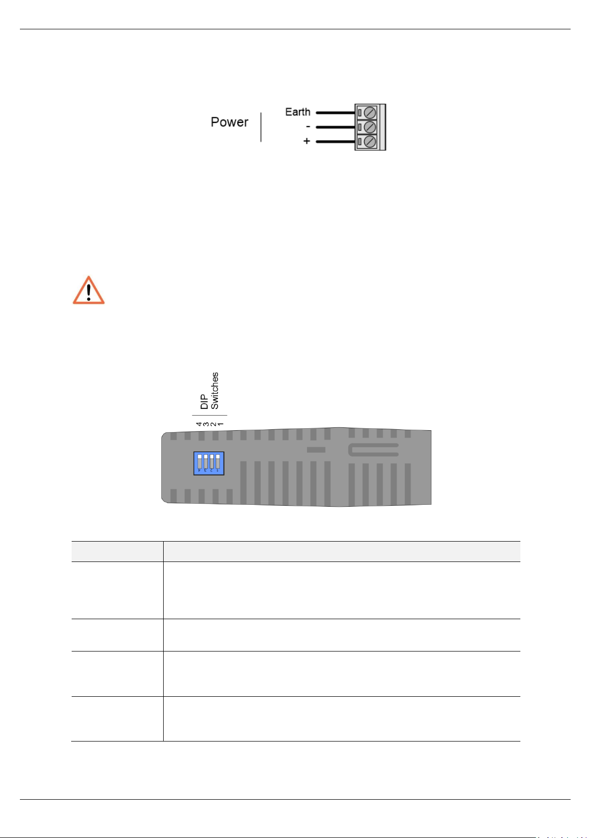
At the bottom of the PLX51-PBM module, there is one 3-way power connector.
Figure 2.2 – PLX51-PBM Power connector
The PLX51-PBM has an input voltage range of 10 to 36 VDC, applied to the module via the
power connector. The power connector also provides an Earth connection for the PLX51PBM.
NOTE: It is recommended to always have a good clean earth connected to the
module via the Earth connector on the power connector.
At the back of the module, there is slot for a SD memory card. The module provides four DIP
switches at the top of the enclosure as shown in the top view figure below.
Figure 2.3 – PLX51-PBM Top view
Table 2.1. - DIP Switch Settings
Page 14 of 162
Page 15

Installation
MODULE MOUNTING
The PLX51-PBM provides a DIN rail clip to mount onto a 35mm DIN rail.
Figure 2.4 - DIN rail specification
The DIN rail clip is mounted at the back of the module as shown in the figure below. Use a flat
screw driver to pull the clip downward. Once the module is mounted onto the DIN rail, the
clip must be pushed upwards to lock the module onto the DIN rail.
Figure 2.5 - DIN rail mouting
Page 15 of 162
Page 16

Installation
Pin
Signal
Description
1
-
Not connected
2
-
Not connected
3
RxD/TxD-P
Data received and transmit (+)
4
CNTR-P
Control signal to repeater (+)
5
DGND
Reference potential for +5Vdc
6
VP
+5Vdc for terminating resistors (active termination)
7
-
Not connected
8
RxD/TxD-N
Data received and transmit (-)
9
-
Not connected
PROFIBUS DP PORT (RS485)
The PROFIBUS DP port uses a female DB9 connector. This provides connection for the
communication conductors, cable shielding, and +5Vdc output power.
Figure 2.6 – PLX51-PBM PROFIBUS DP (RS485) DB9 connector
Table 2.2 – DB 9 Connector layout
Page 16 of 162
Page 17

Setup
3. SETUP
INSTALLING THE CONFIGURATION SOFTWARE
All PLX51-PBM network setup and configuration is done in the ProSoft PLX50 Configuration
Utility. This software can be downloaded from: www.prosoft-technology.com
Figure 3.1. - ProSoft PLX50 Configuration Utility Environment
Page 17 of 162
Page 18

Setup
NETWORK PARAMETERS
The PLX51-PBM has DHCP (Dynamic Host Configuration Protocol) enabled as factory default.
Thus, a DHCP server must be used to provide the module with the required network
parameters (IP address, subnet mask, etc.). There are a number of DHCP utilities available,
however it is recommended that the DHCP server in the PLX50 Configuration Utility is used.
Within the PLX50 Configuration Utility environment, the DHCP server can be found under the
Tools menu.
Figure 3.2. - Selecting DHCP Server
Once opened, the DHCP server listens on all available network adapters for DHCP requests
and display their corresponding MAC addresses.
Figure 3.3. - DHCP Server
NOTE: If the DHCP requests are not displayed in the DHCP Server, it may be
due to the local PC’s firewall. During installation, the necessary firewall rules
are automatically created for the Windows firewall. Another possibility is that
another DHCP Server is operational on the network and it has assigned the IP
address.
Page 18 of 162
Page 19

Setup
To assign an IP address, click on the corresponding ASSIGN button. The Assign IP Address for
MAC window opens.
Figure 3.4. - Assigning IP Address for MAC
The required IP address can be either entered, or a recently used IP address can be selected
by clicking on an item in the Recent list.
If the Enable Static checkbox is checked, the IP address will be set to static after the IP
assignment, thereby disabling future DHCP requests.
Once you click OK, the DHCP server will automatically assign the IP address to the module and
then read the Identity object product name from the device.
The successful assignment of the IP address by the device is indicated by the green
background of the associated row.
Figure 3.5. - Successful IP address assignment
It is possible to force the PLX51-PBM back into DHCP mode by powering up the device with
DIP switch 2 set to the On position.
Page 19 of 162
Page 20

Setup
A new IP address can then be assigned by repeating the previous steps.
NOTE: It is important to return DIP switch 2 back to Off position, to avoid the
module returning to a DHCP mode after the power is cycled again.
In addition to the setting the IP address, a number of other network parameters can be set
during the DHCP process. These settings can be viewed and edited in the PLX50 Configuration
Utility Application Settings, in the DHCP Server tab.
Once the DHCP process is complete, the network settings can be set using the Ethernet Port
Configuration via the Target Browser.
The Target Browser can be accessed under the Tools menu.
Figure 3.6. - Selecting the Target Browser
The Target Browser automatically scans the Ethernet network for EtherNet/IP devices.
Figure 3.7. - Target Browser
Page 20 of 162
Page 21

Setup
Right-clicking on a device, reveals the context menu, including the Port Configuration option.
Figure 3.8. - Selecting Port Configuration
The Ethernet port configuration parameters can be modified using the Ethernet Port
Configuration window.
Figure 3.9. - Port Configuration
Alternatively, these parameters can be modified using Rockwell Automation’s RSLinx
software.
Page 21 of 162
Page 22

Setup
GSD FILE MANAGEMENT
Each PROFIBUS device has a GSD file that is required to provide information needed to
configure the device for data exchange. The PLX50 Configuration Utility manages the GSD
library which is used for adding devices to the PLX51-PBM.
1 The GSD File Management Tool is opened by selecting GSD File Management under
the Tool menu in the configuration utility.
Figure 3.10 – Launching the GSD File Management Tool
2 Once the tool opens, a list of registered slave devices are displayed, using their GSD
files.
Figure 3.11 – GSD File Management Tool
Page 22 of 162
Page 23

Setup
3 To add a GSD file, select the Add option under the GSD File menu.
Figure 3.12 – GSD File Adding
4 Select the required GSD file and click OPEN.
Figure 3.13 – Adding GSD File
5 Once the file has been selected, the GSD File Management tool adds the slave device
to the device list and recompile the GSD catalog.
Page 23 of 162
Page 24

Setup
A GSD catalog can be exported from another PLX50 Configuration Utility by exporting the GSD
catalog from one PLX50 Configuration Utility, and importing it in another. This is done by
selecting either Import or Export under the Catalog menu as shown below:
Figure 3.14 – GSD Catalog import/export
Page 24 of 162
Page 25

Setup
CREATING A NEW PROJECT
1 Before you configure the module, a new PLX50 Configuration Utility project must be
created. Under the File menu, select New.
Figure 3.15 - Creating a new project
2 A PLX50 Configuration Utility Design Tool project is created, showing the Project
Explorer tree view. To save the project use the Save option under the File menu.
3 A new device can now be added by selecting Add under the Device menu.
Figure 3.16 - Adding a new device
Page 25 of 162
Page 26

Setup
4 In the Add New Device window, the PLX51-PBM and click the OK button.
Figure 3.17 – PLX51-PBM
5 The device appears in the Project Explorer tree and its configuration window opened.
The device configuration can be reopened by double-clicking the module in the Project
Explorer tree, or right-clicking the module and selecting Configuration.
Figure 3.18 – PLX51-PBM configuration
Page 26 of 162
Page 27

Setup
PLX51-PBM PARAMETERS
The PLX51-PBM parameters are configured by the PLX50 Configuration Utility.
Refer to the Additional Information section for documentation and installation links for
ProSoft’s PLX50 Configuration Utility.
GENERAL
The PLX51-PBM General configuration is opened by either double-clicking on the module in
the tree, or right-clicking the module and selecting Configuration.
Figure 3.19 – PLX51-PBM General configuration
Page 27 of 162
Page 28

Setup
Parameter
Description
Instance Name
This parameter is a user defined name to identify between various PLX51-PBM
modules.
Description
This parameter is used to provide a more detailed description of the application
for the module.
IP Address
The IP address of the module.
Mode
The PLX51-PBM can operate in one of three modes:
Quiet
This mode allows you to connect the PLX51-PBM to an active bus and run a DP
packet capture. In this mode, the PLX51-PBM will not communicate on the DP
Bus, but rather only listen.
Standalone Master
In this mode, the PLX51-PBM is the DP Master on the PROFIBUS network.
Slave
In this mode, the PLX51-PBM will emulate multiple PROFIBUS Slave devices.
Primary Interface
This is the network the PLX51-PBM will interface the PROFIBUS network.
EtherNet/IP (Logix)
The General configuration consists of the following parameters:
Table 3.1 - General configuration parameters
Page 28 of 162
Page 29

Setup
Parameter
Description
Basic Settings
Station Address (TS)
PROFIBUS Station Address for the PLX51-PBM module. TS should be unique on the
PROFIBUS network, it should also be less-than or equal to the HSA below:
Min: 0
Max: 126
Default: 1
Highest Address (HSA)
Highest Station Address. This is the highest station address of the active stations
(masters). Passive stations (slaves) can have a higher address than the HSA.
A low HSA is better for PROFIBUS performance.
Min: 1
Max: 126
Default: 126
Baud Rate
Baud Rate (in Kbps) of the PROFIBUS network: 9.6, 19.2, 45.45,
93.75, 187.5, 500, 1500, 3000, 6000 or 12000 Kbps. The baud rate should be
supported by all slaves in the configuration. The baud rate should be
selected depending on the cable length, see chapter “PROFIBUS DP”.
PROFIBUS – MASTER MODE
The PLX51-PBM PROFIBUS configuration is opened by either double-clicking on the module
in the tree, or right-clicking the module and selecting Configuration. Then select the
PROFIBUS tab.
Figure 3.20 – PLX51-PBM PROFIBUS configuration – Master mode
The PROFIBUS configuration consists of the following parameters:
Page 29 of 162
Page 30

Setup
Advanced Settings
Logix Comms Fail
Specifies the PROFIBUS Master behavior when losing communication with Logix,
either:
Force to Offline
Force to Clear
Logix Program Mode
Specifies the PROFIBUS Master behavior when Logix is set in Program mode, either:
Force to Offline
Force to Clear
Extra DPV1 Poll / Cycle
The number of additional DPV1 Polls (Class 2) per PROFIBUS Cycle.
Increasing this parameter results in faster Asset Management DTM updates.
Error Management
Token Retry Limit
Token Retry Limit is the number of times that a PROFIBUS Master tries to pass the
token before deciding that a station is not there. Value must be in the following
range:
Min: 0
Max: 15
Default: 3
Message Retry Limit
Message Retry Limit is the number of telegram repetitions if the address doesn’t
react. Value must be in the following range:
Min: 0
Max: 15
Default: 1
Timing
TTR
Target Rotation Time indicates the maximum time available for a token circulation
(time for PROFIBUS token to be passed to another master and be back). It takes in
account the number of slaves with their IO size (data exchanges telegram), different
telegrams needed and their duration times (FDL status, global control, pass token),
all mandatory timing with respect to the PROFIBUS standard (time slot, min and
max Tsdr, Tqui, Tset, …) and a safety margin which allows bandwidth for acyclic
messages (DPV1, …).
Min: 0
Max: 16777215
Slot Time (TSL)
Slot Time (in tbits) is the maximum time the PLX51-PBM will wait, after the
transmission of a request, for the reception of the first byte (Tchar) of an answer.
(It allows detecting a timeout.) It can be increased when repeaters are used in the
PROFIBUS network topology. The value must respect the rule:
Min: 37
Max: 16383
Gap Update Factor
Gap Update Factor: The range of addresses between 2 consecutive active stations
is called GAP. This GAP is submitted to a cyclic check during which the system
identifies the station condition (not ready, ready or passive).
Min: 1
Max: 100
Quiet Time (TQUI)
Quiet time (in tbits) is the time that a station may need to switch from sending to
receiving. It must respect the rule:
TQUI < MIN_TSDR
Min: 0
Max: 255
Page 30 of 162
Page 31

Setup
Setup Time (TSET)
Setup Time (in tbits) is the reaction time on an event. Calculation of TSET must
respect the rule:
Min: 1
Max: 494
PROFIBUS Cycle
PROFIBUS Cycle (in ms) (read/Write) field defines the cyclic time the master will
respect between two IO Data Exchange sequences. This parameter can be increased
when the PROFIBUS network load does not allow the processing of acyclic requests.
Auto Recommend
When enabled, all timing parameters will be updated with recommended
calculations when clicking Ok or Apply.
NOTE: When the BAUD Rate is changed, all PROFIBUS timing
parameters will be updated irrespective of the Auto Recommend
check-box selection.
Default Watchdog
(Read-Only)
Default Devices Watchdog (in ms) value defines the watchdog value assigned by
default to all devices in the configuration.
Min TSDR
(Read-Only)
Smallest Station (in tbits) is the minimum time that a PROFIBUS DP slave must wait
before it may answer. It must respect the rule:
TQUI < MIN_TSDR
Min: 11
Max: 1023
Max TSDR
(Read-Only)
Largest Station (in tbits) is the maximum time that a PROFIBUS DP slave may take
in order to answer. Calculation of MAX_TSDR must respect the rule:
Min: 37
Max: 65525
Idle Time 1 (Tid1)
(Read-Only)
Time Idle1 (in tbits) is the time between the acknowledgement frame or token
frame reception and the transmission of the next frame.
Tid1 = Max(Tsyn+Tsm, MIN_TSDR)
with
Tsyn= 33
Tsm= 2 + 2* TSET + TQUI
Idle Time 2 (Tid2)
(Read-Only)
Time Idel2 (in tbits) is the time between the transmission of an unconfirmed packet
and the transmission of the next packet.
Tid2 = Max (Tsyn+Tsm, MAX_TSDR)
with
Tsyn= 33
Tsm= 2 + 2* TSET + TQUI
Table 3.2 - PROFIBUS configuration parameters
NOTE: When the BAUD Rate is changed, all the PROFIBUS timing parameters
will change to the default values for that specific BAUD Rate.
Page 31 of 162
Page 32

Setup
Parameter
Description
BAUD Rate
Baud Rate (in Kbps) of the PROFIBUS network: 9.6, 19.2, 45.45,
93.75, 187.5, 500, 1500, 3000, 6000 or 12000 Kbps. The baud rate should be
selected depending on the cable length, see chapter “PROFIBUS DP”
PROFIBUS – SLAVE MODE
The PLX51-PBM PROFIBUS configuration is opened by either double-clicking on the module
in the tree, or right-clicking the module and selecting Configuration. Then select the
PROFIBUS tab.
Figure 3.21 – PLX51-PBM PROFIBUS configuration – Slave mode
The PROFIBUS configuration consists of the following parameters:
Table 3.3 - PROFIBUS configuration parameters – Slave Mode
Page 32 of 162
Page 33

Setup
Parameter
Description
EtherNet/IP Connections
The number of EtherNet/IP (CIP) Connections to be used in the exchange with
Logix (1 to 4).
Note, this value must match that configured in the Logix IO tree.
Controller Path
This is the CIP path to the Logix controller.
In PROFIBUS Slave Mode, this path will be used for the Class 3 data exchanges
for DPV1 objects and alarms.
Note: This path can be either entered manually, or configured using the Target
Browser.
Response Timeout
The maximum time (ms) allowed for a Class 3 response from the Logix
controller. Default: 5000 ms.
LOGIX
This section is used when the Primary Interface is set to EtherNet/IP.
The PLX51-PBM Logix configuration is opened by either double-clicking on the module in the
tree, or right-clicking the module and selecting Configuration. Then select the Logix tab.
Figure 3.22 – PLX51-PBM Logix configuration
The Logix configuration consists of the following parameters:
Table 3.4 - Logix configuration parameters
Page 33 of 162
Page 34

Setup
To browse to a controller path, select the BROWSE… button to open the Target Browser.
Then select a Logix controller and click Ok. The path updates automatically.
Figure 3.23 – Target Browser – Selecting Logix controller
Page 34 of 162
Page 35

Setup
Parameter
Description
DLR Enable
This must be set to enable Device Level Ring operation when the PLX51PBM is operating in an Ethernet DLR.
NTP Enable
The PLX51-PBM can synchronize its onboard clock to an NTP Server by
enabling NTP.
NTP – Server IP Address
This setting is the IP address of the NTP Server which will be used as a
time source.
NTP – Update Interval
This setting is the updated interval (in seconds) that the PLX51-PBM will
request time from the NTP Server.
ADVANCED
The PLX51-PBM Advanced configuration is opened by either double-clicking on the module in
the tree, or right-clicking the module and selecting Configuration. Then select the Advanced
tab.
Figure 3.24 – PLX51-PBM Advanced configuration
The Advanced configuration consists of the following parameters:
Table 3.5 - Advanced configuration parameters
Page 35 of 162
Page 36

Setup
MODULE DOWNLOAD
Once the PLX51-PBM configuration is complete, it must be downloaded to the module. The
configured IP address of the module is used to connect to the module.
1 To initiate the download, right-click on the module and select the Download option.
Figure 3.25 - Selecting Download
2 Once complete, you will be notified that the download was successful.
Figure 3.26 - Successful download
Page 36 of 162
Page 37

Setup
3 Within the PLX50 Configuration Utility environment, the module will be in the Online
state, indicated by the green circle around the module icon. The module is now
configured and will start operating immediately.
Figure 3.27 - Module online
Page 37 of 162
Page 38

Setup
DEVICE DISCOVERY (ONLINE) – MASTER MODE
Once online with the PLX51-PBM in the PLX50 Configuration Utility, you will be able to scan
the PROFIBUS network for slave devices.
NOTE: If the incorrect PROFIBUS parameters have been configured (e.g. BAUD
rate) it will result in the PLX51-PBM not seeing any slave devices on the
PROFIBUS network.
DISCOVERY
1 The slave device discovery can be found by selecting the Discovered Nodes tab in the
PLX51-PBM Status window.
Figure 3.28 –Device Discovery
2 To start a new device discovery, click the START DISCOVERY button. Once the scan is
complete, the detected slave devices are listed.
NOTE: The time to scan the bus depends on the BAUD Rate selected. The
higher the BAUD rate, the faster the bus discovery scan time.
Figure 3.29 –Devices Found
Page 38 of 162
Page 39

Setup
3 If a device has been found not currently in the PLX51-PBM configured device list, you
will be able to add the device from this window by right-clicking on the device and
selecting Add Device.
NOTE: The GSD file will need registered before a device can be added to the
PLX51-PBM configuration.
Figure 3.30 – Adding discovered Field Devices
4 Select the GSD file to add the device to the PLX51-PBM configured device list.
Figure 3.31 – Selecting the GSD for the slave device
5 Once the devices have been configured (as well as the correct mapping is in Logix), the
devices will show up as exchanging data.
Figure 3.32 – Discovering running devices
Page 39 of 162
Page 40

Setup
DEVICE STATION ADDRESS CHANGE
Certain devices can be set up to allow remotely changing of the station address. Devices with
this option set general defaults to station address 126.
1 You can change the station address of a device (if the device is correctly set up) by
right-clicking on the device in the Discovery list and selecting Change Station Address.
Figure 3.33 – Changing Station Address
2 Select the new station address for the device. Click the SET button.
Figure 3.34 – Changing the Station Address.
3 Once the request has been sent, you can either start a new network discovery to
confirm the address has changed or monitor the Livelist (see the Diagnostics section).
NOTE: The amount of time for the device to appear at the new station address
is device-dependant. In the Livelist, there is a period where both node
addresses show up while the original station address is timing out.
NOTE: If the station address is set to an address that is already present on the
DP network, it will result in communication failure of both devices.
NOTE: Generally, the device will need to be in the correct state before it will
accept a command to change its station address (i.e. must not be in data
exchange state).
Page 40 of 162
Page 41

Setup
ADDING PROFIBUS DP DEVICES – MASTER MODE
1 Add each PROFIBUS device to the PLX51-PBM by right-clicking on PROFIBUS Devices
in the tree and selecting Add PROFIBUS Device.
Figure 3.35 – Adding a PROFIBUS Field Device
2 Select the device to be added to the PLX51-PBM. This is done by selecting the device
from the GSD File Selector and click OK.
Figure 3.36 – Selecting a PROFIBUS Field Device
Page 41 of 162
Page 42

Setup
Parameter
Description
Instance Name
The device instance name which will be used to create the Tag names
and UDTs in Logix.
3 Once the device has been added, the General Configuration page opens and the device
is added at the first open PROFIBUS Station Address.
Figure 3.37 – PROFIBUS Field Device Added
GENERAL
The Device Configuration is opened by either double-clicking on the slave device in the tree,
or right-clicking the slave device and selecting Configuration.
Figure 3.38 – General configuration parameters
The General configuration consists of the following parameters:
Table 3.6 –Device General configuration parameters
Page 42 of 162
Page 43

Setup
Parameter
Description
Node Address
This is the station address configured for the added device. This is the address the PLX51PBM will use to look for and configure the device for Data Exchange.
TSDR
This parameter is the minimum time that a PROFIBUS-DP slave must wait before it
responds. It must respect the rule:
Min: 11
Max: 1023
Default: 11
Minimum Slave
Interval
This is the minimal time that the PROFIBUS must wait between two I/O data exchanges
with this device. The default value proposed comes from the GSD File.
Min: 1
Max: 65535
Watchdog
Enable
Enables the watchdog for the slave device data exchange. The slave device monitors the
data exchange rate (PROFIBUS Cycle) and it must be less than the Watchdog Value else
the slave device will change back into an unconfigured state.
Watchdog Value
Used to monitor cyclic communication and must be significantly higher than the time
required for one PROFIBUS cycle. If a slave does not receive a request frame for a period
of time longer than the watchdog time, it will revert to its initial, power-up state and cyclic
communication will have to be reestablished.
The minimum and default values are defined by the PLX51-PBM Default Watchdog setting
in the PLX51-PBM PROFIBUS configuration.
Group
Membership
Specifies which groups the slave belongs to. A slave can be in multiple groups at a time
(from 1 through 8). Groups are used by the master when it sends a Sync or Freeze
command. PROFIBUS Group checkboxes are enabled when Sync Mode or Freeze Mode
checkboxes are checked.
Freeze Enabled
User data transmission Synchronization control commands enable the synchronization of
inputs. Freeze Mode field is unchecked by default.
Sync Enabled
User data transmission Synchronization control commands enable the synchronization of
outputs. Sync Mode is unchecked by default.
PROFIBUS CONFIGURATION
The PROFIBUS configuration is opened by either double-clicking on the slave device in the
tree, or right-clicking the slave device and selecting Configuration. Then select the Profibus
Configuration tab.
Figure 3.39 – Field Device PROFIBUS configuration parameters
The PROFIBUS configuration consists of the following parameters:
Table 3.7 – Field Device PROFIBUS configuration parameters
Page 43 of 162
Page 44

Setup
DPV1
The slave device DPV1 configuration is opened by either double-clicking on the slave device
in the tree, or right-clicking the slave device and selecting Configuration. Then select the DPV1
tab.
Figure 3.40 – DPV1 configuration parameters
Page 44 of 162
Page 45

Setup
Parameter
Description
Enable DPV1
Indicates if the slave supports DPV1 Class 1 access (read and write) or
alarms. If the device does not support these DPV1 services, this
parameter must be unchecked. The default value is based on the
information provided by the GSD File.
Base 1ms
Indicates if the device should use the 1ms base time for watchdog time
calculation. See the “PROFIBUS Settings” chapter for watchdog time
calculation.
By default, the field is unchecked which sets the watchdog base to 10 ms.
Note: The watchdog value is always shown in the configuration panel in ms
regardless of this time base setting.
Enable Fail Safe
The Fail Safe mode determines the behavior of the DP Slave outputs when
the PROFIBUS Master is in CLEAR state:
If the slave is configured to be Fail Safe mode and supports this
feature, then it will apply its own fallback value (the Master sends
outputs with 0 length data).
If not, the Master sends output data at 0.
If this feature is supported by the device, the check box must be checked.
If the device does not support it, this parameter must be unchecked. The
default value is based on the information provided by the GSD File.
Check Config
This parameter defines the reaction to the reception of configuration data.
If the check box is not set, the check is as described in EN 50170.
If the check box is set, the check is made according to a specific user
definition. By default, the field is unchecked.
Alarm Mode
This parameter specifies the maximum number of possible active alarms
for the device.
Alarm Ack uses SAP50
This parameter forces the PLX51-PBM to use Service Access Point (SAP) 50
to acknowledge alarms.
Alarm Enables
Enables specific alarms for the slave device to report.
The available alarms are only available if specified in the device’s GSD file:
Pull Plug Alarm
Process Alarm
Diagnostic Alarm
Manufacturer Alarm
Status Alarm
Update Alarm
The DPV1 configuration consists of the following parameters:
Table 3.8 – DPV1 configuration parameters
Page 45 of 162
Page 46

Setup
USER PARAMETERS
The User Parameters configuration is opened by either double-clicking on the slave device in
the tree, or right-clicking the slave device and selecting Configuration. Then select the User
Parameters tab.
Figure 3.41 – Device User Parameter configuration parameters
The User Parameters configuration consists of the device-specific user configuration. This is
extracted from the device GSD file and can be used to configure its parameters. When one of
the parameters is changed, the User Parameters data is updated, which is sent to the device
in the Set Parameter telegram.
Page 46 of 162
Page 47

Setup
SLOT CONFIGURATION
Each slave device can have multiple slots configured. A slot can be a placeholder for a process
variable or a placeholder for a specific piece of hardware. In the example below, the added
PROFIBUS slave device is an I/O adapter that can have multiple additional I/O modules, which
will be represented as additional slots.
Figure 3.42 – Field Device Slot Configuration
1 To add a module, click the ADD MODULE button. The Add Module window lists the
available modules from the GSD file.
Figure 3.43 – Module Selection
2 The Module Description filter can be used to easily locate the required module. Once
the module has been selected, click the OK button.
Page 47 of 162
Page 48

Setup
3 The module is added to the Slot Configuration.
Figure 3.44 – Slot configuration – (Logix)
SLOT CONFIGURATION - MODULES
Each added module can consist of one or more Data Points. In the example below, the module
has two Data Points; one Input and one Output.
The description of each is based on the module name (from GSD file), but can be edited. When
using Logix, the Description is used to create the member of the device-specific UDTs.
Therefore, no illegal Logix characters are permitted. It is also important that these
descriptions are unique within a device.
Figure 3.45 – Slot descriptions
Some modules provide module-specific User Parameters to further configure the module.
1 These parameters can be accessed by either clicking on the Configure (…) button or
by right-clicking on the Module and selecting the Configure Module option in the
context menu.
Figure 3.46 – Accessing Module-Specific User Parameters
Page 48 of 162
Page 49

Setup
2 The Module User Parameter Editor window opens. The parameters and their
enumerated options are derived from the GSD file.
Figure 3.47 – Device Slot configuration additional parameters
3 Once the slot parameters have been updated, click OK. This updates the Extended User
Parameters and return to the Slot Configuration page.
When adding a slot, the data format and size defaults to that of the selected module in the
GSD file. Depending on the GSD file, the default configuration may not be preferred and can
be changed.
Page 49 of 162
Page 50

Setup
DATA POINTS
Formatting the modules data can be achieved by a combination of adding or removing Data
Points and changing the Data Type of each.
Data Points can be added by either right-clicking on the module and selecting Add Data Point
or by clicking on the “+” button.
Data Points can be removed by either right-clicking on the module and selecting Delete Data
Point or by clicking on the “X” button.
Figure 3.48 – Adding / Removing Data Points
NOTE: Each module must contain at least one Data Point.
After adding a new Data Point, the following should be configured:
Description
Data Point Type (Input, Output, None)
Data Type
Byte Length
Figure 3.49 – Configuring Data Points
After updating the Data Type, the Byte Length is set to match the selected Data Type. By
modifying the Byte Length thereafter, an array of that Data Type can be configured. It is
important that the Byte Length is always a multiple of the base Data Length.
Page 50 of 162
Page 51

Setup
Data Type
Byte Length MUST be a multiple of:
BOOL
1
SINT
1
INT
2
DINT
4
REAL
4
Table 3.9 – Data Type – Byte Length Restrictions
NOTE: It is critical that the configured Byte Length be a multiple of the base
Data Type.
NOTE: It is critical that the total sum of input and output bytes (of all the Data
Points) match that required by the slave device. If not, this could cause
unexpected results.
NOTE: The DP (Byte) Offset for each Data Point is automatically calculated.
Page 51 of 162
Page 52

Setup
SLOT CONFIGURATION – LOGIX SPECIFIC
When using Logix as the Primary Interface, the PROFIBUS Data Points are packed and padded
to match a device-specific UDT. All the Inputs are collated together, then all the Outputs.
NOTE: It is important that the Data Point Descriptions do not contain any illegal
characters and are not duplicated within a device. Failing to do so will create
errors when generating and importing the mapping .L5X into Studio 5000.
Figure 3.50 – Slot configuration – Logix Example
START-UP PARAMETERS
Each slave device can have a set of start-up parameters associated with it. These are updated
once Data Exchange is active using DPV1 Class 1 messaging. Thus, you can have specific
parameters that must be updated after the device is initialized for data exchange, which
simplifies device replacement.
Figure 3.51 – Start-up Parameters
Enable the start-up parameters by selecting the Enable Start-Up Parameters checkbox. Then
enter the required start-up parameters, as shown in the example below.
Figure 3.52 – Start-up Parameters Example
Once the slave device has been successfully parameterized and configured for Data Exchange,
the PLX51-PBM updates one parameter at a time for each slave device.
Page 52 of 162
Page 53

Setup
Module
GSD Filename
PLX51-PBM
PSFTS10FE.GSD
ADDING PROFIBUS DP DEVICES – SLAVE MODE
Adding PROFIBUS devices to the PLX51-PBM is done by right-clicking on PROFIBUS Devices in
the tree and selecting ADD PROFIBUS DEVICE.
Figure 3.53 – Adding a PROFIBUS Field Device
When adding a PROFIBUS Device in Slave Mode, a static PLX51-PBM GSD file is automatically
applied.
Table 3.10 – Slave GSD Files
Page 53 of 162
Page 54

Setup
Parameter
Description
Instance Name
The device instance name which will be used to create the Tag names
and UDTs in Logix.
GENERAL
The PLX51-PBM slave feature Device Configuration window is opened by either doubleclicking on the slave device in the tree, or right-clicking the slave device and selecting
Configuration.
Figure 3.54 – General parameters
The General configuration consists of the following parameters:
Table 3.11 –Device General configuration parameters
Page 54 of 162
Page 55

Setup
Parameter
Description
Node Address
This is the station address configured for the added device. This is the
address the PLX51-PBM will use to look for and configure the device for
Data Exchange.
TSDR
N/A
Minimum Slave Interval
N/A
Watchdog Enable
N/A
Watchdog Value
N/A
Group Membership
N/A
PROFIBUS CONFIGURATION
The PLX51-PBM slave feature PROFIBUS Configuration is opened by either double-clicking on
the slave device in the tree, or right-clicking the slave device and selecting Configuration. Then
select the Profibus Configuration tab.
Figure 3.55 – PROFIBUS Configuration parameters
The PROFIBUS configuration consists of the following parameters:
Table 3.12 – PROFIBUS configuration parameters
Page 55 of 162
Page 56

Setup
Parameter
Description
Enable DPV1
Indicates if the slave supports DPV1 Class 1 access (read and write) or
alarms. If the device does not support these DPV1 services, this
parameter must be unchecked. The default value is based on the
information provided by the GSD File.
Base 1ms
N/A
Enable Fail Safe
N/A
Check Config
N/A
Alarm Mode
N/A
Alarm Ack uses SAP50
This will force the PLX51-PBM to use Service Access Point (SAP) 50 to
acknowledge alarms.
Alarm Enables
N/A
DPV1
The PLX51-PBM slave feature DPV1 configuration is opened by either double-clicking on the
slave device in the tree, or right-clicking the slave device and selecting Configuration. Then
select the DPV1 tab.
Figure 3.56 – DPV1 parameters
The DPV1 configuration consists of the following parameters:
Table 3.13 – DPV1 configuration parameters
Page 56 of 162
Page 57

Setup
Parameter
Description
Slot
The Slot number to which the PROFIBUS DP transaction will be directed.
Index
The Index number to which the PROFIBUS DP transaction will be directed.
Size
The size (bytes) of the transaction.
Functions
The Functions supported by the Slave device for this object:
Read
Write
Read/Write
Tagname
The Logix Tagname where the data will be read / written.
SLOT CONFIGURATION
The PLX51-PBM slave feature Slot configuration is the same as the Master Mode. See section
3.8.5.
DPV1 OBJECTS
The PLX51-PBM slave feature DPV1 Objects configuration window is opened by either double-
clicking on the slave device in the tree, or right-clicking the slave device and selecting
Configuration. Then select the DPV1 Objects tab.
Figure 3.57 – Device DPV1 Objects parameters – Logix
The DPV1 configuration consists of the following parameters:
Table 3.14 – Device DPV1 Objects configuration parameters
Page 57 of 162
Page 58

Setup
The Logix Tagname can be either entered manually or selected using the Logix Tag Browser
by clicking on the Browse button (…) adjacent to the Tagname.
NOTE: The Logix controller path must be correctly set for the tags to display in
the browser.
Figure 3.58 – Device DPV1 Objects Tag Browsing
Page 58 of 162
Page 59

Setup
Parameter
Description
Size
The size (bytes) of the Alarm object.
Tagname
The Logix Tagname from where the alarm data will be read. (Logix Only)
DPV1 ALARMS
The PLX51-PBM slave feature DPV1 Alarms window is opened by either double-clicking on the
slave device in the tree, or right-clicking the slave device and selecting Configuration. Then
select the DPV1 Alarms tab.
NOTE: The Size of the DPV1 Alarm must be greater than 4 or the alarm
triggering will not execute.
Figure 3.59 – PV1 Alarms parameters (Logix)
The DPV1 configuration consists of the following parameters:
Table 3.15 – Device DPV1 Alarms configuration parameters
NOTE: The DP Master connected to the PLX51-PBM (in slave mode) will be able
to configure the following alarms:
Diagnostic Alarm
Process Alarm
Pull Plug Alarm
Status Alarm
Update Alarm
Manufacturer Specific Alarm
Page 59 of 162
Page 60

Setup
LOGIX CONFIGURATION
The PLX51-PBM can be easily integrated with Allen-Bradley Logix family of controllers.
Integration with the Logix family in Studio5000 makes use of the EDS Add-On-Profile (AOP) or
a Generic Module Profile.
EDS AOP (LOGIX V21+)
Before the module can be added to the tree, the PLX51-PBM’s EDS file must be registered.
Using RSLinx, the EDS file can be uploaded from the device. The EDS file can also be
downloaded from the product web page at www.prosoft-technology.com. The EDS file is then
registered manually using the EDS Hardware Installation Tool shortcut under the Tools menu
in Studio 5000.
Figure 3.60 - EDS Hardware Installation Utility
After the EDS file has been registered, the PLX51-PBM can be added to the Logix I/O tree in
Studio 5000.
Page 60 of 162
Page 61

Setup
1 Under a suitable Ethernet bridge module in the tree, select the Ethernet network,
right-click and select the NEW MODULE option.
Figure 3.61 – Adding a module
2 The Select Module Type window opens. To easily search for the module, use the
Vendor filter to select only the ProSoft Technology modules as shown in the figure
below.
Figure 3.62 – Selecting the module
Page 61 of 162
Page 62

Setup
3 Locate and select the PLX51-PBM module and click the CREATE button. The New
Module window opens, where you must specify the Name and IP address to complete
the instantiation.
Figure 3.63 – Module instantiation
4 Once the instantiation is complete, the module appears in the Logix I/O tree.
Figure 3.64 – Logix IO tree
5 The Module Defined Data Types are automatically created during the instantiation
process. These data types provide meaningful structures to the module data. An
excerpt of the Input Image is shown in the following figure.
Figure 3.65 – Module Defined Data Type
Page 62 of 162
Page 63

Setup
GENERIC MODULE PROFILE (LOGIX PRE-V21)
NOTE: When using a Generic Module Profile, you will need to modify the code
generated by the PLX50 Configuration Utility (see Logix Mapping) to match the
single connection profile. To do this, you must remove the connection number
from the Source and Destination tag in the copy blocks (as shown in the
example below).
Figure 3.66 – Generated Logix Routine from PLX50 Configuration Utility (highlight
connection number)
Figure 3.67 – Modified Logix Routine from PLX50 Configuration Utility for Generic Module
Profile
1 When using Logix versions prior to version 21, the PLX51-PBM module must be added
to the RSLogix 5000 I/O tree as a Generic Ethernet Module. This is achieved by rightclicking on the Ethernet Bridge in the RSLogix 5000 and selecting New Module. Select
ETHERNET-MODULE and click OK.
NOTE: See the next section for importing the configuration (.L5X).
Figure 3.68 – Adding a Generic Ethernet Module in RSLogix 5000
Page 63 of 162
Page 64

Setup
Connection Parameter
Assembly Instance
Size
Input
132
500 (8-bit)
Output
133
496 (8-bit)
Configuration
102
0 (8-bit)
2 Enter the IP address, Input, Output, and Configuration parameters of the PLX51-PBM.
The required connection parameters for the PLX51-PBM module are shown below:
Table 3.16 - RSLogix class 1 connection parameters for the PLX51-PBM module
Figure 3.69 - General module properties for PLX51-PBM
3 In the Connection tab of the Module Properties window, enter the Requested Packet
Interval (RPI). This is the rate at which the input and output assemblies are exchanged
in milliseconds. Refer to the Technical Specification section for further details on the
limits of the RPI.
Figure 3.70 - Connection module properties in RSLogix 5000
Page 64 of 162
Page 65

Setup
4 Once the PLX51-PBM has been added to the RSLogix 5000 I/O tree, the Logix controller
is ready to connect to the PLX51-PBM with a Class 1 connection.
Figure 3.71 – RSLogix 5000 I/O module tree
MULTI-CONNECTION
The PLX51-PBM supports up to four Class 1 (cyclic data exchange) connections. This allows
for more field device connections per PLX51-PBM because more data can be exchanged
between the Logix controller and the PLX51-PBM.
NOTE: This only applies when you have implemented the PLX51-PBM into
Logix using an EDS AOP. When using a Generic Module Profile in Logix (preLogix v21), you will only be able to use 1 Logix Connection.
When you verify the PLX50 Configuration Utility project (this is done by right-clicking on the
device and selecting VERIFY CONFIGURATION), the software indicates if all the current
configuration will fit into the selected EtherNet/IP Connection count. If not, you will need to
increase the connection count.
In the PLX50 Configuration Utility, you can set the number of EtherNet/IP Connections in the
Logix tab of the configuration window (as shown below):
Figure 3.72 – PLX50 Configuration Utility EtherNet/IP Connection Count
Page 65 of 162
Page 66

Setup
In Logix, you can increase/decrease the connection count using the EDS AOP (as shown
below):
Figure 3.73 – Logix EtherNet/IP Connection Count
Page 66 of 162
Page 67

Setup
LOGIX MAPPING
The PLX50 Configuration Utility generates the required UDTs and Routines (based on the
PLX51-PBM configuration) to map the required PROFIBUS Slave input and output data.
1 Generate the required Logix and UDTs by right-clicking on the module’s icon in the
PLX50 Configuration Utility and selecting the GENERATE LOGIX L5X option.
Figure 3.74 – Selecting Generate Logix L5X
2 Select a suitable file name and path for the L5X file.
Figure 3.75 – Selecting the Logix L5X file name
Page 67 of 162
Page 68

Setup
3 This L5X file can now be imported in to the Studio 5000 project. Right-click on a
suitable Program and select ADD, and then click IMPORT ROUTINE.
Figure 3.76 – Importing the L5X file into Studio 5000
4 In the File Open window, select the L5X file and click OK.
5 Since the imported mapping routine is not a Main Routine, it will need to be called
from the current Main Routine using a JSR.
Figure 3.77 – Calling the mapping routine
6 The import creates the following:
Mapping Routine
Multiple UDT (User-Defined Data Types)
Multiple Controller Tags
Page 68 of 162
Page 69

Setup
Figure 3.78 – Imported Logix Objects
A number of PLX51 specific (UDT) tags are created as shown above.
The Master Control tag is used to set the PROFIBUS Mode and to Enable the individual Slave
Devices.
Figure 3.79 – Master Control tag
Page 69 of 162
Page 70

Setup
The Master Status tag displays the status of the PROFIBUS Master, including arrays to show
the LiveList, Data Exchange Active, Alarm, and Diagnostic pending status of each slave device.
Figure 3.80 – Master Status tag
There is also a tag created for each configured slave device. The structure of which comprises
of the following:
Input Status - Status related to slave device
Input Data - As specified in the Input Data Points in the Slot configuration
Output Control - Used to trigger alarms
Output Data - As specified in the Output Data Points in the Slot configuration
Figure 3.81 – Slave Device-Specific tag
Page 70 of 162
Page 71

Operation
4. OPERATION
LOGIX OPERATION
The PLX51-PBM can exchange data with a Logix controller by establishing a Class 1
connection.
PROFIBUS DP - MASTER
Once the PLX51-PBM and Logix controller have been correctly configured, the PLX51-PBM can
exchange data with PROFIBUS slave devices.
NOTE: The module input and output assembly of each connection is an
unpopulated array of data. The imported Logix routine (generated by PLX50
Configuration Utility) copies this data to the input and output assemblies.
MASTER STATUS
Below are the definitions for the Master Status UDT tags created by the PLX50 Configuration
Utility.
Figure 4.1 – Master Status tags
Page 71 of 162
Page 72

Operation
Tag
Description
ConfigValid
Configuration has been downloaded to the PLX51-PBM and is being executed.
1 – PLX51-PBM has been successfully configured.
0 – PLX51-PBM is not configured.
Owned
Indicates if the PLX51-PBM is owned by a Logix Controller with a connection count
similar to what has been configured in the PLX50 Configuration Utility.
1 – PLX51-PBM is connected.
0 – PLX51-PBM is not connected.
DuplicateDPStation
Indicates that the PLX51-PBM has detected another PROFIBUS DP station with
the same station address as itself and has entered a temporary Back-off mode.
1 – Duplicate detected (Back-off mode active).
0 – Normal (No duplicate detected).
NOTE: In this condition, the PLX51-PBM will not
communicate on the PROFIBUS DP network. Although the
back-off time is approximately 5 seconds, should the
conflicting DP master remain active on the PROFIBUS
network, the PLX51-PBM will continuously re-enter the
back-off mode.
PROFIBUSFieldbusError
There is a PROFIBUS network issue (e.g. cable unplugged, under/over terminated,
etc.).
1 – Fieldbus error detected.
0 – Normal (No errors detected).
PROFIBUSDeviceError
At least one slave device has a communication issue (e.g. offline, not exchanging
process data, etc.)
1 – Device error detected.
0 – Normal (No errors detected).
PROFIBUSOffline
The PROFIBUS network is offline and the PLX51-PBM will not communicate on
the network.
1 – PROFIBUS fieldbus state is OFFLINE.
0 – PROFIBUS fieldbus state is not OFFLINE.
PROFIBUSStopped
The PROFIBUS network is running and the PLX51-PBM is communicating on the
network, but it will not exchange any process data with any slave device.
1 – PROFIBUS fieldbus state is STOPPED.
0 – PROFIBUS fieldbus state is not STOPPED.
PROFIBUSClear
The PROFIBUS network is running and the PLX51-PBM is communicating with all
slave devices on the network, and if configured in the PLX51-PBM, the module
will configure and exchange process data with each slave device. NOTE: In CLEAR
mode the PLX51-PBM will not send any output data to any slave device.
1 – PROFIBUS fieldbus state is CLEAR.
0 – PROFIBUS fieldbus state is not CLEAR.
PROFIBUSOperational
The PROFIBUS network is running and the PLX51-PBM is communicating with all
slave devices on the network, and if configured in the PLX51-PBM, the module
will configure and exchange process data with each slave device.
Page 72 of 162
Page 73

Operation
1 – PROFIBUS fieldbus state is operational.
0 – PROFIBUS fieldbus state is not operational.
SlaveMode
When in Slave mode, the PLX51-PBM will emulate multiple PROFIBUS Slave
devices.
1 – The PLX51-PBM is in PROFIBUS Slave Mode.
0 – The PLX51-PBM is not in PROFIBUS Slave Mode.
ConfigCRC
The signature of the configuration currently executing on the module.
DeviceLiveList
Indicates the nodes that are online on the local PROFIBUS network. Each bit
represents a node.
When the bit is set to ‘1’, the device is online.
When the bit is off ‘0’, the device is not on the PROFIBUS network.
Bit 0 – Node 0 Online
Bit 1 – Node 1 Online
……….
Bit 126 – Node 126 Online
DeviceDataExchange
Active
Indicates the nodes that are online and exchanging DPV0 data on the local
PROFIBUS network. Each bit represents a node.
When the bit is set to ‘1’, the device is online and exchanging data.
When the bit is set to ‘0’, the device is not exchanging data on the PROFIBUS
network.
Bit 0 – Node 0 Exchanging DPV0 Data
Bit 1 – Node 1 Exchanging DPV0 Data
……….
Bit 126 – Node 126 Exchanging DPV0 Data
DeviceAlarmPendingFlags
Indicates the nodes that have an alarm pending on the local PROFIBUS network.
Each bit represents a node.
When the bit is set to ‘1’, the device has an alarm pending that must be unloaded.
When the bit is set to ‘0’, the device does not have an alarm pending.
Bit 0 – Node 0 has an alarm pending
Bit 1 – Node 1 has an alarm pending
……….
Bit 126 – Node 126 has an alarm pending
DeviceDiagnosticPending
Flags
Indicates the nodes that have diagnostics pending on the local PROFIBUS
network. Each bit represents a node.
When the bit is set to ‘1’, then the device has diagnostics pending that must be
unloaded.
When the bit is set to ‘0’, the device does not have any diagnostics pending.
Bit 0 – Node 0 has diagnostics pending
Bit 1 – Node 1 has diagnostics pending
……….
Bit 126 – Node 126 has diagnostics pending
Table 4.1 – Logix Master Status tags
Page 73 of 162
Page 74

Operation
Tag
Description
MasterControl
This tag is used to set the state of the fieldbus network.
0 – Set PROFIBUS network state to OFFLINE
1 – Set PROFIBUS network state to STOP
2 – Set PROFIBUS network state to CLEAR
3 – Set PROFIBUS network state to OPERATIONAL
RedundancyControl
Reserved
DeviceEnable
These bits enable nodes on the PROFIBUS network for data exchange. Each
bit represents a node.
When the bit is set to ‘1’, the device (if configured) will exchange data with
the PLX51-PBM
When the bit is set to ‘0’, the device does exchange data with the PLX51-PBM.
Bit 0 – Node 0 is enabled for data exchange
Bit 1 – Node 1 is enabled for data exchange
……….
Bit 126 – Node 126 is enabled for data exchange
MASTER CONTROL
Set the PROFIBUS Operating mode from the PLX51-PBM Logix output assembly in the Logix
controller.
Figure 4.2 – Master Control tags
Table 4.2 – Master Control tags
You will be able to see if there are any faults (e.g. configured device not found) by viewing the
LEDs of the PLX51-PBM (see the Diagnostics section), by going online with the module in the
PLX50 Configuration Utility and viewing the PLX51-PBM Master and Device Diagnostics, or by
viewing the input assembly of the PLX51-PBM in Logix.
STATUS AND DPV0 DATA EXCHANGE
Page 74 of 162
Page 75

Operation
Tag
Description
Status
Online
Indicates if the device is online on the PROFIBUS network.
1 – Device is online
0 – Device is not online
DataExchangeActive
Indicates if the device is configured and exchanging data on the
PROFIBUS network.
1 – Device is active and exchanging data
0 – Device is not exchanging data
You must ensure that all application code making use of data from a
slave device first checks that the DataExchangeActive bit is 1.
IdentMismatch
Indicates if the device configured in the PLX50 Configuration Utility
and the device at the configured node address do not match because
they have different ident numbers.
1 – Online device Ident does not match configured device
0 – Online device and configured device ident match
DisabledByOutputAssembly
Indicates if the device has not been enabled for data exchange in the
PLX51-PBM device enable control bits.
The DPV0 data is exchanged with Logix using the Class 1 EtherNet/IP connection. The devicespecific tag contains all the input and output data fields, as well as important control and
status information.
Figure 4.3 – Slave Device-Specific tag
Page 75 of 162
Page 76

Operation
1 – Device has not been enabled for data exchange
0 – Device has been enabled for data exchange
DeviceError
Indicates an error with the device.
1 – Device has an error
0 – Device has no error
The error flag is set when one of the following conditions occur:
If there is an ident mismatch during slave parameterization.
When receiving any form of FDL fault (data link layer fault).
For example: SAP Not Activated or Resource Not Available.
When the data size of the DPV0 data exchange does not
match what has been configured in the PLX50 Configuration
Utility.
This Error flag is transient and will clear once a valid response is
received.
AlarmPending
Indicates the device has an alarm pending on the local PROFIBUS
network.
When the bit is set to ‘1’, the device has an alarm pending that must
be unloaded
When the bit is set to ‘0’, the device does not have an alarm pending.
0 – The node has no alarm pending
1 – The node has an alarm pending
DiagnosticsPending
Indicates the device has diagnostics pending on the local PROFIBUS
network.
When the bit is set to ‘1’, the device has diagnostics pending that must
be unloaded
When the bit is set to ‘0’, the device does not have any diagnostics
pending.
0 – The node has no diagnostics pending
1 – The node has diagnostics pending
OutputAssemblyNodeAddrMismatch
Indicates a mismatch between the actual device station address and
the expected Logix mapping station address.
0 – Station address matches
1 – Station address mismatch
MappingCRCMismatch
If there is a mismatch in the mapping between Logix and the PLX51PBM, it can result in data appearing in the incorrect location. This
means you can be sending incorrect data to a device, which can have
unpredictable results.
0 – The mapping for the output data is correct
1 – There is a mapping mismatch in the output data
SlaveClearOpMode
When the PLX51-PBM is in Slave Mode; this indicates that the
respective slave is in fieldbus CLEAR mode (received from the DP
Master on the network).
0 – Slave Station is in CLEAR fieldbus mode
Page 76 of 162
Page 77

Operation
1 – Slave Station is not in CLEAR fieldbus mode
SlaveAlarmAck
When the PLX51-PBM is in Slave Mode; this indicates that the
respective emulated slave has received an acknowledgement for the
pending alarm.
0 – Slave Station has received an Alarm Acknowledgement for last
pending alarm.
1 – No Alarm Acknowledgement have been received for a pending
alarm or there is no alarm pending.
StationNumber
The station number of the specific slave device.
DeviceMappingCRC
The checksum of the Mapping for the specific slave device.
DeviceSpecificInputDataFields
The tags created for the input data will be slave specific.
Tag
Description
Control
StationNumber
The station number entered by the Logix mapping code of the specific
slave device.
AlarmTrigger
When the PLX51-PBM is in Slave Mode; when this bit changes from 0
to 1, it will trigger an alarm notification to the DP Master.
DeviceMappingCRC
The checksum of the mapping that was applied by the generated Logix
code used to verify if the mapping being used is valid.
DeviceSpecificOutputDataFields
The tags created for the output data will be slave specific.
Table 4.3 – Device Input tags
Table 4.4 – Device Output tags
DPV1 EXPLICIT MESSAGING
The PLX51-PBM supports DPV1 Class 1 (MS1) and Class 2 (MS2) messaging, which can be used
to read / write parameters in a slave device. The PLX51-PBM DPV1 communication is achieved
Page 77 of 162
Page 78

Operation
by using EtherNet/IP unconnected messaging (UCMM) or Class 3 connected messaging. The
PLX51-PBM can buffer up to 10 DPV1 messages at a time.
NOTE: The slave device must support DPV1 messaging. You must also set the
DPV1 Enable bit in the User Parameters of the slave device in the PLX50
Configuration Utility.
DPV1 CLASS 1 MESSAGING (MS1)
DPV1 Class 1 messaging is achievable if the slave device is in data exchange mode (i.e. the
device is configured and exchanging cyclic data with the PLX51-PBM). Only the DP Master
exchanging data with the slave device can read and write parameters using DPV1 MS1. Below
are the EtherNet/IP CIP message parameters, as well as the request and response data
structures.
A. DPV1 CLASS 1 READ
CIP MESSAGE:
Page 78 of 162
Page 79

Parameter
Description
Service Code
0x4B (Hex)
Class
0x432 (Hex)
Instance
1
Attribute
N/A
Request Data Length
8
Parameter
Data Type
Description
Timeout
DINT
The amount of time (in milliseconds) the PLX51-PBM waits for a
DPV1 response before timing out and responding to the
EtherNet/IP request with a Timeout Status.
Slave Address
Byte
The station number of the PROFIBUS device.
Slot Number
Byte
The DPV1 Slot number which must be read.
Index
Byte
The DPV1 Index number which must be read.
Data Length
Byte
The maximum number of bytes that must be read.
Parameter
Data Type
Description
Status
Byte
Status of the DPV1 data exchange. See appendix for the
definitions of the returned status.
Extended Status
Byte[3]
Extended status of the DPV1 data exchange. See appendix for the
definitions of the returned extended status.
Data Length
Byte
The length of the data returned.
Reserved
Byte
-
Data
Byte[]
The data from the DPV1 Read request. The number of bytes will
be equal to the Data Length in the response.
REQUEST DATA:
Operation
Table 4.5 – DPV1 Class 1 Read Message
RESPONSE DATA:
B. DPV1 CLASS 1 WRITE
Table 4.6 – DPV1 Class 1 Read Request
Table 4.7 – DPV1 Class 1 Read Response
CIP MESSAGE:
Page 79 of 162
Page 80

Parameter
Description
Service Code
0x4C (Hex)
Class
0x432 (Hex)
Instance
1
Attribute
N/A
Request Data Length
8 + Length of Data Payload
REQUEST DATA:
Parameter
Data Type
Description
Timeout
DINT
The amount of time (in milliseconds) the PLX51-PBM waits for a
DPV1 response before timing out and responding to the
EtherNet/IP request with a Timeout Status.
Slave Address
Byte
The station number of the PROFIBUS device.
Slot Number
Byte
The DPV1 Slot number for the write request.
Index
Byte
The DPV1 Index number for the write request.
Data Length
Byte
The number of bytes that must be written.
Data
Byte[]
The data that will be written to the specific address. The number
of bytes will be equal to the Data Length in the request.
Parameter
Data Type
Description
Status
Byte
Status of the DPV1 data exchange. See appendix for the
definitions of the returned status.
Extended Status
Byte[3]
Extended status of the DPV1 data exchange. See appendix for the
definitions of the returned extended status.
Data Length
Byte
The length of the data that was written.
Operation
Table 4.8 – DPV1 Class 1 Write Message
Table 4.9 – DPV1 Class 1 Write Request
RESPONSE DATA:
Table 4.10 – DPV1 Class 1 Write Response
DPV1 CLASS 2 MESSAGING (MS2)
DPV1 Class 2 messaging is possible from several DP masters simultaneously, but the
connection must be established explicitly by each DP Master. Below are the EtherNet/IP CIP
message parameters, as well as the request and response data structures.
Page 80 of 162
Page 81

Parameter
Description
Service Code
0x4C (Hex)
Class
0x432 (Hex)
Instance
1
Attribute
N/A
Request Data Length
20 +
(2 + Source Net Address Length + Source MAC Address Length) +
(2 + Destination Net Address Length + Destination MAC Address Length)
Parameter
Data Type
Description
Timeout
DINT
The amount of time (in milliseconds) the PLX51-PBM waits for a
DPV1 response before timing out and responding to the
EtherNet/IP request with a Timeout Status.
Slave Address
Byte
The station number of the PROFIBUS device.
Reserved
Byte[3]
-
Send Timeout
Short
Refer to the PROFIBUS – DP Extensions to EN 50170 (DPV1) for
information regarding these parameters.
Features Supported
Short
Profile Features Supported
Short
Profile Ident Number
Short
Source Type
Byte
Source Address Length
Byte
Destination Type
Byte
Destination Address Length
Byte
Source API
Byte
Source SCL
Byte
Source Net Address
Byte[]
Source MAC Address
Byte[]
C. DPV1 INITIALIZE (ESTABLISH CONNECTION)
CIP MESSAGE:
Operation
REQUEST DATA:
Table 4.11 – DPV1 Class 2 Initialize Message
Page 81 of 162
Page 82

Destination API
Byte
Destination SCL
Byte
Destination Net Address
Byte[]
Destination MAC Address
Byte[]
Parameter
Data Type
Description
Status
Byte
This is the status of the DPV1 data exchange. See appendix for the
definitions of the returned status.
Extended Status
Byte[3]
This is the extended status of the DPV1 data exchange. See
appendix for the definitions of the returned extended status.
Features Supported
Short
Refer to the PROFIBUS – DP Extensions to EN 50170 (DPV1) for
information regarding these parameters.
Profile Features Supported
Short
Profile Ident Number
Short
Connection Reference
Byte
The connection reference is a reference number that must be
used for further communication on this connection (e.g. Read,
Write, or Abort).
Parameter
Description
RESPONSE DATA:
Operation
Table 4.12 – DPV1 Class 2 Initialize Request
D. DPV1 CLASS 2 ABORT
CIP MESSAGE:
Table 4.13 – DPV1 Class 2 Initialize Response
Page 82 of 162
Page 83

Service Code
0x4E (Hex)
Class
0x432 (Hex)
Instance
1
Attribute
N/A
Request Data Length
7
Parameter
Data Type
Description
Reserved
DINT
-
Connection Reference
Byte
Connection Reference Received from the DPV1 Class 2 Initialize
Response.
Subnet
Byte
Refer to the PROFIBUS – DP Extensions to EN 50170 (DPV1) for
information regarding these parameters.
Instance Reason Code
Byte
Parameter
Data Type
Description
None
-
-
Parameter
Description
Service Code
0x4F (Hex)
REQUEST DATA:
Operation
Table 4.14 – DPV1 Class 2 Abort Message
RESPONSE DATA:
E. DPV1 CLASS 2 READ
Table 4.15 – DPV1 Class 2 Abort Request
Table 4.16 – DPV1 Class 2 Abort Response
CIP MESSAGE:
Page 83 of 162
Page 84

Class
0x432 (Hex)
Instance
1
Attribute
N/A
Request Data Length
8
REQUEST DATA:
Parameter
Data Type
Description
Timeout
DINT
The amount of time (in milliseconds) the PLX51-PBM waits for a
DPV1 response before timing out and responding to the
EtherNet/IP request with a Timeout Status.
Connection Reference
Byte
Connection Reference Received from the DPV1 Class 2 Initialize
Response.
Slot Number
Byte
The DPV1 Slot number which must be read.
Index
Byte
The DPV1 Index number which must be read.
Data Length
Byte
The maximum number of bytes that must be read.
Parameter
Data Type
Description
Status
Byte
This is the status of the DPV1 data exchange. See appendix for the
definitions of the returned status.
Extended Status
Byte[3]
This is the extended status of the DPV1 data exchange. See
appendix for the definitions of the returned extended status.
Data Length
Byte
The length of the data returned.
Reserved
Byte
-
Data
Byte[]
The data from the DPV1 Read request. The number of bytes will
be equal to the Data Length in the response.
Parameter
Description
Service Code
0x50 (Hex)
Class
0x432 (Hex)
Operation
Table 4.17 – DPV1 Class 2 Read Message
RESPONSE DATA:
F. DPV1 CLASS 2 WRITE
CIP MESSAGE:
Table 4.18 – DPV1 Class 2 Read Request
Table 4.19 – DPV1 Class 2 Read Response
Page 84 of 162
Page 85

Instance
1
Attribute
N/A
Request Data Length
8 + Length of Data Payload
REQUEST DATA:
Parameter
Data Type
Description
Timeout
DINT
The amount of time (in milliseconds) the PLX51-PBM waits for a
DPV1 response before timing out and responding to the
EtherNet/IP request with a Timeout Status.
Connection Reference
Byte
Connection Reference Received from the DPV1 Class 2 Initialize
Response.
Slot Number
Byte
The DPV1 Slot number for the write request.
Index
Byte
The DPV1 Index number for the write request.
Data Length
Byte
The number of bytes that must be written.
Data
Byte[]
The data that is written to the specific address. The number of
bytes will be equal to the Data Length in the request.
Parameter
Data Type
Description
Status
Byte
This is the status of the DPV1 data exchange. See appendix for the
definitions of the returned status.
Extended Status
Byte[3]
This is the extended status of the DPV1 data exchange. See
appendix for the definitions of the returned extended status.
Data Length
Byte
The length of the data that was written.
Operation
Table 4.20 – DPV1 Class 2 Write Message
Table 4.21 – DPV1 Class 2 Write Request
RESPONSE DATA:
Table 4.22 – DPV1 Class 2 Write Response
PROFIBUS DIAGNOSTICS
The PLX51-PBM flags you when new diagnostics have been received. You can extract the
diagnostics message from the PLX51-PBM by using EtherNet/IP unconnected messaging
(UCMM) or Class 3 connected messaging.
G. NOTIFICATION
Page 85 of 162
Page 86

Operation
Tag
Description
FieldDeviceDiagPending
Indicates the nodes that have diagnostics pending on the local PROFIBUS
network. Each bit represents a node.
When the specific bit is set ‘1’, the device has diagnostics pending that
must be unloaded.
When the bit is off ‘0’, the device does not have any diagnostics pending.
Bit 0 – Node 0 has diagnostics pending
Bit 1 – Node 1 has diagnostics pending
……….
Bit 126 – Node 126 has diagnostics pending
Tag
Description
DiagnosticsPending
Indicates the device has diagnostics pending on the local PROFIBUS
network.
When the bit is set ‘1’, the device has diagnostics pending that must be
unloaded.
When the bit is set ‘0’, the device does not have any diagnostics pending.
0 – The node has diagnostics pending
1 – The node has diagnostics pending
Mode
Description
The PLX51-PBM will notify you of pending diagnostics as shown below.
MASTER UDT
In the PLX51-PBM status tags (see Logix Mapping section), the FieldDeviceDiagPending tag is
an array of Boolean tags that each represent a node on the network. Below is a description
of the tag.
Table 4.23 – PLX51-PBM Logix Tags Diagnostics Pending Indications
FIELD DEVICE UDT
In the Device UDT status tags (see Logix Mapping section), the DiagnosticsPending indicates
the device has diagnostics pending on the local PROFIBUS network. Below is a description of
the tag.
Table 4.24 – PLX51-PBM UDT Diagnostics Pending Indications
H. EXTRACTION
You can extract diagnostics by using the slave device node address. You can also decide how
the diagnostics data must be extracted. This is changed by updating the Mode in the
Diagnostics Request message. Below are the three modes that can be selected:
Page 86 of 162
Page 87

Operation
0
Read the slave device diagnostics that has been buffered in the PLX51-PBM.
1
Read the slave device diagnostics that has been buffered in the PLX51-PBM and clear the
Diagnostics Pending indication.
2
Force the PLX51-PBM to send a PROFIBUS Diagnostic Request to the specific slave device
and return the diagnostics data received.
Parameter
Description
Service Code
0x52 (Hex)
Class
0x432 (Hex)
Instance
1
Attribute
N/A
Request Data Length
6
Parameter
Data Type
Description
Timeout
DINT
The amount of time (in milliseconds) the PLX51-PBM waits for a DPV1
response before timing out and responding to the EtherNet/IP request
with a Timeout Status.
Slave Address
Byte
The station number of the PROFIBUS device.
Mode
Byte
0 – Read the slave device diagnostics buffered in the PLX51-PBM.
1 – Read the slave device diagnostics that has been buffered in the
PLX51-PBM and clear the Diagnostics Pending indication.
2 – Force the PLX51-PBM to send a PROFIBUS Diagnostic Request to the
specific slave device and return the diagnostics data received.
Parameter
Data Type
Description
Status
Byte
This is the status of the DPV1 data exchange. See appendix for the
definitions of the returned status.
Diagnostics data length
Byte
The number of diagnostic bytes that have been returned.
Table 4.25 – Diagnostics Extract Message
CIP MESSAGE
Below are the EtherNet/IP CIP message parameters as well as the request and response data
structures.
MESSAGE:
REQUEST DATA:
RESPONSE DATA:
Table 4.26 – Diagnostics Extract Message
Table 4.27 – Diagnostics Extract Request
Page 87 of 162
Page 88

Operation
Diagnostics Data
Byte[]
Refer to the PROFIBUS Specification EN 50170 for information
regarding the diagnostics.
Parameter
Description
Service Code
0x54 (Hex)
Class
0x432 (Hex)
Instance
1
Attribute
N/A
Request Data Length
6
Parameter
Data Type
Description
Timeout
DINT
The amount of time (in milliseconds) the PLX51-PBM waits for a
response before timing out and responding to the EtherNet/IP request
with a Timeout Status.
Control
Byte
The Global Control action:
Table 4.28 – Diagnostics Extract Response
GLOBAL CONTROL
Global control commands are multi-cast PROFIBUS commands which can be sent to a group
of slave devices.
CIP MESSAGE
Below are the EtherNet/IP CIP message parameters as well as the request and response data
structures.
MESSAGE:
Table 4.29 – Global Control Message
REQUEST DATA:
Page 88 of 162
Page 89

0 - Release the Clear mode for the devices
2 - Force the Clear Mode of devices
4 - Freeze
8 - UnFreeze
12 - UnFreeze
+ 16 - Sync
+ 32 – UnSync
+ 48 - UnSync
Group
Byte
The destination Group.
Parameter
Data Type
Description
Status
Byte
This is the status of the Global Control transmission:
0x00 – Success
0x13 – Failed
RESPONSE DATA:
Operation
Table 4.30 – Global Control Request
Table 4.31 – Global Control Response
ALARMING
The PLX51-PBM will flag you when a new alarm has been received. When a new alarm has
been flagged by the PLX51-PBM, you can extract the alarm from the PLX51-PBM by using
EtherNet/IP unconnected messaging (UCMM) or Class 3 connected messaging.
NOTE: If there is more than one alarm pending, after extract the bit will be set
again to indicate there are more alarms to unload.
Page 89 of 162
Page 90

Operation
Tag
Description
FieldDeviceAlarmPending
Indicates the nodes that have an alarm pending on the local PROFIBUS
network. Each bit represents a node.
When the bit is set ‘1’, the device has an alarm pending that must be
unloaded.
When the bit is set ‘0’, the device does not have an alarm pending.
Bit 0 – Node 0 has an alarm pending
Bit 1 – Node 1 has an alarm pending
……….
Bit 126 – Node 126 has an alarm pending
Tag
Description
AlarmPending
Indicates the device has an alarm pending on the local PROFIBUS
network. When the bit is set ‘1’, the device has an alarm pending that
must be unloaded When the bit is set ‘0’, the device does not have an
alarm pending.
0 – The node has an alarm pending
1 – The node has an alarm pending
I. NOTIFICATION
The PLX51-PBM will notify you of a pending alarm as shown below.
MASTER UDT
In the PLX51-PBM status tags (see Logix Mapping section), the FieldDeviceAlarmPending is an
array of Boolean tags each of which represents a node on the network. Below is a description
of the tag.
Table 4.32 – PLX51-PBM Tag Alarm Pending Indications
FIELD DEVICE UDT
In the Device UDT tags (see Logix Mapping section), the AlarmPending tag indicates the device
has an alarm pending on the local PROFIBUS network.
Table 4.33 – Field Device UDT Alarm Pending Indications
J. EXTRACTION
CIP MESSAGE
You can extract an alarm by using the slave device node address. Below are the EtherNet/IP
CIP message parameters as well as the request and response data structures.
Page 90 of 162
Page 91

MESSAGE:
Parameter
Description
Service Code
0x51 (Hex)
Class
0x432 (Hex)
Instance
1
Attribute
N/A
Request Data Length
5
Parameter
Data Type
Description
Timeout
DINT
The amount of time (in milliseconds) the PLX51-PBM waits for a DPV1
response before timing out and responding to the EtherNet/IP request
with a Timeout Status.
Slave Address
Byte
The station number of the PROFIBUS device.
Parameter
Data Type
Description
Status
Byte
This is the status of the DPV1 data exchange. See appendix for the
definitions of the returned status.
Extended Status
Byte[3]
This is the extended status of the DPV1 data exchange. See
appendix for the definitions of the returned extended status.
Alarm data length
Byte
The amount of alarm bytes that have been returned.
Alarm data
Byte[]
Refer to the PROFIBUS Specification EN 50170 for information
regarding the diagnostics.
REQUEST DATA:
Operation
Table 4.34 – Alarm Extract Message
RESPONSE DATA:
Table 4.35 – Alarm Extract Request
Table 4.36 – Alarm Extract Response
PROFIBUS DP - SLAVE
NOTE: The imported Logix routine (generated by the PLX50 Configuration
Utility) copies the module’s input and output assembly of each connection to
the structured input and output assemblies.
Page 91 of 162
Page 92

Operation
Tag
Description
ConfigValid
Configuration has been downloaded to the PLX51-PBM and is being
executed.
1 – PLX51-PBM has been successfully configured.
0 – PLX51-PBM is not configured.
Owned
Indicates if the PLX51-PBM is owned by a Logix Controller with a connection
count similar to what has been configured in the PLX50 Configuration
Utility.
1 – PLX51-PBM is connected.
0 – PLX51-PBM is not connected.
DuplicateDPStation
Indicates that the PLX51-PBM has detected another PROFIBUS DP station
with the same station address as itself and has entered a temporary Backoff mode.
1 – Duplicate detected (Back-off mode active).
0 – Normal (No duplicate detected).
NOTE: In this condition, the PLX51-PBM will not communicate on
the PROFIBUS DP network. Although the back-off time is
approximately 5 seconds, should the conflicting DP master
remain active on the PROFIBUS network, the PLX51-PBM will
continuously re-enter back-off mode.
PROFIBUSFieldbusError
There is a PROFIBUS network issue (e.g. cable unplugged, under/over
terminated, etc.).
1 – Fieldbus error detected.
0 – Normal (No errors detected).
GENERAL STATUS
Below are the definitions of the General Status UDT’s created by the PLX50 Configuration
Utility.
Figure 4.4 – Logix General Status tags
Page 92 of 162
Page 93

Operation
PROFIBUSDeviceError
At least one slave device has a communication issue (e.g. offline, not
exchanging process data, etc.)
1 – Device error detected.
0 – Normal (No errors detected).
PROFIBUSOffline
Indicates if the PROFIBUS network is offline.
1 – The PROFIBUS network is offline.
0 – The PROFIBUS network is online (operational).
PROFIBUSStopped
Indicates if the state of the PROFIBUS network is in Stopped mode.
1 – The PROFIBUS network is stopped.
0 – The PROFIBUS network is not stopped.
PROFIBUSClear
Indicates is the state of the PROFIBUS network is in Clear mode.
1 – The PROFIBUS network is in Clear mode.
0 – The PROFIBUS network is not in Clear mode.
PROFIBUSOperational
Indicates is the state of the PROFIBUS network is in Operation mode.
1 – The PROFIBUS network is in Operation mode.
0 – The PROFIBUS network is not in Operation mode.
SlaveMode
When in Slave mode, the PLX51-PBM will emulate multiple PROFIBUS Slave
devices.
1 – The PLX51-PBM is in Slave Mode.
0 – The PLX51-PBM is not in Slave Mode.
ConfigCRC
The signature of the configuration currently executing on the module.
DeviceLiveList
Indicates the nodes that are online on the local PROFIBUS network. Each bit
represents a node.
When the bit is set ‘1’, the device is online.
When the bit is set ‘0’, the device is not on the PROFIBUS network.
Bit 0 – Node 0 Online
Bit 1 – Node 1 Online
……….
Bit 126 – Node 126 Online
DeviceDataExchangeActive
Indicates the nodes that are online and exchanging DPV0 data on the local
PROFIBUS network. Each bit represents a node.
When the bit is set ‘1’, the device is online and exchanging data.
When the bit is set ‘0’, the device is not exchanging data on the PROFIBUS
network.
Bit 0 – Node 0 Exchanging DPV0 Data
Bit 1 – Node 1 Exchanging DPV0 Data
……….
Bit 126 – Node 126 Exchanging DPV0 Data
DeviceAlarmPendingFlags
Indicates the nodes that have an alarm pending on the local PROFIBUS
network. Each bit represents a node.
Page 93 of 162
Page 94

Operation
When the bit is set ‘1’, the device has an alarm pending that must be
unloaded. When the bit is set ‘0’, the device does not have an alarm
pending.
Bit 0 – Node 0 has an alarm pending
Bit 1 – Node 1 has an alarm pending
……….
Bit 126 – Node 126 has an alarm pending
DeviceDiagnosticPendingFlags
Indicates the nodes that have diagnostics pending on the local PROFIBUS
network. Each bit represents a node.
When the bit is set ‘1’, the device has diagnostics pending that must be
unloaded.
When the bit is set ‘0’, the device does not have any diagnostics pending.
Bit 0 – Node 0 has diagnostics pending
Bit 1 – Node 1 has diagnostics pending
……….
Bit 126 – Node 126 has diagnostics pending
Table 4.37 – Logix General Status tags
GENERAL CONTROL
The PLX51-PBM Slave feature operates similar to Master mode, but each configured Slave is
enabled by setting the correct enable bit in the Logix output assembly. Once the respective
Page 94 of 162
Page 95

Operation
Tag
Description
MasterControl
This tag is used to set the state of the fieldbus network.
0 – Set PROFIBUS network state to OFFLINE
1 – Set PROFIBUS network state to STOP
2 – Set PROFIBUS network state to CLEAR
3 – Set PROFIBUS network state to OPERATIONAL
Note: When operating as a PLX51-PBM DP Slave, the MasterControl
parameter is not be used, but only the DeviceEnable bits
DeviceEnable
These bits enable nodes on the PROFIBUS network for data exchange. Each
bit represents a slave node.
When the bit is set ‘1’, the device (if configured) will exchange data with the
PLX51-PBM.
When the bit is set ‘0’, the device does exchange data with the PLX51-PBM.
Bit 0 – Node 0 is enabled for data exchange
Bit 1 – Node 1 is enabled for data exchange
……….
Bit 126 – Node 126 is enabled for data exchange
bit has been set in the DeviceEnable BOOL array, the PLX51-PBM becomes “alive” on the
PROFIBUS network, and will start responding to a PROFIBUS DP Master.
Figure 4.5 – General Control tags
Table 4.38 – General Control tags
Monitoring faults (e.g. configured device not found) can be done by viewing the LEDs of the
PLX51-PBM (see the Diagnostics section for more details), by going online in the PLX50
Configuration Utility and viewing the PLX51-PBM Slave and Device Diagnostics, or by viewing
the input assembly of the PLX51-PBM in Logix.
Page 95 of 162
Page 96

Operation
Tag
Description
Status
Online
This bit indicates if the device is online on the PROFIBUS network.
1 – Device is online
0 – Device is not online
DataExchangeActive
This bit indicates if the device is configured and exchanging data on
the PROFIBUS network.
1 – Device is active and exchanging data
0 – Device is not exchanging data
Ensure that all application code making use of slave device data first
checks that the DataExchangeActive bit is 1.
STATUS AND DPV0 DATA EXCHANGE
The DPV0 data is exchanged with Logix using the Class 1 EtherNet/IP connection. The devicespecific tag contains all the input and output data fields, as well as important control and
status information.
Figure 4.6 – PLX51-PBM Slave Device-Specific tag
Page 96 of 162
Page 97

Operation
IdentMismatch
The device configured in the PLX50 Configuration Utility and the
device at the configured node address do not match because they
have different ident numbers.
1 – Online device Ident does not match configured device
0 – Online device and configured device ident match
DisabledByOutputAssembly
This bit indicates if the device has not been enabled for data exchange
in the PLX51-PBM device enable control bits.
1 – Device has not been enabled for data exchange
0 – Device has been enabled for data exchange
DeviceError
This bit indicates an error with the device.
1 – Device has an error
0 – Device has no error
The error flag will be set when one of the following conditions occur:
If there is an ident mismatch during slave parameterization.
When receiving any form of FDL fault (data link layer fault). For
example: SAP Not Activated or Resource Not Available.
When the data size of the DPV0 data exchange does not match
what has been configured in the PLX50 Configuration Utility.
This Error flag is transient and will clear once a valid response is
received.
AlarmPending
Indicates the device has an alarm pending on the PROFIBUS network.
When the bit is set ‘1’, the device has an alarm pending that must be
unloaded.
When the bit is set ‘0’, the device does not have an alarm pending.
0 – The node has no alarm pending
1 – The node has an alarm pending
DiagnosticsPending
Indicates the device has diagnostics pending on the local PROFIBUS
network.
When the bit is set ‘1’, the device has diagnostics pending that must
be unloaded.
When the bit is set ‘0’, the device does not have any diagnostics
pending.
0 – The node has no diagnostics pending
1 – The node has diagnostics pending
OutputAssemblyNodeAddrMismatch
Indicates that there is a mismatch between the actual device station
address and the expected Logix mapping station address.
0 – Station address matches
1 – Station address mismatch
MappingCRCMismatch
If there is a mismatch in the mapping between Logix and the PLX51PBM, it can result in data appearing in the incorrect location. This
means you can be sending incorrect data to a device which can have
unpredicted results.
0 – The mapping for the output data is correct.
1 – There is a mapping mismatch in the output data.
Page 97 of 162
Page 98

Operation
SlaveClearOpMode
When the PLX51-PBM is in Slave Mode; this indicates that the
respective slave is in fieldbus CLEAR mode (received from the DP
Master on the network).
0 – Slave Station is in CLEAR fieldbus mode.
1 – Slave Station is not in CLEAR fieldbus mode.
SlaveAlarmAck
When the PLX51-PBM is in Slave Mode; this indicates that the
respective emulated slave has received an acknowledgement for the
pending alarm.
0 – Slave Station has received an Alarm Acknowledgement for last
pending alarm.
1 – No Alarm Acknowledgement have been received for a pending
alarm or there is no alarm pending.
StationNumber
The station number of the specific slave device.
DeviceMappingCRC
The checksum of the Mapping for the specific slave device.
DeviceSpecificInputDataFields
The tags created for the input data will be slave specific.
Tag
Description
Control
StationNumber
The station number entered by the Logix mapping code of the specific
slave device.
AlarmTrigger
When the PLX51-PBM is in Slave Mode; when this bit changes from 0
to 1, it will trigger an alarm notification to the DP Master.
DeviceMappingCRC
The checksum of the mapping that was applied by the generated Logix
code used to verify if the mapping being used is valid.
DeviceSpecificOutputDataFields
The tags created for the output data will be slave specific.
Table 4.39 – Device Input tags
Table 4.40 – Device Output tags
DPV1 CLASS 1 MESSAGING (MS1)
The PLX51-PBM Slave feature supports DPV1 Class 1 (MS1) messaging. See the DPV1 Objects
in the PLX50 Configuration Utility Device Configuration section for more information
Page 98 of 162
Page 99

Operation
regarding the configuration of the DPV1 Objects. You can configure several slot and index
combinations for DPV1 Class 1 communication (for each added PROFIBUS Slave device).
When the PROFIBUS Master sends a DPV1 read/write command for the configured slot and
index, the PLX51-PBM accesses the configured Logix tag to provide the required data. The
data to be written or read is extracted from the Logix SINT array. This array was configured in
the DPV1 objects of the device configuration window. Below is an example of the DPV1
operation when the PLX51-PBM has been configured as a PROFIBUS Slave.
Figure 4.7 – PLX51-PBM DPV1 Object exchange
ALARMING
The PLX51-PBM slave feature supports DPV1 Alarming. You can trigger an alarm from the
Logix device output assembly, which will notify the PROFIBUS Master that a new alarm has
Page 99 of 162
Page 100

Operation
Alarm Parameter
Byte
Offset
Byte
Size
Description
been generated. When the PROFIBUS Master sends a DPV1 alarm read command, the PLX51PBM accesses the configured Logix tag to provide the required data for the specific alarm.
NOTE: The PLX51-PBM allows only one alarm to be triggered at a time.
1 To trigger an alarm notification for the PROFIBUS Master, toggle (from 0 to 1) the
AlarmTrigger tag in the field device output assembly as shown below:
Figure 4.8 – PLX51-PBM Slave Alarm Trigger
2 Once the alarm has been triggered, the PLX51-PBM reads the alarm data from the
configured Logix tag and add it to the PROFIBUS diagnostics (which will then be read
by the PROFIBUS Master).
3 When the PROFIBUS Master acknowledges the alarm, the SlaveAlarmAck bit in the
field device input assembly is set, indicating to the Logix controller that the next alarm
can be triggered.
Figure 4.9 – PLX51-PBM Alarm Acknowledge
The format of the DPV1 Alarm data in the Logix SINT array is shown below:
Page 100 of 162
 Loading...