

Page 1

PLX35-NB2
Network Bridge
November 15, 2018
USER MANUAL
Page 2

For professional users in the European Union
If you wish to discard electrical and electronic equipment (EEE), please contact your dealer or supplier
for further information.
Warning – Cancer and Reproductive Harm – www.P65Warnings.ca.gov
Your Feedback Please
We always want you to feel that you made the right decision to use our products. If you have suggestions, comments,
compliments or complaints about our products, documentation, or support, please write or call us.
How to Contact Us
ProSoft Technology, Inc.
+1 (661) 716-5100
+1 (661) 716-5101 (Fax)
www.prosoft-technology.com
support@prosoft-technology.com
PLX35-NB2 User Manual
November 15, 2018
ProSoft Technology®, is a registered copyright of ProSoft Technology, Inc. All other brand or product names are or
may be trademarks of, and are used to identify products and services of, their respective owners.
In an effort to conserve paper, ProSoft Technology no longer includes printed manuals with our product shipments.
User Manuals, Datasheets, Sample Ladder Files, and Configuration Files are provided at our website:
www.prosoft-technology.com
Content Disclaimer
This documentation is not intended as a substitute for and is not to be used for determining suitability or reliability of
these products for specific user applications. It is the duty of any such user or integrator to perform the appropriate
and complete risk analysis, evaluation and testing of the products with respect to the relevant specific application or
use thereof. Neither ProSoft Technology nor any of its affiliates or subsidiaries shall be responsible or liable for
misuse of the information contained herein. Information in this document including illustrations, specifications and
dimensions may contain technical inaccuracies or typographical errors. ProSoft Technology makes no warranty or
representation as to its accuracy and assumes no liability for and reserves the right to correct such inaccuracies or
errors at any time without notice. If you have any suggestions for improvements or amendments or have found errors
in this publication, please notify us.
No part of this document may be reproduced in any form or by any means, electronic or mechanical, including
photocopying, without express written permission of ProSoft Technology. All pertinent state, regional, and local safety
regulations must be observed when installing and using this product. For reasons of safety and to help ensure
compliance with documented system data, only the manufacturer should perform repairs to components. When
devices are used for applications with technical safety requirements, the relevant instructions must be followed.
Failure to use ProSoft Technology software or approved software with our hardware products may result in injury,
harm, or improper operating results. Failure to observe this information can result in injury or equipment damage.
Copyright © 2018 ProSoft Technology, Inc. All Rights Reserved.
Printed documentation is available for purchase. Contact ProSoft Technology for pricing and availability.
Page 3

Important Installation Instructions
Power, Input, and Output (I/O) wiring must be in accordance with Class I, Division 2 wiring methods, Article 501-4 (b)
of the National Electrical Code, NFPA 70 for installation in the U.S., or as specified in Section 18-1J2 of the Canadian
Electrical Code for installations in Canada, and in accordance with the authority having jurisdiction. The following
warnings must be heeded:
WARNING - EXPLOSION HAZARD - SUBSTITUTION OF COMPONENTS MAY IMPAIR SUITABILITY FOR CLASS
I, DIV. 2;
WARNING - EXPLOSION HAZARD - WHEN IN HAZARDOUS LOCATIONS, TURN OFF POWER BEFORE
REPLACING OR WIRING MODULES
WARNING - EXPLOSION HAZARD - DO NOT DISCONNECT EQUIPMENT UNLESS POWER HAS BEEN
SWITCHED OFF OR THE AREA IS KNOWN TO BE NON-HAZARDOUS.
Class 2 Power
Agency Approvals and Certifications
Please visit our website: www.prosoft-technology.com
Page 4

Page 5

PLX35-NB2 Contents
Network Bridge User Manual
Contents
Your Feedback Please ........................................................................................................................ 2
How to Contact Us .............................................................................................................................. 2
Content Disclaimer .............................................................................................................................. 2
Important Installation Instructions ....................................................................................................... 3
Agency Approvals and Certifications .................................................................................................. 3
1 Start Here 7
1.1 About the PLX35-NB2 Network Bridge ..................................................................... 7
1.1.1 Specifications ............................................................................................................ 8
1.2 PLX35-NB2 Package Contents ................................................................................. 9
1.3 Jumper Information ................................................................................................... 9
2 Quick Start 11
2.1 Local Configuration ................................................................................................. 11
2.2 ProSoft Connect Setup and Configuration .............................................................. 11
3 Installing the PLX35-NB2 13
3.1 LED Indicators ......................................................................................................... 14
4 Local Configuration using the PLX35-NB2 Configuration Webpage 17
4.1 Connecting to the PLX35-NB2 Webpage................................................................ 17
4.2 Using the Overview Tab .......................................................................................... 19
4.3 Setting Gateway Configuration Parameters ............................................................ 19
4.4 Configuring Login Credentials ................................................................................. 22
4.5 Viewing Gateway Log file Activity ........................................................................... 24
4.6 Importing a Configuration File ................................................................................. 25
4.7 Exporting a Configuration File ................................................................................. 25
4.8 Updating the Gateway's Firmware (NB2) ................................................................ 26
4.9 Rebooting the Gateway ........................................................................................... 27
5 Cloud-based Management using ProSoft Connect 29
5.1 Login and Activate ProSoft Connect ....................................................................... 29
5.2 Create a new VPN Client ........................................................................................ 32
5.3 Establish a VPN Connection ................................................................................... 36
5.3.1 Verifying the VPN Connection ................................................................................. 39
5.4 Using ProSoft Connect to Configure the PLX35-NB2 ............................................. 40
5.5 Adding Team Members ........................................................................................... 43
5.5.1 Editing Team Member Access ................................................................................ 44
5.6 Changing Firmware ................................................................................................. 45
6 Ethernet Cable Specifications 49
6.1 Ethernet Cable Configuration .................................................................................. 49
ProSoft Technology, Inc. Page 5 of 55
November 15, 2018
Page 6

Contents PLX35-NB2
User Manual Network Bridge
7 Support, Service & Warranty 51
7.1 Contacting Technical Support ................................................................................. 51
7.2 Warranty Information .............................................................................................. 53
Index 55
Page 6 of 55 ProSoft Technology, Inc.
November 15, 2018
Page 7

PLX35-NB2 ♦ Start Here
Network Bridge User Manual
1 Start Here
1.1 About the PLX35-NB2 Network Bridge
The PLX35-NB2 Network Bridge is the ideal solution for system integrators,
machine builders, and OEMs requiring remote system access for commissioning,
troubleshooting, or network maintenance.
During the commissioning phase, a network bridge is deployed on site with
automation equipment. Once the equipment is installed and ready for
configuration and programming, the bridge allows the user to remotely access
the network to commission, maintain, and troubleshoot the system, thereby
reducing travel time costs.
By deploying a network bridge to an existing network, the network bridge allows
access from anywhere by authorized personnel. In the event of unscheduled
downtime, an authorized user can connect to the network to minimize downtime
and loss of profit.
Module configuration and remote connections are accomplished through ProSoft
Connect, ProSoft Technology's secure, cloud-native platform for the Industrial
Internet of Things (IoT).
The PLX35-NB2 allows users to:
Securely connect to remote devices from any PC without having to use a 3rd-
party software application
Locally control the VPN connection through an EtherNet/IP® message.
The PLX35-NB2 provides 2 Ethernet ports. One port is used for the local network
requiring remote access. The second port is used to connect to the internet.
ProSoft Technology, Inc. Page 7 of 55
November 15, 2018
Page 8

Start Here PLX35-NB2 ♦
Power
24 VDC nominal, 10 to 36 VDC allowed, Positive, Negative, and
GND terminals
Power Connector
Three pin, screw terminal, screw retention, black
Current Load
24 VDC nominal @300 mA
EtherNet/IP
Supports local control of VPN access through MSG instruction.
Network Ports
HTTP or HTTPS ports 8080
Enclosure
Extruded aluminum with DIN clip
Dimensions
(H x W x D)
5.52 x 2.06 x 4.37 in
14.01 x 5.24 x 11.09 cm
Shock
IEC 60068-2-27; 20G @ 11ms (Operational)
IEC 60068-2-27; 30G @ 11ms (Non-Operational)
Vibration
IEC 60068-2-6; 10G, 10 to 150 Hz
Ethernet Port
(2) 10/100 Base-T, RJ45 connector
Operating Temperature
IEC 60068; -22°F to +158°F (-30°C to +70°C)
Humidity
IEC 60068-30; 5% to 95%, with no condensation
External Power
10 to 30 VDC
Peak Power Consumption
< 6W
User Manual Network Bridge
1.1.1 Specifications
Power
Internal Specs
Physical
Environmental
Agency Approvals & Certifications
Please visit our website: www.prosoft-technology.com
Page 8 of 55 ProSoft Technology, Inc.
November 15, 2018
Page 9

PLX35-NB2 ♦ Start Here
Qty.
Part Name
Part Number
Part Description
1
PLX35-NB2 Network
Bridge
PLX35-NB2
2-port Network Bridge
1
2-pin Power
Connector
002-0116
Power Connector
Network Bridge User Manual
1.2 PLX35-NB2 Package Contents
The following components are included with the PLX35-NB2 and are required for
installation and configuration.
Important: Before beginning the installation, please verify all of the following items are present.
If any of these components are missing, please contact ProSoft Technology
Technical Support for replacement parts. See Contacting Technical Support
(page 51).
1.3 Jumper Information
The module has one visible set of jumper pins on the back of the gateway. These
pins should only be jumped/shunted when resetting the gateway back to factory
defaults.
To perform a factory reset:
1 Set the jumper on both pins and power-cycle the module.
2 Wait until the FLT, CFG and ERR LED’s flash in a reverse-clockwise
direction (the gateway should boot twice by then).
3 You will notice all the LED’s flashing twice (except interface LED’s).
4 Remove the jumper and wait for the gateway to finish the power-cycle.
5 When the factory reset has finished, the CFG LED flashes.
ProSoft Technology, Inc. Page 9 of 55
November 15, 2018
Page 10

PLX35-NB2 ♦
User Manual Network Bridge
Page 10 of 55 ProSoft Technology, Inc.
November 15, 2018
Page 11

PLX35-NB2 ♦ Quick Start
Task
Page
Install the module
13
Connect to the PLX35-NB2 webpage
17
Set gateway configuration parameters
19
Configure login credentials
22
Update firmware
26
Task
Page
Obtain an activation key and login to
ProSoft Connect
29
Create a VPN client
32
Establish a VPN Connection
36
Perform configuration functions in
ProSoft Connect
40
Add Team Members
43
Change Firmware if required
45
Network Bridge User Manual
2 Quick Start
2.1 Local Configuration
At this point, your gateway is configured. You can now perform a number of other
functions to customize and use the gateway. This manual describes all of the
functions and features available to you.
2.2 ProSoft Connect Setup and Configuration
You can configure, maintain, and troubleshoot the gateway through ProSoft
Connect.
ProSoft Connect allows you to remotely perform all available features and
functions. These features and functions are described within this document.
ProSoft Technology, Inc. Page 11 of 55
November 15, 2018
Page 12

PLX35-NB2 ♦
User Manual Network Bridge
Page 12 of 55 ProSoft Technology, Inc.
November 15, 2018
Page 13

PLX35-NB2 ♦ Installing the PLX35-NB2
Network Bridge User Manual
3 Installing the PLX35-NB2
Mount the PLX35-NB2 such that:
There is easy access for the cables to ensure that they are not bent,
constricted, in close proximity to high amperage, or exposed to extreme
temperatures.
The LEDs on the front panel are visible for troubleshooting and verifying the
gateway status.
There is adequate airflow around the gateway, but also protected from direct
exposure to the elements, such as sun, rain, and dust.
Caution: The PLX35-NB2 is in a hardened case, and is designed for use in industrial and extreme
environments; however, unless you are using cables expressly designed for such environments,
the cables can fail if exposed to the same conditions the PLX35-NB2 can withstand.
ProSoft Technology, Inc. Page 13 of 55
November 15, 2018
Page 14

Installing the PLX35-NB2 PLX35-NB2 ♦
LED
State
Description
MGMT
Off
The module cannot reach the internet and is not managed
by ProSoft Connect (default).
Flashing Green
The module can reach the internet.
Solid Green
The module is managed by a ProSoft Connect account.
Solid Red
N/A
Flashing Red
The module is configured to be managed by ProSoft
Connect but cannot reach ProSoft Connect.
Alternating Red/Green
N/A
VPN
Off
ProSoft Connect is not enabled (default).
Flashing Green
VPN is possible (normal).
Solid Green
A VPN tunnel is established.
Solid Red
The module is managed by ProSoft Connect and EIP has
disabled VPN tunneling.
Flashing Red
VPN connection failed.
Alternating Red/Green
N/A
PWR (Power)
Off
Power is not connected to the power terminals or source is
insufficient to properly power the module.
Solid Green
Sufficient power is connected to the power terminals.
FLT (Fault)
Off
Normal operation
Solid Red
A critical error has occurred. Program executable has
failed or has been user-terminated and is no longer
running. Press the Reset button or cycle power to clear the
error.
CFG
Off
Normal operation
Flashing Amber
The module has no configuration.
Solid Amber
The module is in configuration mode. Either a
configuration error exists, or the configuration file is
currently being downloaded or read. After power-up or
after the Reset button is pressed, the configuration is read
and the module implements the configuration values and
initializes the hardware.
ERR
Off
Normal operation
Flashing Amber
An error condition has been detected and is occurring on
one of the application ports. Check configuration and
troubleshoot for communication errors.
Solid Amber
The ERR LED is cleared on receipt of a well-formed
allowed packet. On receipt of data packet containing an
unsupported protocol, the LED is lit. If the LED is solid, a
large number of errors are occurring on one or more ports
(network communication errors).
User Manual Network Bridge
3.1 LED Indicators
The following tables describe the diagnostic LEDs on the front of the PLX35NB2.
Page 14 of 55 ProSoft Technology, Inc.
November 15, 2018
Page 15

PLX35-NB2 ♦ Installing the PLX35-NB2
LED
State
Description
100 Mbit
Off
No activity on the port
Flashing Amber
The Ethernet port is actively transmitting or receiving data.
LNK/ACT
Off
No physical connection is detected. No Ethernet
communication is possible. Check wiring and cables.
Solid Green
Physical network connection detected. This LED must be
ON (solid) for Ethernet communication to be possible.
Network Bridge User Manual
Ethernet Port LEDs
ProSoft Technology, Inc. Page 15 of 55
November 15, 2018
Page 16

PLX35-NB2 ♦
User Manual Network Bridge
Page 16 of 55 ProSoft Technology, Inc.
November 15, 2018
Page 17

PLX35-NB2 ♦ Local Configuration using the PLX35-NB2 Configuration Webpage
Network Bridge User Manual
4 Local Configuration using the PLX35-NB2
Configuration Webpage
The PLX35-NB2 contains a browser-based configuration webpage used for
configuration. The following sections describe the configuration process.
4.1 Connecting to the PLX35-NB2 Webpage
1 Ensure that the module is connected to the network through the LAN port.
2 Apply power to the module.
3 To log into the PLX35-NB2 configuration webpage through the network, your
PC must be able to connect to the PLX35-NB2. The default IP address of the
PLX35-NB2 is 192.168.0.250. If your PC is on a different subnet, temporarily
set the IP address of your PC to 192.168.0.xxx with a subnet of
255.255.255.0 (where xxx is an available address on the network).
Note: You can also use ProSoft Discovery Service to discover the IP address. You can download
and install ProSoft Discovery Services from the ProSoft website at www.prosoft-technology.com.
4 Open a web browser on your PC and enter the PLX35-NB2 default address
of: 192.168.0.250:8080. Minimum browser requirements include Chrome 58,
Firefox 54, and Internet Explorer 10.
ProSoft Technology, Inc. Page 17 of 55
November 15, 2018
Page 18

Local Configuration using the PLX35-NB2 Configuration Webpage PLX35-NB2 ♦
User Manual Network Bridge
5 Once the PLX35-NB2 configuration webpage opens, enter the USERNAME
and PASSWORD to log in. The default USERNAME is admin and the default
PASSWORD is password.
Note: For security purposes, be sure to change the default user name and password after you log
in. See Configuring Login and Access Control on page 22.
6 After you successfully log in, the configuration webpage displays the
OVERVIEW tab.
This page allows you to:
View Performance Information
View Device Details
Update Firmware
View the Gateway location on a map
Page 18 of 55 ProSoft Technology, Inc.
November 15, 2018
Page 19

PLX35-NB2 ♦ Local Configuration using the PLX35-NB2 Configuration Webpage
Network Bridge User Manual
4.2 Using the Overview Tab
The Overview tab contains performance information as well as device details,
access information, and module location information.
In addition, this page allows you to make firmware updates to the gateway. You
can view this tab at any time by simply clicking on the Overview tab.
Tip: This tab provides an Activation Code that allows you to take advantage of configuring and
maintaining your gateway using ProSoft Connect. See Cloud-based Maintenance using ProSoft
Connect on page 29 for details on using this code.
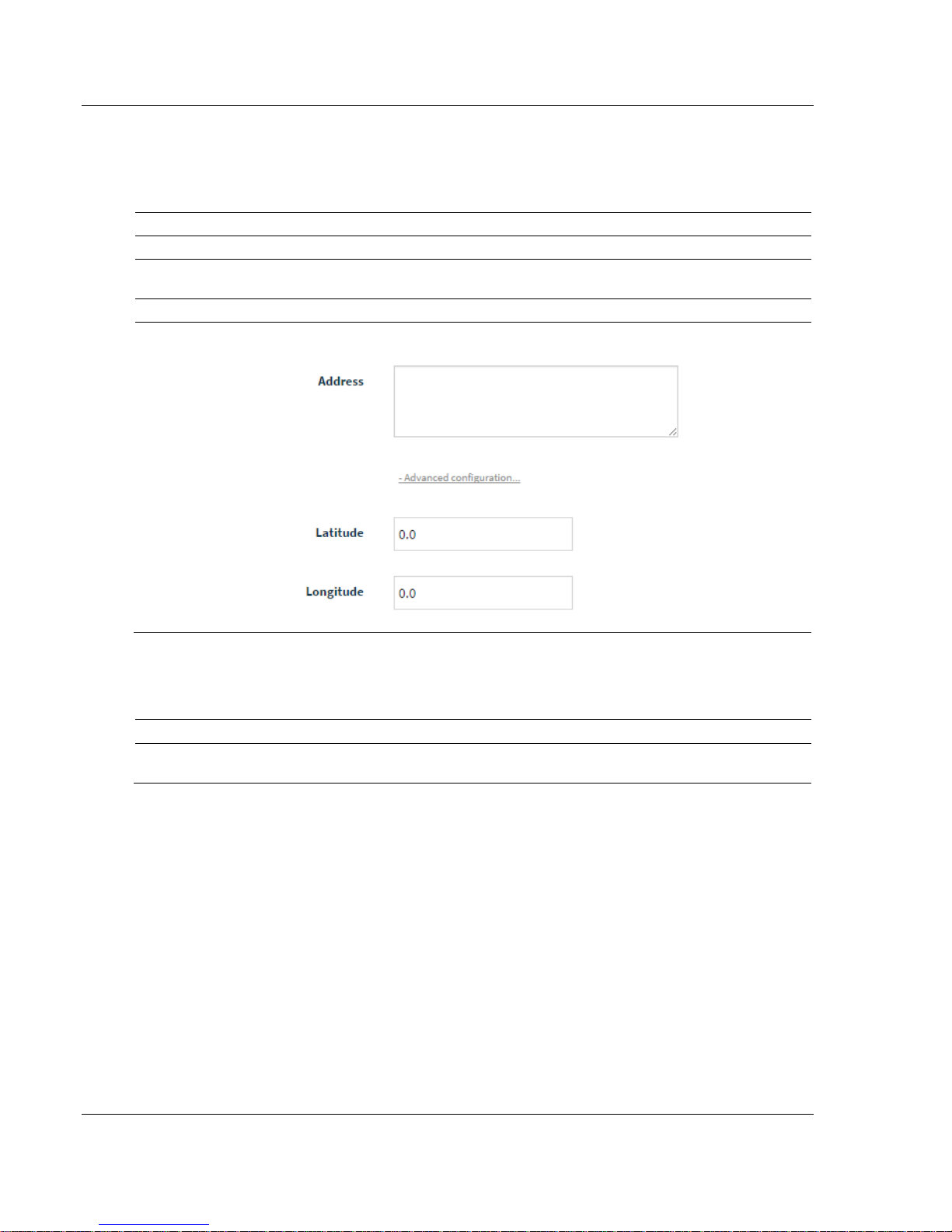
4.3 Setting Gateway Configuration Parameters
1 Click on the Gateway tab.
ProSoft Technology, Inc. Page 19 of 55
November 15, 2018
Page 20
Local Configuration using the PLX35-NB2 Configuration Webpage PLX35-NB2 ♦
Parameter
Description
Gateway Name
Enter a name for this gateway.
Description
Enter a description to describe the gateway. For example, Network Bridge -
Bakersfield.
Address
Enter the street address of the gateway (i.e., where the gateway resides)
Advanced
configuration (link)
This link allows you to provide GPS coordinates of the gateway's location. When
entered, the gateway location is visible on a map on the Overview tab.
Parameter
Description
IP
Enter the IP address of the gateway. This is a static IP address. The default IP
address is 192.168.0.250. (The netmask is always 255.255.255.0).
User Manual Network Bridge
2 Use the following tables to enter the appropriate parameters:
Gateway
Local Area Network
Page 20 of 55 ProSoft Technology, Inc.
November 15, 2018
Page 21

PLX35-NB2 ♦ Local Configuration using the PLX35-NB2 Configuration Webpage
DHCP Server
Use this parameter to enable or disable DHCP. The default is Disabled. If you want
to use a DHCP server to select an IP, select Enabled.
Selecting Enabled displays a number of additional DHCP-related parameters
DHCP Lease Time - Allows you to select lease times in hour, minutes, or seconds.
This is the amount of time an IP address remains available on a particular device
before releasing the IP address for use by another device.
DHCP Lease Units - Allows you to specify Hours and Minutes and works in
conjunction with DHCP Lease Time.
DHCP Pool Low - DHCP uses a pool of assigned addresses that are available to
requests. DHCP Pool Low allows you to set the last octet to the low end number of
the pool. (See example below)
DHCP Pool High - DHCP uses a pool of assigned addresses that are available for
use. DHCP Pool High allows you to specify the high-end last octet of the pool
For example:
This example specifies that the range of addresses that may be used is between
192.168.72.100 through 192.168.72.249.
NTP
This parameter specifies whether or not the Network Time Protocol (NTP) is
enabled or disabled. The default is Enabled. If Disabled, the following two
parameters are not present.
NTP Server
Set to 0.us.pool.ntp.org. If you wish to use a different NTP server, enter it here.
NTP Mode
Default is Client. You can change this to Client/Server mode.
Network Bridge User Manual
ProSoft Technology, Inc. Page 21 of 55
November 15, 2018
Page 22

Local Configuration using the PLX35-NB2 Configuration Webpage PLX35-NB2 ♦
Parameter
Description
DHCP Client
This is set to Enabled by default. If your administrator wants to assign a static IP, this
should be set to Disabled.
If Disabled, you must supply the following information:
IP - The IP address assigned to the WAN port.
Subnet - Enter the subnet address.
Gateway - Enter the gateway address for this subnet.
DNS 1 - Enter the Domain Name Server IP provided to your system.
DNS 2 - Enter the backup Domain Name Server IP provided to your system.
VLAN ID
If the gateway is part of a VLAN, enter the VLAN ID.
User Manual Network Bridge
Wide Area Network (WAN)
3 Click the Apply Changes button when complete.
4.4 Configuring Login Credentials
The gateway is shipped with the following login defaults:
User: admin
Password: password
The Access tab allows you to change the defaults.
1 Click on the Access tab to view the Access page.
This page allows you to set up the users that can manage and configure this
gateway. The Advanced Configuration link allows you to restrict access
based on user.
2 Enter a user name.
3 Enter a password.
Page 22 of 55 ProSoft Technology, Inc.
November 15, 2018
4 Confirm the password by retyping it.
Page 23

PLX35-NB2 ♦ Local Configuration using the PLX35-NB2 Configuration Webpage
Network Bridge User Manual
Advanced configuration
1 Click on the Advanced Configuration link.
2 Select the Web Protocol. Select HTTP or HTTPS.
3 Choose the port depending on what protocol is selected.
4 Click APPLY CHANGES when complete.
ProSoft Technology, Inc. Page 23 of 55
November 15, 2018
Page 24

Local Configuration using the PLX35-NB2 Configuration Webpage PLX35-NB2 ♦
User Manual Network Bridge
4.5 Viewing Gateway Log file Activity
1 Click on the ACTIVITY tab.
Options on this page include search, search filter options, and a Download
log file option.
2 Click on the DOWNLOAD LOG FILE button to download a .txt file to the
download folder of your PC or laptop.
Note: Some options that appear in the configuration UI may not be available during management
or configuration options within ProSoft Connect.
Page 24 of 55 ProSoft Technology, Inc.
November 15, 2018
Page 25

PLX35-NB2 ♦ Local Configuration using the PLX35-NB2 Configuration Webpage
Network Bridge User Manual
4.6 Importing a Configuration File
1 Select IMPORT CONFIGURATION from the setup icon located in the upper-right
corner of any configuration page.
2 Locate and select a configuration file to import and then click the Import
button.
4.7 Exporting a Configuration File
1 Select Export Configuration from the setup icon located in the upper-right
corner of any configuration page.
2 The gateway downloads a tar.gz file to your PC or laptop. Do not modify this
file.
ProSoft Technology, Inc. Page 25 of 55
November 15, 2018
Page 26

Local Configuration using the PLX35-NB2 Configuration Webpage PLX35-NB2 ♦
User Manual Network Bridge
4.8 Updating the Gateway's Firmware (NB2)
Note: ProSoft Connect can easily schedule updates to the latest firmware for multiple PLX35-NB2
gateways.
1 Click the SETUP icon in the top-right corner of the page and then click
CHANGE FIRMWARE.
This opens the Change firmware dialog.
2 Click the CHOOSE FILE button and locate the firmware file.
3 Select the file and click OPEN.
4 Click the CHANGE button to load the new firmware.
Page 26 of 55 ProSoft Technology, Inc.
November 15, 2018
Page 27

PLX35-NB2 ♦ Local Configuration using the PLX35-NB2 Configuration Webpage
Network Bridge User Manual
4.9 Rebooting the Gateway
1 Click the SETUP icon in the upper-right corner of the page and then click
REBOOT GATEWAY.
This opens the Reboot gateway dialog.
2 Click the REBOOT button when ready.
ProSoft Technology, Inc. Page 27 of 55
November 15, 2018
Page 28

PLX35-NB2 ♦
User Manual Network Bridge
Page 28 of 55 ProSoft Technology, Inc.
November 15, 2018
Page 29

PLX35-NB2 ♦ Cloud-based Management using ProSoft Connect
Network Bridge User Manual
5 Cloud-based Management using ProSoft
Connect
ProSoft Connect allows you to manage multiple gateways on the network
through a secure VLAN tunnel via a webpage. You can perform multiple tasks,
including activating, setting up VPN clients, perform configuration and
maintenance, and invite team members.
5.1 Login and Activate ProSoft Connect
Obtaining the Activation Key
ProSoft Connect requires that you activate the PLX35-NB2 the first time you use
it. You must obtain an activation key from the gateway.
1 Connect your gateway WAN port to a network that can reach the internet.
The MGMT LED will flash GREEN if the PLX35-NB2 can reach the internet
and is not yet activated.
2 Log in to the module from the LAN port as described in the section entitled
"Connecting to the PLX35-NB2 Webpage (page 17)". This takes you to the
Overview tab.
3 Under Device Details, click the ACTIVATE link to the right of the ProSoft
Connect label.
Note: If the gateway is already connected to a ProSoft Connect account, the link reads
“Deactivate”.
4 The gateway securely retrieves an alphanumeric activation key from ProSoft
Connect that is only valid for three (3) hours. Record this activation key.
Note: The module must be connected to the internet through the WAN port in order for the module
to retrieve an activation key.
5 Click the www.prosoft.io link, or open a new tab in your web browser, enter
www.prosoft.io in the address bar, and then press ENTER.
ProSoft Technology, Inc. Page 29 of 55
November 15, 2018
Page 30

Cloud-based Management using ProSoft Connect PLX35-NB2 ♦
User Manual Network Bridge
6 In the ProSoft Connect Login screen, enter your ProSoft Connect login email
and password and click LOGIN, or click SIGN UP NOW to create a new account.
Login credentials are not interchangeable between ProSoft Connect and the
local interface.
7 After you are logged in, you can take a tour of the features of ProSoft
Connect by clicking TAKE THE TOUR.
Page 30 of 55 ProSoft Technology, Inc.
November 15, 2018
Page 31

PLX35-NB2 ♦ Cloud-based Management using ProSoft Connect
Network Bridge User Manual
8 When ready, activate the PLX35-NB2 within the tour, or you can click on the
ACTIVATE A GATEWAY button at the top of the page. ProSoft Connect prompts
you for the activation key that you recorded earlier in these steps.
9 Enter the activation key you recorded earlier. Upon successful activation, the
PLX35-NB2 appears on the Gateways page.
ProSoft Technology, Inc. Page 31 of 55
November 15, 2018
Page 32

Cloud-based Management using ProSoft Connect PLX35-NB2 ♦
User Manual Network Bridge
5.2 Create a new VPN Client
ProSoft Connect uses your native Windows VPN client for secure remote access.
The first time you intend to establish a VPN connection, you must set up the
client and then connect to it. Initial VPN client configuration is only done once
and is described in the following steps. If you already have a ProSoft Connect
VPN Client established in your Network Connections folder, you do not need to
perform these steps.
Once your PLX35-NB2 is activated, the gateway is displayed on the Gateways
page. ProSoft Connect uses the OS native VPN client. The first time you attempt
to create a VPN tunnel, you’ll need to set up this VPN client to work with the
ProSoft Connect Server. This is a one-time setup and will not need to be
repeated for additional gateways.
Page 32 of 55 ProSoft Technology, Inc.
November 15, 2018
Page 33

PLX35-NB2 ♦ Cloud-based Management using ProSoft Connect
Network Bridge User Manual
1 Click on the CONNECT button. The system generates a unique secure one-
time use username.
2 Click the COPY TO CLIPBOARD button to save this username.
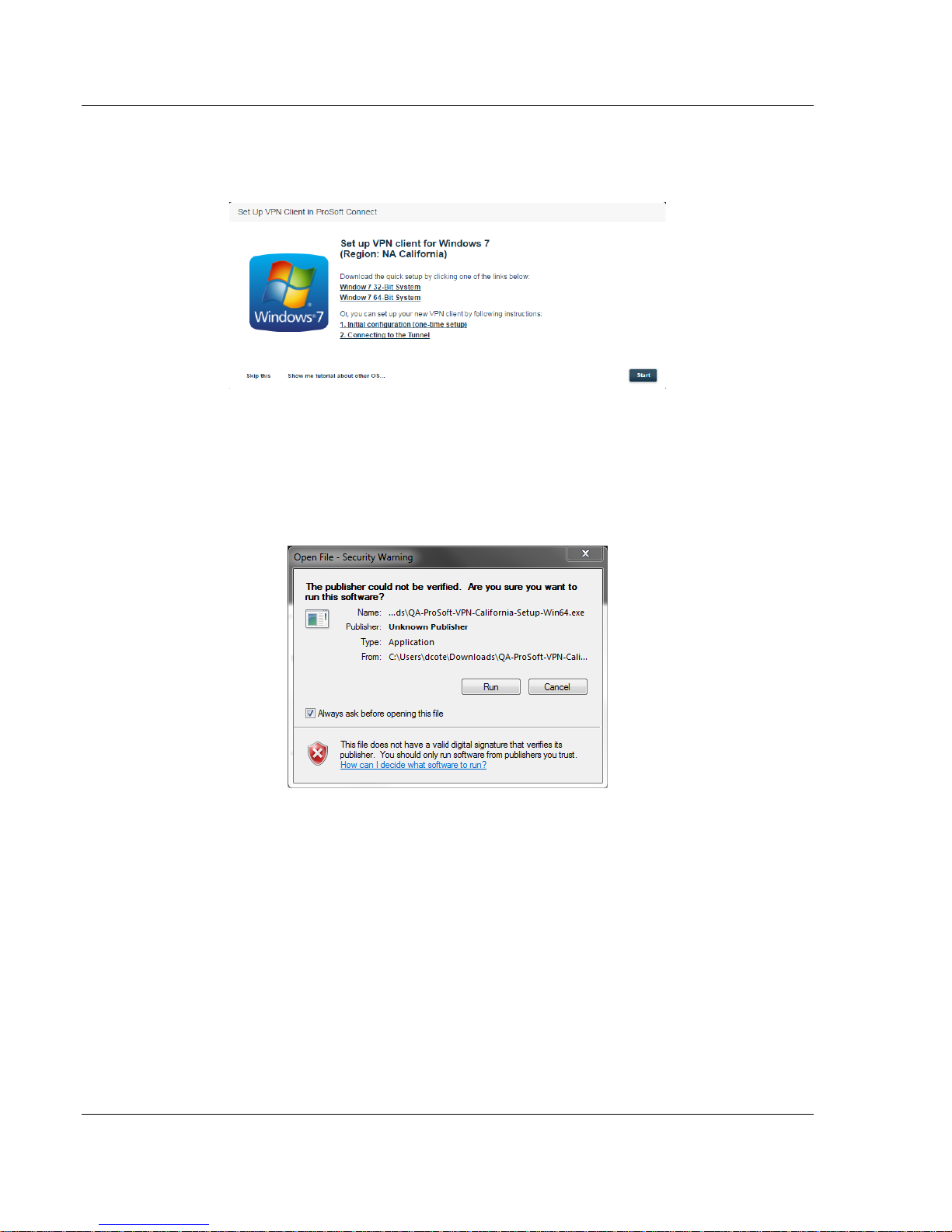
3 Click "SHOW ME HOW TO SETUP MY VPN CLIENT." This opens the VPN Client
Setup dialog.
ProSoft Technology, Inc. Page 33 of 55
November 15, 2018
Page 34
Cloud-based Management using ProSoft Connect PLX35-NB2 ♦
User Manual Network Bridge
4 Choose your platform by clicking on the appropriate platform icon. This
displays script download instructions. The script sets up your VPN client
automatically.
This dialog allows you to perform an automatic quick setup (requires
download of a setup script) or provides instructions on manually performing
the initial configuration. If you want to configure the VPN manually, click on
the INITIAL CONFIGURATION (ONE TIME SETUP) link.
If you want to run the quick setup script, click on the appropriate download
link. Once the setup script downloads, run the script to install it.
5 Click YES at the next prompt.
6 Click YES to accept the End User License Agreement.
7 At the next prompt, select ALL USERS or MY USE ONLY. This connection will be
placed in the Network Connections folder on your PC or Laptop. You can also
add a shortcut on the desktop. Click OK.
Page 34 of 55 ProSoft Technology, Inc.
November 15, 2018
Page 35

PLX35-NB2 ♦ Cloud-based Management using ProSoft Connect
Network Bridge User Manual
8 Once set up, you are prompted to enter your User name.
9 Paste the user name from your clipboard.
Note: If you have lost the key, simply disconnect and then connect again to retrieve a new key.
10 Click the CONNECT button to open the VPN tunnel.
The Disconnect button indicates that you have a VPN connection in progress.
ProSoft Technology, Inc. Page 35 of 55
November 15, 2018
Page 36

Cloud-based Management using ProSoft Connect PLX35-NB2 ♦
User Manual Network Bridge
5.3 Establish a VPN Connection
1 Access and login to ProSoft Connect.
2 Click the CONNECT button.
Page 36 of 55 ProSoft Technology, Inc.
November 15, 2018
Page 37

PLX35-NB2 ♦ Cloud-based Management using ProSoft Connect
Network Bridge User Manual
3 Copy the generated User name to the clipboard.
4 Navigate to your Network Connections folder and double-click on the
PROSOFT CONNECT VPN CLIENT. (See note below.)
ProSoft Technology, Inc. Page 37 of 55
November 15, 2018
Page 38

Cloud-based Management using ProSoft Connect PLX35-NB2 ♦
User Manual Network Bridge
5 Paste the clipboard contents into the User name field of the Connection
dialog.
6 Click the CONNECT button, this creates a VPN tunnel.
Note: You can get to the Network Connections folder by clicking on the Open Network and Sharing
Center icon to display connected (or non-connected items. Under Dial-up and VPN, double click on
ProSoft Connect.
Page 38 of 55 ProSoft Technology, Inc.
November 15, 2018
Page 39

PLX35-NB2 ♦ Cloud-based Management using ProSoft Connect
Network Bridge User Manual
5.3.1 Verifying the VPN Connection
The module on the Gateways page of ProSoft Connect provides a VPN indicator
as shown:
You can view the connection status by hovering over the VPN icon or by
hovering over the status at the top of the page. See the next section for more
details.
This indicator is grayed out if there is no connection established. However, you
can hover over this indicator to obtain more information about the connection.
This example shows that the gateway is connected to the cloud server and the
user is connected to the gateway.
If only one part of the tunnel connection is established, the indication may appear
as shown below:
ProSoft Technology, Inc. Page 39 of 55
November 15, 2018
Page 40

Cloud-based Management using ProSoft Connect PLX35-NB2 ♦
User Manual Network Bridge
This example shows that there is a connection between the gateway and the
cloud server. However, it shows the user as "Disconnected". In this case, ProSoft
Connect may be waiting for the user to provide a generated User name in order
to login to the gateway.
5.4 Using ProSoft Connect to Configure the PLX35-NB2
All configuration tasks may be performed using ProSoft Connect. That is, you do
not need to use the module's internal web server to configure the module or edit
existing configurations.
To access configuration parameters, click on the setup icon or click on the
module name.
This opens the gateway's configuration pages.
In addition to the normal features of ProSoft Connect, these configuration pages
are exclusive to the PLX35-NB2. All configuration fields are accessible via the
tabs located at the top of the page.
Page 40 of 55 ProSoft Technology, Inc.
November 15, 2018
Page 41

PLX35-NB2 ♦ Cloud-based Management using ProSoft Connect
Parameter
Description
Overview tab
This tab provides performance information as well as general overall
device health and identification information. See "Viewing the
Overview Page (page 19)" for additional information.
Gateway tab
This tab provides gateway identification information as well as
specifics about LAN settings and WAN settings. See "Setting Gateway
Configuration Parameters (page 19)"
Network Bridge User Manual
The configuration parameters are the same as those described under "Local
Configuration using the Gateway's Configuration Webpage (page 16)".
ProSoft Technology, Inc. Page 41 of 55
November 15, 2018
Page 42

Cloud-based Management using ProSoft Connect PLX35-NB2 ♦
Access tab
This tab allows you to set a user and password in place of the default.
See "Configuring User Access (page 22)".
Activity tab
This tab allows you to view system activity. See "Viewing Gateway
Logfile Activity (NB2) (page 24)"
User Manual Network Bridge
Page 42 of 55 ProSoft Technology, Inc.
November 15, 2018
Page 43

PLX35-NB2 ♦ Cloud-based Management using ProSoft Connect
Network Bridge User Manual
5.5 Adding Team Members
Within ProSoft Connect, you can invite team members to your account. This
allows others to securely access the remote site and perform maintenance and
configuration functions on the gateway once invites are accepted.
1 Click on the Team icon.
2 Click on the INVITE TEAM MEMBERS button located in the upper-right hand
corner of the page.
The Invite dialog opens.
ProSoft Technology, Inc. Page 43 of 55
November 15, 2018
Page 44

Cloud-based Management using ProSoft Connect PLX35-NB2 ♦
User Manual Network Bridge
3 Enter the email address of the person you want to invite. You can enter
multiple team members.
Note: An email address can only be associated with one ProSoft Connect account at a time.
4 Modify the Message dialog to send a unique message to the invitees.
5 When you are done, click the SEND INVITATIONS button. You should receive
an “invitation sent successfully” message if the email address was valid. You
can edit a member’s access rights once the invite is sent.
5.5.1 Editing Team Member Access
As an administrator, you can control the type of access rights assigned to your
team members. When a team member accepts an invitation, a card appears on
the Team page of ProSoft Connect.
1 Click on the EDIT ACCESS button located on the card.
This opens the access dialog for the new team member. Initially, access
defaults to "Connect only" which means that that user is allowed to create a
tunnel, but is not allowed to configure a gateway.
2 Change this user's access rights by clicking on any of the first 3 access
selections and then click the SAVE ACCESS button.
Page 44 of 55 ProSoft Technology, Inc.
November 15, 2018
Page 45

PLX35-NB2 ♦ Cloud-based Management using ProSoft Connect
Network Bridge User Manual
5.6 Changing Firmware
You can schedule a firmware change for multiple gateways or a single gateway
through ProSoft Connect. The are two ways to start the firmware change
process:
Click the firmware CHANGE hyperlink in the Device Details block
Select CHANGE FIRMWARE from the setup icon in the top-right corner of every
configuration page.
Use one of the above methods and perform the following steps.
1 Click on the Change link to open the Firmware Upgrade dialog.
This dialog list the most recent firmware versions and details about this version.
2 Select the version that you want to install by clicking the correct version's
radio button.
ProSoft Technology, Inc. Page 45 of 55
November 15, 2018
Page 46

Cloud-based Management using ProSoft Connect PLX35-NB2 ♦
User Manual Network Bridge
At this point, you have two options:
Change Now - Allows you select additional gateways for upgrade and then
immediately performs the upgrade.
Schedule for Later - Allows you to select additional gateways for upgrade
and then allows you to schedule a data and time for the upgrade to occur.
Change Now
1 With the correct firmware version selected, click the CHANGE NOW button.
You are prompted as to whether or not you want to upgrade other gateways.
2 Choose any available gateways that you want to upgrade, if applicable.
3 Click the APPLY ONLY TO THIS GATEWAY button if you have do not need to
upgrade additional gateways or click the APPLY TO THIS GATEWAY AND
SELECTED button to upgrade firmware on the current gateway and any
selected gateways.
The firmware upgrade starts immediately.
Page 46 of 55 ProSoft Technology, Inc.
November 15, 2018
Page 47

PLX35-NB2 ♦ Cloud-based Management using ProSoft Connect
Network Bridge User Manual
Schedule for Later
1 With the correct firmware version selected, click the SCHEDULE FOR LATER
button. You are prompted as to whether or not you want to schedule
upgrades for other gateways.
2 If you don't want to schedule upgrades for other gateways, click the
APPLY ONLY TO THIS GATEWAY button to schedule the upgrade.
ProSoft Technology, Inc. Page 47 of 55
November 15, 2018
Page 48

Cloud-based Management using ProSoft Connect PLX35-NB2 ♦
User Manual Network Bridge
3 Schedule the date and time for the firmware change to occur.
4 Click the SCHEDULE button.
5 If you want to schedule changes for other gateways, use the APPLY TO
THIS GATEWAY AND SELECTED button and follow the same procedure.
Note: You can also access the Change firmware function using the setup options cogwheel drop-
down located in the upper-right portion of any configuration page.
Page 48 of 55 ProSoft Technology, Inc.
November 15, 2018
Page 49

PLX35-NB2 ♦ Ethernet Cable Specifications
Crossover cable
Straight- through cable
RJ-45 PIN
RJ-45 PIN
1 Rx+
3 Tx+
2 Rx-
6 Tx-
3 Tx+
1 Rx+
6 Tx-
2 Rx-
RJ-45 PIN
RJ-45 PIN
1 Rx+
1 Tx+
2 Rx-
2 Tx-
3 Tx+
3 Rx+
6 Tx-
6 Rx-
Network Bridge User Manual
6 Ethernet Cable Specifications
ProSoft recommends using using a category 5 (or better) Ethernet cable with the
PLX35-NB2. A category 5 cable has four twisted pairs of wire that are colorcoded and cannot be swapped. The gateway only uses two of the four pairs
when running at 10 MBit or 100 MBit speeds.
The Ethernet port on the gateway automatically detects the network speed and
cable type and use the appropriate pins to send and receive Ethernet signals.
Use either a standard Ethernet straight-through cable or a crossover cable when
connecting the gateway to an Ethernet hub, a 10/100/1000 Base-T Ethernet
switch, or directly to a PC.
6.1 Ethernet Cable Configuration
Note: The standard connector view shown is color-coded for a straight-through cable.
ProSoft Technology, Inc. Page 49 of 55
November 15, 2018
Page 50

PLX35-NB2 ♦
User Manual Network Bridge
Page 50 of 55 ProSoft Technology, Inc.
November 15, 2018
Page 51

PLX35-NB2 ♦ Support, Service & Warranty
Network Bridge User Manual
7 Support, Service & Warranty
7.1 Contacting Technical Support
With ProSoft Connect, you may click on the Support link at any time to initiate a
chat with Support about issues in ProSoft Connect, or gateways managed by
ProSoft Connect.
ProSoft Technology, Inc. is committed to providing the most efficient and
effective support possible. Before calling, please gather the following information
to assist in expediting this process:
1 Product Version Number
2 System architecture
3 Network details
If the issue is hardware related, we will also need information regarding:
1 Module configuration and associated ladder files, if any
2 Module operation and any unusual behavior
3 Configuration/Debug status information
4 LED patterns
5 Details about the serial, Ethernet or Fieldbus devices interfaced to the
module, if any.
Note: For technical support calls within the United States, ProSoft’s 24/7 after-hours phone support
is available for urgent plant-down issues. Detailed contact information for all our worldwide
locations is available on the following page.
ProSoft Technology, Inc. Page 51 of 55
November 15, 2018
Page 52

Support, Service & Warranty PLX35-NB2 ♦
Asia Pacific
Europe / Middle East / Africa
Regional Office
Phone: +603.7724.2080
asiapc@prosoft-technology.com
Languages spoken: Bahasa, Chinese, English,
Japanese, Korean
REGIONAL TECH SUPPORT
support.ap@prosoft-technology.com
North Asia (China, Hong Kong)
Phone: +86.21.5187.7337
china@prosoft-technology.com
Languages spoken: Chinese, English
REGIONAL TECH SUPPORT
support.ap@prosoft-technology.com
Southwest Asia (India, Pakistan)
Phone: +91.98.1063.7873
india@prosoft-technology.com
Languages spoken: English, Hindi, Urdu
Australasia (Australia, New Zealand)
Phone: +603.7724.2080
pacific@prosoft-technology.com
Language spoken: English
Southeast Asia (Singapore, Indonesia,
Philippines)
Phone: +603.7724.2080
seasia@prosoft-technology.com
Languages spoken: English, Bahasa, Tamil
Northeast & Southeast Asia
(Japan, Taiwan, Thailand, Vietnam, Malaysia)
Phone: +603.7724.2080
neasia@prosoft-technology.com
Languages spoken: English, Chinese, Japanese
Korea
Phone: +603.7724.2080
korea@prosoft-technology.com
Languages spoken: English, Korean
Regional Office
Phone: +33.(0)5.34.36.87.20
europe@prosoft-technology.com
Languages spoken: French, English
REGIONAL TECH SUPPORT
support.emea@prosoft-technology.com
Middle East & Africa
Phone: +971.4.214.6911
mea@prosoft-technology.com
Languages spoken: Hindi, English
REGIONAL TECH SUPPORT
support.emea@prosoft-technology.com
North Western Europe (UK, IE, IS, DK, NO, SE)
Phone: +44.(0)7415.864.902
nweurope@prosoft-technology.com
Language spoken: English
Central & Eastern Europe, Finland
Phone: +48.22.250.2546
centraleurope@prosoft-technology.com
Languages spoken: Polish, English, Russia & CIS
Phone: +7.499.704.53.46
russia@prosoft-technology.com
Languages spoken: Russian, English
Austria, Germany, Switzerland
Phone: +33.(0)5.34.36.87.20
germany@prosoft-technology.com
Language spoken: English, German
BeNeLux, France, North Africa
Phone: +33(0)5.34.36.87.27
france@prosoft-technology.com
Languages spoken: French, English
Mediterranean Countries
Phone: +39.342.8651.595
italy@prosoft-technology.com
Languages spoken: Italian, English, Spanish
User Manual Network Bridge
Page 52 of 55 ProSoft Technology, Inc.
November 15, 2018
Page 53

PLX35-NB2 ♦ Support, Service & Warranty
Latin America
North America
Regional Office
Phone: +52.222.264.1814
support.la@prosoft-technology.com
Languages spoken: Spanish, English
REGIONAL TECH SUPPORT
support.la@prosoft-technology.com
Brazil
Phone: +55.11.5084.5178
brasil@prosoft-technology.com
Languages spoken: Portuguese, English
REGIONAL TECH SUPPORT
support.la@prosoft-technology.com
Mexico
Phone: +52.222.264.1814
mexico@prosoft-technology.com
Languages spoken: Spanish, English
REGIONAL TECH SUPPORT
support.la@prosoft-technology.com
Andean Countries, Central America &
Caribbean
Phone: +507.6427.48.38
andean@prosoft-technology.com
Languages spoken: Spanish, English
Southern Cone (Argentina, Bolivia, Chile,
Paraguay & Uruguay)
Phone: +54.911.4565.8119
scone@prosoft-technology.com
Languages spoken: Spanish, English
Regional Office
Phone: +1.661.716.5100
info@prosoft-technology.com
Languages spoken: English, Spanish
REGIONAL TECH SUPPORT
support@prosoft-technology.com
Network Bridge User Manual
7.2 Warranty Information
ProSoft Technology, Inc. Page 53 of 55
November 15, 2018
For complete details regarding ProSoft Technology’s TERMS & CONDITIONS
OF SALE, WARRANTY, SUPPORT, SERVICE AND RETURN MATERIAL
AUTHORIZATION INSTRUCTIONS, please see the documents at:
www.prosoft-technology.com/legal
Documentation is subject to change without notice.
Page 54

PLX35-NB2 ♦ Support, Service & Warranty
Network Bridge User Manual
ProSoft Technology, Inc. Page 54 of 55
November 15, 2018
Page 55

PLX35-NB2 ♦ Index Support, Service & Warranty
Network Bridge User Manual
U
Index
A
About the PLX35-NB2 Network Bridge • 7
Adding Team Members • 43
Agency Approvals and Certifications • 3
C
Cloud-based Management using ProSoft Connect • 29
Configuring User Access • 22, 42
Connecting to the PLX35-NB2 Web Page • 17, 29
Contacting Technical Support • 9, 51
Content Disclaimer • 2
Create a new VPN Client • 32
E
Editing Team Member Access • 44
Establish a VPN Connection • 36
Ethernet Cable Configuration • 49
Ethernet Cable Specifications • 49
Exporting a Configuring File • 25
Updating Firmware • 45
Updating the Gateway's Firmware (NB2) • 26
Using ProSoft Connect to Configure the PLX35-NB2 •
40
V
Verifying the VPN Connection • 39
Viewing Gateway Logfile Activity (NB2) • 24, 42
Viewing the Overview Page • 19, 41
W
Warranty Information • 53
Y
Your Feedback Please • 2
H
How to Contact Us • 2
I
Important Installation Instructions • 3
Installing the PLX35-NB2 • 13
J
Jumper Information • 9
L
LED Indicators • 14
Local Configuration using the Gateway's Configuration
Webpage • 17, 41
Login and Activate ProSoft Connect • 29
P
PLX35-NB2 Package Contents • 9
R
Rebooting the Gateway • 27
S
Setting Gateway Configuration Parameters • 19, 41
Specifications • 8
Start Here • 7
Support, Service & Warranty • 51
ProSoft Technology, Inc. Page 55 of 55
November 15, 2018
 Loading...