

Page 1
PLX3x Series
Ethernet and Serial Gateways
September 17, 2014
USER MANUAL
Page 2

Your Feedback Please
We always want you to feel that you made the right decision to use our products. If you have suggestions, comments,
compliments or complaints about our products, documentation, or support, please write or call us.
How to Contact Us
ProSoft Technology
5201 Truxtun Ave., 3rd Floor
Bakersfield, CA 93309
+1 (661) 716-5100
+1 (661) 716-5101 (Fax)
www.prosoft-technology.com
support@prosoft-technology.com
Copyright © 2014 ProSoft Technology, Inc., All rights reserved.
PLX3x Series Ethernet and Serial Gateways User Manual
September 17, 2014
ProSoft Technology ®, ProLinx®, inRAx ®, ProTalk ®, and RadioLinx ® are Registered Trademarks of ProSoft
Technology, Inc. All other brand or product names are or may be trademarks of, and are used to identify products
and services of, their respective owners.
ProSoft Technology® Product Documentation
In an effort to conserve paper, ProSoft Technology no longer includes printed manuals with our product shipments.
User Manuals, Datasheets, Sample Ladder Files, and Configuration Files are provided on the enclosed DVD in
Adobe® Acrobat Reader file format (.PDFs). These product documentation files may also be freely downloaded from
our web site: http://www.prosoft-technology.com/
Literature Content Disclaimer
This documentation is not intended as a substitute for and is not to be used for determining suitability or reliability of
these products for specific user applications. It is the duty of any such user or integrator to perform the appropriate
and complete risk analysis, evaluation and testing of the products with respect to the relevant specific application or
use thereof. Neither ProSoft Technology nor any of its affiliates or subsidiaries shall be responsible or liable for
misuse of the information contained herein. Information in this document including illustrations, specifications and
dimensions may contain technical inaccuracies or typographical errors. ProSoft Technology makes no warranty or
representation as to its accuracy and assumes no liability for and reserves the right to correct such inaccuracies or
errors at any time without notice. If you have any suggestions for improvements or amendments or have found errors
in this publication, please notify us.
No part of this document may be reproduced in any form or by any means, electronic or mechanical, including
photocopying, without express written permission of ProSoft Technology. All pertinent state, regional, and local safety
regulations must be observed when installing and using this product. For reasons of safety and to help ensure
compliance with documented system data, only the manufacturer should perform repairs to components. When
devices are used for applications with technical safety requirements, the relevant instructions must be followed.
Failure to use ProSoft Technology software or approved software with our hardware products may result in injury,
harm, or improper operating results. Failure to observe this information can result in injury or equipment damage.
© 2014 ProSoft Technology. All rights reserved.
Page 3

CE Mark
UL/cUL Class I Div II
ATEX Zone 2
CB Safety
RoHS
Important Installation Instructions
Power, Input, and Output (I/O) wiring must be in accordance with Class I, Division 2 wiring methods, Article 501-4 (b)
of the National Electrical Code, NFPA 70 for installation in the U.S., or as specified in Section 18-1J2 of the Canadian
Electrical Code for installations in Canada, and in accordance with the authority having jurisdiction. The following
warnings must be heeded:
This Equipment is Suitable For Use in Class I, Division 2, Groups A, B, C, D or Non-Hazardous Locations Only
WARNING – Explosion Hazard – Substitution of Any Components May Impair Suitability for Class I, Division 2
WARNING – Explosion Hazard – Do Not Disconnect Equipment Unless Power Has Been Switched Off Or The Area
is Known To Be Non-Hazardous
Agency Approvals and Certifications
Page 4

Page 5

PLX3x Series Contents
Ethernet and Serial Gateways User Manual
Contents
Your Feedback Please ........................................................................................................................ 2
How to Contact Us .............................................................................................................................. 2
ProSoft Technology® Product Documentation .................................................................................... 2
Literature Content Disclaimer ............................................................................................................. 2
Important Installation Instructions ....................................................................................................... 3
Agency Approvals and Certifications .................................................................................................. 3
1 Start Here 9
1.1 System Requirements ............................................................................................... 9
1.2 Package Contents ................................................................................................... 10
1.3 Mounting the Gateway on a DIN-rail ....................................................................... 11
1.4 Jumper Settings ...................................................................................................... 12
1.5 SD Card ................................................................................................................... 12
1.6 Connecting Power to the PLX3x Gateway .............................................................. 13
2 Configuring Your Gateway 15
2.1 Installing ProSoft Configuration Builder Software ................................................... 16
2.2 Using the Online Help ............................................................................................. 17
2.3 Setting Up the Project ............................................................................................. 17
2.4 Renaming PCB Objects .......................................................................................... 20
2.5 Configuring the Drivers ............................................................................................ 21
2.6 Using the CommonNet Data Map ........................................................................... 25
2.7 Configuring an IP Address ...................................................................................... 27
2.8 Downloading the Project to the Gateway ................................................................ 29
2.9 Printing a Configuration File .................................................................................... 31
3 Diagnostics and Troubleshooting 33
3.1 LED Indicators ......................................................................................................... 34
3.1.1 Main Gateway LEDs ................................................................................................ 34
3.1.2 Ethernet Port LEDs ................................................................................................. 35
3.1.3 Serial Port LEDs (for Gateways with Serial Ports) .................................................. 35
3.2 Using Diagnostics in ProSoft Configuration Builder ................................................ 36
3.2.1 Diagnostics Menu .................................................................................................... 38
3.2.2 Capturing a Diagnostic Session to a Log File ......................................................... 40
3.2.3 Using the Data Analyzer (Serial Protocols Only) .................................................... 41
3.3 Gateway Status Data in Upper Memory .................................................................. 43
3.3.1 General Gateway Status Data in Upper Memory .................................................... 43
3.3.2 Protocol-Specific Status Data in Upper Memory ..................................................... 43
4 Hardware Information 45
4.1 Hardware Specifications.......................................................................................... 46
4.1.1 Serial Port Specifications ........................................................................................ 47
4.2 Serial Port Cables (for Gateways with Serial Ports) ............................................... 48
ProSoft Technology, Inc. Page 5 of 218
September 17, 2014
Page 6

Contents PLX3x Series
User Manual Ethernet and Serial Gateways
4.2.1 RS-232 - Null Modem (DTE with Hardware Handshaking) .................................... 48
4.2.2 RS-232 - Null Modem (DTE without Hardware Handshaking) ............................... 49
4.2.3 RS-232 - DTE to DCE Modem Connection ............................................................ 49
4.2.4 RS-422 Interface Connections ................................................................................ 50
4.2.5 RS-485 Interface Connections ................................................................................ 50
5 EIP Protocol 51
5.1 EIP Functional Overview ........................................................................................ 52
5.1.1 EtherNet/IP™ Client ............................................................................................... 53
5.2 EIP Configuration .................................................................................................... 54
5.2.1 EIP Class 3 Server Connection .............................................................................. 54
5.2.2 EIP Class 1 Connection .......................................................................................... 56
5.2.3 EIP Class 3 Client/UClient [x] Connection .............................................................. 58
5.3 EIP Diagnostics....................................................................................................... 70
5.3.1 PCB Diagnostics Menu ........................................................................................... 70
5.3.2 EIP Status Data in Upper Memory.......................................................................... 70
5.3.3 EIP Error Codes ...................................................................................................... 73
5.4 EIP Reference......................................................................................................... 77
5.4.1 SLC and MicroLogix Specifics ................................................................................ 77
5.4.2 PLC5 Processor Specifics ...................................................................................... 81
5.4.3 ControlLogix and CompactLogix Processor Specifics ............................................ 85
5.4.4 EIP Command Entry Form ...................................................................................... 92
6 MBTCP Protocol 93
6.1 MBTCP Functional Overview .................................................................................. 94
6.1.1 General Specifications - Modbus TCP/IP ............................................................... 94
6.1.2 Internal Database ................................................................................................... 95
6.2 MBTCP Configuration ............................................................................................. 98
6.2.1 MBTCP Servers ...................................................................................................... 98
6.2.2 MBTCP Client[x] ................................................................................................... 100
6.2.3 MBTCP Client[x] Commands ................................................................................ 102
6.3 MBTCP Diagnostics .............................................................................................. 105
6.3.1 PCB Diagnostics ................................................................................................... 105
6.3.2 MBTCP Status Data in Upper Memory ................................................................. 105
6.3.3 MBTCP Error Codes ............................................................................................. 108
6.4 MBTCP Reference ................................................................................................ 109
6.4.1 Modbus Protocol Specification ............................................................................. 109
7 MBS Protocol 121
7.1 MBS Functional Overview .................................................................................... 122
7.1.1 Modbus Serial Specifications ................................................................................ 122
7.1.2 Modbus Master/Slave Port Specifications ............................................................ 123
7.1.3 Gateway Internal Database .................................................................................. 124
7.2 MBS Configuration ................................................................................................ 125
7.2.1 MBS Port [x] .......................................................................................................... 125
7.2.2 MBS Port [x] Commands ...................................................................................... 129
7.3 MBS Diagnostics .................................................................................................. 132
7.3.1 PCB Diagnostics ................................................................................................... 132
7.3.2 MBS Status Data in Upper Memory ..................................................................... 132
7.3.3 Error/Status Codes ............................................................................................... 138
Page 6 of 218 ProSoft Technology, Inc.
September 17, 2014
Page 7

PLX3x Series Contents
Ethernet and Serial Gateways User Manual
7.4 MBS Reference ..................................................................................................... 139
7.4.1 Modbus Protocol Specification .............................................................................. 139
8 ASCII Protocol 151
8.1 ASCII Functional Overview ................................................................................... 152
8.1.1 General Specifications .......................................................................................... 152
8.1.2 Data Flow .............................................................................................................. 153
8.1.3 Modes of Operation ............................................................................................... 156
8.2 ASCII Configuration ............................................................................................... 161
8.2.1 ASCII Port [x] ......................................................................................................... 161
8.3 ASCII Diagnostics ................................................................................................. 163
8.3.1 PCB Diagnostics ................................................................................................... 163
8.3.2 ASCII Status Data in Upper Memory .................................................................... 163
9 SIE Protocol 165
9.1 SIE Functional Overview ....................................................................................... 166
9.1.1 General Specifications .......................................................................................... 166
9.1.2 Gateway Internal Database ................................................................................... 166
9.2 SIE Configuration .................................................................................................. 167
9.2.1 SIE Client x ............................................................................................................ 167
9.2.2 SIE Client x Commands ........................................................................................ 167
9.3 SIE Diagnostics ..................................................................................................... 181
9.3.1 Client Command Errors ......................................................................................... 181
9.3.2 SIE Error Codes .................................................................................................... 182
9.4 SIE Reference ....................................................................................................... 185
9.4.1 Maximum Register Counts .................................................................................... 185
10 PND Protocol 193
10.1 PND Functional Overview ..................................................................................... 194
10.2 PND Configuration ................................................................................................ 194
10.3 Step 7 Configuration .............................................................................................. 198
10.3.1 Monitoring Data in Step 7 ...................................................................................... 209
10.3.2 Creating a Variable Table to Display Floating Point Input Values ........................ 211
10.4 PND Diagnostics ................................................................................................... 213
10.4.1 Configuration Error Codes..................................................................................... 213
11 Support, Service and Warranty 215
11.1 Contacting Technical Support ............................................................................... 215
11.2 Warranty Information ............................................................................................. 216
Index 217
ProSoft Technology, Inc. Page 7 of 218
September 17, 2014
Page 8

Contents PLX3x Series
User Manual Ethernet and Serial Gateways
Page 8 of 218 ProSoft Technology, Inc.
September 17, 2014
Page 9

PLX3x Series Start Here
Ethernet and Serial Gateways User Manual
1 Start Here
In This Chapter
System Requirements ........................................................................ 9
Package Contents ............................................................................ 10
Mounting the Gateway on a DIN-rail ................................................. 11
Jumper Settings ................................................................................ 12
SD Card ............................................................................................ 12
Connecting Power to the PLX3x Gateway ........................................ 13
1.1 System Requirements
The ProSoft Configuration Builder configuration software for the gateway
requires the following minimum hardware and software components:
Pentium® II 450 MHz minimum. Pentium III 733 MHz (or better)
recommended
128 Mbytes of RAM minimum, 256 Mbytes of RAM recommended
100 Mbytes of free hard disk space (or more based on application
requirements)
256-color VGA graphics adapter, 800 x 600 minimum resolution (True Color
1024 768 recommended)
DVD drive
Supported operating systems:
Microsoft Windows 7 (32 bit)
Microsoft Windows XP Professional with Service Pack 1 or 2
ProSoft Technology, Inc. Page 9 of 218
September 17, 2014
Page 10

Start Here PLX3x Series
Qty.
Part Name
Part Number
Part Description
1
Ethernet cable
RL-CBL025
5’ straight-through cable
1
Mini screwdriver
HRD250
Tool for wiring and securing the power connector
1
Power connector
J180
PLX3x gateway power connector
1
ProSoft Solutions
DVD
DVD-001
Contains sample programs, utilities,
documentation and videos for the gateway
Qty.
Part Name
Part Number
Part Description
1
Ethernet cable
RL-CBL025
5’ straight-through cable
1
DB9 to Screw
Terminal Adaptor
1454-9F
DB9 to screw terminal adapter
1
RJ45-DB9M Serial
Adapter Cable
CABLE14
RJ45 to DB9 male serial adapter cable
1
Power Connector
J180
PLX3x gateway power connector
1
Mini screwdriver
HRD250
Tool for wiring and securing the power connector
1
ProSoft Solutions
DVD
DVD-001
Contains sample programs, utilities,
documentation and videos for the gateway
Qty.
Part Name
Part Number
Part Description
1
Ethernet cable
RL-CBL025
5’ straight-through cable
4
DB9 to Screw
Terminal Adaptor
1454-9F
DB9 to screw terminal adapter
4
RJ45-DB9M Serial
Adapter Cable
CABLE14
RJ45 to DB9 male serial adapter cable
1
Power Connector
J180
PLX3x gateway power connector
1
Mini screwdriver
HRD250
Tool for wiring and securing the power connector
1
ProSoft Solutions
DVD
DVD-001
Contains sample programs, utilities,
documentation and videos for the gateway
User Manual Ethernet and Serial Gateways
1.2 Package Contents
The following components are included with your gateway, and are all required
for installation and configuration. The quantity of cables provided depends on the
specific protocol combination being used.
Important: Before beginning the installation, please verify that all of the following items are
present.
Gateway with Ethernet Port
Gateway with Two Ethernet Ports
Gateway with Ethernet Port and Single Serial Port
Gateway with Ethernet Port and Four Serial Ports
Page 10 of 218 ProSoft Technology, Inc.
September 17, 2014
Page 11
PLX3x Series Start Here
Ethernet and Serial Gateways User Manual
1.3 Mounting the Gateway on a DIN-rail
ProSoft Technology, Inc. Page 11 of 218
September 17, 2014
Page 12

Start Here PLX3x Series
User Manual Ethernet and Serial Gateways
1.4 Jumper Settings
There are three sets of jumper settings located on the back of the module.
MODE 1 - Development Mode Jumper: This is the top jumper, used for
firmware updates only. The two pins should NOT be jumpered during
normal operation.
MODE 2 – Default IP Jumper: This is the middle jumper. The default IP
address of the ProLinx gateway is 192.168.0.250. Set this jumper to put
the gateway's IP address back to the default.
MODE 3 - Reserved: This is the bottom jumper, reserved for
internal ProSoft Technology use only. The firmware will not run when
these pins are shorted.
1.5 SD Card
PLX3x products can be ordered with an optional SD card (Part Number SDI-1G).
In the event of a disaster, the SD card can be moved from one module to the
next and resume operation. Below is a list of how the module will act - with and
without an SD card.
Without an SD Card
Configuration data is downloaded to the internal memory of the module.
If a blank SD Card is inserted in to the module after the module has been
configured, the configuration data will not be transferred to the SD card.
The configuration data would need to be downloaded to the module while
the SD card is in place.
With an SD Card
Configuration data is downloaded to the SD Card
The configuration data is not transferred from the SD card to the internal
memory of the module. If the SD card is removed and power is cycled to
the module, the module will load the configuration data from the module’s
memory. If there is no configuration data in the module’s memory, it will
be restored to factory default.
Page 12 of 218 ProSoft Technology, Inc.
September 17, 2014
Page 13
PLX3x Series Start Here
Ethernet and Serial Gateways User Manual
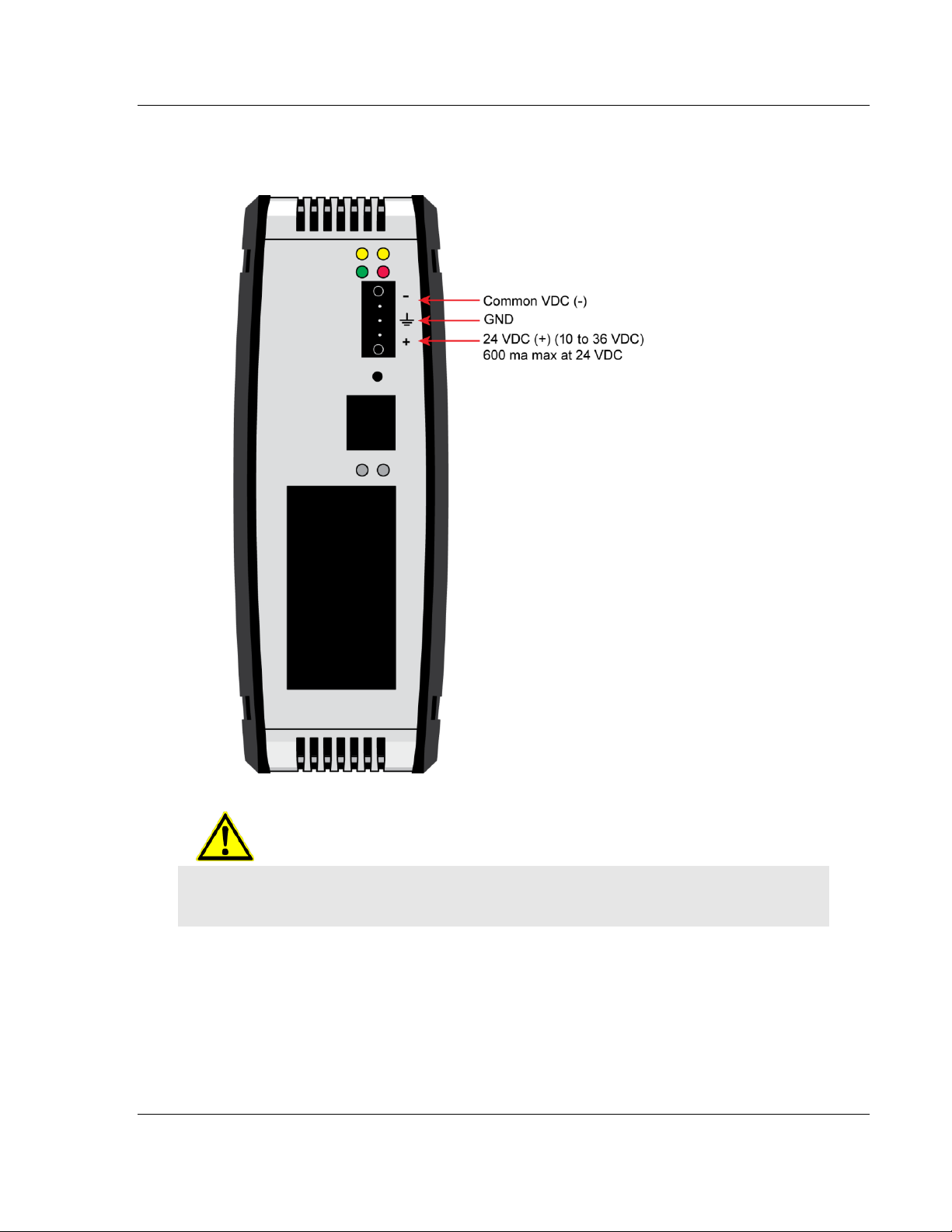
1.6 Connecting Power to the PLX3x Gateway
WARNING: Ensure that polarity is not reversed when applying power to the gateway. This will
cause damage to the gateway’s power supply.
ProSoft Technology, Inc. Page 13 of 218
September 17, 2014
Page 14

PLX3x Series
User Manual Ethernet and Serial Gateways
Page 14 of 218 ProSoft Technology, Inc.
September 17, 2014
Page 15

PLX3x Series Configuring Your Gateway
Ethernet and Serial Gateways User Manual
2 Configuring Your Gateway
In This Chapter
Installing ProSoft Configuration Builder Software ............................. 16
Using the Online Help ....................................................................... 17
Setting Up the Project ....................................................................... 17
Renaming PCB Objects .................................................................... 20
Configuring the Drivers ..................................................................... 21
Using the CommonNet Data Map ..................................................... 25
Configuring an IP Addres .................................................................. 27
Downloading the Project to the Gateway .......................................... 29
Printing a Configuration FIle ............................................................. 31
ProSoft Configuration Builder (PCB) is a convenient and powerful software tool
for managing your gateway configuration. Use PCB to configure a new project, or
to transfer an existing project to a new device. You can also to use PCB to
retrieve a configuration from a working gateway by uploading the configuration
from the gateway.
ProSoft Technology, Inc. Page 15 of 218
September 17, 2014
Page 16

Configuring Your Gateway PLX3x Series
User Manual Ethernet and Serial Gateways
2.1 Installing ProSoft Configuration Builder Software
You must install the ProSoft Configuration Builder (PCB) software to configure
the gateway. You can always get the newest version of ProSoft Configuration
Builder from the ProSoft Technology website.
To install ProSoft Configuration Builder from the ProSoft Technology website
1 Open your web browser and navigate to http://www.prosoft-
technology.com/pcb
2 Click the link at the Current Release Version section to download the latest
version of ProSoft Configuration Builder.
3 Choose SAVE or SAVE FILE when prompted.
4 Save the file to your Windows Desktop, so that you can find it easily when
you have finished downloading.
5 When the download is complete, locate and open the file, and then follow the
instructions on your screen to install the program.
If you do not have access to the Internet, you can install ProSoft Configuration
Builder from the ProSoft Solutions DVD, included in the package with your
gateway.
To Install ProSoft Configuration Builder from the DVD
1 Insert the ProSoft Solutions DVD into the DVD drive of your PC. Wait for the
DVD menu to appear.
2 On the startup screen, navigate to your product by selecting the proper
PLATFORM and PRODUCT.
3 Select PROSOFT CONFIGURAITON BUILDER. Follow the instructions on
your screen to install the software on your PC.
Page 16 of 218 ProSoft Technology, Inc.
September 17, 2014
Page 17
PLX3x Series Configuring Your Gateway
Ethernet and Serial Gateways User Manual
2.2 Using the Online Help
Most of the information needed to help you use ProSoft Configuration Builder is
provided in a Help System that is always available whenever you are running
ProSoft Configuration Builder. The Help System does not require an Internet
connection.
To view the help pages, start ProSoft Configuration Builder, open the HELP
menu, and then choose CONTENTS.
2.3 Setting Up the Project
To begin, start ProSoft Configuration Builder (PCB). If you have used other
Windows configuration tools before, you will find the screen layout familiar.
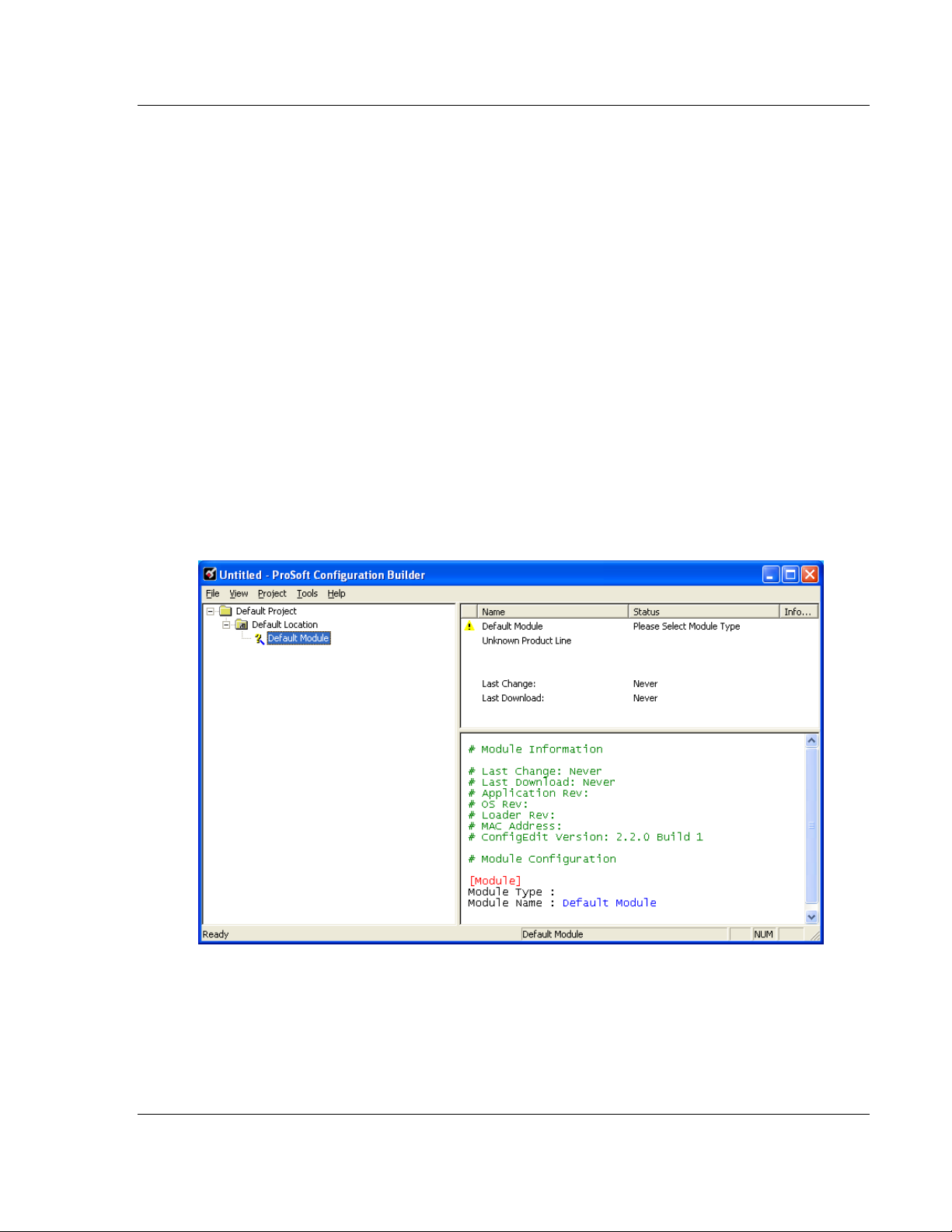
ProSoft Configuration Builder’s (PCB's) window consists of a tree view on the
left, and an information pane on the upper right side, and a configuration pane on
the lower right side of the window. When you first start PCB, the tree view
consists of folders for Default Project and Default Location, with a Default
Gateway in the Default Location folder. The following screen shows the PCB
window with a new project.
ProSoft Technology, Inc. Page 17 of 218
September 17, 2014
Page 18
Configuring Your Gateway PLX3x Series
User Manual Ethernet and Serial Gateways
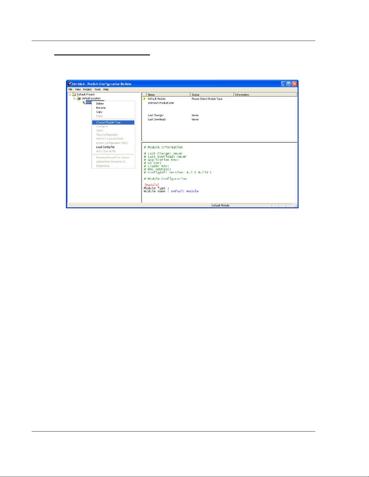
To add the gateway to the project
1 Use the mouse to select DEFAULT MODULE in the tree view, and then click
the right mouse button to open a shortcut menu.
Page 18 of 218 ProSoft Technology, Inc.
September 17, 2014
Page 19
PLX3x Series Configuring Your Gateway
Ethernet and Serial Gateways User Manual
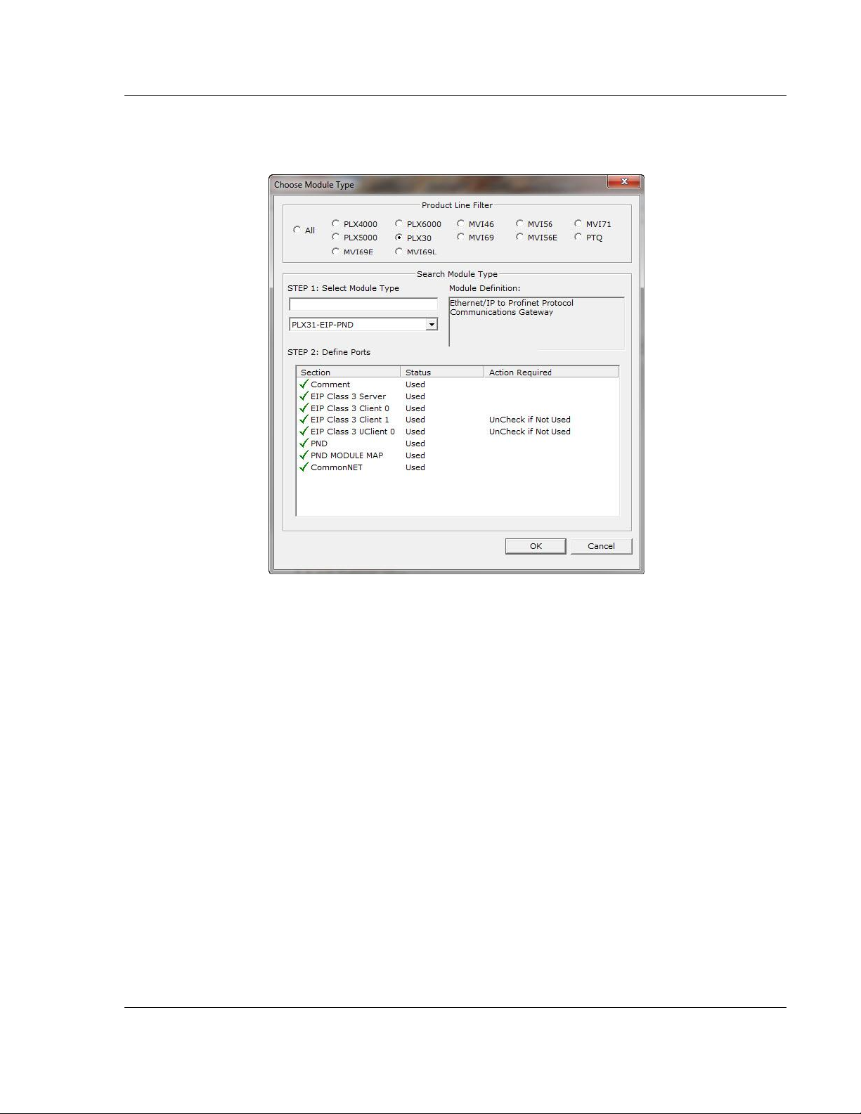
2 On the shortcut menu, select CHOOSE MODULE TYPE. This action opens
the Choose Module Type dialog box.
3 In the Product Line Filter area of the dialog box, select the PLX30 radio
button.
4 In the STEP 1: Select Module Type drop-down list, select the model number
that matches your gateway, and then click OK to save your settings and
return to the PCB Main window.
ProSoft Technology, Inc. Page 19 of 218
September 17, 2014
Page 20
Configuring Your Gateway PLX3x Series
User Manual Ethernet and Serial Gateways
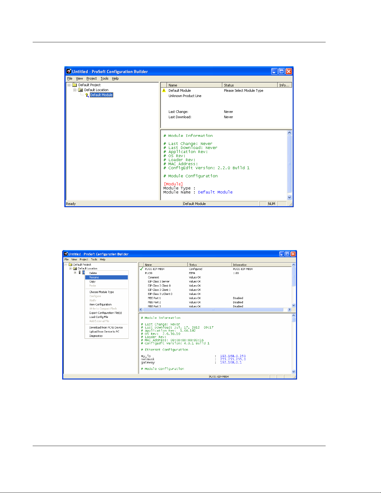
2.4 Renaming PCB Objects
The Default Project and Default Location folders may be renamed in the tree
view. Select the object, and then click the right mouse button to open a shortcut
menu. From the shortcut menu, choose RENAME.
1 Type the name to assign to the object.
2 Click away from the object to save the new name.
Page 20 of 218 ProSoft Technology, Inc.
September 17, 2014
Page 21
PLX3x Series Configuring Your Gateway
Ethernet and Serial Gateways User Manual
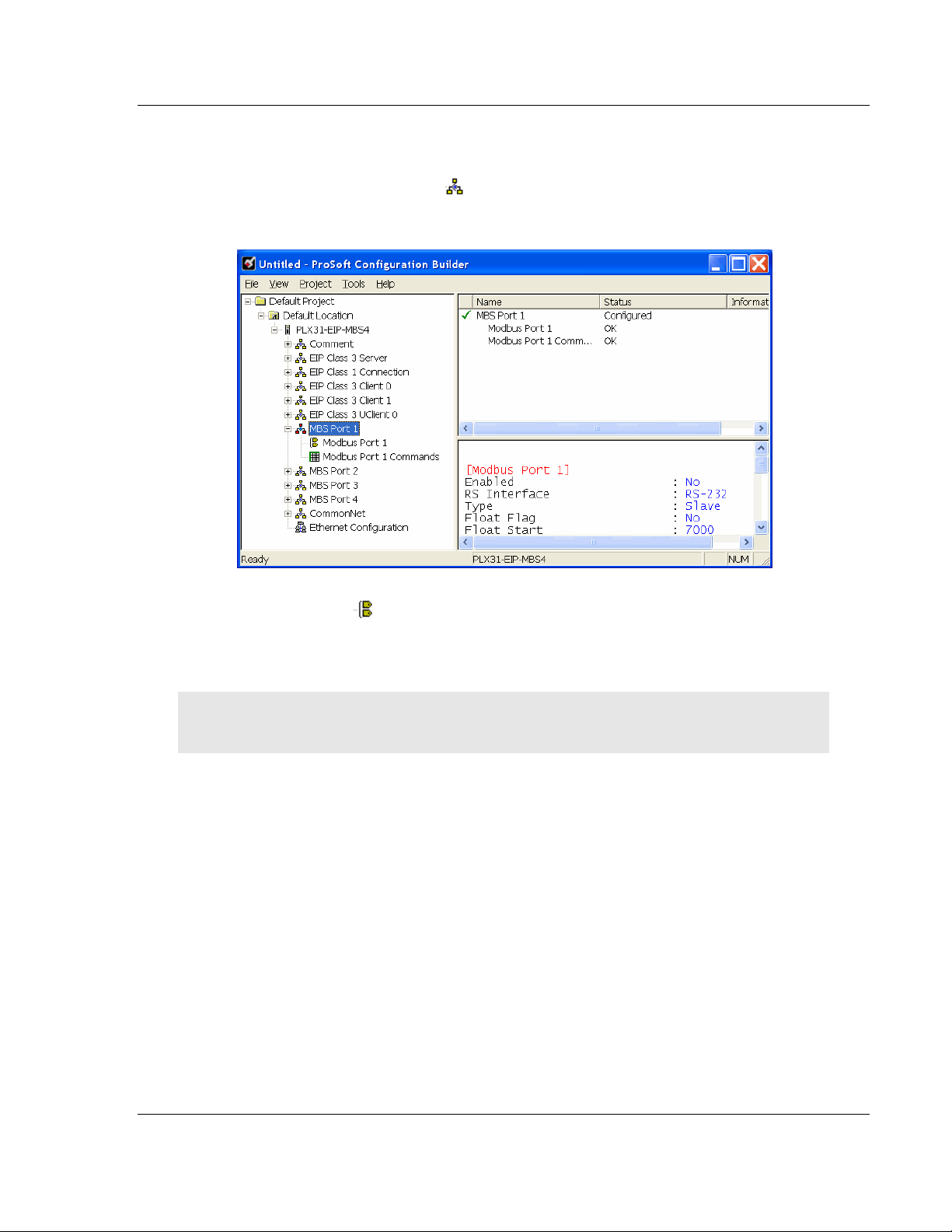
2.5 Configuring the Drivers
1 Click the [+] sign next to the Gateway icon to expand gateway information.
2 Click the [+] sign next to any icon to view gateway information and
configuration options.
3 Double-click any icon to open an Edit dialog box.
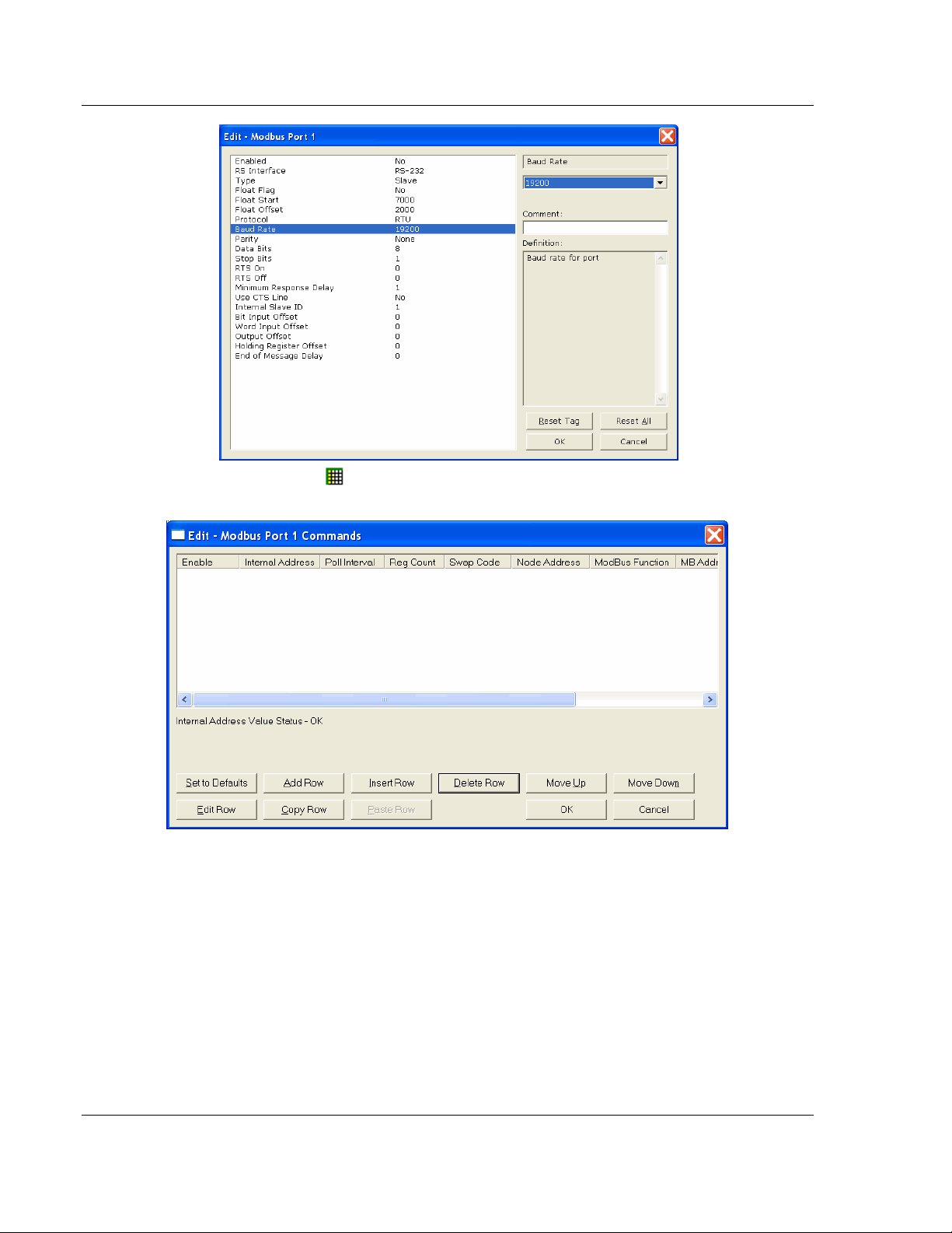
4 To edit a parameter, select the parameter name in the left hand pane, then
edit its corresponding field in the right hand pane.
Note: Depending on the parameter, the editable field will accept typed input in the form of text or a
valid numerical value, or it will have a dropdown list with options to choose from.
ProSoft Technology, Inc. Page 21 of 218
September 17, 2014
Page 22
Configuring Your Gateway PLX3x Series
User Manual Ethernet and Serial Gateways
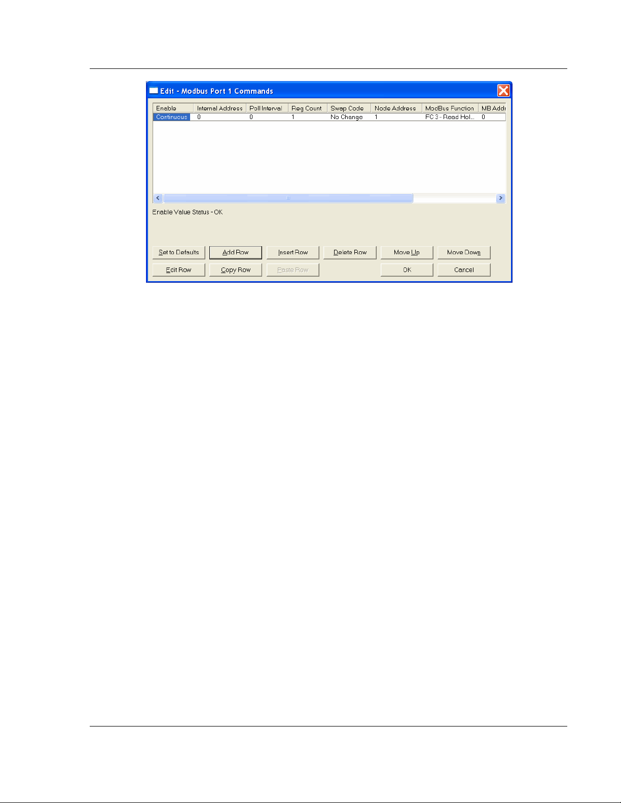
5 Double-clicking any icon will open an Edit dialog box with a table.
6 To add a row to the table, click the Add Row button.
Page 22 of 218 ProSoft Technology, Inc.
September 17, 2014
Page 23
PLX3x Series Configuring Your Gateway
Ethernet and Serial Gateways User Manual
ProSoft Technology, Inc. Page 23 of 218
September 17, 2014
Page 24
Configuring Your Gateway PLX3x Series
User Manual Ethernet and Serial Gateways
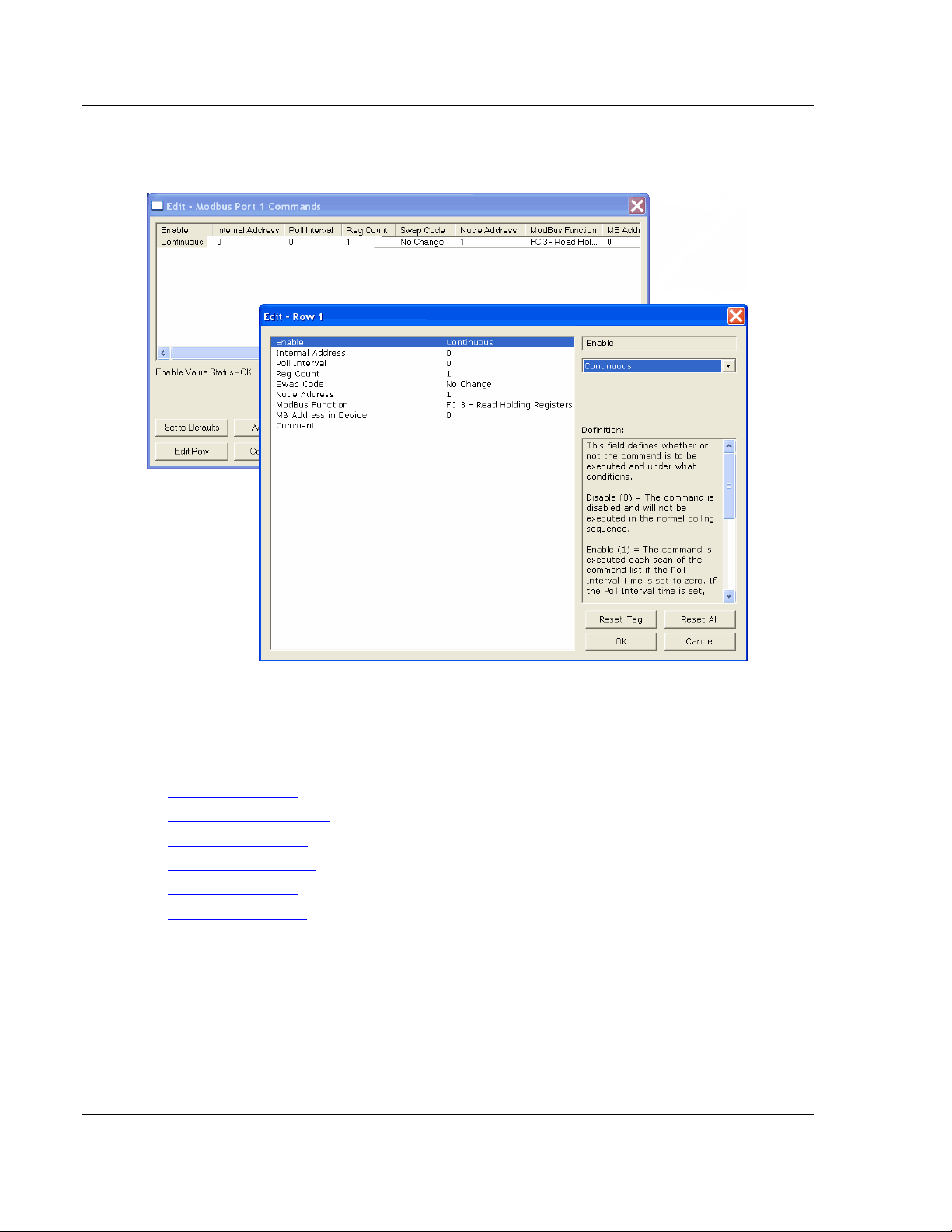
7 To edit the row, click the Edit Row button. This will open an Edit dialog box
where you can edit the row parameters.
8 When configuration is complete, download the configuration to the gateway.
9 For protocol-specific configuration information, see the Configuration section
in the appropriate protocol chapter of this manual:
EIP configuration (page 54)
MBTCP configuration (page 98)
MBS configuration(page125)
ASCII configuration (page 161)
SIE configuration (page 167)
PND configuration (page 194)
Page 24 of 218 ProSoft Technology, Inc.
September 17, 2014
Page 25

PLX3x Series Configuring Your Gateway
Ethernet and Serial Gateways User Manual
2.6 Using the CommonNet Data Map
Note: This is an advanced configuration feature and is not required for the basic operation of the
gateway.
The Data Map section allows data to be copied between areas in the gateway's
internal database.
The Data Map is especially useful for copying protocol-specific error and status
data from the gateway’s upper memory registers (address 4000 and up) to the
user-accessible memory registers (addresses 0 to 3999). The error and status
data copied into the user memory area can then be accessed by a remote
device, such as an HMI or processor.
Information about upper memory addresses where the gateway places protocolspecific error and status data can be found in the Diagnostics section in the
appropriate protocol chapter of this manual:
EIP diagnostics (page 70)
MBTCP diagnostics (page 105)
MBS diagnostics (page 132)
ASCII diagnostics (page 163)
SIE diagnostics (page 181)
PND diagnostics (page 213)
The Data Map can also be used to condense widely dispersed data into one
contiguous data block, for simplified access.
A maximum of 100 registers per Data Map command can be copied, and a
maximum of 200 separate copy commands can be configured.
The byte and/or word order can be rearranged during the copy process. For
example, by rearranging byte or word order, floating-point values can be
converted to the correct format for a different protocol.
ProSoft Technology, Inc. Page 25 of 218
September 17, 2014
Page 26
Configuring Your Gateway PLX3x Series
Parameter
Value
Description
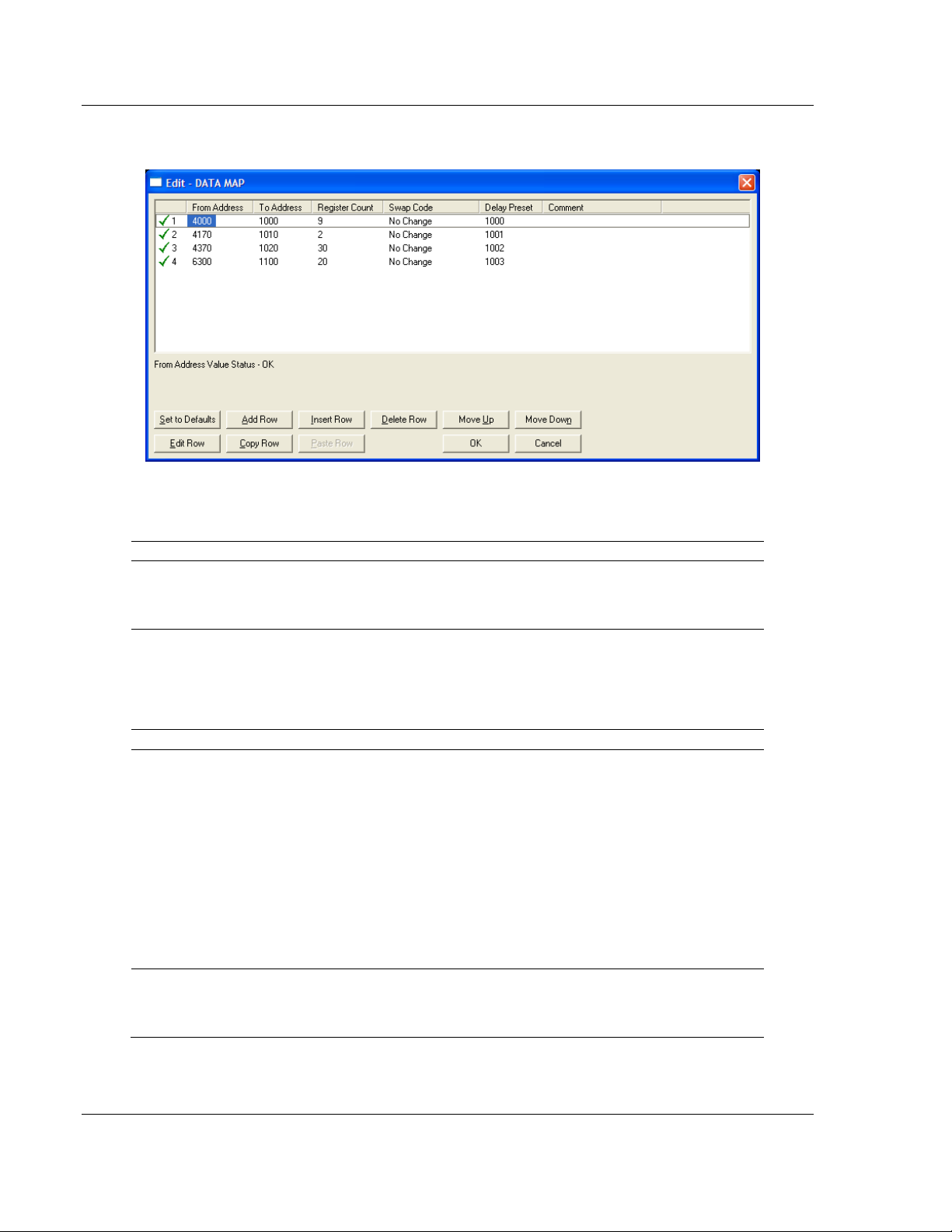
From Address
0 to highest
Status Data
address
This parameter specifies the beginning internal database
register address for the copy operation. This address can be
any valid address in the User Data Area or the Status Data
Area of the gateway.
To Address
0 to 3999
This parameter specifies the beginning destination register
address for the copy operation. This address must always be
within the User Data registers area. A destination address
must be specified that will not overwrite data that has been
stored in memory by one of the communication protocols
running on the gateway.
Register Count
1 to 100
This parameter specifies the number of registers to copy.
Swap Code
No Change
Word Swap
Word and Byte
Swap
Byte Swap
The order of the bytes in the registers may need to be
swapped during the copy process in order to change the
alignment of bytes between dissimilar protocols. This
parameter is helpful when dealing with floating-point or other
multi-register values, as there is no standard method of
storage of these data types in slave devices.
No change: No change is made in the byte ordering (1234 =
1234)
Word Swap: The words are swapped (1234=3412)
Word and Byte Swap: The words are swapped, then the
bytes in each word are swapped (1234=4321)
Byte Swap: The bytes in each word are swapped
(1234=2143)
Delay Preset
This parameter sets an interval for each Data Map copy
operation. The value that is specified for the Delay Preset is
not a fixed amount of time. It is the number of firmware scans
that must transpire between copy operations.
User Manual Ethernet and Serial Gateways
The following illustration shows an example Data Map.
The following table describes the parameters for configuring the Data Map.
Page 26 of 218 ProSoft Technology, Inc.
September 17, 2014
Page 27
PLX3x Series Configuring Your Gateway
Ethernet and Serial Gateways User Manual
2.7 Configuring an IP Address
Use this procedure to configure the Ethernet settings for your Gateway. You
must assign an IP address, subnet mask and gateway address. After you
complete this step, you can connect to the Gateway with an Ethernet cable.
Note: The PLX32 module contains two Ethernet ports. In this case, you would specify network
settings for the first Ethernet protocol on Enet P1 and another set of settings for the second
Ethernet Protocol on Enet P2.
1 Determine the network settings for your Gateway, with the help of your
network administrator if necessary. You will need the following information:
o IP address (fixed IP required) _____ . _____ . _____ . _____
o Subnet mask _____ . _____ . _____ . _____
o Gateway address _____ . _____ . _____ . _____
Note: The gateway address is optional, and is not required for networks that do not use a default
gateway.
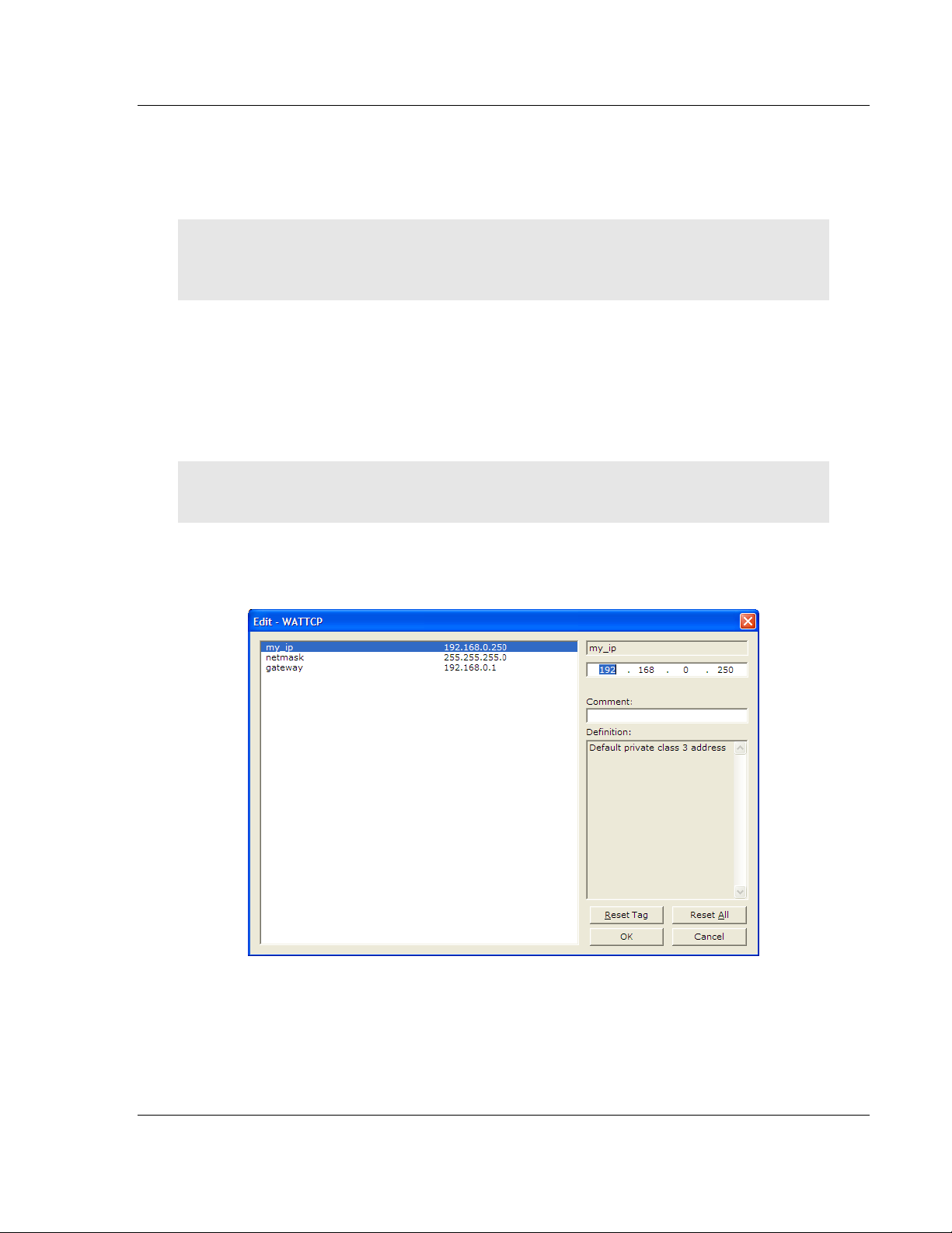
2 Double-click the ETHERNET CONFIGURATION icon. This action opens the
Edit dialog box. The IP address shown is the gateway default IP address.
3 Edit the values for my_ip, netmask (subnet mask) and gateway (default
gateway).
ProSoft Technology, Inc. Page 27 of 218
September 17, 2014
Page 28
Configuring Your Gateway PLX3x Series
User Manual Ethernet and Serial Gateways
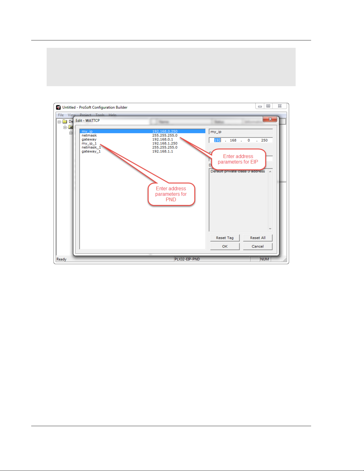
Note: If you are using a PLX32 module, you must specify values for both ports. My_ip is used to
specify values for the first protocol. For example, if you are configuring a PLX32-EIP-PND, you
would specify the network values for the EIP protocol first. A second set of values are available for
the second protocol; in this case, PND.
4 When you are finished editing, click OK to save your changes and return to
the ProSoft Configuration Builder window.
Page 28 of 218 ProSoft Technology, Inc.
September 17, 2014
Page 29
PLX3x Series Configuring Your Gateway
Ethernet and Serial Gateways User Manual
2.8 Downloading the Project to the Gateway
For the gateway to use the settings you configured, you must download (copy)
the updated Project file from your PC to the gateway.
To download the project file
1 In the tree view in ProSoft Configuration Builder, click once to select the
gateway.
2 Right-click the Gateway icon to open a shortcut menu. From the shortcut
menu, choose DOWNLOAD FROM PC TO DEVICE.
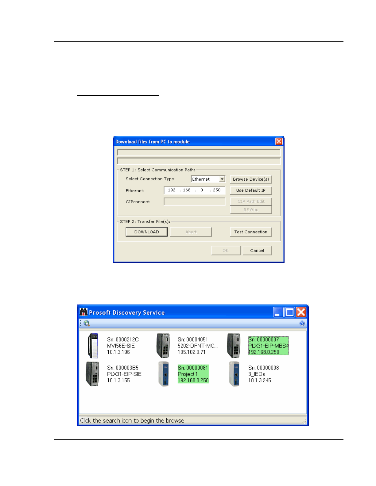
3 Click the BROWSE DEVICE(S) button to launch the ProSoft Discovery
Service window, which displays the ProSoft devices on the network and their
IP addresses.
ProSoft Technology, Inc. Page 29 of 218
September 17, 2014
Page 30
Configuring Your Gateway PLX3x Series
User Manual Ethernet and Serial Gateways
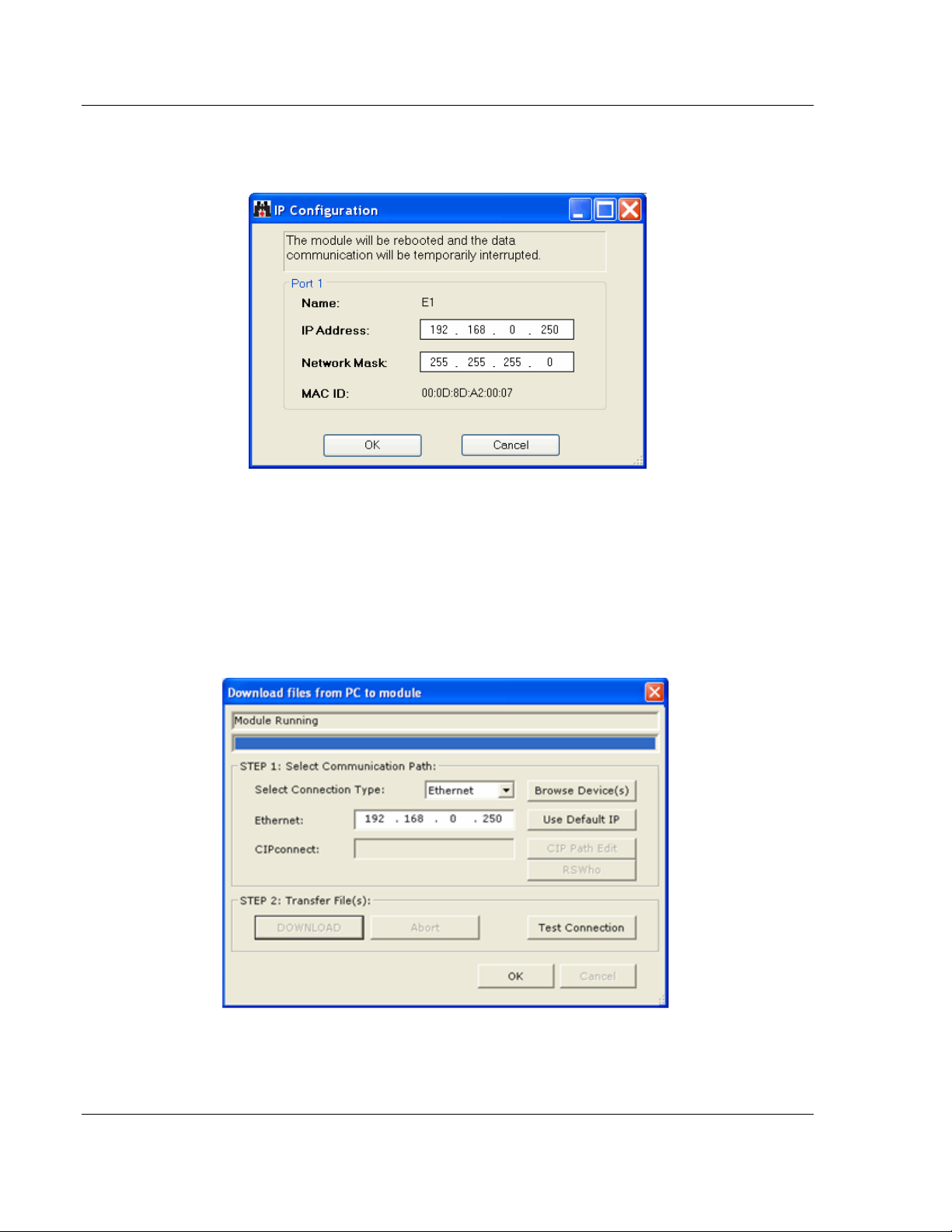
4 Right-click your PLX3x-series gateway and select IP Configuration from the
shortcut menu.
5 Enter the same IP address and network mask that you entered in the
Ethernet configuration of the gateway. Click OK. The gateway will reboot.
6 Close the ProSoft Discovery Service window to return to the Download dialog
box.
7 Click the DOWNLOAD button.
The gateway will perform a platform check to read and load its new settings.
When the platform check is complete, the status bar in the Download dialog
box will display the message Module Running.
Page 30 of 218 ProSoft Technology, Inc.
September 17, 2014
Page 31

PLX3x Series Configuring Your Gateway
Ethernet and Serial Gateways User Manual
2.9 Printing a Configuration File
1 Select the Gateway icon, and then click the right mouse button to open a
shortcut menu.
2 On the shortcut menu, choose VIEW CONFIGURATION. This action opens
the View Configuration window.
3 In the View Configuration window, open the FILE menu, and choose PRINT.
This action opens the Print dialog box.
4 In the Print dialog box, choose the printer to use from the drop-down list,
select printing options, and then click OK.
ProSoft Technology, Inc. Page 31 of 218
September 17, 2014
Page 32

PLX3x Series
User Manual Ethernet and Serial Gateways
Page 32 of 218 ProSoft Technology, Inc.
September 17, 2014
Page 33

PLX3x Series Diagnostics and Troubleshooting
Ethernet and Serial Gateways User Manual
3 Diagnostics and Troubleshooting
In This Chapter
LED Indicators .................................................................................. 34
Using Diagnostics in ProSoft Configuration Builder .......................... 36
Gateway Status Data in Upper Memory ........................................... 43
ProSoft Technology, Inc. Page 33 of 218
September 17, 2014
Page 34

Diagnostics and Troubleshooting PLX3x Series
LED
State
Description
PWR
(Power)
Off
Power is not connected to the power terminals or source is
insufficient to properly power the gateway (208 mA at 24 VDC is
required).
Solid Green
Power is connected to the power terminals.
FLT
(Fault)
Off
Normal operation.
Solid Red
A critical error has occurred. Program executable has failed or
has been user-terminated and is no longer running. Press
theResetbutton or cycle power to clear the error.
CFG
(Configuration)
Off
Normal operation.
Solid Amber
The unit is in configuration mode. Either a configuration error
exists, or the configuration file is currently being downloaded or
read. After power-up, the configuration is read, and the unit
implements the configuration values and initializes the hardware.
This occurs during power cycle or after the Reset button is
pressed.
ERR
(Error)
Off
Normal operation.
FlashingAmber
An error condition has been detected and is occurring on one of
the application ports. Check configuration and troubleshoot for
communication errors.
Solid Amber
This error flag is cleared at the start of each command attempt
(Master/Client) or on each receipt of data (slave/adapter/server);
so, if this condition exists, it indicates a large number of errors are
occurring in the application (due to bad configuration) or on one or
more ports (network communication failures).
NS
(Network
Status)
Off
No power or noIP address
Solid Red
Duplicate IP address
Solid Green
Connected
Flashing Red
Connection timeout
Flashing Green
IP address obtained; no established connections
Alternating Red
and Green Flash
Self-test
MS
(Module
Status)
Off
No power
Solid Red
Major fault
Solid Green
Device operational
Flashing Red
Minor fault
Flashing Green
Standby
Alternating Red
and Green Flash
Self-test
User Manual Ethernet and Serial Gateways
3.1 LED Indicators
Troubleshooting can be performed using several methods.
The first and quickest is to scan the LEDs on the gateway to determine the
existence and possibly the cause of a problem. The gateway’s LEDs provide
valuable information such as
The state of each port
System configuration errors
Application errors
Fault indications
3.1.1 Main Gateway LEDs
Page 34 of 218 ProSoft Technology, Inc.
September 17, 2014
Page 35

PLX3x Series Diagnostics and Troubleshooting
LED
State
Description
LINK/ACT
Off
No physical network connection is detected. No Ethernet
communication is possible. Check wiring and cables.
Solid Green
Physical network connection detected. This LED must be
ON solid for Ethernet communication to be possible
100 Mbit
Off
No activity on the port.
Flashing Amber
The Ethernet port is actively transmitting or receiving data.
LED
State
Description
RX
Off
No activity on the port.
Flashing Green
The port is actively receiving data.
TX
Off
No activity on the port.
Flashing Amber
The port is actively transmitting data.
Ethernet and Serial Gateways User Manual
3.1.2 Ethernet Port LEDs
3.1.3 Serial Port LEDs (for Gateways with Serial Ports)
ProSoft Technology, Inc. Page 35 of 218
September 17, 2014
Page 36

Diagnostics and Troubleshooting PLX3x Series
User Manual Ethernet and Serial Gateways
3.2 Using Diagnostics in ProSoft Configuration Builder
ProSoft Configuration Builder (PCB) has many useful tools to help you with
diagnostics and troubleshooting. You can use PCB to connect to your gateway
and retrieve current status values, configuration data and other valuable
information.
Tip: You can have a ProSoft Configuration Builder Diagnostics window open for more than one
gateway at a time.
To connect to the gateway’s communication port
1 Start PCB, and then select the gateway. Click the right mouse button to open
a shortcut menu.
2 On the shortcut menu, choose DIAGNOSTICS.
Page 36 of 218 ProSoft Technology, Inc.
September 17, 2014
Page 37

PLX3x Series Diagnostics and Troubleshooting
Ethernet and Serial Gateways User Manual
This opens the Diagnostics window.
If there is no response from the gateway, as in the example above, follow
these steps:
1 Click the Setup Connection button. In the Connection Setup dialog box,
select ETHERNET from the Select Connection Type dropdown menu. Type
in the gateway’s IP address in the Ethernet field.
2 Click the Connect button. Verify that the Ethernet is connected properly
between your computer’s communication port and the gateway.
If you are still not able to establish a connection, contact ProSoft Technology
for assistance.
ProSoft Technology, Inc. Page 37 of 218
September 17, 2014
Page 38

Diagnostics and Troubleshooting PLX3x Series
User Manual Ethernet and Serial Gateways
3.2.1 Diagnostics Menu
The Diagnostics menu is arranged as a tree structure, with the Main menu at the
top of the tree, and one or more submenus for each menu command.
The menu commands available will depend on the protocol combination of your
gateway.
Caution: Some of the commands available to you from this menu are designed for advanced
debugging and system testing only, and can cause the gateway to stop communicating with the
processor or with other devices, resulting in potential data loss or other communication failures.
Use these commands only if you fully understand their potential effects, or if you are specifically
directed to do so by ProSoft Technology Technical Support Engineers.
Page 38 of 218 ProSoft Technology, Inc.
September 17, 2014
Page 39

PLX3x Series Diagnostics and Troubleshooting
Menu
Command
Submenu
Command
Description
Module
Version
Displays the gateway’s current software version and other
important values. You may be asked to provide this information
when calling for technical support.
Data Map
Displays the gateway’s Data Map configuration.
Database
View
ASCII
Displays the contents of the gateway’s database in ASCII
character format.*
Decimal
Displays the contents of the gateway’s database in decimal
number format.*
Hex
Displays the contents of the gateway’s database in hexadecimal
number format.*
Float
Displays the contents of the gateway’s database in floating-point
number format.*
Ethernet and Serial Gateways User Manual
The following menu commands are common to all PLX3x-series gateways:
* Use the scroll bar on the right edge of the window to navigate through the database. Each page
displays 100 words of data. The total number of pages available depends on your gateway’s
configuration.
ProSoft Technology, Inc. Page 39 of 218
September 17, 2014
Page 40

Diagnostics and Troubleshooting PLX3x Series
User Manual Ethernet and Serial Gateways
3.2.2 Capturing a Diagnostic Session to a Log File
You can capture anything you do in a Diagnostics session to a log file. This
feature can be useful for troubleshooting and record-keeping purposes, and for
communication with ProSoft Technology’s technical support team.
1 Open a Diagnostics window.
2 To log a Diagnostics session to a text file, click the Log File button on the
toolbar at the top of the Diagnostics window. Click the button again to stop
the capture.
3 To view the log file created, click the View Log File button. The log file will
open as a text file, which can be renamed and saved to a different location.
4 To email the log file to ProSoft Technology’s technical support team, click the
Email Log File button. (For this to work, Microsoft Outlook must be installed
on your PC.)
5 If you do multiple sequential captures, PCB will append data from a new
capture to the end of the previously captured data. If you want previous data
to be cleared from the log file each time you start a new capture, click the
Clear Data button.
Page 40 of 218 ProSoft Technology, Inc.
September 17, 2014
Page 41

PLX3x Series Diagnostics and Troubleshooting
Ethernet and Serial Gateways User Manual
3.2.3 Using the Data Analyzer (Serial Protocols Only)
The Data Analyzer is an extremely valuable troubleshooting tool available in
PCB. It allows you to “see” the data packets entering and leaving the serial ports
on the gateway. You can also capture this data to a log file.
Note: The PCB Data Analyzer is for serial ports only. To analyze data traffic on an Ethernet port,
we recommend using a network protocol analyzer available on the Internet, such as Wireshark.
To use the Data Analyzer
1 Open the Diagnostics window in PCB.
2 On the toolbar at the top of the window, click the Setup Data Analyzer
button.
3 In the Data Analyzer Setup dialog box, specify the time tick interval, the serial
port number, and whether the data packet contents should be displayed in
hexadecimal number or ASCII character format. Click OK.
Note: The time tick is a symbol (_TT_) displayed on the Data Analyzer screen that allows you to
estimate time intervals during a Data Analyzer session. The time tick will print at the time interval
you specify in the Data Analyzer Setup dialog box. For example, if you select 10 mS Ticks, it will
print every 10 milliseconds.
ProSoft Technology, Inc. Page 41 of 218
September 17, 2014
Page 42

Diagnostics and Troubleshooting PLX3x Series
User Manual Ethernet and Serial Gateways
4 If you wish to capture the Data Analyzer session to a log file, click the Log
File button.
5 Click the Start Data Analyzer button to start the Data Analyzer. Click it again
to stop it.
6 The example below is part of a capture of standard Modbus data packets. It
is displayed in hexadecimal number format.
7 Data LEAVING the serial port is enclosed in angle brackets <>.
8 Data ENTERING the port is enclosed in square brackets [ ].
9 Each set of brackets holds one word (2 bytes) of data.
For Modbus protocol users: To interpret the data packets, refer to the Modbus Protocol
Specification, which can be found in this manual (page 139) or at www.modbus.org.
Page 42 of 218 ProSoft Technology, Inc.
September 17, 2014
Page 43

PLX3x Series Diagnostics and Troubleshooting
Register Address
Description
4000 through 4001
Program Cycle Counter
4002 through 4004
Product Code (ASCII)
4005 through 4009
Product Revision (ASCII)
4010 through 4014
Operating System Revision (ASCII)
4015 through 4019
OS Run Number (ASCII)
Ethernet and Serial Gateways User Manual
3.3 Gateway Status Data in Upper Memory
The gateway places useful status data in dedicated upper memory locations in its
internal database. The Data Map functionality of the gateway can be used to map
this data into the normal user data range of the gateway’s database (registers 0
through 3999). It can be accessed by remote devices, such as HMIs or
processors. See Using the CommonNet Data Map (page 25).
3.3.1 General Gateway Status Data in Upper Memory
The following table describes the contents of the gateway’s general status data
area.
3.3.2 Protocol-Specific Status Data in Upper Memory
The gateway also has upper memory locations for protocol-specific status data.
Information about upper memory addresses where the gateway places status
data for its protocol drivers can be found in the Diagnostics sections of the
protocol chapters:
EIP diagnostics (page 70)
MBTCP diagnostics (page 105)
MBS diagnostics (page 132)
ASCII diagnostics (page 163)
SIE diagnostics (page 181)
PND diagnostics (page 213)
ProSoft Technology, Inc. Page 43 of 218
September 17, 2014
Page 44

PLX3x Series
User Manual Ethernet and Serial Gateways
Page 44 of 218 ProSoft Technology, Inc.
September 17, 2014
Page 45

PLX3x Series Hardware Information
Ethernet and Serial Gateways User Manual
4 Hardware Information
In This Chapter
Hardware Specifications ................................................................... 46
Serial Port Cables (for Gateways with Serial Ports).......................... 48
ProSoft Technology, Inc. Page 45 of 218
September 17, 2014
Page 46

Hardware Information PLX3x Series
Specification
Description
Power Supply
24 VDC nominal
10 VDC to 36 VDC allowed
Positive, Negative, GND Terminals
Current Load
208mA normal @ 24 VDC normal
300 mA maximum @ 36 VDC maximum
Operating Temperature
-25°C to 70°C (-13°F to 158°F)
Storage Temperature
-40°C to 80°C (-40°F to 176°F)
Relative Humidity
5% to 95% RH with no condensation
Dimensions
(Height x Width x
Depth)
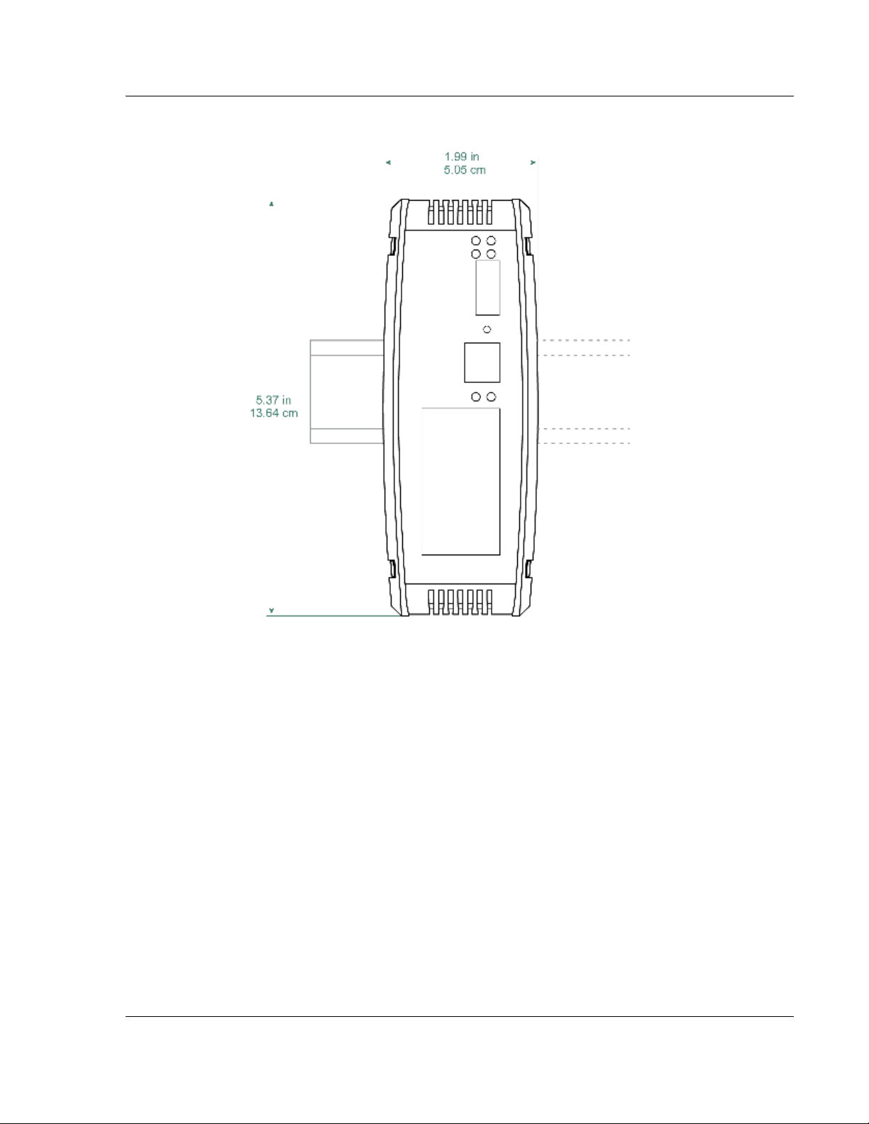
Standard: 5.38 in x 1.99 in x 4.38 in
(13.67 cm x 5.05 cm x 11.13 cm)
LED Indicators
(On all gateways)
Configuration (CFG) and Error (ERR) Communication
Status
Power (PWR) and Hardware Fault (FLT)
Network Status (NS) EtherNet/IP™ Class I or Class III
Connection Status (EtherNet/IP Only)
Module Status (MS) Module Configuration Status
(EtherNet/IP Only)
Ethernet Communication Port Link/Activity and 100mbit
Serial Communication Port Receive (RX) and Transmit
(TX)
Ethernet Port (S)
10/100Mbit full-duplex RJ45 Connector Electrical Isolation
1500 Vrms at 50 Hz to 60 Hz for 60 seconds, applied as
specified in section 5.3.2 of IEC 60950: 1991
Ethernet Broadcast Storm Resiliency = less than or equal
to 5000 [ARP] frames-per-second and less than or equal to
5 minutes duration
Serial Port Isolation
2500 Vrms port signal isolation per UL 1577
serial port communication signal uses RF(Radio
Frequency) modulation signal as isolation media, IC chip
model is Silicon Labs Si844x(Si8440,Si8441,Si8442).
Shipped With Each Unit
2.5 mm screwdriver
ProSoft Solutions DVD
J180 Power Connector
(1 to 4) RJ45-DB9M Serial Adapter Cable (serial protocol
only)
(1 to 4) DB9 to Screw Terminal Adapter (serial protocol
only)
User Manual Ethernet and Serial Gateways
4.1 Hardware Specifications
Page 46 of 218 ProSoft Technology, Inc.
September 17, 2014
Page 47

PLX3x Series Hardware Information
Type
Specifications
Serial Port Isolation
2500 Vrms port signal isolation per UL 1577
serial port communication signal uses RF(Radio
Frequency) modulation signal as isolation media, IC
chip model is Silicon Labs Si844x
(Si8440,Si8441,Si8442).
Serial Port Protection
RS-485/422 port interface lines TVS diode protected
at +/- 27V standoff voltage.
RS-232 port interface lines fault protected to +/- 36V
power on, +/- 40V power off.
Ethernet and Serial Gateways User Manual
4.1.1 Serial Port Specifications
ProSoft Technology, Inc. Page 47 of 218
September 17, 2014
Page 48

Hardware Information PLX3x Series
User Manual Ethernet and Serial Gateways
4.2 Serial Port Cables (for Gateways with Serial Ports)
This section contains information on the cable and pin assignments for the
PLX3x gateway's serial ports (RS-232/422/485). The PLX3x gateway may come
with one or four serial ports, depending on the configuration purchased.
Example: The PLX31-EIP-MBS4 gateway contains four serial communication ports
The PLX31-EIP-MBS gateway contains one serial communication port.
Each physical serial port has a RJ45 jack connector. A six-inch RJ45 to DB9Male
adapter cable is provided for each serial port. The DB9Male adapter cable
provides connections for RS-232, wired as Data Terminal Equipment (DTE), RS422 and RS-485.
4.2.1 RS-232 - Null Modem (DTE with Hardware Handshaking)
This type of connection is used when the device connected to the gateway
requires hardware handshaking (control and monitoring of modem signal lines).
To enable hardware handshaking, set the port configuration to use RTS/CTS
handshaking. (For MBS protocol, set the Use CTS Line parameter to Yes. For
ASCII protocol, set the Handshaking parameter to Yes.)
Page 48 of 218 ProSoft Technology, Inc.
September 17, 2014
Page 49

PLX3x Series Hardware Information
Ethernet and Serial Gateways User Manual
4.2.2 RS-232 - Null Modem (DTE without Hardware Handshaking)
This type of connection can be used to connect the gateway to a computer or
field device communication port.
Note: If the port is configured to use RTS/CTS handshaking, then a jumper is required between the
RTS and the CTS line on the gateway connection.
4.2.3 RS-232 - DTE to DCE Modem Connection
This type of connection is required between the gateway and a modem or other
communication device.
For most modem applications, RTS/CTS handshaking should be enabled in the
port configuration.
ProSoft Technology, Inc. Page 49 of 218
September 17, 2014
Page 50

Hardware Information PLX3x Series
User Manual Ethernet and Serial Gateways
4.2.4 RS-422 Interface Connections
The following illustration applies when the RS-422 interface is selected.
4.2.5 RS-485 Interface Connections
The following illustration applies when the RS-485 interface is selected.
NOTE: This type of connection is commonly called a RS-485 half-duplex, 2-wire connection. If you
have RS-485 4-wire, full-duplex devices, they can be connected to the gateway's serial ports by
wiring together the TxD+ and RxD+ from the two pins of the full-duplex device to Pin 1 on the
gateway and wiring together the TxD- and RxD- from the two pins of the full-duplex device to Pin 8
on the gateway. As an alternative, you could try setting the gateway to use the RS-422 interface
and connect the full-duplex device according to the RS-422 wiring diagram. For additional
assistance, please contact ProSoft Technical Support.
Page 50 of 218 ProSoft Technology, Inc.
September 17, 2014
Page 51

PLX3x Series EIP Protocol
Ethernet and Serial Gateways User Manual
5 EIP Protocol
In This Chapter
EIP Functional Overview .................................................................. 52
EIP Configuration.............................................................................. 54
EIP Diagnostics ................................................................................ 70
EIP Reference .................................................................................. 77
This chapter contains information specific to the PLX3x-series gateway
EtherNet/IP (EIP) protocol driver.
ProSoft Technology, Inc. Page 51 of 218
September 17, 2014
Page 52

EIP Protocol PLX3x Series
Class
Connection Type
Number of Connections
Class 1
I/O
Depends on the gateway model:
PLX31-EIP-MBTCP - 2 connections
PLX31-EIP-MBS - 2 connections
PLX31-EIP-MBS4 - 8 connections
PLX31-EIP-ASCII - 1 connection
PLX31-EIP-ASCII4 - 4 connections
PLX31-EIP-SIE – 2 connections
Class 3
Connected Client
2
Unconnected Client
1
Server
5
User Manual Ethernet and Serial Gateways
5.1 EIP Functional Overview
The PLX3x-series EIP gateway can be used to interface many different
protocols into the Rockwell Automation family of processors as well as other
software-based solutions.
The following illustration shows the functionality of the EtherNet/IP protocol.
The EIP driver supports the following connections:
Page 52 of 218 ProSoft Technology, Inc.
September 17, 2014
Page 53

PLX3x Series EIP Protocol
Number of Clients Supported
Connected Clients: 2
Unconnected Clients: 1
Command List
Support for 100 commands per Client, each configurable for
command type, IP address, register to/from addressing and
word/bit count.
Polling of Command List
User-configurable polling of commands, including disabled,
continuous and on change of data (write only).
Other Configurable Parameters
Number of Commands (up to 100 per Client)
Min Command Delay
Response Timeout
Retry Count
Command Error Pointer
Ethernet and Serial Gateways User Manual
5.1.1 EtherNet/IP™ Client
In Client mode, the gateway controls the read/write data transfer between the
gateway and other EtherNet/IP devices.
ProSoft Technology, Inc. Page 53 of 218
September 17, 2014
Page 54

EIP Protocol PLX3x Series
Data Type
Tag Name
Length of Each Element in
CIP Message
Array Range for 4000
Element Database
BOOL
BOOLData[ ]
1
0 to 63999
Bit Array
BITAData[ ]
4
0 to 1999
SINT
SINTData[ ]
1
0 to 7999
INT
INT_Data[ ]
2
0 to 3999
DINT
DINTData[ ]
4
0 to 1999
REAL
REALData[ ]
4
0 to 1999
Database
Address
CIP Integer
CIP Boolean
CIP Bit Array
CIP Byte
CIP DINT
CIP Real
0
Int_data[0]
BoolData[0]
BitAData[0]
SIntData[0]
DIntData[0]
RealData[0]
999
Int_data[999]
BoolData[15984]
SIntData[1998]
1000
Int_data[1000]
BoolData[16000]
BitAData[500]
SIntData[2000]
DIntData[500]
RealData[500]
1999
Int_data[1999]
BoolData[31984]
SIntData[3998]
2000
Int_data[2000]
BoolData[32000]
BitAData[1000]
SIntData[4000]
DIntData[1000]
RealData[1000]
2999
Int_data[2999]
BoolData[47984]
SIntData[5998]
3000
Int_data[3000]
BoolData[48000]
BitAData[1500]
SIntData[6000]
DIntData[1500]
RealData[1500]
3999
Int_data[3999]
BoolData[63999]
SIntData[9998]
User Manual Ethernet and Serial Gateways
5.2 EIP Configuration
5.2.1 EIP Class 3 Server Connection
The EIP Class 3 Server Connection is used when the gateway is acting as a
server (slave) device responding to message instructions initiated from a Client
(Master) device such as an HMI, DCS, or PLC5.
Configuring EIP Class 3 Server Connections in PCB
The PLX3x Server connection file size is user selectable for 100 or 1000
integers. If a value of 100 is selected valid registers will be from N10:0 to N10:99.
If a value of 1000 is selected valid registers will be from N10:0 to N10:999.
Accessing the Gateway’s Internal Memory
The following tables define the relationship of the gateway’s internal database to
the addresses required in the MSG instructions:
MSG Instruction Type - CIP
Page 54 of 218 ProSoft Technology, Inc.
September 17, 2014
Page 55

PLX3x Series EIP Protocol
Database Address
File size 100
Database Address
File size 100
0
N10:0
0
N10:0
999
N19:99
999
N19:99
1000
N20:0
1000
N20:0
1999
N29:99
1999
N29:99
2000
N30:0
2000
N30:0
Command
Function
Definition
Supported in Server
0x00
N/A
Protected Write
X
0x01
N/A
Unprotected Read
X
0x02
N/A
Protected Bit Write
X
0x05
N/A
Unprotected Bit Write
X
0x08
N/A
Unprotected Write
X
Command
Function
Definition
Supported in Server
0x0F
0x00
Word Range Write (Binary Address)
X
0x0F
0x01
Word Range Read (Binary Address)
X
0x0F
Typed Range Read (Binary Address)
X
0x0F
Typed Range Write (Binary Address)
X
0x0F
0x26
Read-Modify-Write (Binary Address)
0x0F
0x00
Word Range Write (ASCII Address)
X
0x0F
0x01
Word Range Read (ASCII Address)
X
0x0F
0x26
Read-Modify-Write (ASCII Address)
Command
Function
Definition
Supported in Server
0x0F
0xA1
Protected Typed Logical Read With Two
Address Fields
X
0x0F
0xA2
Protected Typed Logical Read With Three
Address Fields
X
0x0F
0xA9
Protected Typed Logical Write With Two
Address Fields
X
0x0F
0xAA
Protected Typed Logical Write With Three
Address Fields
X
0x0F
0xAB
Protected Typed Logical Write With Mask (Three Address Fields)
Ethernet and Serial Gateways User Manual
MSG Instruction Type - PCCC
EtherNet/IP Explicit Messaging Server Command Support
The following commands are supported in the PLX3x gateway.
Basic Command Set Functions
PLC-5 Command Set Functions
SLC-500 Command Set Functions
ProSoft Technology, Inc. Page 55 of 218
September 17, 2014
Page 56

EIP Protocol PLX3x Series
User Manual Ethernet and Serial Gateways
5.2.2 EIP Class 1 Connection
The EIP Class 1 Connection is used when the gateway acts as an EIP adapter
transferring data to and from a PLC (the EIP scanner), using a direct I/O
connection. Direct I/O connections can be used to transfer large amounts of data
quickly.
The PLX3x-series EIP gateway can handle up to eight I/O connections
(depending on the model), each with 248 words of input data and 248 words of
output data. Rockwell Automation customers running RSLogix 5000 v.20 and
higher can take advantage of premier integration with an Add-on profile.
Adding the Gateway to RSLogix5000 v.20
1. Open up RSLinx and browse to the PLX3x gateway.
2. Open up a short cut window by right clicking on the gateway.
3. Select Upload EDS from device.
Note: RSLogix5000 may need to be restarted in order to complete the installation.
4. Once RSLogix5000 has been restarted, add a New Module under the
EtherNet/IP bridge in the I/O tree.
5. In the Module Type Vendor Filters window set the filter options to ProSoft
Technology.
6. Select the corresponding PLX3x gateway and click Create
7. In the next window set the IP address to the address of the PLX3x
gateway. To add I/O connections click the Change button.
8. Here up to eight I/O connections can be added. The I/O connections have
a fixed size of 496 bytes of input data and 496 bytes of output data. When
finished click ok.
9. In the Module properties window each I/O connection can be configured
with its own RPI time.
Adding the Gateway to RSLogix5000 v.19 and Below
1. Add a New Module under the EtherNet/IP bridge in the I/O tree.
2. Click Find and search for Generic EtherNet Bridge click Create.
3. Set the IP address to the gateway. This creates the communication path
from the processor to the PLX3x gateway
Page 56 of 218 ProSoft Technology, Inc.
September 17, 2014
Page 57

PLX3x Series EIP Protocol
Parameter
Value Range
Description
Input Data
Address
0-3999
This parameter specifies the starting address within the
gateway’s virtual database for data transferred from the
PLC to the module
Input Size
0-248
This parameter specifies the number of Integers being
transferred to the PLC's input image (248 integers max)
Output Data
Address
0-3999
This parameter specifies the starting address within the
gateway’s virtual database for data transferred from the
module to the PLC
Output Size
0-248
This parameter specifies the number of integers being
transferred to the PLC's output image (248 integers max)
Ethernet and Serial Gateways User Manual
4. Next add a New Module under the Generic EtherNet Bridge and add a
CIP-Connection. Here the parameters for the I/O connection are
specified. The input and output sizes need to match the input and output
sizes configured in PCB. The Address field value represents the
connection number in PCB. By default all of the connections have 248
Input words, 248 Output words, and 0 Configuration words. The Comm
format should be set to Data type INT, and the Assembly instances
should be "1" for input, "2" for output, and "4" for configuration.
5. A CIP Connection will need to be added and configured for each I/O
connection.
Configuring EIP Class 1 Connections in PCB
There are four configurable parameters for each I/O connection in PCB.
ProSoft Technology, Inc. Page 57 of 218
September 17, 2014
Page 58

EIP Protocol PLX3x Series
Parameter
Value
Description
Minimum
Command
Delay
0 to 65535
milliseconds
This parameter specifies the number of milliseconds to wait
between the initial issuances of a command. This parameter can
be used to delay all commands sent to servers to avoid
"flooding" commands on the network. This parameter does not
affect retries of a command as they will be issued when failure is
recognized.
Response
Timeout
0 to 65535
milliseconds
This parameter specifies the amount of time in milliseconds that
a Client will wait before re-transmitting a command if no
response is received from the addressed server. The value to
use depends on the type of communication network used, and
the expected response time of the slowest device connected to
the network.
Retry Count
0 to 10
This parameter specifies the number of times a command will be
retried if it fails.
User Manual Ethernet and Serial Gateways
5.2.3 EIP Class 3 Client/UClient [x] Connection
The PLX3x gateway supports two connected Clients and one unconnected Client
(most devices use connected Clients; be sure refer to the user manual of the
target device for verification).
The EIP Class 3 Client [x] Connections are used when the gateway is acting as a
Client/Master initiating message instructions to the server/slave devices. The
PLX3x EIP protocol supports three Connected Client Connections. Typical
applications include SCADA systems, and SLC communication.
The EIP Class 3 UClient Connection is used when the gateway is acting as a
Client/Master initiating message Instructions to the server/slave devices. The
PLX3x EIP protocol supports one Unconnected Client Connection. Unconnected
messaging is a type of Ethernet/IP explicit messaging that uses TCP/IP
implementation. Certain devices, such as the AB Power Monitor 3000 series B,
support unconnected messaging. Check your device documentation for further
information about its Ethernet/IP implementation.
Class 3 Client/UClient [x]
This section specifies the configuration for the EIP Client (Master) device on the
network port.
Page 58 of 218 ProSoft Technology, Inc.
September 17, 2014
Page 59

PLX3x Series EIP Protocol
Ethernet and Serial Gateways User Manual
Class 3 Client/UClient[x] Commands
There is a separate command list for each of the different message types
supported by the protocol. Each list is processed from top to bottom, one after
the other, until all specified commands are completed, and then the polling
process begins over again.
This section defines the EtherNet/IP commands to be issued from the gateway
to server devices on the network. These commands can be used for data
collection and/or control of devices on the TCP/IP network.
In order to interface the virtual database with Rockwell Automation
Programmable Automation Controllers (PACs), Programmable Logic Controllers
(PLCs), or other EtherNet/IP server devices, you must construct a command list.
The following tables describe the command list parameters for each message
type.
ProSoft Technology, Inc. Page 59 of 218
September 17, 2014
Page 60

EIP Protocol PLX3x Series
Parameter
Value
Description
Enable
Enable
Disable
Conditional Write
Specifies if the command should be executed and under
what conditions.
Enable - The Command is executed each scan of the
command list
Disable- The command is disabled and will not be
executed
Conditional Write - The Command executes only if the
internal data associated with the command changes
Internal
Address
0 to 3999
Specifies the database address in the modules internal
database to be associated with the command. If the
command is a read function, the data received in the
response message is placed at the specified location. If
the command is a write function data used in the
command is sourced from specified data area.
Poll Interval
0-65535
Specifies the minimum interval to execute continuous
commands. The parameter is entered in 1/10 of a second.
If a value of 100 is entered for a command the command
executes no more frequently than every 10 seconds.
Reg Count
Specifies the number of data points to be read from or
written to the target device.
Swap Code
None
Word swap
Word and Byte
swap
Byte swap
Specifies if the data from the server is to be ordered
differently than it was received. This parameter is typically
used when dealing with floating-point or other multiregister values.
None - No change is made (abcd)
Word swap - The words are swapped (cdab)
Word and Byte swap - The words and bytes are
swapped (dcba)
Byte swap - The bytes are swapped (badc)
IP Address
xxx.xxx.xxx.xxx
Specifies the IP address of the target device to be
addressed by this command
Slot
-1
Use a value of -1 when interfacing to an SLC 5/05. These
devices do not have a slot parameter. When addressing a
processor in a ControlLogix or CompactLogix rack, the
slot number corresponds to the slot in the rack containing
the controller being addressed.
Func Code
501
509
Specifies the function code to be used in the command.
501 – Protected Typed Read
509 – Protected Typed Write
File Type
Binary
Counter
Timer
Control
Integer
Float
ASCII
String
Status
Specifies the file type to be associated with the command.
File Number
-1
Specifies the PLC-5 file number to be associated with the
command. If a value of -1 is entered for the parameter,
the field will not be used in the command, and the default
User Manual Ethernet and Serial Gateways
Class 3 Client/UClient [x] Commands SLC500 2 Address Fields
Page 60 of 218 ProSoft Technology, Inc.
September 17, 2014
Page 61

PLX3x Series EIP Protocol
Parameter
Value
Description
file will be used.
Element
Number
Specifies the element in the file where the command will
start.
Comment
This field can be used to give a 32 character comment to
the command.
Ethernet and Serial Gateways User Manual
ProSoft Technology, Inc. Page 61 of 218
September 17, 2014
Page 62

EIP Protocol PLX3x Series
Parameter
Value
Description
Enable
Enable
Disable
Conditional Write
Specifies if the command should be executed and
under what conditions.
Enable - The Command is executed each scan of the
command list
Disable- The command is disabled and will not be
executed
Conditional Write - The Command executes only if
the internal data associated with the command changes
Internal Address
0 to 3999
Specifies the database address in the modules internal
database to be associated with the command. If the
command is a read function, the data received in the
response message is placed at the specified location. If
the command is a write function data used in the
command is sourced from specified data area.
Poll Interval
0 to 65535
Specifies the minimum interval to execute continuous
commands. The parameter is entered in 1/10 of a
second. If a value of 100 is entered for a command the
command executes no more frequently than every 10
seconds.
Reg Count
Specifies the number of data points to be read from or
written to the target device.
Swap Code
None
Word swap
Word and Byte
swap
Byte swap
Specifies if the data from the server is to be ordered
differently than it was received. This parameter is
typically used when dealing with floating-point or other
multi-register values.
None - No change is made (abcd)
Word swap - The words are swapped (cdab)
Word and Byte swap - The words and bytes are
swapped (dcba)
Byte swap - The bytes are swapped (badc)
IP Address
xxx.xxx.xxx.xxx
Specifies the IP address of the target device to be
addressed by this command
Slot
-1
Use a value of -1 when interfacing to an SLC 5/05.
These devices do not have a slot parameter. When
addressing a processor in a ControlLogix or
CompactLogix, the slot number corresponds to the slot
in the rack containing the controller being addressed.
Func Code
502
510
511
Specifies the function code to be used in the command.
502 - Protected Typed Read
510 - Protected Typed Write
511 - Protected Typed Write w/Mask
User Manual Ethernet and Serial Gateways
Class 3 Client/UClient [x] Commands SLC500 3 Address Fields
This command is typically used when accessing data in a Timer or Counter. I.e.
T.1.1.2 is the address of the accumulator in Timer 1.
Page 62 of 218 ProSoft Technology, Inc.
September 17, 2014
Page 63

PLX3x Series EIP Protocol
Parameter
Value
Description
File Type
Binary
Counter
Timer
Control
Integer
Float
ASCII
String
Status
Specifies the file type to be associated with the
command.
File Number
-1
Specifies the SLC 500 file number to be associated with
the command. If a value of -1 is entered for the
parameter, the field will not be used in the command,
and the default file will be used.
Element
Number
Specifies the element in the file where the command
will start.
Sub Element
Specifies the sub-element to be used with the
command. Refer to the AB documentation for a list of
valid sub-element codes.
Comment
This field can be used to give a 32 character comment
to the command.
Ethernet and Serial Gateways User Manual
ProSoft Technology, Inc. Page 63 of 218
September 17, 2014
Page 64

EIP Protocol PLX3x Series
Parameter
Value
Description
Enable
Enable
Disable
Conditional Write
Specifies if the command should be executed and
under what conditions.
Enable - The Command is executed each scan of the
command list
Disable- The command is disabled and will not be
executed
Conditional Write - The Command executes only if
the internal data associated with the command changes
Internal Address
0 to 3999
Specifies the database address in the modules internal
database to be associated with the command. If the
command is a read function, the data received in the
response message is placed at the specified location. If
the command is a write function data used in the
command is sourced from specified data area.
Poll Interval
0 to 65535
Specifies the minimum interval to execute continuous
commands. The parameter is entered in 1/10 of a
second. If a value of 100 is entered for a command the
command executes no more frequently than every 10
seconds.
Reg Count
Specifies the number of data points to be read from or
written to the target device.
Swap Code
None
Word swap
Word and Byte
swap
Byte swap
Specifies if the data from the server is to be ordered
differently than it was received. This parameter is
typically used when dealing with floating-point or other
multi-register values.
None - No change is made (abcd)
Word swap - The words are swapped (cdab)
Word and Byte swap - The words and bytes are
swapped (dcba)
Byte swap - The bytes are swapped (badc)
IP Address
xxx.xxx.xxx.xxx
Specifies the IP address of the target device to be
addressed by this command
Slot
-1
Use a value of -1 when interfacing to a PLC5 These
devices do not have a slot parameter. When addressing
a processor in a ControlLogix or CompactLogix, the slot
number corresponds to the slot in the rack containing
the controller being addressed.
Func Code
100
101
102
Specifies the function code to be used in the command.
100 - Word Range Write
101 - Word Range Read
102 - Read-Modify-Write
File Type
Binary
Counter
Timer
Control
Integer
Float
ASCII
String
Status
Specifies the file type to be associated with the
command.
File Number
-1
Specifies the PLC5 file number to be associated with
User Manual Ethernet and Serial Gateways
Class 3 Client/UClient [x] Commands PLC5 Binary
Page 64 of 218 ProSoft Technology, Inc.
September 17, 2014
Page 65

PLX3x Series EIP Protocol
Parameter
Value
Description
the command. If a value of -1 is entered for the
parameter, the field will not be used in the command,
and the default file will be used.
Element
Number
Specifies the element in the file where the command
will start.
Sub Element
Specifies the sub-element to be used with the
command. Refer to the AB documentation for a list of
valid sub-element codes.
Comment
This field can be used to give a 32 character comment
to the command.
Ethernet and Serial Gateways User Manual
ProSoft Technology, Inc. Page 65 of 218
September 17, 2014
Page 66

EIP Protocol PLX3x Series
Parameter
Value
Description
Enable
Enable
Disable
Conditional Write
Specifies if the command should be executed and
under what conditions.
Enable - The Command is executed each scan of the
command list
Disable- The command is disabled and will not be
executed
Conditional Write - The Command executes only if
the internal data associated with the command changes
Internal Address
0 to 3999
Specifies the database address in the modules internal
database to be associated with the command. If the
command is a read function, the data received in the
response message is placed at the specified location. If
the command is a write function data used in the
command is sourced from specified data area.
Poll Interval
0 to 65535
Specifies the minimum interval to execute continuous
commands. The parameter is entered in 1/10 of a
second. If a value of 100 is entered for a command the
command executes no more frequently than every 10
seconds.
Reg Count
Specifies the number of data points to be read from or
written to the target device.
Swap Code
None
Word swap
Word and Byte
swap
Byte swap
Specifies if the data from the server is to be ordered
differently than it was received. This parameter is
typically used when dealing with floating-point or other
multi-register values.
None - No change is made (abcd)
Word swap - The words are swapped (cdab)
Word and Byte swap - The words and bytes are
swapped (dcba)
Byte swap - The bytes are swapped (badc)
IP Address
xxx.xxx.xxx.xxx
Specifies IP address of the target device to be
addressed by this command
Slot
-1
Use a value of -1 when interfacing to a PLC5 These
devices do not have a slot parameter. When addressing
a processor in a ControlLogix or CompactLogix, the slot
number corresponds to the slot in the rack containing
the controller being addressed.
Func Code
150
151
152
Specifies the function code to be used in the command.
150 - Word Range Write
151 - Word Range Read
152 - Read-Modify-Write
File Type
Binary
Counter
Timer
Control
Integer
Float
ASCII
String
Status
Specifies the file type to be associated with the
command.
File String
Specifies the PLC-5 Address as a string. For example
User Manual Ethernet and Serial Gateways
Class 3 Client/UClient [x] Commands PLC5 ASCII
Page 66 of 218 ProSoft Technology, Inc.
September 17, 2014
Page 67

PLX3x Series EIP Protocol
Parameter
Value
Description
N10:300
Comment
This field can be used to give a 32 character comment
to the command.
Ethernet and Serial Gateways User Manual
ProSoft Technology, Inc. Page 67 of 218
September 17, 2014
Page 68

EIP Protocol PLX3x Series
Parameter
Value
Description
Enable
Enable
Disable
Conditional Write
Specifies if the command should be executed and
under what conditions.
Enable - The Command is executed each scan of the
command list
Disable- The command is disabled and will not be
executed
Conditional Write - The Command executes only if
the internal data associated with the command changes
Internal Address
0 to 3999
Specifies the database address in the modules internal
database to be associated with the command. If the
command is a read function, the data received in the
response message is placed at the specified location. If
the command is a write function data used in the
command is sourced from specified data area.
Poll Interval
0 to 65535
Specifies the minimum interval to execute continuous
commands. The parameter is entered in 1/10 of a
second. If a value of 100 is entered for a command the
command executes no more frequently than every 10
seconds.
Reg Count
Specifies the number of data points to be read from or
written to the target device.
Swap Code
None
Word swap
Word and Byte
swap
Byte swap
Specifies if the data from the server is to be ordered
differently than it was received. This parameter is
typically used when dealing with floating-point or other
multi-register values.
None - No change is made (abcd)
Word swap - The words are swapped (cdab)
Word and Byte swap - The words and bytes are
swapped (dcba)
Byte swap - The bytes are swapped (badc)
IP Address
xxx.xxx.xxx.xxx
Specifies the IP address of the target device to be
addressed by this command
Slot
-1
Use a value of -1 when interfacing to a PLC5 These
devices do not have a slot parameter. When addressing
a processor in a ControlLogix or CompactLogix, the slot
number corresponds to the slot in the rack containing
the controller being addressed.
Func Code
332
333
Specifies the function code to be used in the command.
332 - CIP Data Table Read
333 - CIP Data Table Write
Data Type
Bool
SINT
INT
DINT
REAL
DWORD
Specifies the data type of the target controller tag
name.
Tag Name
Specifies the controller tag in the target PLC.
User Manual Ethernet and Serial Gateways
Class 3 Client/UClient [x] Commands Controller Tag Access
Page 68 of 218 ProSoft Technology, Inc.
September 17, 2014
Page 69

PLX3x Series EIP Protocol
Parameter
Value
Description
Enable
Enable
Disable
Conditional Write
Specifies if the command should be executed and
under what conditions.
Enable - The command is executed each scan of the
command list
Disable- The command is disabled and will not be
executed
Conditional Write - The command executes only if the
internal data associated with the command changes
Internal
Address
0 to 3999
Specifies the database address in the module’s internal
database to be associated with the command. If the
command is a read function, the data received in the
response message is placed at the specified location. If
the command is a write function data used in the
command is sourced from the specified data area.
Poll Interval
0-65535
Specifies the minimum interval to execute continuous
commands. The parameter is entered in 1/10 of a
second. If a value of 100 is entered for a command the
command executes no more frequently than every 10
seconds.
Reg Count
Specifies the number of data points to be read from or
written to the target device.
Swap Code
None
Word swap
Word and Byte swap
Byte swap
Specifies if the data from the server is to be ordered
differently than it was received. This parameter is
typically used when dealing with floating-point or other
multi-register values.
None - No change is made (abcd)
Word swap - The words are swapped (cdab)
Word and Byte swap - The words and bytes are
swapped (dcba)
Byte swap - The bytes are swapped (badc)
IP Address
xxx.xxx.xxx.xxx
Specifies the IP address of the target device to be
addressed by this command
Slot
-1
Use a value of -1 when interfacing to an SLC 5/05.
These devices do not have a slot parameter. When
addressing a processor in a ControlLogix or
CompactLogix, the slot number corresponds to the slot
in the rack containing the controller being addressed.
Func Code
1
2
3
4
5
Specifies the function code to be used in the command.
1 - Protected Write
2 - Unprotected Read
3 - Protected Bit Write
4 - Unprotected Bit Write
5 - Unprotected Write
Word Address
Specifies the word address where to start the operation.
Comment
This field can be used to give a 32 character comment
to the command.
Ethernet and Serial Gateways User Manual
Class 3 Client/UClient [x] Commands Basic
ProSoft Technology, Inc. Page 69 of 218
September 17, 2014
Page 70

EIP Protocol PLX3x Series
Connection Type
Submenu Item
Description
EIP Class 1
Config
Configuration settings for Class 1 Connections.
Status
Status of the Class 1 Connections: Displays any
configuration error present, as well as the number of
Class 1 Connections.
EIP Class 3 Server
Config
Configuration settings for Class 3 Server Connections.
Comm Status
Status information for each Class 3 Server Connection:
Displays port numbers, IP addresses, socket status, and
read and write counts.
EIP Class 3
Client/UClient [x]
Config
Configuration settings for Class 3 Client/UClient
Connections.
Comm Status
Status information for Class 3 Client/UClient [x]
commands. Displays a summary of all the errors
resulting from Class 3 Client/UClient [x] commands.
Commands
Configuration for the Class 3 Client/UClient [x] command
list.
Cmd Errors
(Decimal)
Displays current error codes for each command on the
Class 3 Client/UClient [x] command list in decimal
number format. A zero means there is currently no error
for the command.
Cmd Errors
(Hex)
Displays current error codes for each command on the
Class 3 Client/UClient [x] command list in hexadecimal
number format. A zero means there is currently no error
for the command.
User Manual Ethernet and Serial Gateways
5.3 EIP Diagnostics
5.3.1 PCB Diagnostics Menu
The best way to troubleshoot the EIP driver is to use ProSoft Configuration
Builder to access the diagnostic capabilities of the gateway through the Ethernet
debug port. For instructions on how to access Diagnostics, see Using
Diagnostics in ProSoft Configuration Builder (page 36).
The following table summarizes the status information available in PCB for the
EIP driver.
5.3.2 EIP Status Data in Upper Memory
The EIP driver has an associated status data area located in the gateway’s upper
memory. The Data Map functionality of the gateway can be used to map this data
into the normal user data range of the gateway’s database. See Using the
CommonNet Data Map (page 25).
Note that all the status values are initialized to zero (0) at power-up, cold boot
and during warm boot.
Page 70 of 218 ProSoft Technology, Inc.
September 17, 2014
Page 71

PLX3x Series EIP Protocol
EIP Client
Address Range
Connected Client 0
7900 through 7909
Connected Client 1
8100 through 8109
Unconnected Client 0
12800 through 12809
Offset
Description
0
Number of Command Requests
1
Number of Command Responses
2
Number of Command Errors
3
Number of Requests
4
Number of Responses
5
Number of Errors Sent
6
Number of Errors Received
7
Reserved
8
Current Error Code
9
Last Error Code
EIP Client
Address Range
Connected Client 0
7910 through 8009
Connected Client 1
8110 through 8209
Unconnected Client 0
12810 through 12909
Ethernet and Serial Gateways User Manual
EIP Client Status Data
The following table lists the addresses in upper memory where general error and
status data for each EIP connected and unconnected Client can be found.
The content of each Client’s status data area is structured the same. The
following table describes the content of each register in the status data area.
EIP Client Command List Error Data
A status/error code is held in upper memory for each command in each EIP
Client’s command list.
The following table lists the addresses in upper memory that hold command list
error data for each EIP Client.
The first word in each Client’s command list error data area contains the
status/error code for the first command in the Client’s command list. Each
successive word in the command error list is associated with the next command
in the list. Therefore, the size of the command list error data area depends on the
number of commands defined.
ProSoft Technology, Inc. Page 71 of 218
September 17, 2014
Page 72

EIP Protocol PLX3x Series
Offset
Description
0
Command #1 Error Code
1
Command #2 Error Code
2
Command #3 Error Code
3
Command #4 Error Code
4
Command #5 Error Code
. . . . . . 97
Command #98 Error Code
98
Command #99 Error Code
99
Command #100 Error Code
EIP Server
Address Range
0
8900 through 8915
1
8916 through 8931
2
8932 through 8947
3
8948 through 8963
4
8964 through 8979
Offset
Description
0 through 1
Connection State
2 through 3
Open Connection Count
4 through 5
Socket Read Count
6 through 7
Socket Write Count
8 through 15
Peer IP
User Manual Ethernet and Serial Gateways
The structure of the command list error data area (which is the same for all
Clients) is displayed in the following table.
A non-zero error code indicates an error. To interpret the status/error codes, refer
to EIP Error Codes (page 73).
EIP Server Status Data
The following table lists the addresses in upper memory that hold status data for
each EIP server.
The content of each server’s status data area is structured the same. The
following table describes the content of each register in the status data area.
Page 72 of 218 ProSoft Technology, Inc.
September 17, 2014
Page 73

PLX3x Series EIP Protocol
Code (Int)
Code (Hex)
Description
0
0x0000
Success, no error
256
0x0100
DST node is out of buffer space
512
0x0200
Cannot guarantee delivery (Link Layer)
768
0x0300
Duplicate token holder detected
1024
0x0400
Local port is disconnected
1280
0x0500
Application layer timed out waiting for response
1536
0x0600
Duplicate node detected
1792
0x0700
Station is offline
2048
0x0800
Hardware fault
Ethernet and Serial Gateways User Manual
5.3.3 EIP Error Codes
The gateway error codes are listed in this section. Error codes returned from the
command list process are stored in the command list error memory region. A
word is allocated for each command in the memory area. The error codes are
formatted in the word as follows: The least-significant byte of the word contains
the extended status code and the most-significant byte contains the status code.
Use the error codes returned for each command in the list to determine the
success or failure of the command. If the command fails, use the error code to
determine the cause of failure.
Note: The gateway specific error codes (not EtherNet/IP/PCCC compliant) are returned from within
the gateway and never returned from an attached EtherNet/IP/PCCC slave device. These are error
codes that are part of the EtherNet/IP/PCCC protocol or are extended codes unique to this
gateway. The most common errors for the EtherNet/IP/PCCC protocol are shown in the following
tables:
Local STS Error Codes
ProSoft Technology, Inc. Page 73 of 218
September 17, 2014
Page 74

EIP Protocol PLX3x Series
Code (Int)
Code (Hex)
Description
0
0x0000
Success, no error
4096
0x1000
Illegal command or format
8192
0x2000
Host has a problem and will not communicate
12288
0x3000
Remote node host is missing, disconnected or shut down
16384
0x4000
Host could not complete function due to hardware fault
20480
0x5000
Addressing problem or memory protect rungs
24576
0x6000
Function not allowed due to command protection selection
26872
0x7000
Processor is in Program mode
-32768
0x8000
Compatibility mode file missing or communication zone problem
-28672
0x9000
Remote node cannot buffer command
-24576
0xA000
Wait ACK (1775-KA buffer full)
-20480
0xB000
Remote node problem due to download
-16384
0xC000
Wait ACK (1775-KA buffer full)
-12288
0xD000
Not used
-8192
0xE000
Not used
0xF0nn
Error code in the EXT STS byte (nn contains EXT error code)
Code (Int)
Code (Hex)
Description
-4096
0xF000
Not used
-4095
0xF001
A field has an illegal value
-4094
0xF002
Less levels specified in address than minimum for any address
-4093
0xF003
More levels specified in address than system supports
-4092
0xF004
Symbol not found
-4091
0xF005
Symbol is of improper format
-4090
0xF006
Address does not point to something usable
-4089
0xF007
File is wrong size
-4088
0xF008
Cannot complete request
-4087
0xF009
Data or file is too large
-4086
0xF00A
Transaction size plus word address is too large
-4085
0xF00B
Access denied, improper privilege
-4084
0xF00C
Condition cannot be generated - resource is not available
-4083
0xF00D
Condition already exists - resource is already available
-4082
0xF00E
Command cannot be executed
-4081
0xF00F
Histogram overflow
-4080
0xF010
No access
-4079
0xF011
Illegal data type
-4078
0xF012
Invalid parameter or invalid data
-4077
0xF013
Address reference exists to deleted area
-4076
0xF014
Command execution failure for unknown reason
-4075
0xF015
Data conversion error
-4074
0xF016
Scanner not able to communicate with 1771 rack adapter
-4073
0xF017
Type mismatch
-4072
0xF018
1171 Gateway response was not valid
-4071
0xF019
Duplicate label
User Manual Ethernet and Serial Gateways
Remote STS Error Codes
Errors When EXT STS Is Present
Page 74 of 218 ProSoft Technology, Inc.
September 17, 2014
Page 75

PLX3x Series EIP Protocol
Code (Int)
Code (Hex)
Description
-4070
0xF01A
File is open; another node owns it
-4069
0xF01B
Another node is the program owner
-4068
0xF01C
Reserved
-4067
0xF01D
Reserved
-4066
0xF01E
Data table element protection violation
-4065
0xF01F
Temporary internal problem
Code (Int)
Code (Hex)
Description
-1
0xFFFF
CTS modem control line not set before transmit
-2
0xFFFE
Timeout while transmitting message
-10
0xFFF6
Timeout waiting for DLE-ACK after request
-11
0xFFF5
Timeout waiting for response after request
-12
0xFFF4
Reply data does not match requested byte count
-20
0xFFEC
DLE-NAK received after request
-21
0xFFEB
DLE-NAK sent after response
-200
0xFF38
DLE-NAK received after request
Error (Int)
Error (Hex)
Description
-33
0xFFDF
Failed to connect to target
-34
0xFFDE
Failed to register session with target (timeout)
-35
0xFFDD
Failed forward open response timeout
-36
0xFFDC
PCCC/Tag command response timeout
-37
0xFFDB
No TCP/IP connection error
Error (Int)
Error (Hex)
Description
-40
0xFFD8
Invalid response length
-41
0xFFD7
CPF item count not correct
-42
0xFFD6
CPF address field error
-43
0xFFD5
CPF packet tag invalid
-44
0xFFD4
CPF bad command code
-45
0xFFD3
CPF status error reported
-46
0xFFD2
CPF incorrect connection ID value returned
-47
0xFFD1
Context field not matched
-48
0xFFD0
Incorrect session handle returned
-49
0xFFCF
CPF not correct message number
Ethernet and Serial Gateways User Manual
Gateway Specific Error (not EIPCompliant)
TCP/IP Interface Errors
Common Response Errors
ProSoft Technology, Inc. Page 75 of 218
September 17, 2014
Page 76

EIP Protocol PLX3x Series
Error (Int)
Error (Hex)
Description
-50
0xFFCE
Message length received not valid
-51
0xFFCD
Status error reported
-52
0xFFCC
Invalid version
Error (Int)
Error (Hex)
Description
-55
0xFFC9
Message length received not valid
-56
0xFFC8
Status error reported
Error (Int)
Error (Hex)
Description
-61
0xFFC3
Message length received not valid
-62
0xFFC2
Status error reported
-63
0xFFC1
CPF bad command code
-64
0xFFC0
TNS in PCCC message not matched
-65
0xFFBF
Vendor ID in PCCC message not matched
-66
0xFFBE
Serial number in PCCC message not matched
User Manual Ethernet and Serial Gateways
Register Session Response Errors
Forward Open Response Errors
PCCC Response Errors
Page 76 of 218 ProSoft Technology, Inc.
September 17, 2014
Page 77

PLX3x Series EIP Protocol
Ethernet and Serial Gateways User Manual
5.4 EIP Reference
5.4.1 SLC and MicroLogix Specifics
Messaging from a SLC 5/05
The gateway can be used to receive messages from a SLC 5/05 containing an
Ethernet interface. The gateway supports both read and write commands. A
discussion of each operation is provided in the following topics.
SLC5/05 Write Commands
Write commands transfer data from the SLC processor to the gateway. An
example rung used to execute a write command is shown in the following
diagram:
Set the READ/WRITE parameter to WRITE. The gateway supports a TARGET
DEVICE parameter value of 500CPU or PLC5. In order to complete the
configuration of the MSG instruction, select the SETUP SCREEN area of the
MSG object. This displays the following dialog box.
ProSoft Technology, Inc. Page 77 of 218
September 17, 2014
Page 78

EIP Protocol PLX3x Series
User Manual Ethernet and Serial Gateways
The TARGET DEVICE DATA TABLE ADDRESS must be set to a valid file
element (such as, N11:0) for SLC and PLC5 messages. The MULTIHOP option
must be set to YES. The MULTIHOP tab portion of the dialog box must be
completed as displayed in the following window:
Set the IP address value to the gateway’s Ethernet IP address. The "Insert" key
must be pressed to add the second line for ControlLogix Backplane and set the
slot number to zero.
SLC5/05 Read Commands
Read commands transfer data to the SLC processor from the gateway. An
example rung used to execute a read command is shown in the following
diagram:
Page 78 of 218 ProSoft Technology, Inc.
September 17, 2014
Page 79

PLX3x Series EIP Protocol
Ethernet and Serial Gateways User Manual
Set the READ/WRITE parameter to READ. The gateway supports a TARGET
DEVICE parameter value of 500CPU or PLC5. In order to complete the
configuration of the MSG instruction, select the SETUP SCREEN area of the
MSG object. This displays the following dialog box.
The TARGET DEVICE DATA TABLE ADDRESS must be set to a valid file
element (such as, N11:0) for SLC and PLC5 messages. The MULTIHOP option
must be set to YES.
Fill in the MULTIHOP tab portion of the dialog box as shown in the following
illustration.
Set the IP address value to the gateway’s Ethernet IP address. The "Insert" key
must be pressed to add the second line for ControlLogix Backplane and set the
slot number to zero.
ProSoft Technology, Inc. Page 79 of 218
September 17, 2014
Page 80

EIP Protocol PLX3x Series
File Type
Description
S
Status
B
Bit
T
Timer
C
Counter
R
Control
N
Integer
F
Floating-point
Z
String
A
ASCII
User Manual Ethernet and Serial Gateways
SLC File Types
This section contains information specific to the SLC and MicroLogix processor
based family when used with the PCCC command set. The SLC and MicroLogix
processor commands support a file type field entered as a single character to
denote the data table to interface with in the command. The following table
defines the relationship of the file types accepted by the Gateway and the SLC
file types.
The File Type Command Code is the ASCII character code value of the File Type
letter. This is the value to enter into the "File Type" parameter of the PCCC
Command configurations in the data tables in the ladder logic.
Additionally, the SLC specific functions (502, 510 and 511) support a subelement field. This field selects a sub-element field in a complex data table. For
example, to obtain the current accumulated value for a counter or timer, the subelement field should be set to 2.
Page 80 of 218 ProSoft Technology, Inc.
September 17, 2014
Page 81

PLX3x Series EIP Protocol
Ethernet and Serial Gateways User Manual
5.4.2 PLC5 Processor Specifics
Messaging from a PLC5
The gateway can be used to receive messages from a PLC5 containing an
Ethernet interface. The gateway supports both read and write commands. A
discussion of each operation is provided in the following topics:
PLC5 Write Commands
Write commands transfer data from the PLC5 processor to the gateway. An
example rung used to execute a write command is shown in the following
diagram:
In order to complete the configuration of the MSG instruction, select the SETUP
SCREEN area of the MSG object. This displays the following dialog box.
Select the COMMUNICATION COMMAND to execute from the following list of
supported commands.
PLC5 Type Write
PLC2 Unprotected Write
PLC5 Typed Write to PLC
PLC Typed Logical Write
The TARGET DEVICE DATA TABLE ADDRESS must be set to a valid file
element (such as, N11:0) for SLC and PLC5 messages. For the PLC2
Unprotected Write message, set the address to the database index (such as,
1000) to consider with the command.
ProSoft Technology, Inc. Page 81 of 218
September 17, 2014
Page 82

EIP Protocol PLX3x Series
User Manual Ethernet and Serial Gateways
The MULTIHOP option must be set to YES. The MULTIHOP tab portion of the
dialog box must be completed as shown in the following window:
Set the IP address value to the gateway’s Ethernet IP address. The "Insert" key
must be pressed to add the second line for ControlLogix Backplane and set the
slot number to zero.
PLC5 Read Commands
Read commands transfer data to the PLC5 processor from the gateway. An
example rung used to execute a read command is shown in the following
diagram:
In order to complete the configuration of the MSG instruction, select the SETUP
SCREEN area of the MSG object. This displays the following dialog box.
Page 82 of 218 ProSoft Technology, Inc.
September 17, 2014
Page 83

PLX3x Series EIP Protocol
Ethernet and Serial Gateways User Manual
Select the COMMUNICATION COMMAND to execute from the following list of
supported commands.
PLC5 Type Read
PLC2 Unprotected Read
PLC5 Typed Read to PLC
PLC Typed Logical Read
The TARGET DEVICE DATA TABLE ADDRESS must be set to a valid file
element (such as, N11:0) for SLC and PLC5 messages. For the PLC2
Unprotected Read message, set the address to the database index (such as,
1000) to consider with the command.
The MULTIHOP option must be set to YES. The MULTIHOP tab portion of the
dialog box must be completed as shown in the following window:
Set the IP address value to the gateway’s Ethernet IP address. The "Insert" key
must be pressed to add the second line for ControlLogix Backplane and set the
slot number to zero.
ProSoft Technology, Inc. Page 83 of 218
September 17, 2014
Page 84

EIP Protocol PLX3x Series
Code
Description
0
Control
1
Preset
2
Accumulated
Code
Description
0
Control
1
Length
2
Position
Code
Description
0
Control
2
SP 4 Kp 6 Ki 8 Kd
26
PV
Code
Description
0
Control
1
RLEN
2
DLEN
3
Data file #
4
Element #
5
Rack/Grp/Slot
Code
Description
0
Control
1
Error
2
RLEN
3
DLEN
User Manual Ethernet and Serial Gateways
PLC-5 Sub-Element Fields
This section contains information specific to the PLC-5 processor with relation to
the PCCC command set. The commands specific to the PLC-5 processor contain
a sub-element code field. This field selects a sub-element field in a complex data
table. For example, to obtain the current accumulated value for a counter or
timer, the sub-element field should be set to 2. The tables below show the subelement codes for PLC-5 complex data tables.
Timer / Counter
Control
PD*
*All PD values are floating point values, so they are two words long.
BT
MG
Page 84 of 218 ProSoft Technology, Inc.
September 17, 2014
Page 85

PLX3x Series EIP Protocol
Ethernet and Serial Gateways User Manual
5.4.3 ControlLogix and CompactLogix Processor Specifics
In order to exchange data between a Control/CompactLogix processor and the
gateway, the MSG instruction is used. There are two basic methods of data
transfer supported by the gateway when using the MSG instruction:
Encapsulated PCCC messages and CIP Data Table messages. Either method
can be used.
Encapsulated PCCC Messages
This section contains information specific to the Control/CompactLogix processor
when used with the PCCC command set. The current implementation of the
PCCC command set does not use functions that can directly interface with the
Controller Tag Database. In order to interface with this database, the tablemapping feature provided by RSLogix 5000 must be used. The software permits
the assignment of Controller Tag Arrays to virtual PLC 5 data tables. The ProSoft
gateway using the PLC 5 command set defined in this document can then reach
this controller data.
PLC5 and SLC5/05 processors containing an Ethernet interface use the
encapsulated PCCC message method. The gateway simulates these devices
and accepts both read and write commands. The following topics describe the
support for the read and write operations.
Encapsulated PCCC Write Message
Write commands transfer data from the processor to the gateway. The following
encapsulated PCCC commands are supported:
PLC2 Unprotected Write
PLC5 Typed Write
PLC5 Word Range Write
PLC Typed Write
An example rung used to execute a write command is shown in the following
diagram:
ProSoft Technology, Inc. Page 85 of 218
September 17, 2014
Page 86

EIP Protocol PLX3x Series
User Manual Ethernet and Serial Gateways
The MESSAGE CONFIGURATION dialog box must be completed to define the
data set to be transferred from the processor to the gateway. An example of the
dialog box follows:
Complete the dialog box for the data area to be transferred. For PLC5 and SLC
messages, the DESTINATION ELEMENT should be an element in a data file
(such as, N10:0). For the PLC2 Unprotected Write message, the DESTINATION
ELEMENT is the address in the gateway’s internal database and cannot be set
to a value less than ten. This is not a limitation of the gateway but of the RSLogix
software. For a PLC2 unprotected write or read function, the database address
should be entered in octal format. The COMMUNICATION information must also
be configured. The following is an example of the dialog box.
Page 86 of 218 ProSoft Technology, Inc.
September 17, 2014
Page 87

PLX3x Series EIP Protocol
Ethernet and Serial Gateways User Manual
Verify that the CIP radio-button is selected as the COMMUNICATION METHOD.
The PATH specifies the message route from the processor to the EIP gateway.
Path elements are separated by commas. In the example path shown, the first
element is "Enet", which is the user-defined name given to the 1756-ENET
gateway in the chassis (the slot number of the ENET gateway can be substituted
for the name), the second element, "2", represents the Ethernet port on the 1756ENET gateway, and the last element of the path, "192.168.0.75", is the IP
address of the gateway, the target for the message.
More complex paths are possible if routing to other networks using multiple 1756ENET gateways and racks. Refer to the Support Knowledgebase for more
information on Ethernet routing and path definitions.
Encapsulated PCCC Read Message
Read commands transfer data from the gateway to a processor. The following
encapsulated PCCC commands are supported:
PLC2 Unprotected Read
PLC5 Typed Read
PLC5 Word Range Read
PLC Typed Read
An example rung used to execute a read command is shown in the following
diagram:
The MESSAGE CONFIGURATION dialog box must be completed to define the
data set to transfer to the processor from the gateway. An example of the dialog
box follows:
ProSoft Technology, Inc. Page 87 of 218
September 17, 2014
Page 88

EIP Protocol PLX3x Series
User Manual Ethernet and Serial Gateways
Complete the dialog box for the data area to be transferred. For PLC5 and SLC
messages, the SOURCE ELEMENT should be an element in a data file (such as,
N10:0). For the PLC2 Unprotected Read message, the SOURCE ELEMENT is
the address in the gateway’s internal database and cannot be set to value less
than ten. This is not a limitation of the gateway but of the RSLogix software. The
COMMUNICATION information must also be configured. An example of the
dialog box follows:
Verify that the CIP radio-button is selected as the COMMUNICATION METHOD.
The PATH specifies the message route from the processor to the EIP gateway.
Path elements are separated by commas. In the example path shown, the first
element is "Enet", which is the user-defined name given to the 1756-ENET
gateway in the chassis (the slot number of the ENET gateway can be substituted
for the name), the second element, "2", represents the Ethernet port on the 1756ENET gateway, and the last element of the path, "192.168.0.75", is the IP
address of the gateway, the target for the message.
More complex paths are possible if routing to other networks using multiple 1756ENET gateways and racks. Refer to the Support Knowledgebase for more
information on Ethernet routing and path definitions.
Page 88 of 218 ProSoft Technology, Inc.
September 17, 2014
Page 89

PLX3x Series EIP Protocol
Ethernet and Serial Gateways User Manual
CIP Data Table Operations
This method of data transfer uses CIP messages to transfer data between the
ControlLogix or CompactLogix processor and the gateway. Tag names define the
elements to be transferred. The following topics describe the support for the read
and write operations.
CIP Data Table Write
CIP data table write messages transfer data from the processor to the gateway.
An example rung used to execute a write command is shown in the following
diagram:
The MESSAGE CONFIGURATION dialog box must be completed to define the
data set to be transferred from the processor to the gateway. An example of the
dialog box follows:
Complete the dialog box for the data area to be transferred. CIP Data Table
messages require a tag database element for both the source and destination.
The SOURCE TAG is a tag defined in the Controller Tag database. The
DESTINATION ELEMENT is the tag element in the gateway.
The gateway simulates a tag database as an array of elements defined by the
maximum register size for the gateway (user configuration parameter "Maximum
Register" in the [Gateway] section) with the tag name INT_DATA.
ProSoft Technology, Inc. Page 89 of 218
September 17, 2014
Page 90

EIP Protocol PLX3x Series
User Manual Ethernet and Serial Gateways
In the previous example, the first element in the database is the starting location
for the write operation of ten elements. The COMMUNICATION information must
also be configured. An example of the dialog box follows:
Verify that the CIP radio-button is selected as the COMMUNICATION METHOD.
The PATH specifies the message route from the processor to the EIP gateway.
Path elements are separated by commas. In the example path shown, the first
element is "Enet", which is the user-defined name given to the 1756-ENET
gateway in the chassis (the slot number of the ENET gateway can be substituted
for the name), the second element, "2", represents the Ethernet port on the 1756ENET gateway, and the last element of the path, "192.168.0.75", is the IP
address of the gateway, the target for the message.
More complex paths are possible if routing to other networks using multiple 1756ENET gateways and racks. Refer to the Support Knowledgebase for more
information on Ethernet routing and path definitions.
CIP Data Table Read
CIP data table read messages transfer data to the processor from the gateway.
An example rung used to execute a read command is shown:
Page 90 of 218 ProSoft Technology, Inc.
September 17, 2014
Page 91

PLX3x Series EIP Protocol
Ethernet and Serial Gateways User Manual
The MESSAGE CONFIGURATION dialog box must be completed to define the
data set to transfer to the processor from the gateway. An example of the dialog
box follows:
Complete the dialog box for the data area to be transferred. CIP Data Table
messages require a tag database element for both the source and destination.
The DESTINATION TAG is a tag defined in the Controller Tag database. The
SOURCE ELEMENT is the tag element in the EIP gateway. The gateway
simulates a tag database as an array of elements defined by the maximum
register size for the gateway (user configuration parameter "Maximum Register"
in the [Gateway] section) with the tag name INT_DATA. In the example above,
the first element in the database is the starting location for the read operation of
ten elements. Additionally, the COMMUNICATION information must also be
configured. An example of the dialog box follows:
ProSoft Technology, Inc. Page 91 of 218
September 17, 2014
Page 92

EIP Protocol PLX3x Series
Gateway Information Data
Device Information Data
Column #
1 2 3 4 5 6 7 8 9
10
11
12
Function
Code
Enable
Code
Internal
Address
Poll
Interval
Time
Count
Swap
Code
IP
Address
Slot
Number
Function
Code
Function Parameters
User Manual Ethernet and Serial Gateways
Verify that the CIP radio-button is selected as the COMMUNICATION METHOD.
The PATH specifies the message route from the processor to the EIP gateway.
Path elements are separated by commas. In the example path shown, the first
element is "Enet", which is the user-defined name given to the 1756-ENET
gateway in the chassis (the slot number of the ENET gateway can be substituted
for the name), the second element, "2", represents the Ethernet port on the 1756ENET gateway, and the last element of the path, "192.168.0.75", is the IP
address of the gateway, the target for the message.
More complex paths are possible if routing to other networks using multiple 1756ENET gateways and racks. Refer to the Support Knowledgebase for more
information on Ethernet routing and path definitions.
5.4.4 EIP Command Entry Form
The following form can be used to design the application’s command list:
Page 92 of 218 ProSoft Technology, Inc.
September 17, 2014
IP Address = IP address of processor to reach
Slot Number = -1 for PLC5 & SLC, processor slot number of ControlLogix
Page 93

PLX3x Series MBTCP Protocol
Ethernet and Serial Gateways User Manual
6 MBTCP Protocol
In This Chapter
MBTCP Functional Overview ............................................................ 94
MBTCP Configuration ....................................................................... 98
MBTCP Diagnostics ........................................................................ 105
MBTCP Reference .......................................................................... 109
This chapter contains information specific to the PLX3x-series gateway Modbus
TCP/IP (MBTCP) protocol driver.
ProSoft Technology, Inc. Page 93 of 218
September 17, 2014
Page 94

MBTCP Protocol PLX3x Series
User Manual Ethernet and Serial Gateways
6.1 MBTCP Functional Overview
The PLX3x Modbus TCP/IP (MBTCP) protocol can be used to interface many
different protocols into the Schneider Electric Quantum family of processors as
well other devices supporting the protocol. The MBTCP protocol supports both
Client and server connections.
The gateway supports a Client connection on the TCP/IP network to interface
with processors (and other server based devices) using a user constructed
command list of up to 100 entries. The gateway’s internal database is used as
the source for write commands to the remote processors. Data collected from the
processors using read commands is placed in the gateway’s database.
Data in the gateway’s internal database is accessible for read and write
operations by any node on the network supporting the MBAP (Service Port 502)
or MBTCP (Service Ports 2000/2001) TCP/IP protocols. The MBAP protocol
(Port 502) is a standard implementation defined by Schneider Electric and used
on their Quantum processor. This open protocol is a modified version of the
Modbus serial protocol. The MBTCP protocol is an embedded Modbus protocol
message in a TCP/IP packet. The gateway supports up to five active server
connections on Service Ports 502, five additional active server connections on
Service Port 2000, and one active Client connection.
6.1.1 General Specifications - Modbus TCP/IP
The Modbus TCP/IP protocol allows multiple independent, concurrent Ethernet
connections. The connections may be all Clients, all servers, or a combination of
both Client and server connections.
10/100 MB Ethernet Communication port
Supports Enron version of Modbus protocol for floating-point data
transactions
Configurable parameters for the client including a minimum response delay of
0 to 65535 ms and floating-point support
Supports five independent server connections for Service Port 502
Supports five independent server connections for Service Port 2000
All data mapping begins at Modbus register 400001, protocol base 0.
Error codes, network error counters, and port status data available in user
data memory
Modbus TCP/IP Client
Actively reads data from and writes data to Modbus TCP/IP devices using
MBAP
Up to 10 Client connections with multiple commands to talk to multiple
servers
Page 94 of 218 ProSoft Technology, Inc.
September 17, 2014
Page 95

PLX3x Series MBTCP Protocol
Modbus Commands
Supported
(Client and Server)
1: Read Coil Status
2: Read Input Status
3: Read Holding Registers
4: Read Input Registers
5: Force (Write) Single Coil
6: Preset (Write) Single
Holding Register
15: Force (Write) Multiple Coils
16: Preset (Write) Multiple
Holding Registers
22: Mask Write Holding
Register (Slave Only)
23: Read/Write Holding
Registers (Slave Only)
Configurable
Parameters:
(Client and Server)
Gateway IP Address
PLC Read Start Register (%MW)
PLC Write Start Register (%MW)
Number of MBAP and MBTCP servers
Gateway Modbus Read Start Address
Gateway Modbus Write Start Address
Configurable
Parameters:
(Client Only)
Minimum Command Delay
Response Timeout
Retry Count
Command Error Pointer
Command List
Up to 160 Modbus commands (one tag per command)
Status Data
Error codes reported individually for each command.
High-level status data available from Modbus TCP/IP Client
(for example PLC)
Command List Polling
Each command can be individually enabled or disabled;
write-only-on-data-change is available
Ethernet and Serial Gateways User Manual
Modbus TCP/IP Server
The server driver accepts incoming connections on Service Port 502 for
Clients using Modbus TCP/IP MBAP messages and connections on Service
Port 2000 (or other Service Ports) for Clients using Encapsulated Modbus
messages.
Supports multiple independent server connections for any combination of
Service Port 502 (MBAP) and Service Port 2000 (Encapsulated)
Up to 20 servers are supported
6.1.2 Internal Database
Central to the functionality of the gateway is the internal database. This database
is shared between all the ports on the gateway and is used as a conduit to pass
information from one device on one network to one or more devices on another
network. This permits data from devices on one communication port to be viewed
and controlled by devices on another communication port.
In addition to data from the Client and server, status and error information
generated by the gateway can also be mapped into the internal database.
ProSoft Technology, Inc. Page 95 of 218
September 17, 2014
Page 96

MBTCP Protocol PLX3x Series
User Manual Ethernet and Serial Gateways
Modbus TCP/IP Client Access to Database
The Client functionality exchanges data between the PLX3x gateway's internal
database and data tables established in one or more Quantum processors or
other server based devices. The command list, defined in the user configuration,
specifies what data is to be transferred between the gateway and each of the
servers on the network. No ladder logic is required in the processor (server) for
Client functionality, except to assure that sufficient data memory exists.
The following illustration describes the flow of data between the Ethernet Clients
and the internal database.
Multiple Server Access to Database
The MBTCP gateway provides server functionality using reserved Service Port
502 for Modbus TCP/IP MBAP messages, as well as Service Ports 2000 and
2001 to support the TCP/IP Encapsulated Modbus version of the protocol used
by several HMI manufacturers. Server support in the gateway permits Client
applications (for example: HMI software, Quantum processors, etc) to read from
and write to the gateway’s database. This section discusses the requirements for
attaching to the gateway using Client applications.
The server driver is able to support multiple concurrent connections from several
Clients. Up to five (5) Clients can simultaneously connect on Service Port 502
and five (5) more can also simultaneously connect on Service Port 2000. Service
Port 2001 is used by the MBTCP protocol to pass Encapsulated Modbus
commands through from the Ethernet port to the gateway’s serial port.
When configured as a server, the internal database of the MBTCP gateway is
used as the source for read requests and the destination for write requests from
remote Clients. Access to the database is controlled by the command type
received in the incoming message from the Client. The following table specifies
the relationship of the gateway’s internal database to the addresses required in
the incoming Modbus TCP/IP requests.
Page 96 of 218 ProSoft Technology, Inc.
September 17, 2014
Page 97

PLX3x Series MBTCP Protocol
Database Address
Modbus Address
0
40001
1000
41001
2000
42001
3000
43001
3999
44000
Database Address
Modbus Address
4000
44001
5000
45001
6000
46001
7000
47001
8000
48001
9000
49001
9999
50000
Ethernet and Serial Gateways User Manual
The following virtual addresses are not part of the normal gateway user database
and are not valid addresses for standard data. However, these addresses may
be used for incoming commands that are requesting floating-point data.
To use addresses in this upper range requires the following
Set the Float Flag in the MBTCP server configuration to Yes
Set the Float Start to a database address in the range below
Set the Float Offset to a database address in the gateway user memory
area shown above.
Remember that, once this is done, all data above the Float Start address must be
floating-point data.
The MBTCP gateway must be correctly configured and connected to the network
before any attempt is made to use it. Use a network verification program, such as
ProSoft Discovery Service or the command prompt PING instruction, to verify
that the gateway can be seen on the network. Use ProSoft Configuration Builder
to confirm proper configuration of the gateway and to transfer the configuration
files to and from the gateway.
Modbus Message Routing: Port 2001
When Modbus messages are sent to the Gateway over the TCP/IP connection to
port 2001, the messages are sent (routed in the Gateway) directly out the serial
communication port (Port 0, if it is configured as a Modbus Master. The
commands (whether a read or a write command) are immediately routed to the
slave devices on the serial port. Response messages from the slave devices are
routed to the TCP/IP network to be received by the originating host.
ProSoft Technology, Inc. Page 97 of 218
September 17, 2014
Page 98

MBTCP Protocol PLX3x Series
Parameter
Value
Description
Float Flag
YES or NO
This flag specifies if the floating-point data access functionality is to
be implemented. If the float flag is set to YES, Modbus functions 3,
6, and 16 will interpret floating-point values for registers as specified
by the two following parameters.
Float Start
0 to 65535
This parameter specifies the first register of floating-point data. All
requests with register values greater than or equal to this value will
be considered floating-point data requests. This parameter is only
used if the Float Flag is enabled. For example, if a value of 7000 is
entered, all requests for registers 7000 and above will be
considered floating-point data.
Float Offset
0 to 3999
This parameter specifies the start register for floating-point data in
the internal database. This parameter is used only if the Float Flag
is enabled. For example, if the Float Offset value is set to 3000 and
the float start parameter is set to 7000, data requests for register
7000 will use the internal Modbus register 3000.
Output
Offset
0 to 3999
When the port is configured as a slave, this parameter specifies the
internal database address to use as the zero address or starting
point for binary output Coil data. Coil data is read by Modbus
Function Code 1 commands (Read Coils) and written by Function
Codes 5 (Force Single Coil) or Function Code 15 (Force Multiple
Coils). For example, if this parameter is set to 50 and a Function
User Manual Ethernet and Serial Gateways
6.2 MBTCP Configuration
6.2.1 MBTCP Servers
This section contains database offset information used by the server when
accessed by external Clients. These offsets can be utilized to segment the
database by data type.
Page 98 of 218 ProSoft Technology, Inc.
September 17, 2014
Page 99

PLX3x Series MBTCP Protocol
Parameter
Value
Description
Code 1 command is received requesting Coil address 0 (virtual
Modbus Coil address 00001 or 000001), the data returned in the
response will be the value at register 50, bit 0 in the gateway's
database.
Bit Input
Offset
0 to 3999
This parameter specifies the offset address in the internal Modbus
database for network requests for Modbus function 2 commands.
For example, if the value is set to 150, an address request of 0 will
return the value at register 150 in the database.
Holding
Register
Offset
0 to 3999
This parameter specifies the offset address in the internal Modbus
database to with network requests for Modbus functions 3, 6, or 16
commands. For example, if the value is set to 50, an address
request of 0 will return the value at register 50 in the database.
Word Input
Offset
0 to 3999
This parameter specifies the offset address in the internal Modbus
database for network requests for Modbus function 4 commands.
For example, if the value is set to 150, an address request of 0 will
return the value at register 150 in the database.
Connection
Timeout
0 to 1200
seconds
This parameter specifies the number of seconds the server will wait
to receive new data. If the server does not receive any new data
during this time, it will close the connection.
Ethernet and Serial Gateways User Manual
ProSoft Technology, Inc. Page 99 of 218
September 17, 2014
Page 100

MBTCP Protocol PLX3x Series
Parameter
Value
Description
Minimum
Command
Delay
0 to 32767
This parameter specifies the number of milliseconds to wait
between the initial issuance of a command. This parameter can
be used to delay all commands sent to slaves to avoid
"flooding" commands on the network. This parameter does not
affect retries of a command as they will be issued when failure
is recognized.
Response
Timeout
0 to 65535
milliseconds
This parameter specifies the time in milliseconds that a Client
will wait before re-transmitting a command if no response is
received from the addressed server. The value to use depends
on the type of communication network used, and the expected
response time of the slowest device on the network.
Retry Count
0 to 10
This parameter specifies the number of times a command will
be retried if it fails.
Float Flag
YES or NO
This flag specifies if the floating-point data access functionality
is to be implemented. If the float flag is set to YES, Modbus
functions 3, 6, and 16 will interpret floating-point values for
registers as specified by the two following parameters.
Float Start
0 to 32767
This parameter specifies the first register of floating-point data.
All requests with register values greater-than or equal to this
value will be considered floating-point data requests. This
parameter is only used if the Float Flag is enabled. For
example, if a value of 7000 is entered, all requests for registers
7000 and above will be considered as floating-point data.
Float Offset
0 TO 3998
This parameter specifies the starting register for floating-point
data in the internal gateway database. This parameter is used
User Manual Ethernet and Serial Gateways
6.2.2 MBTCP Client[x]
The MBTCPClient [x] section of the configuration specifies the parameters for the
client to be emulated on the gateway. The command list for the client is entered
in a separate section.
Page 100 of 218 ProSoft Technology, Inc.
September 17, 2014
 Loading...