

Page 1
MVI69-MCM
CompactLogix or MicroLogix
Platform
Modbus Communication Module
March 22, 2011
USER MANUAL
Page 2

Your Feedback Please
We always want you to feel that you made the right decision to use our products. If you have suggestions, comments,
compliments or complaints about our products, documentation, or support, please write or call us.
How to Contact Us
ProSoft Technology
5201 Truxtun Ave., 3rd Floor
Bakersfield, CA 93309
+1 (661) 716-5100
+1 (661) 716-5101 (Fax)
www.prosoft-technology.com
support@prosoft-technology.com
Copyright © 2011 ProSoft Technology, Inc., all rights reserved.
MVI69-MCM User Manual
March 22, 2011
ProSoft Technology ®, ProLinx ®, inRAx ®, ProTalk ®, and RadioLinx ® are Registered Trademarks of ProSoft
Technology, Inc. All other brand or product names are or may be trademarks of, and are used to identify products
and services of, their respective owners.
ProSoft Technology® Product Documentation
In an effort to conserve paper, ProSoft Technology no longer includes printed manuals with our product shipments.
User Manuals, Datasheets, Sample Ladder Files, and Configuration Files are provided on the enclosed CD-ROM,
and are available at no charge from our web site: www.prosoft-technology.com
Page 3

Important Installation Instructions
Power, Input, and Output (I/O) wiring must be in accordance with Class I, Division 2 wiring methods, Article 501-4 (b)
of the National Electrical Code, NFPA 70 for installation in the U.S., or as specified in Section 18-1J2 of the Canadian
Electrical Code for installations in Canada, and in accordance with the authority having jurisdiction. The following
warnings must be heeded:
A WARNING - EXPLOSION HAZARD - SUBSTITUTION OF COMPONENTS MAY IMPAIR SUITABILITY FOR
CLASS I, DIV. 2;
B WARNING - EXPLOSION HAZARD - WHEN IN HAZARDOUS LOCATIONS, TURN OFF POWER BEFORE
REPLACING OR WIRING MODULES
C WARNING - EXPLOSION HAZARD - DO NOT DISCONNECT EQUIPMENT UNLESS POWER HAS BEEN
SWITCHED OFF OR THE AREA IS KNOWN TO BE NON-HAZARDOUS.
D THIS DEVICE SHALL BE POWERED BY CLASS 2 OUTPUTS ONLY.
MVI (Multi Vendor Interface) Modules
WARNING - EXPLOSION HAZARD - DO NOT DISCONNECT EQUIPMENT UNLESS POWER HAS BEEN
SWITCHED OFF OR THE AREA IS KNOWN TO BE NON-HAZARDOUS.
AVERTISSEMENT - RISQUE D'EXPLOSION - AVANT DE DÉCONNECTER L'ÉQUIPEMENT, COUPER LE
COURANT OU S'ASSURER QUE L'EMPLACEMENT EST DÉSIGNÉ NON DANGEREUX.
Warnings
North America Warnings
A Warning - Explosion Hazard - Substitution of components may impair suitability for Class I, Division 2.
B Warning - Explosion Hazard - When in hazardous locations, turn off power before replacing or rewiring modules.
Warning - Explosion Hazard - Do not disconnect equipment unless power has been switched off or the area is
known to be non-hazardous.
C Suitable for use in Class I, Division 2 Groups A, B, C and D Hazardous Locations or Non-Hazardous Locations.
ATEX Warnings and Conditions of Safe Usage
Power, Input, and Output (I/O) wiring must be in accordance with the authority having jurisdiction.
A Warning - Explosion Hazard - When in hazardous locations, turn off power before replacing or wiring modules.
B Warning - Explosion Hazard - Do not disconnect equipment unless power has been switched off or the area is
known to be non-hazardous.
C These products are intended to be mounted in an IP54 enclosure. The devices shall provide external means to
prevent the rated voltage being exceeded by transient disturbances of more than 40%. This device must be used
only with ATEX certified backplanes.
D DO NOT OPEN WHEN ENERGIZED.
Warning: This module is not hot-swappable! Always remove power from the rack before inserting or removing this
module, or damage may result to the module, the processor, or other connected devices.
Battery Life Advisory
The MVI46, MVI56, MVI56E, MVI69, and MVI71 modules use a rechargeable Lithium Vanadium Pentoxide battery to
backup the real-time clock and CMOS. The battery should last for the life of the module. The module must be
powered for approximately twenty hours before the battery becomes fully charged. After it is fully charged, the battery
provides backup power for the CMOS setup and the real-time clock for approximately 21 days. When the battery is
fully discharged, the module will revert to the default BIOS and clock settings.
Note: The battery is not user replaceable.
Page 4

Markings
Electrical Ratings
Backplane Current Load: 800 mA @ 5.1 Vdc
Power Supply Distance Rating: 2
Operating Temperature: 0°C to 60°C (32°F to 140°F)
Storage Temperature: -40°C to 85°C (-40°F to 185°F)
Relative Humidity: 5% to 95% (without condensation)
All phase conductor sizes must be at least 1.3 mm(squared) and all earth ground conductors must be at least
4mm(squared).
Label Markings
Class I, Division 2 Groups A, B, C, D
II 3 G
Ex nA IIC X
0°C <= Ta <= +60°C
II - Equipment intended for above ground use (not for use in mines).
3 - Category 3 equipment, investigated for normal operation only.
G - Equipment protected against explosive gasses.
Agency Approvals and Certifications
Agency Applicable Standard(s)
ATEX EN 60079-0:2006, EN 60079-15:2005
DNV DET NORSKE VERITAS Test 2.4
CE EMC-EN61326-1:2006; EN61000-6-4:2007
CB Safety CA/10533/CSA, IEC 61010-1 Ed. 2, CB 243333-2056722
(2090408)
GOST-R EN 61010
ME06
Page 5

MVI69-MCM ♦ CompactLogix or MicroLogix Platform Contents
Modbus Communication Module User Manual
Contents
Your Feedback Please ........................................................................................................................ 2
How to Contact Us .............................................................................................................................. 2
ProSoft Technology® Product Documentation .................................................................................... 2
Important Installation Instructions ....................................................................................................... 3
MVI (Multi Vendor Interface) Modules ................................................................................................ 3
Warnings ............................................................................................................................................. 3
Battery Life Advisory ........................................................................................................................... 3
Markings .............................................................................................................................................. 4
Guide to the MVI69-MCM User Manual 9
1 Start Here 11
1.1
1.2
1.3
1.4
1.5
System Requirements ............................................................................................. 12
Package Contents ................................................................................................... 13
Installing ProSoft Configuration Builder Software ................................................... 14
Setting Jumpers ...................................................................................................... 15
Install the Module in the Rack ................................................................................. 16
2 Configuring the MVI69-MCM Module 19
2.1
2.2
2.3
2.4
2.1.1
2.1.2
2.1.3
2.1.4
2.1.5
2.1.6
2.1.7
2.1.8
2.1.9
2.1.10
2.2.1
2.2.2
2.4.1
2.4.2
2.4.3
2.4.4
MVI69-MCM Sample Add-On Instruction Import Procedure ................................... 20
Create a new RSLogix5000 project ........................................................................ 20
Create the Module ................................................................................................... 21
Import the Ladder Rung .......................................................................................... 23
Set the Read/Write Data Lengths ........................................................................... 27
Set the Block Transfer Parameter Size ................................................................... 29
Set the Connection Input Size Values ..................................................................... 30
Adding Multiple Modules (Optional) ........................................................................ 31
Connecting Your PC to the Processor .................................................................... 39
Download the Sample Program to the Processor ................................................... 39
Connect your PC to the Module .............................................................................. 45
Using ProSoft Configuration Builder ....................................................................... 46
Setting Up the Project ............................................................................................. 46
Renaming PCB Objects .......................................................................................... 48
Downloading the Project to the Module Using a Serial COM port .......................... 49
Module Configuration .............................................................................................. 50
[Module] ................................................................................................................... 50
[Backplane 69] ......................................................................................................... 50
[MCM Port x] ........................................................................................................... 53
[Modbus Port x Commands] .................................................................................... 59
3 Ladder Logic 69
3.1
3.2
3.2.1
3.2.2
Ladder Logic and Firmware Compatibility Note ...................................................... 70
Module Data Object (MCM1ModuleDef) ................................................................. 71
Status Object (MCM1Status)................................................................................... 72
User Data Objects ................................................................................................... 73
ProSoft Technology, Inc. Page 5 of 167
March 22, 2011
Page 6

Contents MVI69-MCM ♦ CompactLogix or MicroLogix Platform
User Manual Modbus Communication Module
3.2.3
3.3
3.4
3.2.4
Slave Polling Control and Status ............................................................................ 73
MODBUS Message Data ........................................................................................ 74
Adding the Module to an Existing CompactLogix Project ....................................... 75
Adding the Module to an Existing MicroLogix Project ............................................ 79
4 Diagnostics and Troubleshooting 81
4.1
4.2
4.3
4.1.1
4.1.2
4.2.1
4.2.2
4.2.3
4.2.4
4.2.5
4.2.6
4.2.7
4.2.8
4.2.9
LED Status Indicators ............................................................................................. 82
Clearing a Fault Condition ...................................................................................... 83
Troubleshooting ...................................................................................................... 84
Using ProSoft Configuration Builder (PCB) for Diagnostics ................................... 85
Using the Diagnostic Window in ProSoft Configuration Builder ............................. 85
Navigation ............................................................................................................... 87
Main Menu .............................................................................................................. 88
Database View Menu .............................................................................................. 90
Backplane Menu ..................................................................................................... 92
Protocol Serial MCM Menu ..................................................................................... 93
Master Command Error List Menu.......................................................................... 94
Serial Port Menu ..................................................................................................... 95
Data Analyzer ......................................................................................................... 96
Reading Status Data from the Module ................................................................... 99
5 Reference 101
5.1
5.1.1
5.1.2
5.1.3
5.1.4
5.2
5.2.1
5.2.2
5.2.3
5.2.4
5.3
Processor 110
5.3.1
5.3.2
5.4
5.4.1
5.4.2
5.4.3
5.4.4
5.4.5
5.4.6
5.4.7
5.5
5.5.1
5.5.2
5.5.3
5.5.4
5.5.5
5.5.6
Product Specifications .......................................................................................... 102
General Specifications .......................................................................................... 102
Hardware Specifications ....................................................................................... 103
General Specifications - Modbus Master/Slave .................................................... 104
Functional Specifications ...................................................................................... 105
Functional Overview ............................................................................................. 106
About the MODBUS Protocol ............................................................................... 106
Module Power Up ................................................................................................. 106
Main Logic Loop ................................................................................................... 107
Backplane Data Transfer ...................................................................................... 107
Data Flow between MVI69-MCM Module and CompactLogix or MicroLogix
Slave Driver .......................................................................................................... 110
Master Driver Mode .............................................................................................. 112
Normal Data Transfer ........................................................................................... 115
Block Request from the Processor to the Module ................................................ 115
Block Response from the Module to the Processor ............................................. 115
Read Block and Write Block Transfer Sequences ................................................ 116
If Block Transfer Size = 60 ................................................................................... 117
If Block Transfer Size = 120 ................................................................................. 118
If Block Transfer Size = 240 ................................................................................. 119
Status Data Block (Read Block ID = 0) ................................................................. 119
Special Control and Status Blocks........................................................................ 121
Slave Disable and Enable Control Blocks ............................................................ 121
Slave Status Blocks .............................................................................................. 124
Event Command ................................................................................................... 125
Command Control ................................................................................................. 127
Pass-Through Control Blocks ............................................................................... 129
Initialize Output Data ............................................................................................ 133
Page 6 of 167 ProSoft Technology, Inc.
March 22, 2011
Page 7

MVI69-MCM ♦ CompactLogix or MicroLogix Platform Contents
Modbus Communication Module User Manual
5.5.7
5.6
5.7
5.8
5.9
5.5.8
5.6.1
5.6.2
5.6.3
5.6.4
5.6.5
5.6.6
5.6.7
5.6.8
5.6.9
5.6.10
5.6.11
5.7.1
5.7.2
5.7.3
5.7.4
5.7.5
Warm Boot Block (9998) ....................................................................................... 133
Cold Boot Block (9999) ......................................................................................... 133
Modbus Protocol Specification .............................................................................. 134
Commands Supported by the Module ................................................................... 134
Read Coil Status (Function Code 01) ................................................................... 134
Read Input Status (Function Code 02) .................................................................. 135
Read Holding Registers (Function Code 03) ........................................................ 136
Read Input Registers (Function Code 04) ............................................................. 137
Force Single Coil (Function Code 05) ................................................................... 138
Preset Single Register (Function Code 06) ........................................................... 139
Diagnostics (Function Code 08) ............................................................................ 140
Force Multiple Coils (Function Code 15) ............................................................... 142
Preset Multiple Registers (Function Code 16) ...................................................... 143
MODBUS Exception Responses ........................................................................... 144
Cable Connections ................................................................................................ 146
RS-232 Configuration/Debug Port ........................................................................ 146
RS-232 Application Port(s) ................................................................................... 146
RS-422 .................................................................................................................. 149
RS-485 Application Port(s) .................................................................................... 149
DB9 to RJ45 Adaptor (Cable 14) .......................................................................... 150
MCM Database Definition ..................................................................................... 151
Status Data Definition ............................................................................................ 152
6 Support, Service & Warranty 155
Contacting Technical Support ......................................................................................................... 155
6.1
6.2
6.1.1
6.1.2
6.1.3
6.2.1
6.2.2
6.2.3
6.2.4
6.2.5
6.2.6
6.2.7
6.2.8
6.2.9
6.2.10
Return Material Authorization (RMA) Policies and Conditions.............................. 157
Returning Any Product .......................................................................................... 157
Returning Units Under Warranty ........................................................................... 158
Returning Units Out of Warranty ........................................................................... 158
LIMITED WARRANTY ........................................................................................... 159
What Is Covered By This Warranty ....................................................................... 159
What Is Not Covered By This Warranty ................................................................ 160
Disclaimer Regarding High Risk Activities ............................................................ 160
Intellectual Property Indemnity .............................................................................. 161
Disclaimer of all Other Warranties ........................................................................ 161
Limitation of Remedies ** ...................................................................................... 162
Time Limit for Bringing Suit ................................................................................... 162
No Other Warranties ............................................................................................. 162
Allocation of Risks ................................................................................................. 162
Controlling Law and Severability ........................................................................... 163
Index 165
ProSoft Technology, Inc. Page 7 of 167
March 22, 2011
Page 8

Contents MVI69-MCM ♦ CompactLogix or MicroLogix Platform
User Manual Modbus Communication Module
Page 8 of 167 ProSoft Technology, Inc.
March 22, 2011
Page 9

MVI69-MCM ♦ CompactLogix or MicroLogix Platform Guide to the MVI69-MCM User Manual
Modbus Communication Module User Manual
Guide to the MVI69-MCM User Manual
Function
Introduction
(Must Do)
Diagnostic and
Troubleshooting
Reference
Product Specifications
Functional Overview
Support, Service, and
Warranty
Index
Section to Read Details
Start Here (page 11) This section introduces the customer to the
→
Diagnostics and
→
Troubleshooting
(page 81)
Reference (page
→
101)
Product
Specifications (page
102)
Functional Overview
(page 106, page 91)
Support, Service
→
and Warranty (page
155)
Index
module. Included are: package contents,
system requirements, hardware installation, and
basic configuration.
This section describes Diagnostic and
Troubleshooting procedures.
These sections contain general references
associated with this product, Specifications, and
the Functional Overview.
This section contains Support, Service and
Warranty information.
Index of chapters.
ProSoft Technology, Inc. Page 9 of 167
March 22, 2011
Page 10

Guide to the MVI69-MCM User Manual MVI69-MCM ♦ CompactLogix or MicroLogix Platform
User Manual Modbus Communication Module
Page 10 of 167 ProSoft Technology, Inc.
March 22, 2011
Page 11

MVI69-MCM ♦ CompactLogix or MicroLogix Platform Start Here
Modbus Communication Module User Manual
1 Start Here
In This Chapter
System Requirements ........................................................................... 12
Package Contents ................................................................................. 13
Installing ProSoft Configuration Builder Software .................................. 14
Setting Jumpers .................................................................................... 15
Install the Module in the Rack ............................................................... 16
To get the most benefit from this User Manual, you should have the following
skills:
Rockwell Automation® RSLogix™ software: launch the program, configure
ladder logic, and transfer the ladder logic to the processor
Microsoft Windows: install and launch programs, execute menu commands,
navigate dialog boxes, and enter data
Hardware installation and wiring: install the module, and safely connect
MODBUS and CompactLogix or MicroLogix devices to a power source and to
the MVI69-MCM module’s application port(s)
ProSoft Technology, Inc. Page 11 of 167
March 22, 2011
Page 12

Start Here MVI69-MCM ♦ CompactLogix or MicroLogix Platform
User Manual Modbus Communication Module
1.1 System Requirements
The MVI69-MCM module requires the following minimum hardware and software
components:
Rockwell Automation CompactLogix or MicroLogix processor, with
compatible power supply and one free slot in the rack, for the MVI69-MCM
module. The module requires 800 mA of available power.
Important: The MVI69-MCM module has a power supply distance rating of 2 (L43 and L45
installations on first 2 slots of 1769 bus).
Important: For 1769-L23x processors, please make note of the following limitations.
1769-L23-QBFC1B = 800 mA at 5 Vdc (One MVI69-MCM will use all 800 mA of available
power. No other modules can be used with an MVI69 module connected to this processor.)
1769-L23E-QB1B = 1000 mA at 5 Vdc (One MVI69-MCM will use 800 mA of available power.
One other module can be used on this rack provided it consumes less than 200 mA at 5 Vdc.)
1769-L23E-QBFC1B = 450 mA at 5 Vdc (No MVI69 module can be used with this processor.)
Rockwell Automation RSLogix 5000 (CompactLogix) or RSLogix 500
(MicroLogix) programming software
Rockwell Automation RSLinx communication software
Pentium® II 450 MHz minimum. Pentium III 733 MHz (or better)
recommended
Supported operating systems:
o
Microsoft Windows XP Professional with Service Pack 1 or 2
o
Microsoft Windows 2000 Professional with Service Pack 1, 2, or 3
o
Microsoft Windows Server 2003
128 Mbytes of RAM minimum, 256 Mbytes of RAM recommended
100 Mbytes of free hard disk space (or more based on application
requirements)
256-color VGA graphics adapter, 800 x 600 minimum resolution (True Color
1024 × 768 recommended)
CD-ROM drive
HyperTerminal or other terminal emulator program capable of file transfers
using Ymodem protocol.
Page 12 of 167 ProSoft Technology, Inc.
March 22, 2011
Page 13

MVI69-MCM ♦ CompactLogix or MicroLogix Platform Start Here
Modbus Communication Module User Manual
1.2 Package Contents
The following components are included with your MVI69-MCM module, and are
all required for installation and configuration.
Important: Before beginning the installation, please verify that all of the following items are
present.
Qty. Part Name Part Number Part Description
1 MVI69-MCM Module MVI69-MCM Modbus Communication Module
1 Cable Cable #15, RS232
3 Cable Cable #14, RJ45 to
2 Adapter 1454-9F Two Adapters, DB9 Female to Screw
1 ProSoft Solutions CD Contains sample programs, utilities and
If any of these components are missing, please contact ProSoft Technology
Support for replacement parts.
For RS232 Connection to the CFG Port
Null Modem
For DB9 Connection to Module’s Port
DB9 Male Adapter
cable
Terminal. For RS422 or RS485
Connections to Port 1 and 2 of the Module
documentation for the MVI69-MCM module.
ProSoft Technology, Inc. Page 13 of 167
March 22, 2011
Page 14

Start Here MVI69-MCM ♦ CompactLogix or MicroLogix Platform
User Manual Modbus Communication Module
1.3 Installing ProSoft Configuration Builder Software
You must install the ProSoft Configuration Builder (PCB) software to configure
the module. You can always get the newest version of ProSoft Configuration
Builder from the ProSoft Technology website.
Installing ProSoft Configuration Builder from the ProSoft website
1 Open your web browser and navigate to http://www.prosoft-
technology.com/pcb
2 Click the D
Configuration Builder.
3 Choose S
4 Save the file to your Windows Desktop, so that you can find it easily when
you have finished downloading.
5 When the download is complete, locate and open the file, and then follow the
instructions on your screen to install the program.
If you do not have access to the Internet, you can install ProSoft Configuration
Builder from the ProSoft Solutions Product CD-ROM, included in the package
with your module.
Installing ProSoft Configuration Builder from the Product CD-ROM
1 Insert the ProSoft Solutions Product CD-ROM into the CD-ROM drive of your
PC. Wait for the startup screen to appear.
2 On the startup screen, click P
Windows Explorer file tree window.
3 Click to open the U
and files you will need to set up and configure your module.
4 Double-click the S
PCB_*.
software on your PC. The information represented by the "*" character in the
file name is the PCB version number and, therefore, subject to change as
new versions of PCB are released.
OWNLOAD HERE
AVE
or S
AVE FILE
TILITIES
ETUP CONFIGURATION TOOL
EXE
file and follow the instructions on your screen to install the
link to download the latest version of ProSoft
when prompted.
RODUCT DOCUMENTATION
folder. This folder contains all of the applications
folder, double-click the
. This action opens a
Note: Many of the configuration and maintenance procedures use files and other utilities on the
CD-ROM. You may wish to copy the files from the Utilities folder on the CD-ROM to a convenient
location on your hard drive.
Page 14 of 167 ProSoft Technology, Inc.
March 22, 2011
Page 15
MVI69-MCM ♦ CompactLogix or MicroLogix Platform Start Here
Modbus Communication Module User Manual
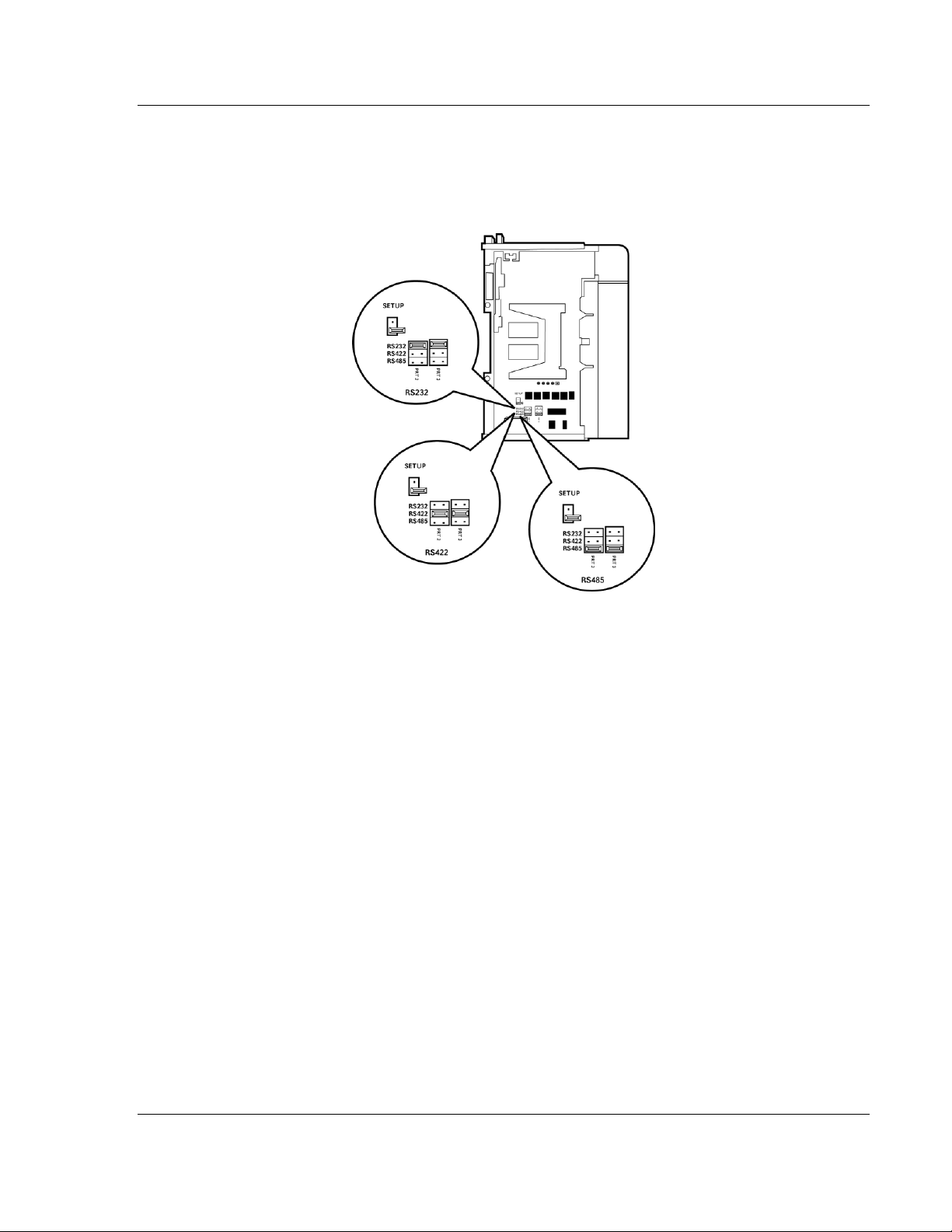
1.4 Setting Jumpers
When the module is manufactured, the port selection jumpers are set to RS-232.
To use RS-422 or RS-485, you must set the jumpers to the correct position. The
following diagram describes the jumper settings.
The Setup Jumper acts as "write protection" for the module’s flash memory. In
"write protected" mode, the Setup pins are not connected, and the module’s
firmware cannot be overwritten. Do not jumper the Setup pins together unless
you are directed to do so by ProSoft Technical Support.
ProSoft Technology, Inc. Page 15 of 167
March 22, 2011
Page 16
Start Here MVI69-MCM ♦ CompactLogix or MicroLogix Platform
User Manual Modbus Communication Module
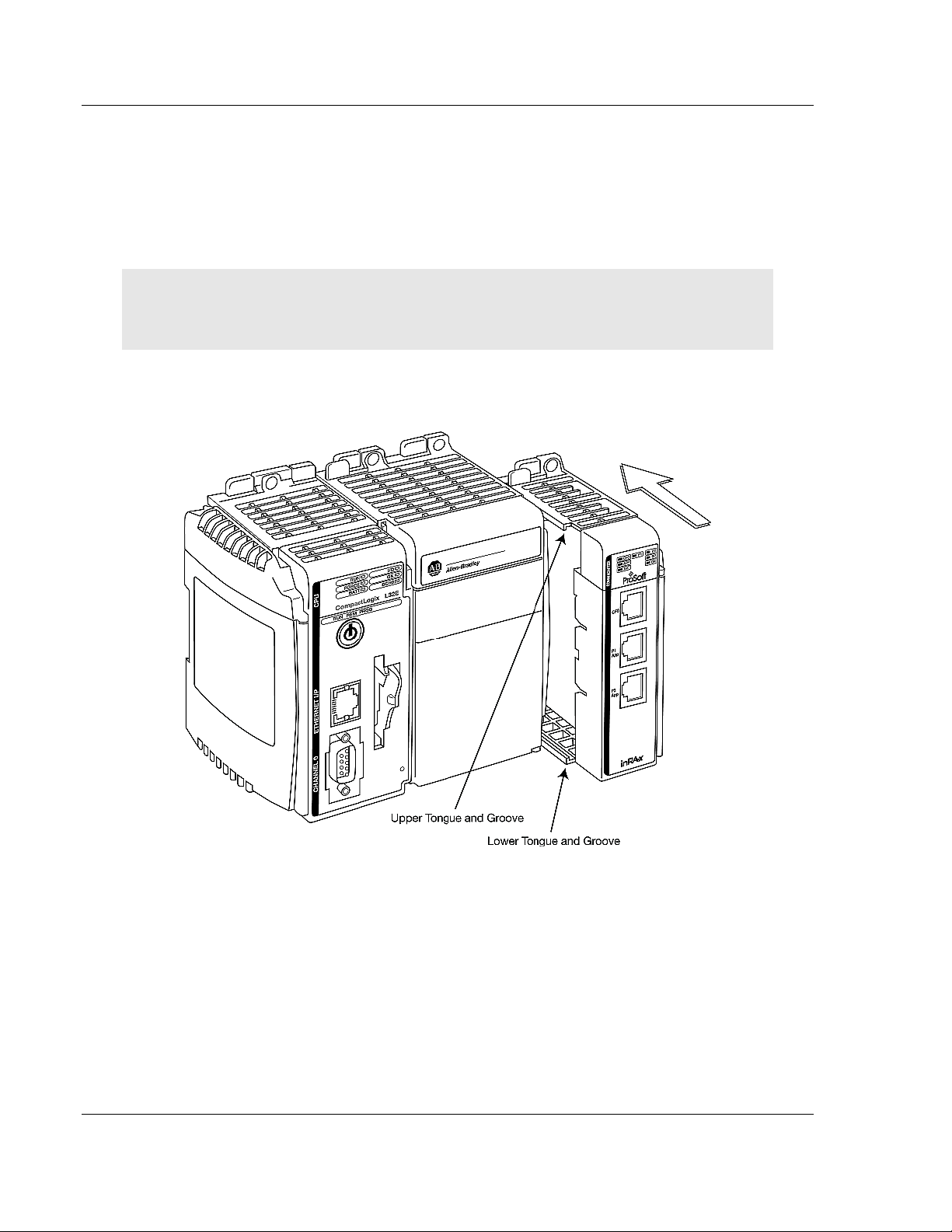
1.5 Install the Module in the Rack
This section describes how to install the module into a CompactLogix or
MicroLogix rack
Before you attempt to install the module, make sure that the bus lever of the
adjacent module is in the unlocked (fully right) position.
Warning: This module is not hot-swappable! Always remove power from the rack before
inserting or removing this module, or damage may result to the module, the processor, or other
connected devices.
1 Align the module using the upper and lower tongue-and-groove slots with the
adjacent module and slide forward in the direction of the arrow.
2 Move the module back along the tongue-and-groove slots until the bus
connectors on the MVI69 module and the adjacent module line up with each
other.
Page 16 of 167 ProSoft Technology, Inc.
March 22, 2011
Page 17
MVI69-MCM ♦ CompactLogix or MicroLogix Platform Start Here
Modbus Communication Module User Manual
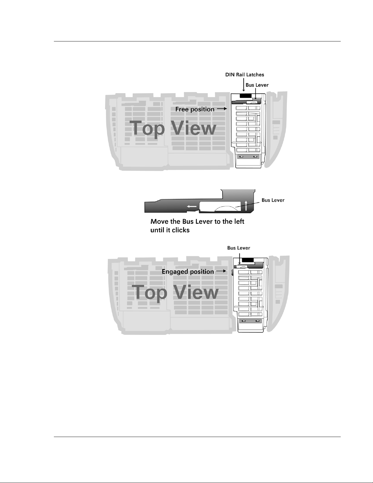
3 Push the module’s bus lever back slightly to clear the positioning tab and
move it firmly to the left until it clicks. Ensure that it is locked firmly in place.
4 Close all DIN-rail latches.
ProSoft Technology, Inc. Page 17 of 167
March 22, 2011
Page 18
Start Here MVI69-MCM ♦ CompactLogix or MicroLogix Platform
User Manual Modbus Communication Module
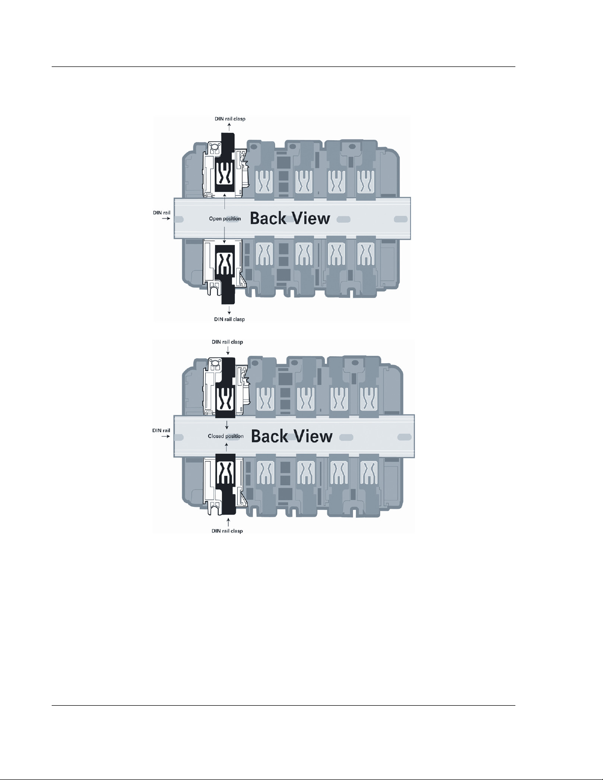
5 Press the DIN-rail mounting area of the controller against the DIN-rail. The
latches will momentarily open and lock into place.
Page 18 of 167 ProSoft Technology, Inc.
March 22, 2011
Page 19

MVI69-MCM ♦ CompactLogix or MicroLogix Platform Configuring the MVI69-MCM Module
Modbus Communication Module User Manual
2 Configuring the MVI69-MCM Module
In This Chapter
MVI69-MCM Sample Add-On Instruction Import Procedure .................. 20
Using ProSoft Configuration Builder ...................................................... 46
Downloading the Project to the Module Using a Serial COM port ......... 49
Module Configuration ............................................................................ 50
ProSoft Technology, Inc. Page 19 of 167
March 22, 2011
Page 20
Configuring the MVI69-MCM Module MVI69-MCM ♦ CompactLogix or MicroLogix Platform
User Manual Modbus Communication Module
2.1 MVI69-MCM Sample Add-On Instruction Import Procedure
Note: this section only applies if you are using RSLogix 5000 version 16 or higher. If you are
configuring the MVI69-MCM module with an earlier version of RSLogix 5000, please refer to
Installing and Configuring the Module with a CompactLogix Processor (page 75).
The following file is required before you start this procedure. Copy the file from
the ProSoft Solutions CD-ROM, or download it from
www.prosoft-technology.com.
File Name Description
MVI69MCM_AddOn_Rung_v1_4.L
5x
L5X file contains the Add-On instruction, the user defined data
types, data objects and ladder logic required to set up the
MVI69-MCM module
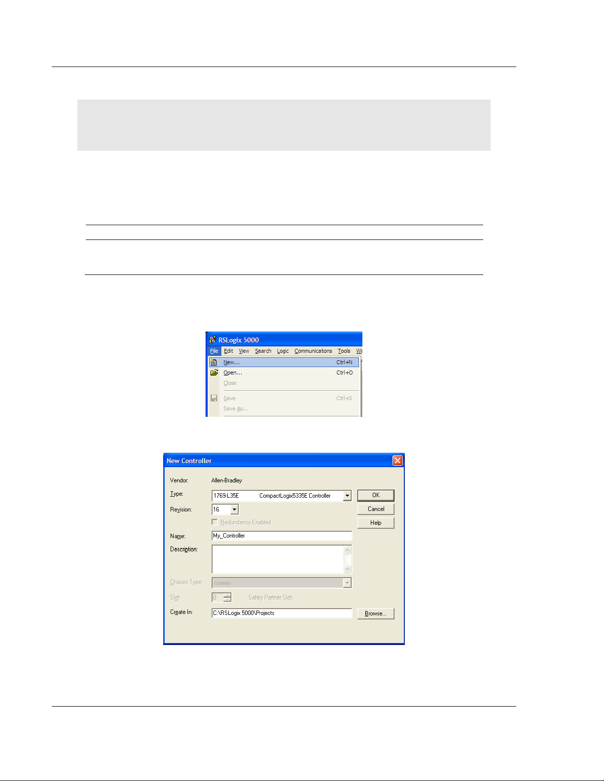
2.1.1 Create a new RSLogix5000 project
1 Open the F
ILE
menu, and then choose NEW…
2 Select R
EVISION
16
Page 20 of 167 ProSoft Technology, Inc.
March 22, 2011
Page 21
MVI69-MCM ♦ CompactLogix or MicroLogix Platform Configuring the MVI69-MCM Module
Modbus Communication Module User Manual
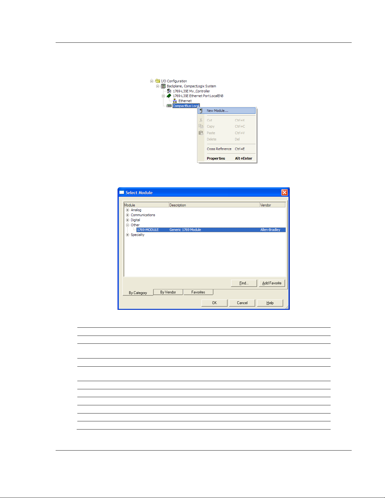
2.1.2 Create the Module
1 Right-click I/O C
ONFIGURATION
2 Select 1769-MODULE
and choose N
EW MODULE
…
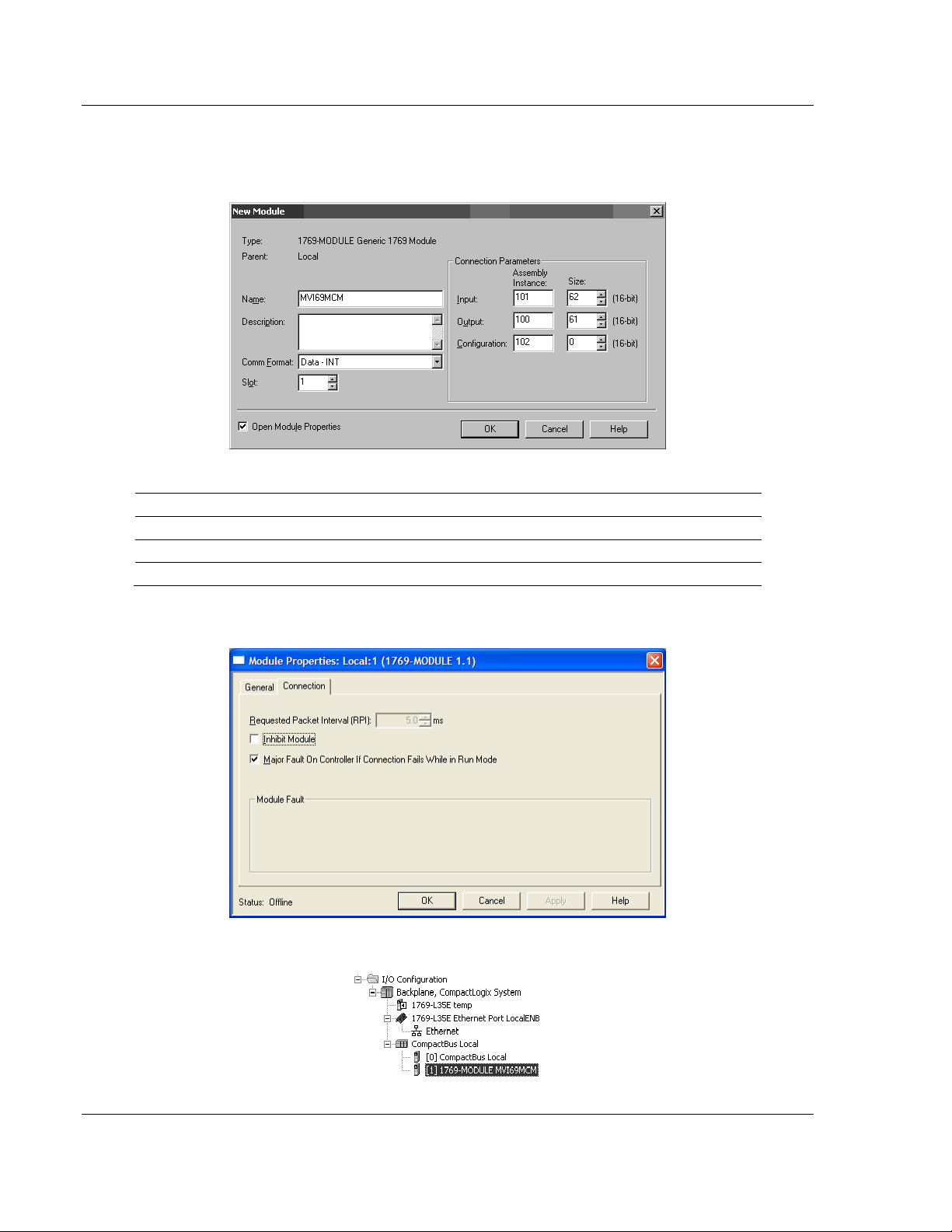
3 Set the Module Properties values as follows:
Parameter Value
Name Enter a module identification string. Example: MVI69MCM
Description Enter a description for the module. Example: ProSoft
communication module for Serial Modbus communications.
Comm Format Select Data-INT
Slot Enter the slot number in the rack where the MV69-MCM
module will be installed.
Input Assembly Instance 101
Input Size 62 / 122 / 242
Output Assembly Instance 100
Output Size 61 / 121 / 241
Configuration Assembly Instance 102
Configuration Size 0
ProSoft Technology, Inc. Page 21 of 167
March 22, 2011
Page 22
Configuring the MVI69-MCM Module MVI69-MCM ♦ CompactLogix or MicroLogix Platform
User Manual Modbus Communication Module
The following illustration shows an example where the module was
configured for a block transfer size of 60 words (input block size = 62 words,
output block size = 61 words):
The following options are available:
Block Transfer Size Input Block Size Output Block Size
60 62 61
120 122 121
240 242 241
4 On the Connection tab, set the RPI value for your project. Click OK to
confirm.
Now the MVI69-MCM module will be visible at the I/O Configuration section.
Page 22 of 167 ProSoft Technology, Inc.
March 22, 2011
Page 23
MVI69-MCM ♦ CompactLogix or MicroLogix Platform Configuring the MVI69-MCM Module
Modbus Communication Module User Manual
2.1.3 Import the Ladder Rung
1 Open your application in RSLogix 5000.
2 To create a new routine, expand the T
T
ASK
folder.
3 On the M
AIN PROGRAM
folder, click the right mouse button to open a shortcut
menu. On the shortcut menu, choose N
4 In the N
EW ROUTINE
dialog box, enter the name and description of your
routine, and then click OK. In this example we are demonstrating the
importing of the ladder rung using the default MainRoutine. In the case where
you create a routine by an other name for placing the Add-On instruction,
then in your original routine where your other ladder logic is located you need
to add a rung with a jump instruction to the new routine holding the Add-On
instruction.
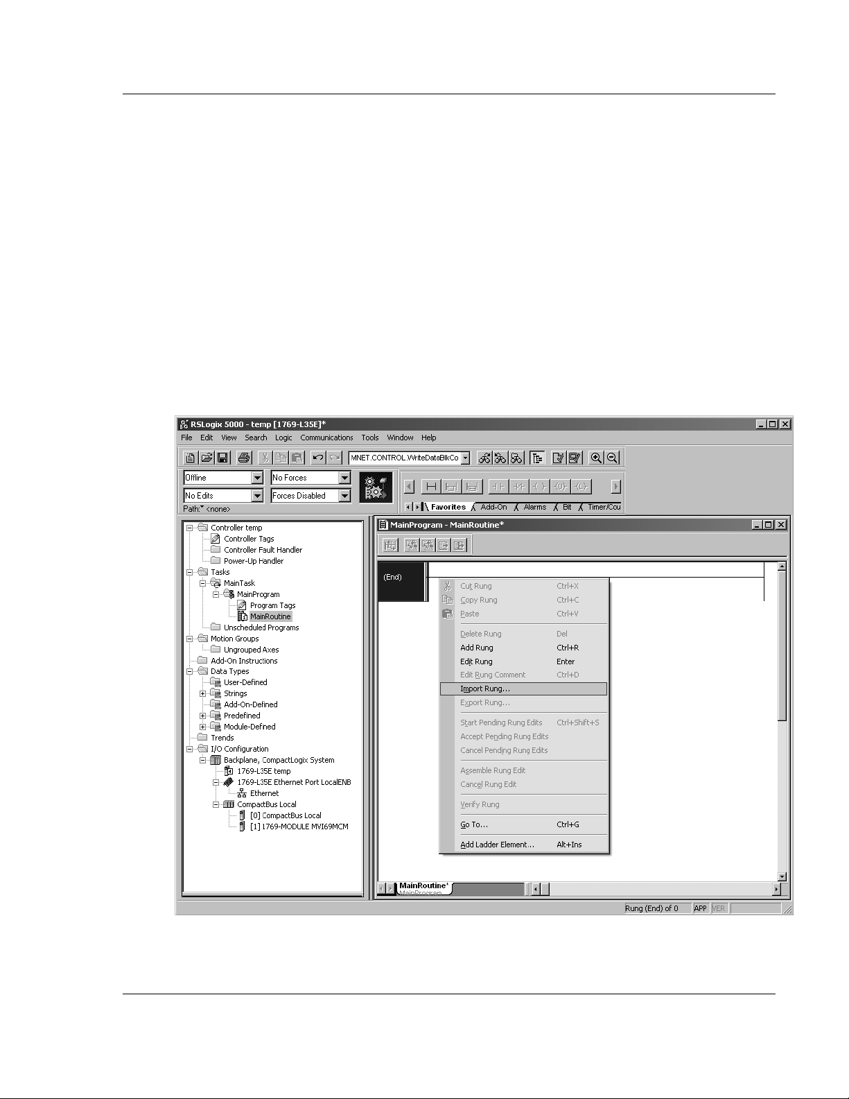
5 Select an empty rung in the new routine, and then click the right mouse
button to open a shortcut menu. On the shortcut menu, choose "I
R
UNG
…".
ASKS
folder, and then expand the M
EW ROUTINE
.
AIN
MPORT
ProSoft Technology, Inc. Page 23 of 167
March 22, 2011
Page 24
Configuring the MVI69-MCM Module MVI69-MCM ♦ CompactLogix or MicroLogix Platform
User Manual Modbus Communication Module
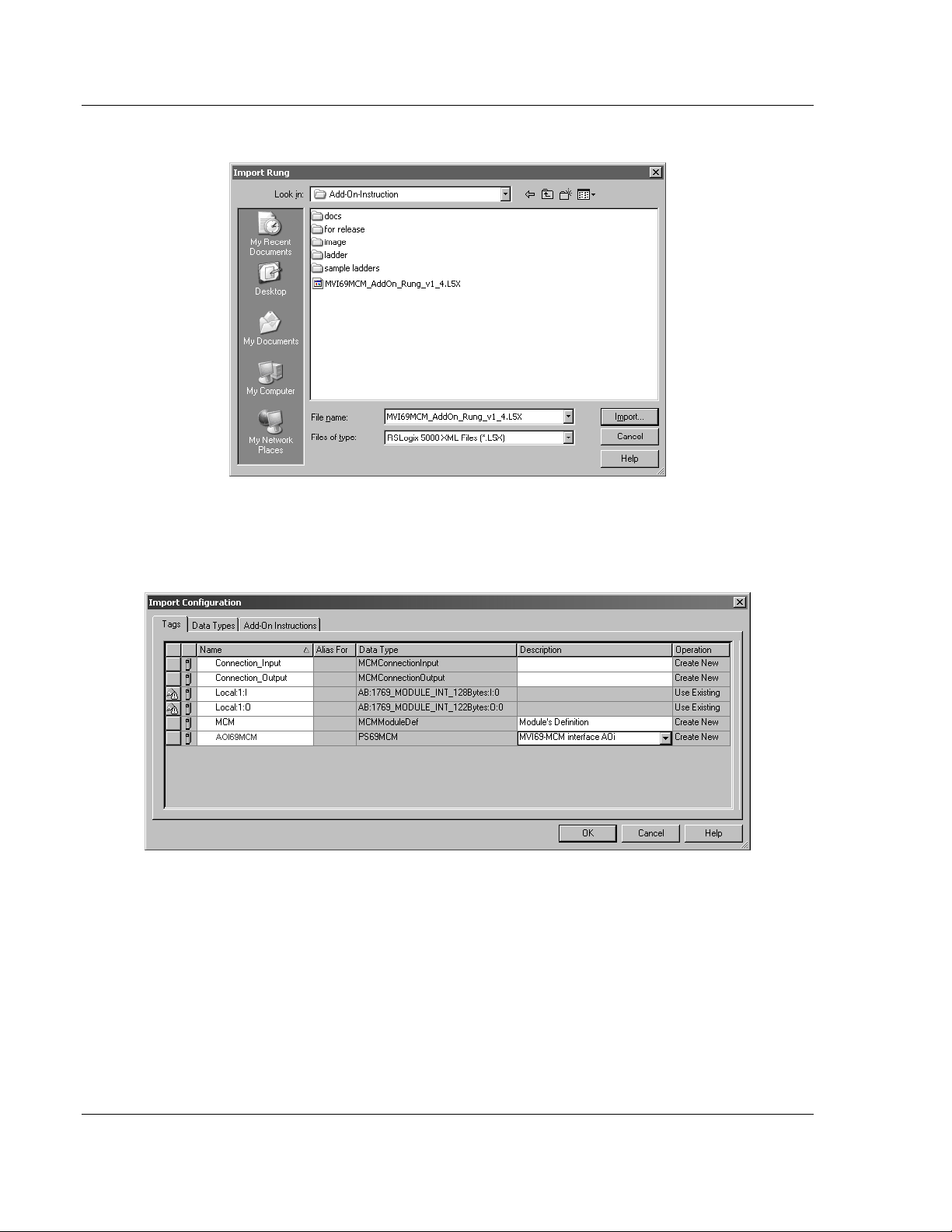
6 Select the MVI69MCM_ADDON_R
UNG_V
1_4.L5X file
7 The following window will be displayed showing the controller tags to be
created during the import procedure: If desired, the description, "MVI69-MCM
Interface AOI" may be typed into the description field for
MVI69MCM_AddOn_Rung_v1_4.L5x file.
Page 24 of 167 ProSoft Technology, Inc.
March 22, 2011
Page 25
MVI69-MCM ♦ CompactLogix or MicroLogix Platform Configuring the MVI69-MCM Module
Modbus Communication Module User Manual
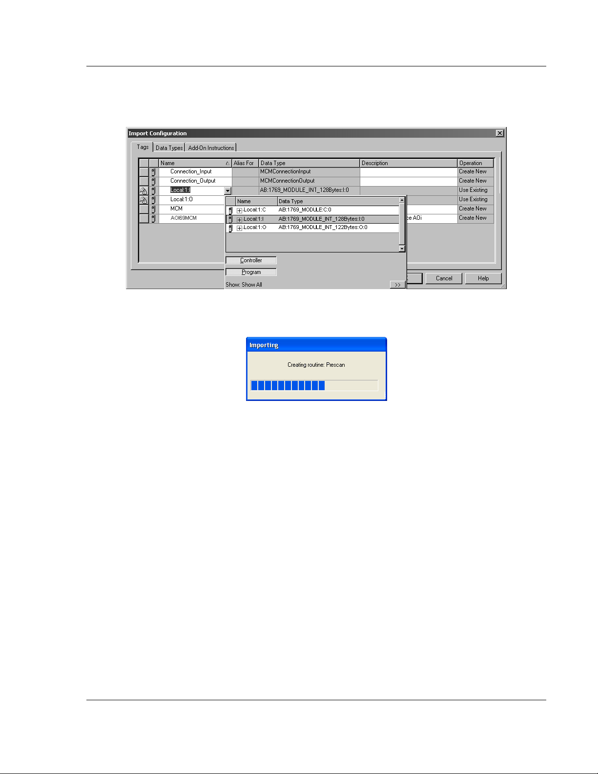
8 If you are using the module in a different slot (or remote rack) select the
correct connection input and output variables associated to the module. If
your module is located in slot 1 of the local rack this step is not required.
9 Click OK to confirm the import. RSLogix will indicate that the import is under
progress:
ProSoft Technology, Inc. Page 25 of 167
March 22, 2011
Page 26
Configuring the MVI69-MCM Module MVI69-MCM ♦ CompactLogix or MicroLogix Platform
User Manual Modbus Communication Module
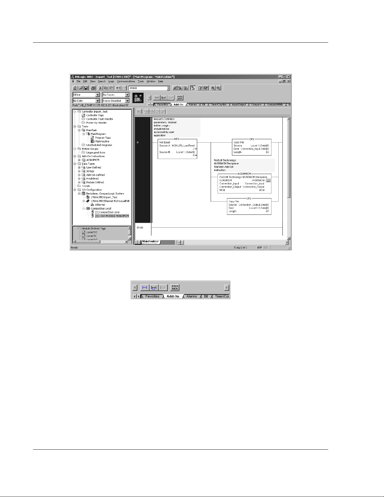
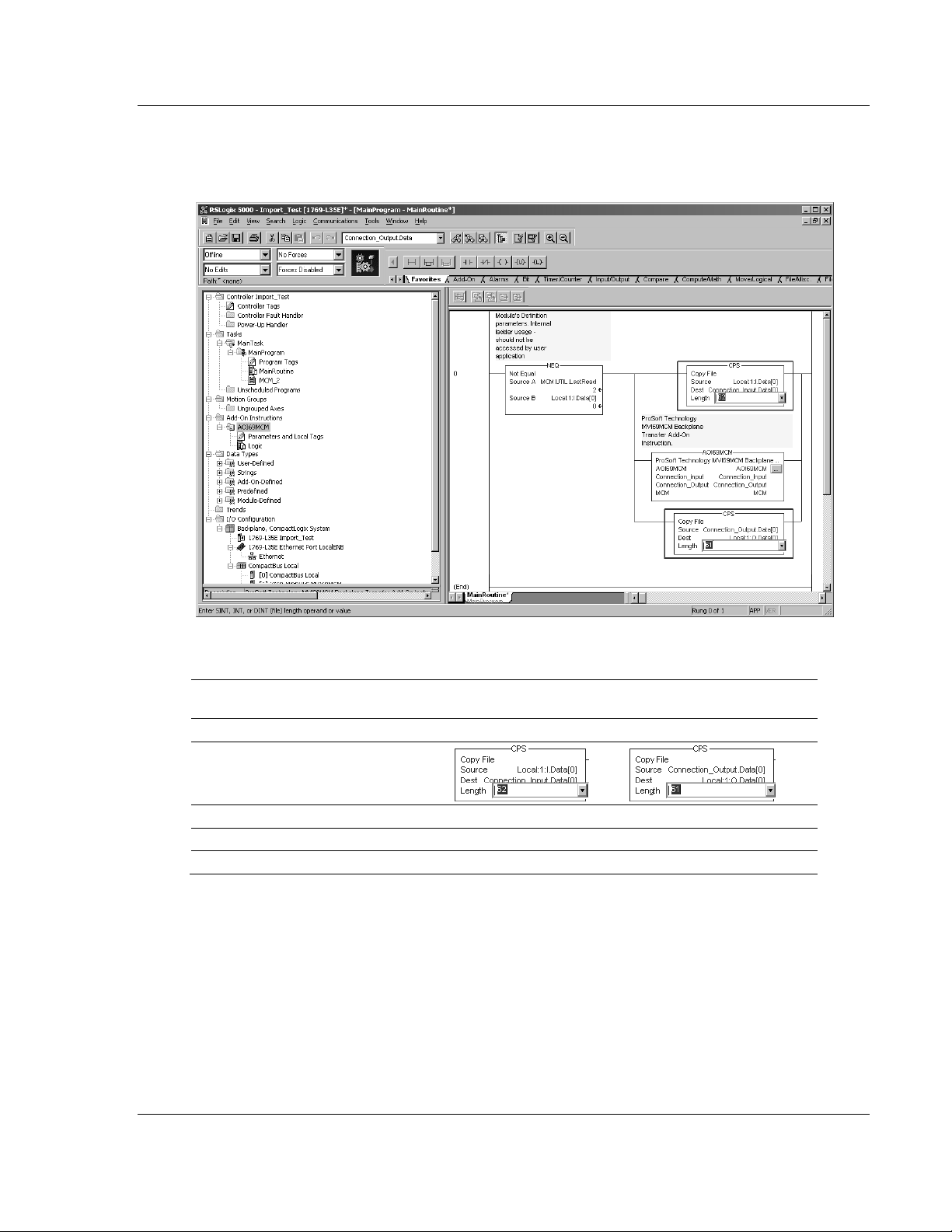
When the import is completed, the new rung with the Add-On instruction will
be visible as shown in the following illustration.
The procedure has also imported new user defined data types, data objects
and the Add-On instruction to be used at your project.
Page 26 of 167 ProSoft Technology, Inc.
March 22, 2011
Page 27
MVI69-MCM ♦ CompactLogix or MicroLogix Platform Configuring the MVI69-MCM Module
Modbus Communication Module User Manual
10 The imported rung will contain the Add-On instruction with two CPS
instructions as follows below. The CPS instructions are set by default for a
length of 62/61 words as follows:
Edit the above CPS instructions Length field values according to the following
table.
"Block Transfer Size Parameter" –
60/120/240 options)
Connection Parameters: CPS instructions Length field values:
Input Size: Output Size:
62 61 62 61
122 121 122 121
242 241 242 241
Ladder Routine window:
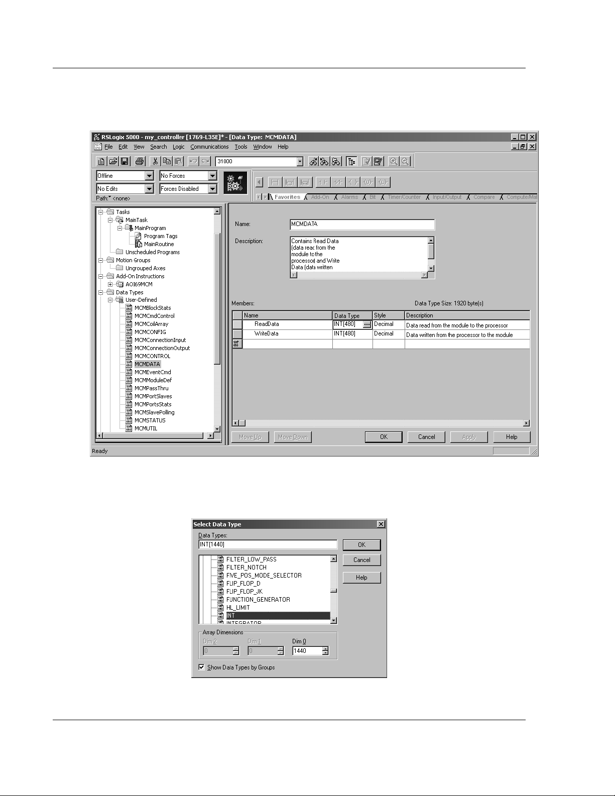
2.1.4 Set the Read/Write Data Lengths
1 The imported rung contains the MCMDATA object Tag arrays R
W
RITEDATA
o READDATA
o
W
RITEDATA
set to the factory default values of 480. These tags will contain:
- data area copied from the module to the processor
- data area copied from the processor to the module
EADDATA
and
ProSoft Technology, Inc. Page 27 of 167
March 22, 2011
Page 28
Configuring the MVI69-MCM Module MVI69-MCM ♦ CompactLogix or MicroLogix Platform
User Manual Modbus Communication Module
2 If you have changed the R
values in the [B
ACKPLANE
EAD REGISTER COUNT
and W
RITE REGISTER COUNT
69] section of the module’s configuration file, you
must adjust these array sizes to match those values.
Example: If in the configuration file section [Backplane 69] the parameter
setting is "Read Register Count : 1440" then set ReadData tag array size to
INT[1440].
Page 28 of 167 ProSoft Technology, Inc.
March 22, 2011
Page 29
MVI69-MCM ♦ CompactLogix or MicroLogix Platform Configuring the MVI69-MCM Module
Modbus Communication Module User Manual
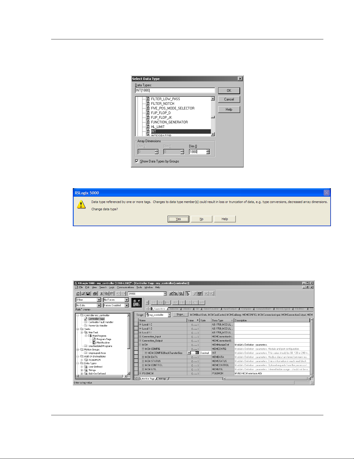
Example: If in the configuration file section [Backplane 69] the parameter
setting is "Write Register Count : 1880" then set WriteData tag array size to
INT[1880].
You will be prompted to confirm the changes. Click Yes to continue.
2.1.5 Set the Block Transfer Parameter Size
The MCM.B
Instruction. If you have configured a different block transfer size in the module’s
configuration file, you must change this value to match.
LOCKTRANSFERSIZE
controller tag is set to 60 in the Add-On
Edit the tag values according to the following table.
ProSoft Technology, Inc. Page 29 of 167
March 22, 2011
Page 30
Configuring the MVI69-MCM Module MVI69-MCM ♦ CompactLogix or MicroLogix Platform
User Manual Modbus Communication Module
Module Properties dialog box: Controller Organizer’s Controller Tags folder:
Connection Parameters: MCM.BlockTransferSize tag value:
Input Size: Output Size:
62 61 60
122 121 120
242 241 240
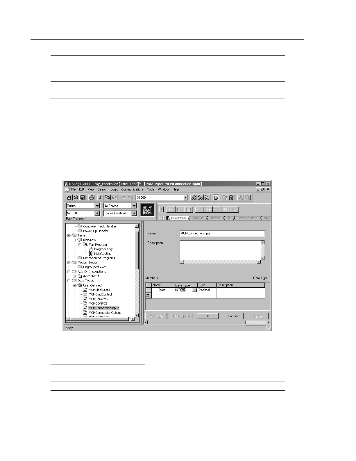
2.1.6 Set the Connection Input Size Values
If you change the block transfer size, you must also change the following data
types:
MCMC
Add-On instruction.
MCMC
the Add-On instruction.
Access the user data type definition MCMC
ONNECTIONINPUT
ONNECTIONOUTPUT
– Data type used for the Connection Input pin in the
– Data type used for the Connection Output pin in
ONNECTIONINPUT
as follows
Edit the tag values according to the following table.
Module Properties dialog box: Controller Organizer’s Controller Tags folder:
Connection Parameters: MCMConnectionInput.Data tag value:
Input Size:
62 62
122 122
242 242
Page 30 of 167 ProSoft Technology, Inc.
March 22, 2011
Page 31

MVI69-MCM ♦ CompactLogix or MicroLogix Platform Configuring the MVI69-MCM Module
Modbus Communication Module User Manual
Access the user data type definition MCMC
ONNECTIONOUTPUT
as follows:
Edit the tag values according to the following table.
Module Properties dialog box: Controller Organizer’s Controller Tags folder:
Connection Parameters: MCMConnectionOutput.Data tag value:
Output Size:
61 61
121 121
241 241
2.1.7 Adding Multiple Modules (Optional)
Important: If your application requires more than one MVI69-MCM module into the same project,
follow the steps below and make certain that both modules are assigned identical Block Transfer
Sizes.
ProSoft Technology, Inc. Page 31 of 167
March 22, 2011
Page 32

Configuring the MVI69-MCM Module MVI69-MCM ♦ CompactLogix or MicroLogix Platform
User Manual Modbus Communication Module
1 In the I/O C
ONFIGURATION
folder, click the right mouse button to open a
shortcut menu, and then choose New Module.
2 Select 1769-MODULE
3 Fill the module properties as follows:
Parameter Value
Name Enter a module identification string. Example:
MVI69MCM_2
Description Enter a description for the module. Example: ProSoft
communication module for Serial Modbus communications.
Comm Format Select Data-INT
Slot Enter the slot number in the rack where the MV69-MCM
module will be installed.
Input Assembly Instance 101
Input Size 62 / 122 / 242
Output Assembly Instance 100
Output Size 61 / 121 / 241
Configuration Assembly Instance 102
Configuration Size 0
Page 32 of 167 ProSoft Technology, Inc.
March 22, 2011
Page 33

MVI69-MCM ♦ CompactLogix or MicroLogix Platform Configuring the MVI69-MCM Module
Modbus Communication Module User Manual
4 Click OK to confirm. The new module is now visible:
5 Expand the T
6 On the M
menu. On the shortcut menu, choose N
ASKS
folder, and then expand the M
AINPROGRAM
AINTASK
folder.
folder, click the right mouse button to open a shortcut
EW ROUTINE
.
7 In the New Routine dialog box, enter the name and description of your
routine, and then click OK.
8 Select an empty rung in the new routine, and then click the right mouse
button to open a shortcut menu. On the shortcut menu, choose "I
R
UNG
…".
MPORT
Note: It is not necessary to create a completely new routine. It is possible to add the MVI69MCM_2 module in the previously created routine. If it is desired to create a new routine the user
needs to also create a rung with a jump instruction in the previous routine to the new routine.
ProSoft Technology, Inc. Page 33 of 167
March 22, 2011
Page 34

Configuring the MVI69-MCM Module MVI69-MCM ♦ CompactLogix or MicroLogix Platform
User Manual Modbus Communication Module
9 Select the file MVI69MCM_ADDON_R
UNG_V
1_4.L5X
10 The following window will be displayed showing the tags to be imported:
Page 34 of 167 ProSoft Technology, Inc.
March 22, 2011
Page 35

MVI69-MCM ♦ CompactLogix or MicroLogix Platform Configuring the MVI69-MCM Module
Modbus Communication Module User Manual
11 Associate the I/O connection variables to the correct module. The default
values are L
OCAL
:1:I and L
OCAL
:1:O. These require re-assignment to the
new module's location.
ProSoft Technology, Inc. Page 35 of 167
March 22, 2011
Page 36

Configuring the MVI69-MCM Module MVI69-MCM ♦ CompactLogix or MicroLogix Platform
User Manual Modbus Communication Module
12 Change the default tags MCM and AOI69MCM to avoid conflict with existing
tags. This example procedure will append the string "_2" as follows:
13 You will be prompted to confirm your change. Click OK to continue.
Page 36 of 167 ProSoft Technology, Inc.
March 22, 2011
Page 37

MVI69-MCM ♦ CompactLogix or MicroLogix Platform Configuring the MVI69-MCM Module
Modbus Communication Module User Manual
14 Click OK to confirm.
ProSoft Technology, Inc. Page 37 of 167
March 22, 2011
Page 38

Configuring the MVI69-MCM Module MVI69-MCM ♦ CompactLogix or MicroLogix Platform
User Manual Modbus Communication Module
15 Because the second module's logic was created in a new routine, enter a
rung in the Main routine with a JSR instruction to the new routine to enable
the PLC logic to communicate with both modules.
The setup procedure is now complete. Save the project and download the
application to your CompactLogix processor.
Page 38 of 167 ProSoft Technology, Inc.
March 22, 2011
Page 39

MVI69-MCM ♦ CompactLogix or MicroLogix Platform Configuring the MVI69-MCM Module
Modbus Communication Module User Manual
2.1.8 Connecting Your PC to the Processor
1 Connect the right-angle connector end of the cable to your controller at the
communications port.
2 Connect the straight connector end of the cable to the serial port on your
computer.
2.1.9 Download the Sample Program to the Processor
Configuring the RSLinx Driver for the PC COM Port
If RSLogix is unable to establish communication with the processor, follow these
steps.
1 Open RSLinx.
ProSoft Technology, Inc. Page 39 of 167
March 22, 2011
Page 40

Configuring the MVI69-MCM Module MVI69-MCM ♦ CompactLogix or MicroLogix Platform
User Manual Modbus Communication Module
2 Open the C
OMMUNICATIONS
menu, and choose C
ONFIGURE DRIVERS
.
This action opens the Configure Drivers dialog box.
Note: If the list of configured drivers is blank, you must first choose and configure a driver from the
Available Driver Types list. The recommended driver type to choose for serial communication with
the processor is RS-232 DF1 Devices.
Page 40 of 167 ProSoft Technology, Inc.
March 22, 2011
Page 41

MVI69-MCM ♦ CompactLogix or MicroLogix Platform Configuring the MVI69-MCM Module
Modbus Communication Module User Manual
1 Click to select the driver, and then click C
ONFIGURE
. This action opens the
Configure RS-232 DF1 Devices dialog box.
2 Click the A
UTO-CONFIGURE
button. RSLinx will attempt to configure your
serial port to work with the selected driver.
3 When you see the message Auto Configuration Successful, click the OK
button to dismiss the dialog box.
Note: If the auto-configuration procedure fails, verify that the cables are connected correctly
between the processor and the serial port on your computer, and then try again. If you are still
unable to auto-configure the port, refer to your RSLinx documentation for further troubleshooting
steps.
Downloading to the Processor
Note: The key switch on the front of the CompactLogix processor must be in the REM
OR
PROG
position.
1 If you are not already online to the processor, open the C
menu, and then choose D
OWNLOAD.
RSLogix will establish communication
OMMUNICATIONS
with the processor.
ProSoft Technology, Inc. Page 41 of 167
March 22, 2011
Page 42

Configuring the MVI69-MCM Module MVI69-MCM ♦ CompactLogix or MicroLogix Platform
User Manual Modbus Communication Module
2 When communication is established, RSLogix will open a confirmation dialog
box. Click the D
OWNLOAD
button to transfer the sample program to the
processor.
3 RSLogix will compile the program and transfer it to the processor. This
process may take a few minutes.
4 When the download is complete, RSLogix will open another confirmation
dialog box. Click OK to switch the processor from P
ROGRAM
mode to R
UN
mode.
Note: If you receive an error message during these steps, refer to your RSLogix documentation to
interpret and correct the error.
Page 42 of 167 ProSoft Technology, Inc.
March 22, 2011
Page 43

MVI69-MCM ♦ CompactLogix or MicroLogix Platform Configuring the MVI69-MCM Module
Modbus Communication Module User Manual
Disabling the RSLinx Driver for the Com Port on the PC
The communication port driver in RSLinx can occasionally prevent other
applications from using the PC’s COM port. If you are not able to connect to the
module’s configuration/debug port using ProSoft Configuration Builder (PCB),
HyperTerminal or another terminal emulator, follow these steps to disable the
RSLinx Driver.
1 Open RSLinx and go to C
OMMUNICATIONS
>RSWHO
2 Make sure that you are not actively browsing using the driver that you wish to
stop. The following shows an actively browsed network:
3 Notice how the DF1 driver is opened, and the driver is looking for a processor
on node 1. If the network is being browsed, then you will not be able to stop
this driver. To stop the driver your RSWho screen should look like this:
Branches are displayed or hidden by clicking on the or the icons.
4 When you have verified that the driver is not being browsed, go to
C
OMMUNICATIONS>CONFIGURE DRIVERS
ProSoft Technology, Inc. Page 43 of 167
March 22, 2011
Page 44

Configuring the MVI69-MCM Module MVI69-MCM ♦ CompactLogix or MicroLogix Platform
User Manual Modbus Communication Module
You may see something like this:
If you see the status as running, you will not be able to use this com port for
anything other than communication to the processor. To stop the driver press
the S
TOP
button on the side of the window:
5 After you have stopped the driver you will see the following:
6 You may now use the com port to connect to the debug port of the module.
Note: You may need to shut down and restart your PC before it will allow you to stop the driver
(usually only on Windows NT machines). If you have followed all of the above steps, and it will not
stop the driver, then make sure you do not have RSLogix open. If RSLogix is not open, and you
still cannot stop the driver, then reboot your PC.
Page 44 of 167 ProSoft Technology, Inc.
March 22, 2011
Page 45

MVI69-MCM ♦ CompactLogix or MicroLogix Platform Configuring the MVI69-MCM Module
Modbus Communication Module User Manual
2.1.10 Connect your PC to the Module
With the module securely mounted, connect your PC to the Configuration/Debug
port using an RJ45-DB-9 Serial Adapter Cable and a Null Modem Cable.
1 Attach both cables as shown.
2 Insert the RJ45 cable connector into the Configuration/Debug port of the
module.
3 Attach the other end to the serial port on your PC.
ProSoft Technology, Inc. Page 45 of 167
March 22, 2011
Page 46

Configuring the MVI69-MCM Module MVI69-MCM ♦ CompactLogix or MicroLogix Platform
User Manual Modbus Communication Module
2.2 Using ProSoft Configuration Builder
ProSoft Configuration Builder (PCB) provides a quick and easy way to manage
module configuration files customized to meet your application needs. PCB is not
only a powerful solution for new configuration files, but also allows you to import
information from previously installed (known working) configurations to new
projects.
2.2.1 Setting Up the Project
To begin, start ProSoft Configuration Builder. If you have used other Windows
configuration tools before, you will find the screen layout familiar. ProSoft
Configuration Builder’s window consists of a tree view on the left, an information
pane and a configuration pane on the right side of the window. When you first
start ProSoft Configuration Builder, the tree view consists of folders for Default
Project and Default Location, with a Default Module in the Default Location
folder. The following illustration shows the ProSoft Configuration Builder window
with a new project.
Your first task is to add the MVI69-MCM module to the project.
1 Use the mouse to select D
EFAULT MODULE
in the tree view, and then click the
right mouse button to open a shortcut menu.
Page 46 of 167 ProSoft Technology, Inc.
March 22, 2011
Page 47

MVI69-MCM ♦ CompactLogix or MicroLogix Platform Configuring the MVI69-MCM Module
Modbus Communication Module User Manual
2 On the shortcut menu, select C
HOOSE MODULE TYPE
. This action opens the
Choose Module Type dialog box.
3 In the Product Line Filter area of the dialog box, select MVI69. In the Select
Module Type dropdown list, select MVI69-MCM, and then click OK to save
your settings and return to the ProSoft Configuration Builder window.
ProSoft Technology, Inc. Page 47 of 167
March 22, 2011
Page 48

Configuring the MVI69-MCM Module MVI69-MCM ♦ CompactLogix or MicroLogix Platform
User Manual Modbus Communication Module
2.2.2 Renaming PCB Objects
Notice that the contents of the information pane and the configuration pane
changed when you added the module to the project.
At this time, you may wish to rename the Default Project and Default Location
folders in the tree view.
1 Select the object, and then click the right mouse button to open a shortcut
menu. From the shortcut menu, choose R
ENAME
.
2 Type the name to assign to the object.
3 Click away from the object to save the new name.
Configuring Module Parameters
1 Click on the [+] sign next to the module icon to expand module information.
2 Click on the [+] sign next to any icon to view module information and
configuration options.
3 Double-click any icon to open an Edit dialog box.
4 To edit a parameter, select the parameter in the left pane and make your
changes in the right pane.
5 Click OK to save your changes.
Printing a Configuration File
1 Select the module icon, and then click the right mouse button to open a
shortcut menu.
2 On the shortcut menu, choose V
IEW CONFIGURATION
. This action opens the
View Configuration window.
3 In the View Configuration window, open the F
ILE
menu, and choose P
RINT.
This action opens the Print dialog box.
4 In the Print dialog box, choose the printer to use from the drop-down list,
select printing options, and then click OK.
Page 48 of 167 ProSoft Technology, Inc.
March 22, 2011
Page 49

MVI69-MCM ♦ CompactLogix or MicroLogix Platform Configuring the MVI69-MCM Module
Modbus Communication Module User Manual
2.3 Downloading the Project to the Module Using a Serial COM port
For the module to use the settings you configured, you must download (copy) the
updated Project file from your PC to the module.
1 In the tree view in ProSoft Configuration Builder, click once to select the
module.
2 Open the Project menu, and then choose M
will scan your PC for a valid com port (this may take a few seconds). When
PCB has found a valid COM port, the Download dialog box will open.
ODULE/DOWNLOAD
. The program
3 Choose the COM port to use from the dropdown list, and then click the
D
OWNLOAD
button.
The module will perform a platform check to read and load its new settings.
When the platform check is complete, the status bar in the Download dialog
box will display the message Module Running.
ProSoft Technology, Inc. Page 49 of 167
March 22, 2011
Page 50

Configuring the MVI69-MCM Module MVI69-MCM ♦ CompactLogix or MicroLogix Platform
User Manual Modbus Communication Module
2.4 Module Configuration
2.4.1 [Module]
This section defines the configuration for the Module level data.
Module Name
0 to 80 characters
This parameter assigns a name to the module that can be viewed using the
configuration/debug port. Use this parameter to identify the module and the
configuration file.
2.4.2 [Backplane 69]
This section provides the module with a unique name, identifies the method of
failure for the communications for the module if the processor is not in run, and
describes how to initialize the module upon startup.
The following example shows a sample [Backplane Configuration] section:
Modify each of the parameters based on the needs of your application.
Page 50 of 167 ProSoft Technology, Inc.
March 22, 2011
Page 51

MVI69-MCM ♦ CompactLogix or MicroLogix Platform Configuring the MVI69-MCM Module
Modbus Communication Module User Manual
Read Register Start
0 to 4999
The Read Register Start parameter specifies the start of the Read Data area in
module memory. Data in this area will be transferred from the module to the
processor.
Note: Total user database memory space is limited to the first 5000 registers of module memory,
addresses 0 through 4999. Therefore, the practical limit for this parameter is 4999 minus the value
entered for Read Register Count, so that the Read Data Area does not try to extend above address
4999. Read Data and Write Data Areas must be configured to occupy separate address ranges in
module memory and should not be allowed to overlap.
Read Register Count
0 to 5000
The Read Register Count parameter specifies the size of the Read Data area of
module memory and the number of registers to transfer from this area to the
processor, up to a maximum of 5000 words.
Note: Total Read Register Count and Write Register Count cannot exceed 5000 total registers.
Read Data and Write Data Areas must be configured to occupy separate address ranges in
module memory and should not be allowed to overlap.
Write Register Start
0 to 4999
The Write Register Start parameter specifies the start of the Write Data area in
module memory. Data in this area will be transferred in from the processor.
Note: Total user database memory space is limited to the first 5000 registers of module memory,
addresses 0 through 4999. Therefore, the practical limit for this parameter is 4999 minus the value
entered for Write Register Count, so that the Write Data Area does not try to extend above address
4999. Read Data and Write Data Areas must be configured to occupy separate address ranges in
module memory and should not be allowed to overlap.
ProSoft Technology, Inc. Page 51 of 167
March 22, 2011
Page 52

Configuring the MVI69-MCM Module MVI69-MCM ♦ CompactLogix or MicroLogix Platform
User Manual Modbus Communication Module
Write Register Count
0 to 5000
The Write Register Count parameter specifies the size of the Write Data area of
module memory and the number of registers to transfer from the processor to
this memory area, up to a maximum value of 5000 words.
Note: Total Read Register Count and Write Register Count cannot exceed 5000 total registers.
Read Data and Write Data Areas must be configured to occupy separate address ranges in
module memory and should not be allowed to overlap.
Backplane Fail Count
0 to 65535
This parameter specifies the number of consecutive backplane transfer failures
that can occur before communications should be halted.
Error/Status Block Pointer
-1 to 4939
Starting register location in virtual Modbus database for the error/status table. If a
value of -1 is entered, the error/status data will not be placed in the database. All
other valid values determine the starting location of the data. This data area
includes the module version information and all server error/status data. Refer to
Status Data Definition for more information.
Initializing Output Data
YES or NO
This parameter determines if the output data for the module should be initialized
with values from the processor. If the value is set to NO (0), the output data will
be initialized to 0. If the value is set to YES (1), the data will be initialized with
data from the processor. Use of this option requires associated ladder logic to
pass the data from the processor to the module.
Block Transfer Size
60, 120 or 240
This read-only parameter specifies the number of words in each block transferred
between the module and processor.
Page 52 of 167 ProSoft Technology, Inc.
March 22, 2011
Page 53

MVI69-MCM ♦ CompactLogix or MicroLogix Platform Configuring the MVI69-MCM Module
Modbus Communication Module User Manual
2.4.3 [MCM Port x]
The information in this section applies to both Port 1 and Port 2.
Enable
Yes or No
This parameter specifies whether to enable or disable the port. No = Port
Disabled, Yes = Port Enabled.
Type
0=Master, 1=Slave, 2=PT Formatted, 3=PT Formatted Swap
This parameter specifies which device type the port will emulate. Refer to Pass-
Through Control Blocks (page 129) for information on using port types 2 or 3.
ProSoft Technology, Inc. Page 53 of 167
March 22, 2011
Page 54

Configuring the MVI69-MCM Module MVI69-MCM ♦ CompactLogix or MicroLogix Platform
User Manual Modbus Communication Module
Float Flag
YES or NO
This flag specifies how the Slave driver will respond to Function Code 3, 6, and
16 commands (read and write Holding Registers) from a remote Master when it
is moving 32-bit floating-point data.
If the remote Master expects to receive or will send one complete 32-bit floatingpoint value for each count of one (1), then set this parameter to YES. When set to
YES, the Slave driver will return values from two consecutive 16-bit internal
memory registers (32 total bits) for each count in the read command, or receive
32-bits per count from the Master for write commands. Example: Count = 10,
Slave driver will send 20 16-bit registers for 10 total 32-bit floating-point values.
If, however, the remote Master sends a count of two (2) for each 32-bit floatingpoint value it expects to receive or send, or, if you do not plan to use floatingpoint data in your application, then set this parameter to NO, which is the default
setting.
You will also need to set the Float Start and Float Offset parameters to
appropriate values whenever the Float Flag parameter is set to YES.
Float Start
0 to 32767
This parameter defines the first register of floating-point data. All requests with
register values greater-than or equal to this value will be considered floating-point
data requests. This parameter is only used if the Float Flag is enabled. For
example, if a value of 7000 is entered, all requests for registers 7000 and above
will be considered as floating-point data.
Float Offset
0 to 4999
This parameter defines the start register for floating-point data in the internal
database. This parameter is used only if the Float Flag is enabled. For example,
if the Float Offset value is set to 3000 and the float start parameter is set to 7000,
data requests for register 7000 will use the internal Modbus register 3000.
Protocol
RTU or ASCII
This parameter specifies the Modbus protocol to be used on the port. Valid
protocols are: rtu = Modbus RTU and ascii = Modbus ASCII.
Page 54 of 167 ProSoft Technology, Inc.
March 22, 2011
Page 55

MVI69-MCM ♦ CompactLogix or MicroLogix Platform Configuring the MVI69-MCM Module
Modbus Communication Module User Manual
Baud Rate
This is the baud rate to be used on the port. Enter the baud rate as a value. For
example, to select 19K baud, enter 19200.
Baud Rate Parameter Value Options
110 110
150 150
300 300
600 600
1200 12 or 1200
2400 24 or 2400
4800 48 or 4800
9600 96 or 9600
19,200 19, 192 or 19200
38,400 38, 384 or 38400
57,600 57 or 576
115,200 115 or 1152
Parity
None, Odd, Even
Parity is a simple error checking algorithm used in serial communication. This
parameter specifies the type of parity checking to use.
All devices communicating through this port must use the same parity setting.
Data Bits
7 or 8
This parameter sets the number of data bits for each word used by the protocol.
All devices communicating through this port must use the same number of data
bits.
Stop Bits
1 or 2
Stop bits signal the end of a character in the data stream. For most applications,
use one stop bit. For slower devices that require more time to re-synchronize,
use two stop bits.
All devices communicating through this port must use the same number of stop
bits.
RTS On
0 to 65535 milliseconds
This parameter sets the number of milliseconds to delay after Ready To Send
(RTS) is asserted before data will be transmitted.
ProSoft Technology, Inc. Page 55 of 167
March 22, 2011
Page 56

Configuring the MVI69-MCM Module MVI69-MCM ♦ CompactLogix or MicroLogix Platform
User Manual Modbus Communication Module
RTS Off
0 to 65535 milliseconds
This parameter sets the number of milliseconds to delay after the last byte of
data is sent before the RTS modem signal will be set low.
Minimum Response Delay
0 to 65535
This parameter is used only when the port is configured as a slave. It sets the
number of milliseconds to wait before responding to a command received on the
port from a remote Master. This delay is sometimes required to accommodate
slower Master devices.
Use CTS Line
YES or NO
This parameter specifies if the Clear To Send (CTS) modem control line is to be
used or not. If the parameter is set to NO, the CTS line will not be monitored. If
the parameter is set to YES, the CTS line will be monitored and must be high
before the module will send data. Normally, this parameter is required when halfduplex modems are used for communication (2-wire). This procedure is
commonly referred to as hardware handshaking.
Slave Address
1 to 255
This parameter defines the Slave Node Address for the internal database. All
requests received by the port with this address are processed by the module.
Verify that each device has a unique address on a network. Valid range for this
parameter is 1 to 255.
Bit Input Offset
0 to 4999
This parameter specifies the offset address into the internal Modbus database for
network requests for Modbus function 2 commands. For example, if the value is
set to 150, an address request of 0 will return the value at register 150 in the
database.
Word Input Offset
0 to 4999
This parameter specifies the offset address into the internal Modbus database for
network requests for Modbus function 4 commands. For example, if the value is
set to 150, an address request of 0 will return the value at register 150 in the
database.
Page 56 of 167 ProSoft Technology, Inc.
March 22, 2011
Page 57

MVI69-MCM ♦ CompactLogix or MicroLogix Platform Configuring the MVI69-MCM Module
Modbus Communication Module User Manual
Output Offset
0 to 4999
This parameter specifies the offset address into the internal Modbus database for
network requests for Modbus function 1, 5 or 15 commands. For example, if the
value is set to 100, an address request of 0 will correspond to register 100 in the
database.
Hold Offset
0 to 4999
This parameter specifies the offset address in the internal Modbus database for
network requests for Modbus function 3, 6, or 16 commands. For example, if a
value of 50 is entered, a request for address 0 will correspond to the register 50
in the database.
Command Count
0 to 100
This parameter specifies the number of commands to be processed by the
Modbus Master port.
Minimum Command Delay
0 to 65535
This parameter specifies the number of milliseconds to wait between issuing
each command. This delay value is not applied to retries.
Command Error Pointer
-1 to 4899
This parameter sets the address in the internal Modbus database where the
command error will be placed. If the value is set to -1, the data will not be
transferred to the database. The valid range of values for this parameter is -1 to
4899. For example, if this parameter is configured for 1000, the command errors
will be copied to the database as follows:
1000: error code for command 0
1001: error code for command 1
and so on.
An error code of 0 means that the command was successfully sent (no error).
Refer to Status Data Definition for the command error code listings.
ProSoft Technology, Inc. Page 57 of 167
March 22, 2011
Page 58

Configuring the MVI69-MCM Module MVI69-MCM ♦ CompactLogix or MicroLogix Platform
User Manual Modbus Communication Module
Response Timeout
0
TO
65535 milliseconds
This parameter sets the command response timeout period in 1 millisecond
increments. This is the time that a port configured as a Master will wait for a
response from the addressed slave before re-transmitting the command (Retries)
or skipping to the next command in the Command List. The value to set depends
on the communication network used and the expected response time (plus a little
extra) of the slowest device on the network.
Retry Count
0 to 10
This parameter specifies the number of times a command will be retried if it fails.
Error Delay Counter
0 to 65535
This parameter specifies the number of polls to skip on the slave before trying to
re-establish communications. After the slave fails to respond, the Master will skip
commands to be sent to the slave the number of times entered in this parameter.
Page 58 of 167 ProSoft Technology, Inc.
March 22, 2011
Page 59

MVI69-MCM ♦ CompactLogix or MicroLogix Platform Configuring the MVI69-MCM Module
Modbus Communication Module User Manual
2.4.4 [Modbus Port x Commands]
The [Modbus Port x Commands] section of the configuration file defines the
command list specifications for the Master port. The information in this section
applies to both Port 1 and Port 2.
Command List Overview
In order to interface the MVI69-MCM module with MODBUS slave devices, you
must construct a command list. The commands in the list specify the slave
device to be addressed, the function to be performed (read or write), the data
area in the device to interface with and the registers in the internal database to
be associated with the device data. The Master command list supports up to 100
commands.
The command list is processed from top (command #0) to bottom. A poll interval
parameter is associated with each command to specify a minimum delay time in
number of seconds between the issuance of a command. If the user specifies a
value of 10 for the parameter, the command will be executed no more frequently
than every 10 seconds.
Write commands have a special feature, as they can be set to execute only if the
data in the write command changes, which can improve network performance. If
the register data values in the command have not changed since the command
was last issued, the command will not be executed. To enable this feature, set
the enable code for the command to a value of 2.
Modbus Command Configuration
The ProSoft Technology MCM Modbus Master and Slave communication drivers
support several data read and write commands. When configuring a Master port,
the decision on which command to use is made depending on the type of data
being addressed, and the level of Modbus support in the slave equipment. When
configuring as a slave, it may be important to understand how the Modbus
commands function in order to determine how to structure the application data.
ProSoft Technology, Inc. Page 59 of 167
March 22, 2011
Page 60

Configuring the MVI69-MCM Module MVI69-MCM ♦ CompactLogix or MicroLogix Platform
User Manual Modbus Communication Module
Floating Point Support
The movement of floating point data between the MCM module and other
devices is easily accomplished as long as the device supports IEEE 754 Floating
Point format. This IEEE format is a 32-bit single precision floating point format.
The programming necessary to move the floating point data takes advantage of
the CPS command that exists in the Compact Logix and SLC processors. The
CPS command is unique for CPX/SLC data movement commands in that it is an
untyped function, meaning that no data conversion is done when moving data
between file types (that is, it is an image copy not a value copy).
The structure of the CPS command to move data from a Floating Point file into
an integer file (something you would do to move floating point values to the
module) is as follows:
This command will move one floating point value in two 16 bit integer images to
the integer file. For multiple floating point values increase the count field by a
factor of 2 per floating point value.
The structure of the COP command to move data from an Integer file to a
Floating Point file (something you would do to receive floating point values from
the module) is as follows:
This command will move two 16 bit integer registers containing one floating point
value image to the floating point file. For multiple values increase the count field.
Page 60 of 167 ProSoft Technology, Inc.
March 22, 2011
Page 61

MVI69-MCM ♦ CompactLogix or MicroLogix Platform Configuring the MVI69-MCM Module
Modbus Communication Module User Manual
ENRON Floating Point Support
Many manufacturers have implemented special support in their drivers to support
what is commonly called the Enron version of the MODBUS protocol. In this
implementation, register addresses > 7000 are presumed to be floating point
values. The significance to this is that the count field now becomes a 'number of
values' field. In floating point format, each value represents two words.
Configuring the Floating Point Data Transfer
A common question when using the module as a Modbus Master is how floating
point data is handled. This really depends on the slave device and how it
addresses this application.
Just because your application is reading/writing floating point data, does not
mean that you must configure the Float Flag, Float Start, and Float Offset
parameters within the module.
These parameters are only used to support what is typically referred to as Enron
or Daniel Modbus, where one register address must have 32 bits, or one floating
point value. Below is an example:
Example #1
Modbus Address Data Type Parameter
47101 32 bit REAL TEMP Pump #1
47102 32 bit REAL Pressure Pump #1
47103 32 bit REAL TEMP Pump #2
47104 32 bit REAL Pressure Pump #2
With the module configured as a Master, you only need to enable these
parameters to support a write to this type of addressing (Modbus FC 6 or 16).
If the slave device shows addressing as shown in Example #2, then you need not
do anything with the Float Flag, Float Start parameters, as they use two Modbus
addresses to represent one floating point value:
Example #2
Modbus Address Data Type Parameter
47101 32 bit REAL TEMP Pump #1
47103 32 bit REAL Pressure Pump #1
47105 32 bit REAL TEMP Pump #2
47107 32 bit REAL Pressure Pump #2
Because each 32 bit REAL value is represented by two Modbus Addresses
(example 47101 and 47102 represent TEMP Pump #1), then you need not set
the Float Flag, or Float Start for the module for Modbus FC 6 or 16 commands
being written to the slave.
The next few pages show three specific examples:
ProSoft Technology, Inc. Page 61 of 167
March 22, 2011
Page 62

Configuring the MVI69-MCM Module MVI69-MCM ♦ CompactLogix or MicroLogix Platform
User Manual Modbus Communication Module
Specific Example #1:Master is issuing Modbus command with FC 16 (with Float Flag: Yes)
to transfer Float data to Slave.
(Float specific module parameters)
Float Flag: "Y" tells the Master to consider the data values that need to be sent
to the Slave as floating point data where each data value is composed of 2 words
(4 bytes or 32 bits).
Float Start: Tells the Master that if this address number is <= the address
number in "Addr in Dev" parameter to double the byte count quantity to be
included in the Command FC6 or FC16 to be issued to the Slave. Otherwise the
Master will ignore the "Float Flag: Y" and treat data as composed of 1 word, 2
bytes.
Page 62 of 167 ProSoft Technology, Inc.
March 22, 2011
Page 63

MVI69-MCM ♦ CompactLogix or MicroLogix Platform Configuring the MVI69-MCM Module
Modbus Communication Module User Manual
(Modbus Command parameters)
DB Addr - Tells the Master where in its data memory is the beginning of data to
obtain and write out to the Slave (slave) device.
Reg Count - Tells the Master how many data points to send to the Slave. Two
counts will mean two floating points with Float Flag: Y and the "Addr in Dev" =>
the "Float Start" Parameter.
Swap Code - Tells the Master how to orient the Byte and Word structure of the
data value. This is device dependent. Check Command Entry formats Section.
Func Code - Tells the Master to write the float values to the Slave. FC16.
Addr in Dev - Tells the Master where in the Slave's database to locate the data.
In the above example, the Master's Modbus command to transmit inside the
Modbus packet will be as follows.
Slave
address
DEC 01 16 7100 2 8 85.37 22.86
HEX 01 10 1B BC 00 02 08 BD 71 42 AA E1 48 41 B6
Function
Code
Address in
Device
Reg count Byte Count Data
In this example, the Master's Modbus packet contains the data byte and data
word counts that have been doubled from the amount specified by Reg Count
due to the Float flag set to Y. Some Slaves look for the byte count in the data
packet to know the length of the data to read from the wire. Other slaves know at
which byte the data begins and read from the wire the remaining bytes in the
packet as the data the Master is sending.
Specific Example#2: Master is issuing Modbus command with FC 16 (with Float Flag: No) to
transfer Float data.
ProSoft Technology, Inc. Page 63 of 167
March 22, 2011
Page 64

Configuring the MVI69-MCM Module MVI69-MCM ♦ CompactLogix or MicroLogix Platform
User Manual Modbus Communication Module
Float Flag: "N" tells the Master to ignore the floating values and treat each
register data as a data point composed of 1 word, 2 bytes or 16 bits.
Float Start: Ignored.
DB Addr - same as when Float Flag: Y.
Reg Count - Tells the Master how many data points to send to the Slave.
Swap Code - same as when Float Flag: Y.
Func Code - same as when Float Flag: Y.
Addr in Dev - same as when Float Flag: Y as long as the Slave's Float Flag = Y.
In the above example, the Master's Modbus command to transmit inside the
Modbus packet will be as follows.
Slave
address
DEC 01 16 7100 2 4 85.37
HEX 01 10 1B BC 00 02 04 BD 71 42 AA
Function
Code
Address in
Device
Reg
Count
Byte
Count
Data
In this example, the Master's Modbus packet contains the data byte and data
word counts that have NOT been doubled from the amount specified by Reg
Count due to the Float Flag set to N. The Slave looks for the byte count in the
data packet to know the length of the data to read from the wire. Because of
insufficient byte count, some slaves will read only half the data from the Master's
transmission. Other slaves will read all 8 bytes in this example because they will
know where in the packet the data starts and ignore the byte count parameter
inside the Modbus packet.
Specific Example#3: Master is issuing Modbus command with FC 3 to transfer Float data
from Slave.
Float Flag: Not applicable with Modbus Function Code 3.
Float Start: Not applicable with Modbus Function Code 3.
DB Addr - Tells the Master where in its data memory to store the data obtained
from the Slave.
Reg Count - Tells the Master how many registers to request from the Slave.
Swap Code - same as above.
Page 64 of 167 ProSoft Technology, Inc.
March 22, 2011
Page 65

MVI69-MCM ♦ CompactLogix or MicroLogix Platform Configuring the MVI69-MCM Module
Modbus Communication Module User Manual
Func Code - Tells the Master to read the register values from the Slave. FC3.
Addr in Dev - Tells the Master where in the Slave's database to obtain the data.
In the above example, the Master's Modbus command to transmit inside the
Modbus packet will be as follows.
Slave address Function Code Address in Device Reg count
DEC 01 3 6100 2
HEX 01 03 17 D4 00 02
In the above example the (Enron/Daniel supporting) Slave's Modbus command to
transmit inside the Modbus packet will be as follows.
Slave address Function Code Byte Count Data
DEC 01 3 8 32.75 275.69
HEX 01 03 08 00 00 42 03 D8 52 43 89
In the above example the (a NON-Enron/Daniel supporting) Slave's Modbus
command that will be transmitted inside the Modbus packet will be as follows.
Slave address Function Code Byte Count Data
DEC 01 3 4 32.75
HEX 01 03 04 00 00 42 03
Enable
0 to 4
This field defines whether the command is to be executed and under what
conditions.
If the parameter is set to 0, the command is disabled and will not be executed in
the normal polling sequence.
Setting the parameter to a value of 1 for the command causes the command to
be executed each scan of the command list if the Poll Interval Time is set to zero.
If the Poll Interval time is set, the command will be executed, when the interval
timer expires.
If the parameter is set to 2, the command will execute only if the internal data
associated with the command changes. This value is valid only for write
commands.
A value of 3 can be used to enable a write command continuously (similar to
enable code of 1), but if the float flag and float start parameters are being used,
the module will only send out a standard 16 bit write. Only valid for FC 6, and 16
when the MB Address in Device >= Float Start Parameter and Float Flag is set to
Yes.
A value of 4 will provide the same disabling of floating point writes as the enable
code of 3, but utilizing conditional writes (similar to enable code 2 functionality).
Important: Not all revisions of the MCM driver support this parameter. To determine if your module
supports this parameter, contact ProSoft Technical Support.
ProSoft Technology, Inc. Page 65 of 167
March 22, 2011
Page 66

Configuring the MVI69-MCM Module MVI69-MCM ♦ CompactLogix or MicroLogix Platform
User Manual Modbus Communication Module
Internal Address
0 to 4999 for Modbus Function 3, 4, 6, or 16
or
0 to 65535 for Modbus Function Code 1, 2, 5, or 15.
This field specifies the internal database register to be associated with the
command.
If the command is a read function, the data read from the slave device will be
placed starting at the register value entered in this field.
If the command is a write function, the data written to the slave device will be
sourced from the address specified.
Poll Interval
0
TO
65535
This parameter specifies the minimum interval between executions of a
continuous commands (Enable code of 1). The value is in seconds. Therefore, if
a value of 10 is entered, the command will execute no more frequently than once
every 10 seconds.
Reg Count
Regs
1 to 125
Coils
1 to 2000
The Reg Count parameter specifies the number of registers or digital points to be
associated with the command. Functions 5 and 6 ignore this field as they only
apply to a single data point.
For functions 1, 2 and 15, this parameter sets the number of digital points (inputs
or coils) to be associated with the command.
For functions 3, 4 and 16, this parameter sets the number of registers to be
associated with the command.
Page 66 of 167 ProSoft Technology, Inc.
March 22, 2011
Page 67

MVI69-MCM ♦ CompactLogix or MicroLogix Platform Configuring the MVI69-MCM Module
Modbus Communication Module User Manual
Swap Code
0, 1, 2, 3
This parameter defines if the data received from the Modbus slave is to be
ordered differently than received from the slave device. This parameter is helpful
when dealing with floating-point or other multi-register values, as there is no
standard method of storage of these data types in slave devices. This parameter
can be set to order the register data received in an order useful by other
applications. The following table defines the values and their associated
operations:
Swap Code Description
0 None - No Change is made in the byte ordering (1234 = 1234)
1 Words - The words are swapped (1234=3412)
2 Words & Bytes - The words are swapped then the bytes in each word are
swapped (1234=4321)
3 Bytes - The bytes in each word are swapped (1234=2143)
Node Address
1 to 255
(0 = broadcast)
This parameter specifies the Modbus slave node address on the network to be
considered. Values of 1 to 255 are permitted. Most Modbus devices only accept
an address in the range of 1 to 247 so be careful. If the value is set to zero, the
command will be a broadcast message on the network. The Modbus protocol
permits broadcast commands for write operations. Do not use this node address
for read operations.
Modbus Func
1, 2, 3, 4, 5, 6, 15, 16
This parameter specifies the Modbus function to be executed by the command.
These function codes are defined in the Modbus protocol. The following table
defines the purpose of each function supported by the module.
Modbus Function Code Description
1 Read Coil Status
2 Read Input Status
3 Read Holding Registers
4 Read Input Registers
5 Force (Write Single) Coil
6 Force (Write Single) Holding Register
15 Preset (Write) Multiple Coils
16 Preset (Write) Multiple Holding Registers
ProSoft Technology, Inc. Page 67 of 167
March 22, 2011
Page 68

Configuring the MVI69-MCM Module MVI69-MCM ♦ CompactLogix or MicroLogix Platform
User Manual Modbus Communication Module
MB Address in Device
This parameter specifies the starting Modbus register or digital point address to
be considered by the command in the Modbus slave device. Refer to the
documentation of each Modbus slave device on the network for their register and
digital point address assignments. For example, in an Omni Flow Computer,
points 1901 to 1936 are digital points used for alarm flags. These points can be
read using Modbus Function Code 1 and placed in the module’s internal
database.
Page 68 of 167 ProSoft Technology, Inc.
March 22, 2011
Page 69

MVI69-MCM ♦ CompactLogix or MicroLogix Platform Ladder Logic
Modbus Communication Module User Manual
3 Ladder Logic
In This Chapter
Ladder Logic and Firmware Compatibility Note ..................................... 70
Module Data Object (MCM1ModuleDef)................................................ 71
Adding the Module to an Existing CompactLogix Project ...................... 75
Adding the Module to an Existing MicroLogix Project ............................ 79
Ladder logic is required for application of the MVI69-MCM module. Tasks that
must be handled by the ladder logic are module data transfer, special block
handling, and status data receipt. Additionally, a power-up handler may be
needed to handle the initialization of the module’s data and to clear any
processor fault conditions.
The sample ladder logic, on the ProSoft Solutions CD-ROM, is extensively
commented, to provide information on the purpose and function of each rung. For
most applications, the sample ladder will work without modification.
ProSoft Technology, Inc. Page 69 of 167
March 22, 2011
Page 70

Ladder Logic MVI69-MCM ♦ CompactLogix or MicroLogix Platform
User Manual Modbus Communication Module
3.1 Ladder Logic and Firmware Compatibility Note
Important: MVI69-MCM modules with firmware version 1.21 and newer cannot use ladder logic
written for earlier firmware versions. Please use the ladder logic or Add-On Instruction specifically
labeled for your MVI69-MCM module’s firmware version. Firmware version 1.21 includes the
following changes to the pass-through control blocks:
Mutual exclusion on Pass-Through Block IDs 9956, 9957, 9958, and 9959 from both ports - If
both ports are configured as slave ports, when both of the slave ports receive write commands
with the same Function Code, which would need to use the same block identifier from the
above list, the module will process the command from the port which first received the
command and will return an Exception Code error code 6 (node is busy - retry command later
error) from the other port that received the command last. The Master will retry the command
on the busy port after a short delay. This prevents Pass-Through blocks on both ports from
overwriting each other.
The Pass-Through Block ID is now written by the module into the first word, the (0) offset, of
the processor's backplane input image. Previously this location contained a 0 (zero) value.
Ladder logic for earlier firmware versions will not work with MVI69-MCM firmware version 1.21
or later.
Page 70 of 167 ProSoft Technology, Inc.
March 22, 2011
Page 71

MVI69-MCM ♦ CompactLogix or MicroLogix Platform Ladder Logic
Modbus Communication Module User Manual
3.2 Module Data Object (MCM1ModuleDef)
All data related to the MVI69-MCM is stored in a user defined data type. An
instance of the data type is required before the module can be used. This is done
by declaring a variable of the data type in the Controller Tags Edit Tags dialog
box. The following table describes the structure of this object.
Name Data Type Description
BlockTransferSize INT
ReadData INT[480] Data read from module
WriteData INT[480] Data written to module
BP MCM1Backplane
ModuleStatus MCM1_STATUS
BlockRequest MCM1BlockRequest
CommandControl MCM1CommandControlPorts
EventCommand MCM1EventCommandPorts
SlavePollingControl MCM1SlavePollingControlPorts
SlaveStatus MCM1SlaveStatusPorts
MBCoil MCM1Coil_Array
This object contains objects that define the configuration, user data, status and
command control data related to the module.
This object reads and write data between the module and the processor. Values
entered determine the ladder logic and data size required in the application. The
ReadData and WriteData arrays must be sized to or larger than the count values
entered. The ladder logic must process the number of blocks of data to be
transferred. The number of blocks is computed as follows:
BlockCnt = INT(RegCnt/n) + if(MOD(RegCnt, n), 1,0)
Where n is the block transfer size, and equals 60, 120 or 240.
If the register count is evenly divisible by n, the number of blocks is easy to
compute and the ladder is much simpler to write. If the number is not evenly
divisible by n, special handling of the last block of data must be developed, as it
must transfer less than n words.
Important: It is recommended that the count values always be set to values evenly divisible by n.
ProSoft Technology, Inc. Page 71 of 167
March 22, 2011
Page 72

Ladder Logic MVI69-MCM ♦ CompactLogix or MicroLogix Platform
User Manual Modbus Communication Module
The Backplane Fail Count (page 52) parameter determines if the module should
continue communicating on the MODBUS network when the backplane transfer
operation fails. A value of zero indicates that the module should continue
communicating when the backplane is not operational. If the value is greater than
zero, the backplane will be retried the entered number of times before a failure
will be reported and communication will cease on the ports. When backplane
communication is restored, the module will start communicating on the network.
For example, if you enter a value of 10 for the parameter, the module will stop all
MODBUS communications if 10 successive backplane errors are recognized.
When a successful transfer is recognized, the module will resume
communications on the network.
The Error/Status Block Pointer (page 52) parameter defines the location in the
module’s database where the error/status data will be stored. If the value is set to
-1, the data will not be stored in the user data area. A value between 0 and 4939
will cause the module’s program to store the data at the specified location.
3.2.1 Status Object (MCM1Status)
This object views the status of the module. The MCM1Status object shown
below is updated each time a read block is received by the processor. Use this
data to monitor the state of the module at a "real-time rate".
Name Data Type Description
Pass_Cnt INT
Prod SINT[4]
Rev SINT[4]
Op SINT[4]
Run SINT[4]
PortErr MCM1_PORT_ERROR[2]
BlkStats MCM1_BLK_STATS
Port1_CurErr INT
Port1_LastErr INT
Port2_CurErr INT
Port2_LastErr INT
Refer to Status Data for a complete listing of the data stored in this object.
Page 72 of 167 ProSoft Technology, Inc.
March 22, 2011
Page 73

MVI69-MCM ♦ CompactLogix or MicroLogix Platform Ladder Logic
Modbus Communication Module User Manual
3.2.2 User Data Objects
These objects hold data to be transferred between the processor and the MVI69MCM module. The user data is the read and write data transferred between the
processor and the module as "pages" of data up to 240 words long.
Name Data Type Description
ReadData INT[480] Data read from module
WriteData INT[480] Data written to module
The read data (R
R
EADREGCNT
array should be dimensioned as an even increment of n words, where n = 60,
120 or 240 words. This data is paged up to n words at a time from the module to
the processor. The ReadData task places the data received into the proper
position in the read data array. Use this data for status and control in the ladder
logic of the processor.
The write data (W
W
RITEREGCNT
array should be dimensioned as even increments of n words. This data is paged
up to n words at a time from the processor to the module. The WriteData task
places the write data into the output image for transfer to the module. This data is
passed from the processor to the module for status and control information for
use in other nodes on the network. If this array is > 480 registers, change the
high LIM value in ReadData rung 1 and WriteData rung 21 of the ladder file.
EADDATA)
is an array set to match the value entered in the
parameter of the MCM1M
RITEDATA)
is an array set to match the value entered in the
parameter of the MCM1M
ODULEDEF
ODULEDEF
object. For ease of use, this
object. For ease of use, this
3.2.3 Slave Polling Control and Status
Two arrays are allocated in the module’s primary object to hold the polling status
of each slave on the Master ports. This status data can be used to determine
which slaves are currently active on the port, are in communication error or have
their polling suspended and disabled. Ladder logic in the processor can be
written to monitor and control the status of each slave on a Master port. The
following table describes the structure of this object.
Name Data Type Description
SlaveStatus Decimal Slaves Status
Using special blocks, the processor can request the current data for the slaves.
Through the use of other blocks, the processor can enable or disable the polling
of selected slaves.
ProSoft Technology, Inc. Page 73 of 167
March 22, 2011
Page 74

Ladder Logic MVI69-MCM ♦ CompactLogix or MicroLogix Platform
User Manual Modbus Communication Module
3.2.4 MODBUS Message Data
This version of the module's program includes formatted pass-through (page
129) mode. In this mode, write messages sent to a slave port are passed directly
through to the processor. It is the responsibility of the ladder logic to process the
message received using this feature. Two data objects are required for this
mode: a variable to hold the length of the message and a buffer to hold the
message. This information is passed from the module to the processor using
block identification codes of 9956 through 9959, depending on the Modbus
function code. Word two of this block contains the length of the message and the
message starts at word 3. Other controller tags are required to store the
controlled values contained in these messages. The MODBUS protocol supports
controller of binary output (coils - functions 5 and 15) and registers (functions 6
and 16).
Page 74 of 167 ProSoft Technology, Inc.
March 22, 2011
Page 75

MVI69-MCM ♦ CompactLogix or MicroLogix Platform Ladder Logic
Modbus Communication Module User Manual
3.3 Adding the Module to an Existing CompactLogix Project
Important: The following steps describe how to install and configure the MVI69-MCM module with
RSLogix 5000 version 15 or older. If you are using RSLogix 5000 version 16, please refer to
Sample Add-On Instruction Import Procedure (page 20).
Important: The MVI69-MCM module has a power supply distance rating of 2 (L43 and L45
installations on first 2 slots of 1769 bus)
If you are installing and configuring the module with a CompactLogix processor,
follow these steps. If you are using a MicroLogix processor, refer to the next
section.
1 Add the MVI69-MCM module to the project. Right-click the mouse button
on the I/O C
to display a pop-up menu. Select the N
C
ONFIGURATION
ONFIGURATION
menu.
option in the C
EW MODULE
ONTROLLER ORGANIZATION
option from the I/O
window
This action opens the following dialog box:
ProSoft Technology, Inc. Page 75 of 167
March 22, 2011
Page 76

Ladder Logic MVI69-MCM ♦ CompactLogix or MicroLogix Platform
User Manual Modbus Communication Module
2 Select the 1769-M
ODULE (GENERIC
1769 M
ODULE)
from the list and click OK.
3 Enter the Name, Description and Slot options for your application, using the
values in the illustration above. You must select the C
OMM FORMAT
as D
ATA -
INT in the dialog box, otherwise the module will not communicate over the
backplane of the CompactLogix rack.
4 Configure the Connection Parameters to match to the Block Transfer Size
parameter in the configuration file. Use the values in the table corresponding
with the block transfer size you configured.
Block Transfer Size = 60
Field Recommended Value
Type 1769-MODULE Generic 1769 Module
Parent Local
Name MVI69
Description MVI69 Application Module
Comm Format Data - INT
Slot The slot number in the rack where the module is installed
Input Assembly Instance 101
Input Size 62
Output Assembly Instance 100
Output Size 61
Configuration Assembly Instance 102
Configuration Size 0
Block Transfer Size = 120
Field Recommended Value
Type 1769-MODULE Generic 1769 Module
Parent Local
Name MVI69
Description MVI69 Application Module
Page 76 of 167 ProSoft Technology, Inc.
March 22, 2011
Page 77

MVI69-MCM ♦ CompactLogix or MicroLogix Platform Ladder Logic
Modbus Communication Module User Manual
Block Transfer Size = 120
Comm Format Data - INT
Slot The slot number in the rack where the module is installed
Input Assembly Instance 101
Input Size 122
Output Assembly Instance 100
Output Size 121
Configuration Assembly Instance 102
Configuration Size 0
Block Transfer Size = 240
Field Recommended Value
Type 1769-MODULE Generic 1769 Module
Parent Local
Name MVI69
Description MVI69 Application Module
Comm Format Data - INT
Slot The slot number in the rack where the module is installed
Input Assembly Instance 101
Input Size 242
Output Assembly Instance 100
Output Size 241
Configuration Assembly Instance 102
Configuration Size 0
5 Click N
EXT
to continue.
6 Select the R
EQUEST PACKET INTERVAL
value for scanning the I/O on the
module. This value represents the minimum frequency the module will handle
scheduled events. This value should not be set to less than 1 millisecond.
Values between 1 and 10 milliseconds should work with most applications.
ProSoft Technology, Inc. Page 77 of 167
March 22, 2011
Page 78

Ladder Logic MVI69-MCM ♦ CompactLogix or MicroLogix Platform
User Manual Modbus Communication Module
7 Save the module. Click OK to dismiss the dialog box. T
O
RGANIZATION
window now displays the module's presence.
HE CONTROLLER
8 Copy the Controller Tags from the sample program.
9 Copy the User Defined Data Types from the sample program.
10 Copy the Ladder Rungs from the sample program.
11 Save and Download the new application to the controller and place the
processor in run mode.
Page 78 of 167 ProSoft Technology, Inc.
March 22, 2011
Page 79

MVI69-MCM ♦ CompactLogix or MicroLogix Platform Ladder Logic
Modbus Communication Module User Manual
3.4 Adding the Module to an Existing MicroLogix Project
If you are installing and configuring the module with a MicroLogix controller,
follow these steps. If you are using a CompactLogix controller, refer to the
previous section.
The first step in setting up the processor ladder file is to define the I/O type
module to the system. Start RSLogix 500, and follow these steps:
1 In RSLogix, open your existing application, or start a new application,
depending on your requirements.
2 Double-click the I/O C
project tree. This action opens the I/O Configuration dialog box.
ONFIGURATION
icon located in the Controller folder in the
3 In the I/O Configuration dialog box, select "O
THER - REQUIRES
I/O C
ARD TYPE
ID" at the bottom of the list in the right pane, and then double-click to open
the "Other" type IO card dialog box.
4 Enter the values shown in the following illustration to define the module
correctly for the MicroLogix processor, and then click OK to save your
configuration.
ProSoft Technology, Inc. Page 79 of 167
March 22, 2011
Page 80

Ladder Logic MVI69-MCM ♦ CompactLogix or MicroLogix Platform
User Manual Modbus Communication Module
The Input Words and Output Words parameters will depend on the Block
Transfer Size parameter you specify in the configuration file. Use the values
from the following table.
Block Transfer Size Input Words Output Words
60 62 61
120 122 121
240 242 241
5 Click OK to continue.
6 After completing the module setup, the I/O Configuration dialog box will
display the module's presence.
The last step is to add the ladder logic. If you are using the example ladder logic,
adjust the ladder to fit your application. Refer to the example Ladder Logic
section in this manual.
Download the new application to the controller and place the processor in RUN
mode. If you encounter errors, refer to Diagnostics and Troubleshooting (page
81) for information on how to connect to the module's Config/Debug port to use
its troubleshooting features.
Page 80 of 167 ProSoft Technology, Inc.
March 22, 2011
Page 81

MVI69-MCM ♦ CompactLogix or MicroLogix Platform Diagnostics and Troubleshooting
Modbus Communication Module User Manual
4 Diagnostics and Troubleshooting
In This Chapter
LED Status Indicators ............................................................................ 82
Using ProSoft Configuration Builder (PCB) for Diagnostics................... 85
Reading Status Data from the Module .................................................. 99
The module provides information on diagnostics and troubleshooting in the
following forms:
LED status indicators on the front of the module provide general information
on the module's status.
Status data contained in the module can be viewed through the
Configuration/Debug port, using the troubleshooting and diagnostic
capabilities of ProSoft Configuration Builder (PCB).
Status data values can be transferred from the module to processor memory
and can be monitored there manually or by customer-created logic.
ProSoft Technology, Inc. Page 81 of 167
March 22, 2011
Page 82

Diagnostics and Troubleshooting MVI69-MCM ♦ CompactLogix or MicroLogix Platform
User Manual Modbus Communication Module
4.1 LED Status Indicators
The LEDs indicate the module’s operating status as follows:
LED Color Status Indication
CFG Green On Data is being transferred between the module and a remote
Off No data is being transferred on the Configuration/Debug port.
P1 Green On Data is being transferred between the module and the
Off No data is being transferred on the port.
P2 Green On Data is being transferred between the module and the
Off No data is being transferred on the port.
APP Amber On The MVI69-MCM is functioning normally.
Off The MVI69-MCM module program has recognized a
BP ACT Amber On The LED is on when the module is performing a write
Off The LED is off when the module is performing a read
OK Red/
Green
BAT Red Off The battery voltage is OK and functioning.
Off The card is not receiving any power and is not securely
Green The module is operating normally.
Red The program has detected an error or is being configured. If
On The battery voltage is low or battery is not present. Allow
terminal using the Configuration/Debug port.
MODBUS network on Port 1.
MODBUS network on Port 2.
communication error between the module and the processor.
operation on the backplane.
operation on the backplane. Under normal operation, the LED
should blink rapidly on and off.
plugged into the rack.
the LED remains red for over 10 seconds, the program has
probably halted. Remove the card from the rack and re-insert
the card to restart the module’s program.
battery to charge by keeping module plugged into rack for 24
hours. If BAT LED still does not go off, contact ProSoft
Technology, as this is not a user serviceable item.
During module configuration, the OK LED will be red and the BP ACT LED will be
on.
If the APP, BP ACT and OK LEDs blink at a rate of every one-second, this
indicates a serious problem with the module. Call ProSoft Technology support to
arrange for repairs.
Page 82 of 167 ProSoft Technology, Inc.
March 22, 2011
Page 83

MVI69-MCM ♦ CompactLogix or MicroLogix Platform Diagnostics and Troubleshooting
Modbus Communication Module User Manual
4.1.1 Clearing a Fault Condition
Typically, if the OK LED on the front of the module turns RED for more than ten
seconds, a hardware problem has been detected in the module or the program
has exited.
To clear the condition, follow these steps:
1 Turn off power to the rack.
2 Remove the card from the rack.
3 Verify that all jumpers are set correctly.
4 If the module requires a Compact Flash card, verify that the card is installed
correctly.
5 Re-insert the card in the rack and turn the power back on.
6 Verify correct configuration data is being transferred to the module from the
CompactLogix or MicroLogix controller.
If the module's OK LED does not turn GREEN, verify that the module is inserted
completely into the rack. If this does not cure the problem, contact ProSoft
Technology Technical Support.
ProSoft Technology, Inc. Page 83 of 167
March 22, 2011
Page 84

Diagnostics and Troubleshooting MVI69-MCM ♦ CompactLogix or MicroLogix Platform
User Manual Modbus Communication Module
4.1.2 Troubleshooting
Use the following troubleshooting steps if you encounter problems when the
module is powered up. If these steps do not resolve your problem, please contact
ProSoft Technology Technical Support.
Processor Errors
Problem description Steps to take
Processor fault Verify that the module is plugged into the slot that has been configured
for the module in the I/O Configuration of RSLogix.
Verify that the slot location in the rack has been configured correctly in
the ladder logic.
Processor I/O LED
flashes
Module Errors
Problem description Steps to take
BP ACT LED (not
present on MVI56E
modules) remains OFF
or blinks slowly
MVI56E modules with
scrolling LED display:
<Backplane Status>
condition reads ERR
OK LED remains RED The program has halted or a critical error has occurred. Connect to the
This indicates a problem with backplane communications. A problem
could exist between the processor and any installed I/O module, not just
the MVI69-MCM. Verify that all modules in the rack are correctly
configured in the ladder logic.
This indicates that backplane transfer operations are failing. Connect to
the module’s Configuration/Debug port to check this.
To establish backplane communications, verify the following items:
The processor is in RUN or REM RUN mode.
The backplane driver is loaded in the module.
The module is configured for read and write data block transfer.
The ladder logic handles all read and write block situations.
The module is properly configured in the processor I/O configuration
and ladder logic.
Configuration/Debug port to see if the module is running. If the program
has halted, turn off power to the rack, remove the card from the rack and
re-insert it, and then restore power to the rack.
Page 84 of 167 ProSoft Technology, Inc.
March 22, 2011
Page 85

MVI69-MCM ♦ CompactLogix or MicroLogix Platform Diagnostics and Troubleshooting
Modbus Communication Module User Manual
4.2 Using ProSoft Configuration Builder (PCB) for Diagnostics
The Configuration and Debug menu for this module is arranged as a tree
structure, with the Main menu at the top of the tree, and one or more submenus
for each menu command. The first menu you see when you connect to the
module is the Main menu.
Because this is a text-based menu system, you enter commands by typing the
[command letter] from your computer keyboard in the Diagnostic window in
ProSoft Configuration Builder (PCB). The module does not respond to mouse
movements or clicks. The command executes as soon as you press the
[
COMMAND LETTER
[
COMMAND LETTER
] — you do not need to press [E
NTER].
When you type a
], a new screen will be displayed in your terminal application.
4.2.1 Using the Diagnostic Window in ProSoft Configuration Builder
To connect to the module’s Configuration/Debug serial port
1 Start PCB, and then select the module to test. Click the right mouse button to
open a shortcut menu.
2 On the shortcut menu, choose D
IAGNOSTICS
This action opens the Diagnostics dialog box.
.
ProSoft Technology, Inc. Page 85 of 167
March 22, 2011
Page 86

Diagnostics and Troubleshooting MVI69-MCM ♦ CompactLogix or MicroLogix Platform
User Manual Modbus Communication Module
3 Press [?] to open the Main menu.
If there is no response from the module, follow these steps:
1 Click to configure the connection. On the Connection Setup dialog box, select
a valid com port or other connection type supported by the module.
2 Verify that the null modem cable is connected properly between your
computer’s serial port and the module. A regular serial cable will not work.
3 On computers with more than one serial port, verify that your communication
program is connected to the same port that is connected to the module.
If you are still not able to establish a connection, contact ProSoft Technology for
assistance.
Page 86 of 167 ProSoft Technology, Inc.
March 22, 2011
Page 87

MVI69-MCM ♦ CompactLogix or MicroLogix Platform Diagnostics and Troubleshooting
Modbus Communication Module User Manual
4.2.2 Navigation
All of the submenus for this module contain commands to redisplay the menu or
return to the previous menu. You can always return from a submenu to the next
higher menu by pressing [M] on your keyboard.
The organization of the menu structure is represented in simplified form in the
following illustration:
The remainder of this section shows the menus available for this module, and
briefly discusses the commands available to you.
Keystrokes
The keyboard commands on these menus are usually not case sensitive. You
can enter most commands in lowercase or uppercase letters.
The menus use a few special characters (?, -, +, @) that must be entered exactly
as shown. Some of these characters will require you to use the SHIFT, CTRL, or
ALT keys to enter them correctly. For example, on US English keyboards, enter
the ? command as SHIFT and /.
Also, take care to distinguish the different uses for uppercase letter "eye" (I),
lowercase letter "el" (L), and the number one (1). Likewise, uppercase letter "oh"
(O) and the number zero (0) are not interchangeable. Although these characters
look alike on the screen, they perform different actions on the module and may
not be used interchangeably.
ProSoft Technology, Inc. Page 87 of 167
March 22, 2011
Page 88

Diagnostics and Troubleshooting MVI69-MCM ♦ CompactLogix or MicroLogix Platform
User Manual Modbus Communication Module
4.2.3 Main Menu
When you first connect to the module from your computer, your terminal screen
will be blank. To activate the main menu, press the [?] key on your computer’s
keyboard. If the module is connected properly, the following menu will appear.
Caution: Some of the commands available to you from this menu are designed for advanced
debugging and system testing only, and can cause the module to stop communicating with the
processor or with other devices, resulting in potential data loss or other failures. Only use these
commands if you are specifically directed to do so by ProSoft Technology Technical Support staff.
Some of these command keys are not listed on the menu, but are active nevertheless. Please be
careful when pressing keys so that you do not accidentally execute an unwanted command.
Redisplaying the Menu
Press [?] to display the current menu. Use this command when you are looking
at a screen of data, and want to view the menu choices available to you.
Viewing Version Information
Press [V] to view version information for the module.
Use this command to view the current version of the software for the module, as
well as other important values. You may be asked to provide this information
when calling for technical support on the product.
Values at the bottom of the display are important in determining module
operation. The Program Scan Counter value is incremented each time a
module’s program cycle is complete.
Tip: Repeat this command at one-second intervals to determine the frequency of program
execution.
Page 88 of 167 ProSoft Technology, Inc.
March 22, 2011
Page 89

MVI69-MCM ♦ CompactLogix or MicroLogix Platform Diagnostics and Troubleshooting
Modbus Communication Module User Manual
Opening the Database View Menu
Press [D] to open the Database View menu.
Use this menu command to view the current contents of the module’s database.
For more information about this submenu, see Database View Menu (page 90).
Clearing Diagnostic Data
Press [C] to clear diagnostic data from the module's memory.
Opening the Backplane Menu
Press [B] from the Main Menu to view the Backplane Data Exchange List. Use
this command to display the configuration and statistics of the backplane data
transfer operations.
Tip: Repeat this command at one-second intervals to determine the number of blocks transferred
each second.
Opening the Protocol Serial Menu
Press [0] or [1] to view the Protocol Serial Menu for ports 1 and 2, respectively.
Sending the Configuration File
Press [S] to upload (send) a configuration file from the module to your PC.
Receiving the Configuration File
Press [R] to download (receive) the current configuration file from the module.
Warm Booting the Module
Press [W] from the Main menu to warm boot (restart) the module.
This command will cause the program to exit and reload, refreshing configuration
parameters that must be set on program initialization. Only use this command if
you must force the module to reboot.
Exiting the Program
Press [ESC] to restart the module and force all drivers to be loaded. The module
will use the configuration stored in the module's Flash memory to configure the
module.
ProSoft Technology, Inc. Page 89 of 167
March 22, 2011
Page 90

Diagnostics and Troubleshooting MVI69-MCM ♦ CompactLogix or MicroLogix Platform
User Manual Modbus Communication Module
4.2.4 Database View Menu
Press [D] from the Main menu to open the Database View menu. Use this menu
command to view the current contents of the module database. Press [?] to view
a list of commands available on this menu.
Viewing Register Pages
To view sets of register pages, use the keys described below:
Command Description
[0]
[1]
[2]
Display registers 0 to 99
Display registers 1000 to 1099
Display registers 2000 to 2099
And so on. The total number of register pages available to view depends on your
module’s configuration.
Displaying the Current Page of Registers Again
Press [S] from the Database View menu to show the current page of registers
again.
This screen displays the current page of 100 registers in the database.
Page 90 of 167 ProSoft Technology, Inc.
March 22, 2011
Page 91

MVI69-MCM ♦ CompactLogix or MicroLogix Platform Diagnostics and Troubleshooting
Modbus Communication Module User Manual
Moving Back Through 5 Pages of Registers
Press [-] from the Database View menu to skip five pages back in the database
to see the 100 registers of data starting 500 registers before the currently
displayed page.
Moving Forward (Skipping) Through 5 Pages of Registers
Press [+] from the Database View menu to skip five pages ahead in the database
to see the 100 registers of data starting 500 registers after the currently displayed
page.
Viewing the Previous Page of Registers
Press [P] from the Database View menu to display the previous page of data.
Viewing the Next Page of Registers
Press [N] from the Database View menu to display the next page of data.
Viewing Data in Decimal Format
Press [D] from the Database View menu to display the data on the current page
in decimal format.
Viewing Data in Hexadecimal Format
Press [H] from the Database View menu to display the data on the current page
in hexadecimal format.
Viewing Data in Floating-Point Format
Press [F] from the Database View menu to display the data on the current page
in floating-point format. The program assumes that the values are aligned on
even register boundaries. If floating-point values are not aligned as such, they
are not displayed properly.
Viewing Data in ASCII (Text) Format
Press [A] from the Database View menu to display the data on the current page
in ASCII format. This is useful for regions of the database that contain ASCII
data.
Returning to the Main Menu
Press [M] to return to the Main menu.
ProSoft Technology, Inc. Page 91 of 167
March 22, 2011
Page 92

Diagnostics and Troubleshooting MVI69-MCM ♦ CompactLogix or MicroLogix Platform
User Manual Modbus Communication Module
4.2.5 Backplane Menu
Press [B] from the Main Menu to view the Backplane Data Exchange List. Use
this command to display the configuration and statistics of the backplane data
transfer operations. Press [?] to view a list of commands available on this menu.
Redisplaying the Menu
Press [?] to display the current menu. Use this command when you are looking
at a screen of data, and want to view the menu choices available to you.
Viewing Version Information
Press [V] to view version information for the module.
Use this command to view the current version of the software for the module, as
well as other important values. You may be asked to provide this information
when calling for technical support on the product.
Values at the bottom of the display are important in determining module
operation. The Program Scan Counter value is incremented each time a
module’s program cycle is complete.
Tip: Repeat this command at one-second intervals to determine the frequency of program
execution.
Returning to the Main Menu
Press [M] to return to the Main menu.
Viewing Configuration Information
Press [C] to view configuration information for the selected port, protocol, driver
or device.
Page 92 of 167 ProSoft Technology, Inc.
March 22, 2011
Page 93

MVI69-MCM ♦ CompactLogix or MicroLogix Platform Diagnostics and Troubleshooting
Modbus Communication Module User Manual
Viewing Backplane Diagnostic Information
Press [D] to view Backplane Diagnostic information.
Use this command to display the configuration and statistics of the backplane
data transfer operations between the module and the processor. The information
on this screen can help determine if there are communication problems between
the processor and the module.
Tip: Repeat this command at one-second intervals to determine the number of blocks transferred
each second
4.2.6 Protocol Serial MCM Menu
Press [0] or [1] to view protocol serial information for ports 1 and 2, respectively.
Use this command to view a variety of error and status screens for the port.
Press [?] to view a list of commands available on this menu.
Redisplaying the Menu
Press [?] to display the current menu. Use this command when you are looking
at a screen of data, and want to view the menu choices available to you.
Viewing Version Information
Press [V] to view version information for the module.
Use this command to view the current version of the software for the module, as
well as other important values. You may be asked to provide this information
when calling for technical support on the product.
Values at the bottom of the display are important in determining module
operation. The Program Scan Counter value is incremented each time a
module’s program cycle is complete.
Tip: Repeat this command at one-second intervals to determine the frequency of program
execution.
ProSoft Technology, Inc. Page 93 of 167
March 22, 2011
Page 94

Diagnostics and Troubleshooting MVI69-MCM ♦ CompactLogix or MicroLogix Platform
User Manual Modbus Communication Module
Returning to the Main Menu
Press [M] to return to the Main menu.
Viewing Configuration Information
Press [C] to view configuration information for the selected port, protocol, driver
or device.
Opening the Command List Menu
Press [L] to open the Command List menu. Use this command to view the
configured command list for the module.
Opening the Serial Port Menu
Press [S] to open the Serial Port menu. Use this command to view and change
additional serial port driver settings.
Viewing Error and Status Data
Press [E] to display the error/status data for the module.
4.2.7 Master Command Error List Menu
Use this menu to view the command error list for the module. Press [?] to view a
list of commands available on this menu.
Redisplaying the Current Page
Press [S] to display the current page of data.
Moving Back Through 5 Pages of Commands
Press [-] to display data for last 5 page commands.
Viewing the Previous Page of Commands
Press [P] to display the previous page of commands.
Page 94 of 167 ProSoft Technology, Inc.
March 22, 2011
Page 95

MVI69-MCM ♦ CompactLogix or MicroLogix Platform Diagnostics and Troubleshooting
Modbus Communication Module User Manual
Moving Forward (Skipping) Through 5 Pages of Commands
Press [+] to display data for the next page of commands.
Viewing the Next Page of Commands
Press [N] to display the next page of commands.
Returning to the Main Menu
Press [M] to return to the Main menu.
4.2.8 Serial Port Menu
Press [S] to open the Serial Port menu. Use this command to view and change
additional serial port driver settings. Press [?] to view a list of commands
available on this menu.
Redisplaying the Menu
Press [?] to display the current menu. Use this command when you are looking
at a screen of data, and want to view the menu choices available to you.
Viewing Version Information
Press [V] to view version information for the module.
Use this command to view the current version of the software for the module, as
well as other important values. You may be asked to provide this information
when calling for technical support on the product.
Values at the bottom of the display are important in determining module
operation. The Program Scan Counter value is incremented each time a
module’s program cycle is complete.
Tip: Repeat this command at one-second intervals to determine the frequency of program
execution.
Returning to the Main Menu
Press [M] to return to the Main menu.
ProSoft Technology, Inc. Page 95 of 167
March 22, 2011
Page 96

Diagnostics and Troubleshooting MVI69-MCM ♦ CompactLogix or MicroLogix Platform
User Manual Modbus Communication Module
Opening the Data Analyzer Menu
Press [A] to open the Data Analyzer Menu. Use this command to view all bytes
of data transferred on each port. Both the transmitted and received data bytes
are displayed. Refer to Data Analyzer (page 96) for more information about this
menu.
Important: When in analyzer mode, program execution will slow down. Only use this tool during a
troubleshooting session. Before disconnecting from the Config/Debug port, please press [S] to stop
the data analyzer, and then press [M] to return to the main menu. This action will allow the module
to resume its normal high speed operating mode.
4.2.9 Data Analyzer
The data analyzer mode allows you to view all bytes of data transferred on each
port. Both the transmitted and received data bytes are displayed. Use of this
feature is limited without a thorough understanding of the protocol.
Important: When in analyzer mode, program execution will slow down. Only use this tool during a
troubleshooting session. Before disconnecting from the Config/Debug port, please press [S] to stop
the data analyzer, and then press [M] to return to the main menu. This action will allow the module
to resume its normal high speed operating mode.
Redisplaying the Menu
Press [?] to display the current menu. Use this command when you are looking
at a screen of data, and want to view the menu choices available to you.
Page 96 of 167 ProSoft Technology, Inc.
March 22, 2011
Page 97

MVI69-MCM ♦ CompactLogix or MicroLogix Platform Diagnostics and Troubleshooting
Modbus Communication Module User Manual
Displaying Timing Marks in the Data Analyzer
You can display timing marks for a variety of intervals in the data analyzer
screen. These timing marks can help you determine communication-timing
characteristics.
Key Interval
[5]
[6]
[7]
[8]
[9]
[0]
1 milliseconds ticks
5 milliseconds ticks
10 milliseconds ticks
50 milliseconds ticks
100 milliseconds ticks
Turn off timing marks
Removing Timing Marks in the Data Analyzer
Press [0] to turn off timing marks in the Data Analyzer screen.
Viewing Data in Hexadecimal Format
Press [H] from the Database View menu to display the data on the current page
in hexadecimal format.
Viewing Data in ASCII (Text) Format
Press [A] from the Database View menu to display the data on the current page
in ASCII format. This is useful for regions of the database that contain ASCII
data.
ProSoft Technology, Inc. Page 97 of 167
March 22, 2011
Page 98

Diagnostics and Troubleshooting MVI69-MCM ♦ CompactLogix or MicroLogix Platform
User Manual Modbus Communication Module
Starting the Data Analyzer
Press [B] to start the data analyzer. After the key is pressed, all data transmitted
and received on the currently selected port will be displayed. The following
illustration shows an example.
The Data Analyzer displays the following special characters:
Character Definition
[ ] Data enclosed in these characters represent data received on the port.
< > Data enclosed in these characters represent data transmitted on the port.
<R+> These characters are inserted when the RTS line is driven high on the port.
<R-> These characters are inserted when the RTS line is dropped low on the port.
<CS> These characters are displayed when the CTS line is recognized high.
_TT_ These characters are displayed when the timing mark interval has been reached.
This parameter is user defined.
Stopping the Data Analyzer
Press [S] to stop the data analyzer. Use this option to freeze the display so the
data can be analyzed. To restart the analyzer, press [B].
Important: When in analyzer mode, program execution will slow down. Only use this tool during a
troubleshooting session. Before disconnecting from the Config/Debug port, please press [S] to stop
the data analyzer, and then press [M] to return to the main menu. This action will allow the module
to resume its normal high speed operating mode.
Returning to the Main Menu
Press [M] to return to the Main menu.
Page 98 of 167 ProSoft Technology, Inc.
March 22, 2011
Page 99

MVI69-MCM ♦ CompactLogix or MicroLogix Platform Diagnostics and Troubleshooting
Modbus Communication Module User Manual
4.3 Reading Status Data from the Module
The MVI69-MCM module returns a 29-word Status Data block that can be used
to determine the module’s operating status. This data is located in the module’s
database at registers 6670 to 6698 and at the location specified in the
configuration. This data is transferred to the CompactLogix or MicroLogix
processor continuously.
ProSoft Technology, Inc. Page 99 of 167
March 22, 2011
Page 100

Diagnostics and Troubleshooting MVI69-MCM ♦ CompactLogix or MicroLogix Platform
User Manual Modbus Communication Module
Page 100 of 167 ProSoft Technology, Inc.
March 22, 2011
 Loading...