

Page 1
MVI69-FLN
CompactLogix Platform
FA Control Network Communication
Module
11/3/2008
USER MANUAL
Page 2

Please Read This Notice
Successful application of this module requires a reasonable working knowledge of the Ro ckwell Automation
CompactLogix hardware, the MVI69-FLN Module and the application in which the combination is to be used. For this
reason, it is important that those responsible for implementation satisfy themselves that the combination will meet the
needs of the application without exposing personnel or equipment to unsafe or inappropriate working conditions.
This manual is provided to assist the user. Every attempt has been made to ensure that the information provided is
accurate and a true reflection of the product's installation requirements. In order to ensure a complete understanding
of the operation of the product, the user should read all applicable Rockwell Automation documentation on the
operation of the Rockwell Automation hardware.
Under no conditions will ProSoft Technology be responsible or liable for indirect or consequential damages resulting
from the use or application of the product.
Reproduction of the contents of this manual, in whole or in part, without written permission from ProSoft Technology
is prohibited.
Information in this manual is subject to change without notice and does not represent a commitment on the part of
ProSoft Technology Improvements and/or changes in this manual or the product may be made at any time. These
changes will be made periodically to correct technical inaccuracies or typograp hica l errors.
Battery Life Advisory
All modules in the MVI series use a rechargeable Lithium Vanadium Pentoxide battery to backup the 512K SRAM
memory, real-time clock, and CMOS. The battery should last for the life of the module.
The module must be powered for approximately twenty hours before it becomes fully charged. After it is fully charged,
the battery provides backup power for the CMOS setup and configuration data, the real-time clock, and the 512K
SRAM memory for approximately 21 days.
Before you remove a module from its power source, ensure that the battery within the module is fully charged. A fully
charged battery will hold the BIOS settings (after being removed from its power source) for a limited number of days.
When the battery is fully discharged, the module will revert to the default BIOS settings.
Note: The battery is not user replaceable.
Your Feedback Please
We always want you to feel that you made the right decision to use our products. If you have suggestions, comments,
compliments or complaints about the product, documentation or support, please write or call us.
ProSoft Technology
1675 Chester Avenue, Fourth Floor
Bakersfield, CA 93301
+1 (661) 716-5100
+1 (661) 716-5101 (Fax)
http://www.prosoft-technology.com
Copyright © ProSoft Technology, Inc. 2000 - 2008. All Rights Reserved.
MVI69-FLN User Manual
11/3/2008
ProSoft Technology ®, ProLinx ®, inRAx ®, ProTalk® and RadioLinx ® are Registered Trademarks of ProSoft
Technology, Inc.
Page 3

ProSoft® Product Documentation
In an effort to conserve paper, ProSoft Technology no longer includes printed manuals with our product shipments.
User Manuals, Datasheets, Sample Ladder Files, and Configuration Files are provide d on the enclosed CD and are
available at no charge from our web site: http://www.prosoft-technology.com
Printed documentation is available for purchase. Contact ProSoft Technology for pricing and availability.
Asia Pacific: +603.7724.2080
Europe, Middle East, Africa: +33.5.34.36.87.20
Latin America: +1.281.298.9109
North America: +1.661.716.5100
Page 4

Page 5

Contents MVI69-FLN ♦ CompactLogix Platform
FA Control Network Communication Module
Contents
Please Read This Notice 2
Battery Life Advisory...........................................................................................................................2
Your Feedback Please........................................................................................................................2
ProSoft® Product Documentation.......................................................................................................3
Guide to the MVI69-FLN User Manual 7
1 Start Here 9
1.1 System Requirements.............................................................................................10
1.2 Package Contents...................................................................................................11
1.3 Install ProSoft Configuration Builder Software........................................................12
1.4 Setting Jumpers ......................................................................................................13
1.5 Install the Module in the Rack.................................................................................14
1.6 Installing the Module with a CompactLogix Processor ...........................................17
1.7 Installing and Configuring the Module with a MicroLogix Processor ......................23
1.8 Connect your PC to the Module..............................................................................25
1.9 ProSoft Configuration Builder..................................................................................25
1.10 Configure Area 1 and Area 2 ..................................................................................30
1.11 Configure the General Parameters.........................................................................32
1.12 Data Mapping Functionality.....................................................................................32
1.13 Configure the Node Number...................................................................................37
1.14 Download the Project to the Module.......................................................................38
1.15 Cable Connections..................................................................................................39
1.16 Setup the FL/ET-T-V2 Module................................................................................42
1.17 FL/ET-V2 Configuration with PCwin........................................................................43
1.18 Download the Project..............................................................................................47
1.19 Connect the MVI69-FLN Module to the FL/ET-T-V2...............................................48
1.20 Verifying Communication ........................................................................................48
2 Diagnostics and Troubleshooting 71
2.1 Basic Ethernet.........................................................................................................71
2.2 LED Status Indicators..............................................................................................72
2.3 Ethernet LED Indicators..........................................................................................72
2.4 Troubleshooting.......................................................................................................73
3 Reference 75
3.1 Product Specifications.............................................................................................75
3.2 Functional Overview................................................................................................77
3.3 Implementation of FL-net ........................................................................................89
3.4 FL-net Node Configuration Parameters..................................................................97
3.5 FL-net Protocol and network...................................................................................99
3.6 Error and Status Data............................................................................................111
3.7 FL-net Device Profile for MVI69-FLN Module.......................................................112
ProSoft Technology, Inc. Page 5 of 137
November 3, 2008
Page 6

Contents MVI69-FLN ♦ CompactLogix Platform
FA Control Network Communication Module
3.8 Communications Management Tables................................................................. 115
3.9 State Transition Diagram...................................................................................... 117
3.10 Glossary................................................................................................................ 126
4 Support, Service & Warranty 127
4.1 How to Contact Us: Technical Support................................................................. 127
4.2 Return Material Authorization (RMA) Policies and Conditions............................. 128
4.3 LIMITED WARRANTY.......................................................................................... 130
Index 135
Page 6 of 137 ProSoft Technology, Inc.
November 3, 2008
Page 7

Start Here MVI69-FLN ♦ CompactLogix Platform
FA Control Network Communication Module
Guide to the MVI69-FLN User Manual
Function Section to Read Details
Introduction
(Must Do)
Sample Ladder
Node Configuration
Verify Communication,
Diagnostic and
Troubleshooting
Reference
Product Specs.
Functional Overview
Glossary
Support, Service, and
Warranty
Index
→
→
→
→
→
→
Start Here (page 9)
Sample Ladder
Logic (page 20)
FL-net Node
Configuration (page
97)
Verifying
Communication
(page 72, page 48)
Diagnostics and
Troubleshooting
(page 71)
Reference (page 75)
Functional Overview
(page 77)
Product
Specifications (page
75)
Support, Service
and Warranty (page
127)
This Section introduces the customer to the
module. Included are: package contents,
system requirements, hardware installation, and
basic configuration.
This section provides instructions on installing
ProSoft's Sample Ladder Logic.
This section contains instructions on setting up
the module as a Node on the network. Provided
are ControlLogix module definitions settings,
FL-net Memory Map, Node Configuration.
This section describes how to verify
communications with the network. Diagnostic
and Troubleshooting procedures
These sections contain general references
associated with this module, Product
Specifications, and the Functional Overview.
This section contains Support, Service and
Warranty information on this module.
Index of chapters.
ProSoft Technology, Inc. Page 7 of 137
November 3, 2008
Page 8

MVI69-FLN ♦ CompactLogix Platform Start Here
FA Control Network Communication Module
Page 8 of 137 ProSoft Technology, Inc.
November 3, 2008
Page 9

Start Here MVI69-FLN ♦ CompactLogix Platform
FA Control Network Communication Module
1 Start Here
In This Chapter
System Requirements...........................................................................10
Package Contents.................................................................................11
Install ProSoft Configuration Builder Software.......................................12
Setting Jumpers ....................................................................................13
Install the Module in the Rack ...............................................................14
Installing the Module with a CompactLogix Processor..........................17
Installing and Configuring the Module with a MicroLogix Processor......23
Connect your PC to the Module ............................................................25
ProSoft Configuration Builder................................................................25
Configure Area 1 and Area 2.................................................................30
Configure the General Parameters........................................................32
Data Mapping Functionality...................................................................32
Configure the Node Number..................................................................37
Download the Project to the Module......................................................38
Cable Connections................................................................................39
Setup the FL/ET-T-V2 Module...............................................................42
FL/ET-V2 Configuration with PCwin......................................................43
Download the Project ............................................................................47
Connect the MVI69-FLN Module to the FL/ET-T-V2 .............................48
Verifying Communication.......................................................................48
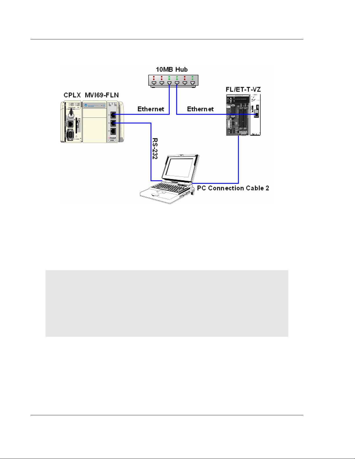
The purpose of this section of the User Manual is to show the MVI69-FLN
functionality through a real application. For this application, the MVI69-FLN
communicates with an FL/ET-T-V2 module (Toyoda) that transfers the data to
the TOYODA PC3JG-P processor located on the same rack.
ProSoft Technology, Inc. Page 9 of 137
November 3, 2008
Page 10
MVI69-FLN ♦ CompactLogix Platform Start Here
FA Control Network Communication Module
For this example, the MVI69-FLN node address is 40, and the FL/ET-T-V2
module node address is 10.
1.1 System Requirements
The MVI69-FLN module requires the following minimum hardware and software
components:
Rockwell Automation CompactLogix or MicroLogix processor, with
compatible power supply and one free slot in the rack, for the MVI69-FLN
module. The module requires 800mA of available power.
Important: The MVI69-FLN module has a power supply distance rating of 2 (L43 and L45
installations on first 2 slots of 1769 bus).
Important: For 1769-L23x processors, please make note of the following limitations.
1769-L23-QBFC1B = 800mA at 5Vdc (1 MVI69-FLN will use all 800mA of available power. No
other modules can be used with an MVI69 module connected to this processor).
1769-L23E-QB1B = 1000mA at 5Vdc (1 MVI69-FLN will use 800mA of available power. One
other module can be used on this rack provided it consumes less than 200mA at 5Vdc.
1769-L23E-QBFC1B = 450mA at 5Vdc (no MVI69 module can be used with this processor)
Rockwell Automation RSLogix 5000 (CompactLogix) or RSLogix 500
(MicroLogix) programming software
Rockwell Automation RSLinx communication software
Pentium® II 450 MHz minimum. Pentium III 733 MHz (or better)
recommended
Supported operating systems:
o Microsoft Windows XP Professional with Service Pack 1 or 2
o Microsoft Windows 2000 Professional with Service Pack 1, 2, or 3
o Microsoft Windows Server 2003
128 Mbytes of RAM minimum, 256 Mbytes of RAM recommended
Page 10 of 137 ProSoft Technology, Inc.
November 3, 2008
Page 11

Start Here MVI69-FLN ♦ CompactLogix Platform
FA Control Network Communication Module
100 Mbytes of free hard disk space (or more based on application
requirements)
256-color VGA graphics adapter, 800 x 600 minimum resolution (True Color
1024 × 768 recommended)
CD-ROM drive
HyperTerminal or other terminal emulator program capable of file transfers
using Ymodem protocol.
1.2 Package Contents
The following components are included with your MVI69-FLN module, and are all
required for installation and configuration.
Important: Before beginning the installation, please verify that all of the following items are
present.
Qty. Part Name Part Number Part Description
1
1 Cable
1 Cable
1
MVI69-FLN
Module
inRAx
Solutions CD
MVI69-FLN FA Control Network Communication Module
Cable #15, RS232
Null Modem
RJ45 to DB9 Male
Adapter
For RS232 Connection to the CFG Port
For DB9 Connection to Module's Port
Contains sample programs, utilities and
documentation for the MVI69-FLN module.
If any of these components are missing, please contact ProSoft Technology
Support for replacement parts.
ProSoft Technology, Inc. Page 11 of 137
November 3, 2008
Page 12
MVI69-FLN ♦ CompactLogix Platform Start Here
FA Control Network Communication Module
1.3 Install ProSoft Configuration Builder Software
You must install the ProSoft Configuration Builder (PCB) software in order to
configure the MVI69-FLN module. You can always get the newest version of
ProSoft Configuration Builder from the ProSoft Technology web site.
To install ProSoft Configuration Builder from the ProSoft Web Site
1 Open your web browser and navigate to http://www.prosoft-
technology.com/pcb
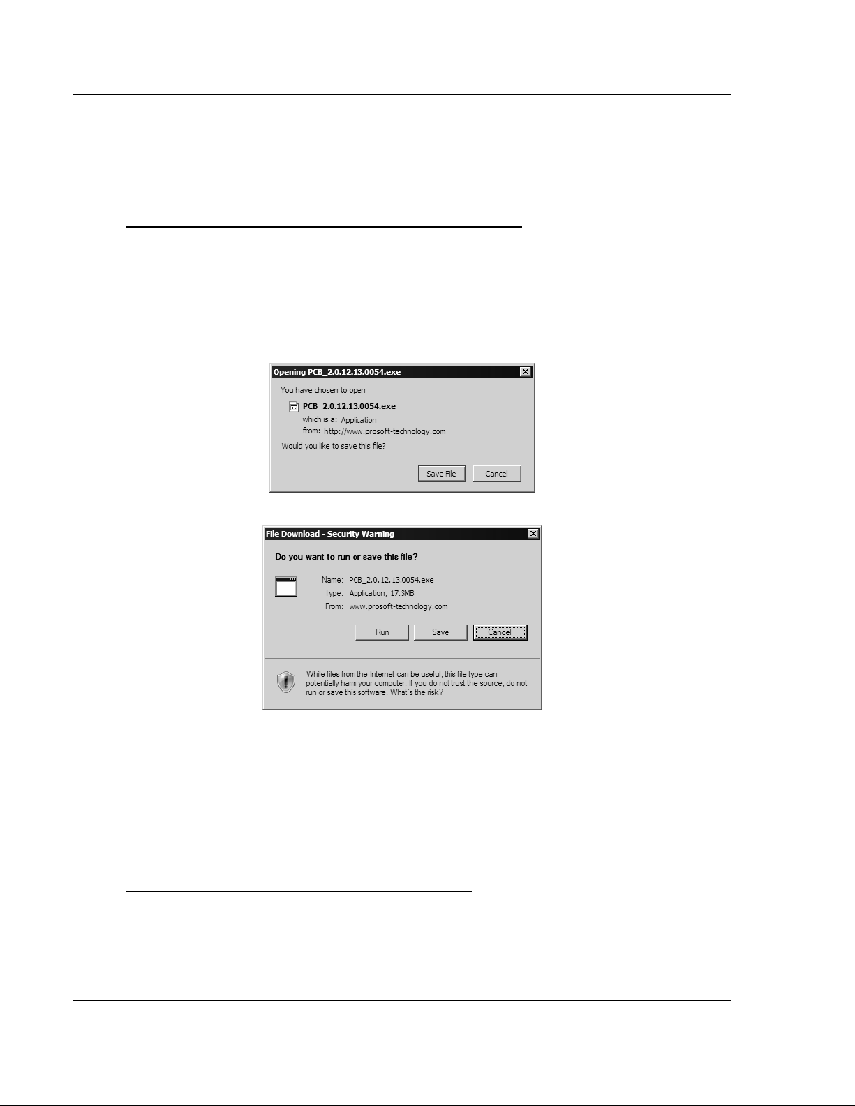
2 Click the Download Here link to download the latest version of ProSoft
Configuration Builder.
3 Choose "Save" or "Save File" when prompted. The following illustrations
show the file download prompt for two of the most common web browsers.
4 Make a note of the location where you saved the file, for example "Desktop",
or "My Documents", so you can start the installation program.
5 When the download is complete, locate and open the file, and then follow the
instructions on your screen to install the program.
If you do not have access to the Internet, you can install ProSoft Configuration
Builder from the ProSoft Solutions CD-ROM, included in the package with your
MVI69-FLN module.
To install ProSoft Configuration Builder from the CD-ROM
1 Insert the ProSoft Solutions CD-ROM into the CD drive of your PC. Wait for
the startup screen to appear.
2 On the startup screen, click Product Documentation. This action opens an
explorer window.
Page 12 of 137 ProSoft Technology, Inc.
November 3, 2008
Page 13
Start Here MVI69-FLN ♦ CompactLogix Platform
FA Control Network Communication Module
3 Click to open the Utilities folder. This folder contains all of the applications
and files you will need to set up and configure your module.
4 Double-click the ProSoft Configuration Builder Setup program and follow the
instructions on your screen to install the software on your PC.
Note: Many of the configuration and maintenance procedures use files and other utilities on the
CD-ROM. You may wish to copy the files from the Utilities folder on the CD-ROM to a convenient
location on your hard drive.
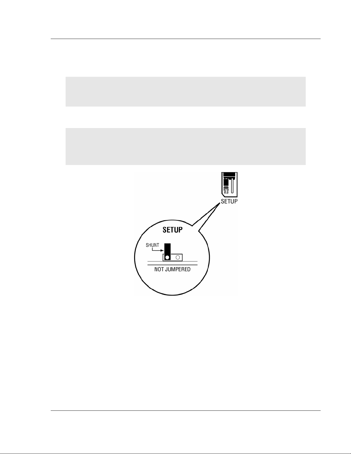
1.4 Setting Jumpers
Note: The Setup Jumper acts as "write protection" for the module's flash memory. In "write
protected" mode, the Setup pins are not connected, and the module's firmware cannot be
overwritten. Do not jumper the Setup pins together unless you are directed to do so by ProSoft
Technical Support.
ProSoft Technology, Inc. Page 13 of 137
November 3, 2008
Page 14
MVI69-FLN ♦ CompactLogix Platform Start Here
FA Control Network Communication Module
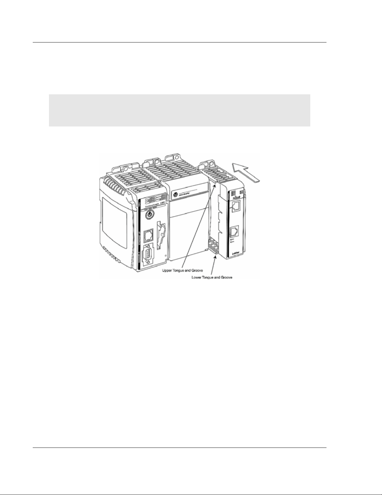
1.5 Install the Module in the Rack
This section describes how to install the module into a CompactLogix rack
Before you attempt to install the module, make sure that the bus lever of the
adjacent module is in the unlocked (fully right) position.
Warning: This module is not hot-swappable! Always remove power from the rack before
inserting or removing this module, or damage may result to the module, the processor, or other
connected devices.
1 Align the module using the upper and lower tongue-and-groove slots with the
adjacent module and slide forward in the direction of the arrow.
2 Move the module back along the tongue-and-groove slots until the bus
connectors on the MVI69 module and the adjacent module line up with each
other.
Page 14 of 137 ProSoft Technology, Inc.
November 3, 2008
Page 15
Start Here MVI69-FLN ♦ CompactLogix Platform
FA Control Network Communication Module
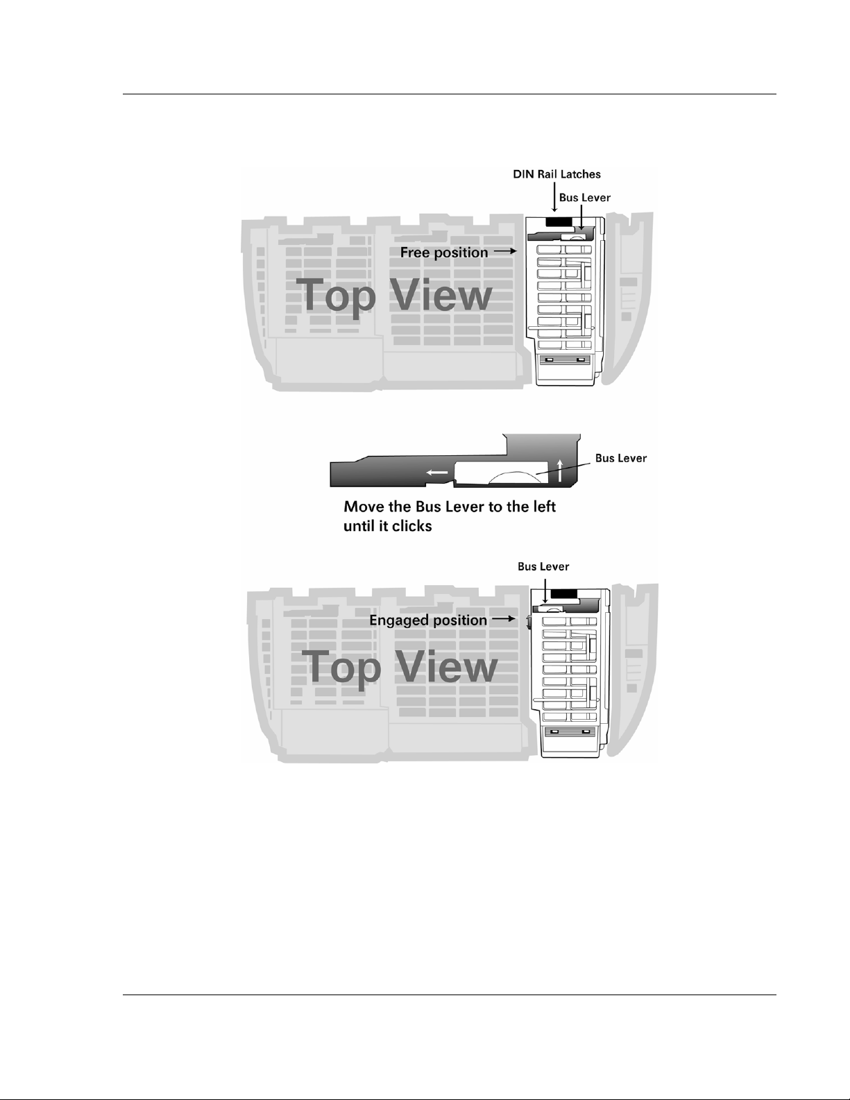
3 Push the module's bus lever back slightly to clear the positioning tab and
move it firmly to the left until it clicks. Ensure that it is locked firmly in place.
4 Close all DIN rail latches.
ProSoft Technology, Inc. Page 15 of 137
November 3, 2008
Page 16
MVI69-FLN ♦ CompactLogix Platform Start Here
FA Control Network Communication Module
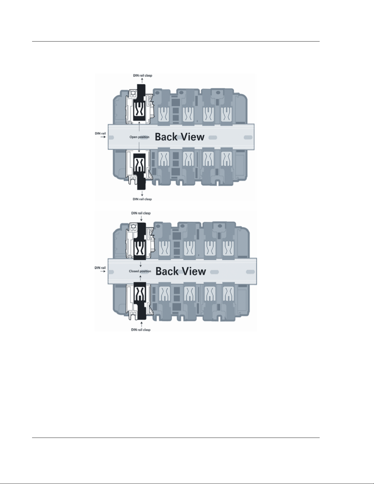
5 Press the DIN rail mounting area of the controller against the DIN rail. The
latches will momentarily open and lock into place.
Page 16 of 137 ProSoft Technology, Inc.
November 3, 2008
Page 17
Start Here MVI69-FLN ♦ CompactLogix Platform
FA Control Network Communication Module
1.6 Installing the Module with a CompactLogix Processor
If you are installing and configuring the module with a CompactLogix processor,
follow these steps. If you are using a MicroLogix processor, refer to the next
section.
Important: The MVI69-FLN module has a power supply distance rating of 2 (L43 and L45
installations on first 2 slots of 1769 bus)
This chapter describes how to install and configure the module to work with your
application. The configuration process consists of the following steps.
1 Use RSLogix to identify the module to the processor and add the module to a
project.
Note: The RSLogix software must be in "offline" mode to add the module to a project.
2 Modify the example ladder logic to meet the needs of your application, and
copy the ladder logic to the processor. Example ladder logic files are provided
on the CD-ROM.
Note: If you are installing this module in an existing application, you can copy the necessary
elements from the example ladder logic into your application.
The rest of this chapter describes these steps in more detail.
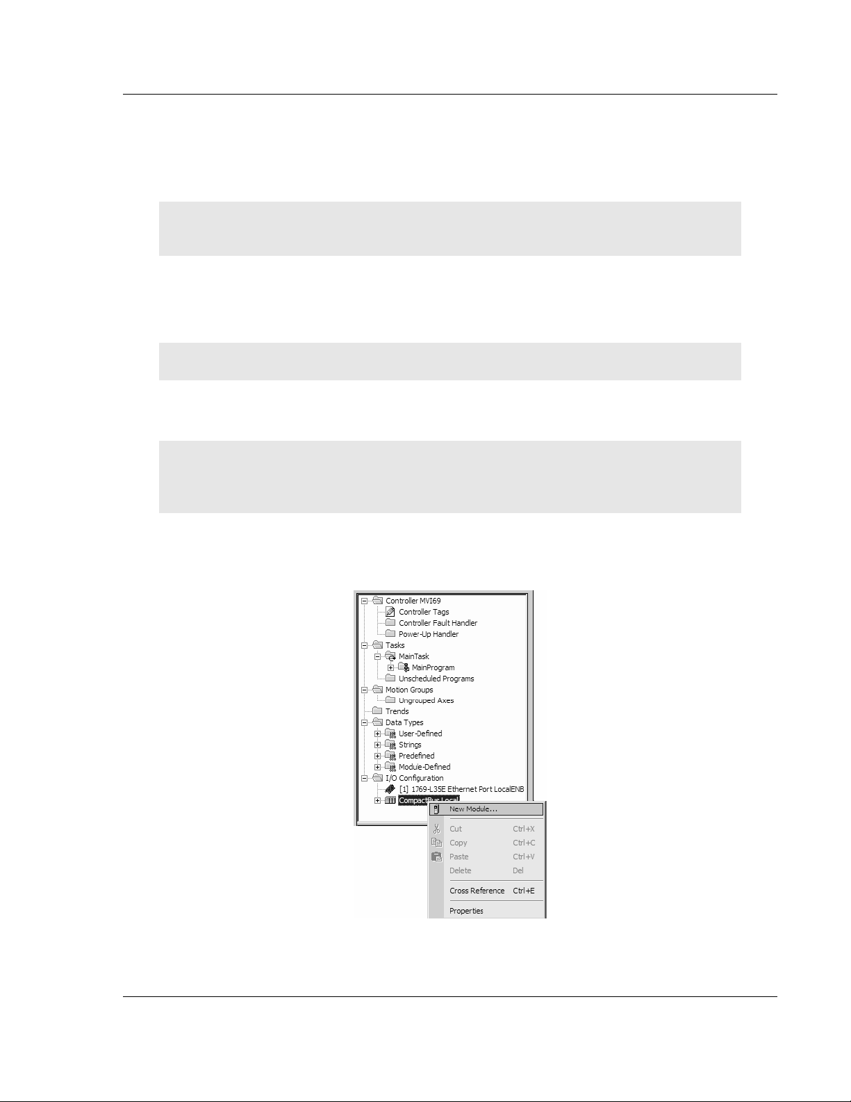
First, define the module to the system. Right-click the mouse button on the I/O
Configuration option in the Controller Organization window to display a pop-up
menu. Select the New Module… option from the I/O Configuration menu.
ProSoft Technology, Inc. Page 17 of 137
November 3, 2008
Page 18
MVI69-FLN ♦ CompactLogix Platform Start Here
FA Control Network Communication Module
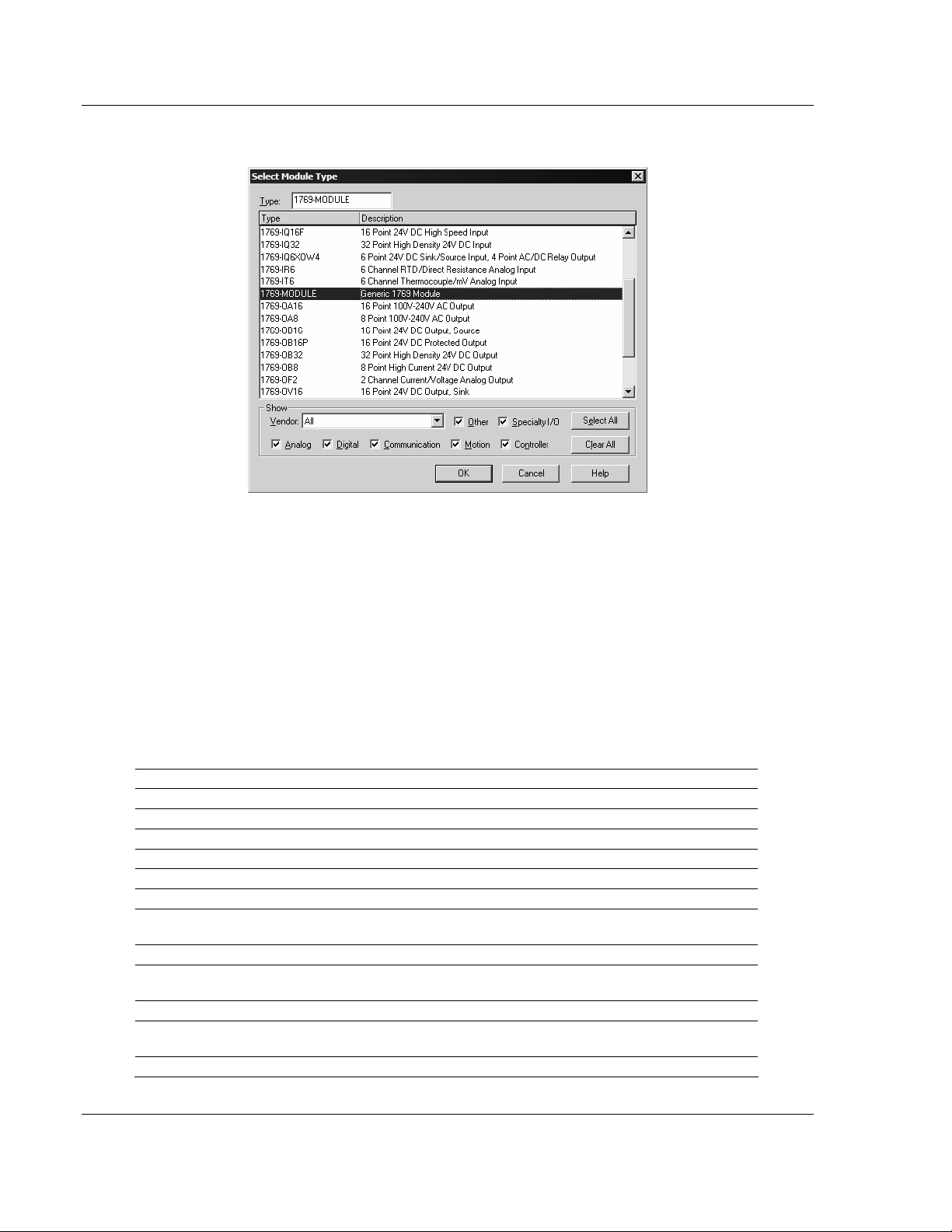
This action opens the Select Module Type dialog box.
Select the 1769-Module (Generic 1769 Module) from the list and click OK.
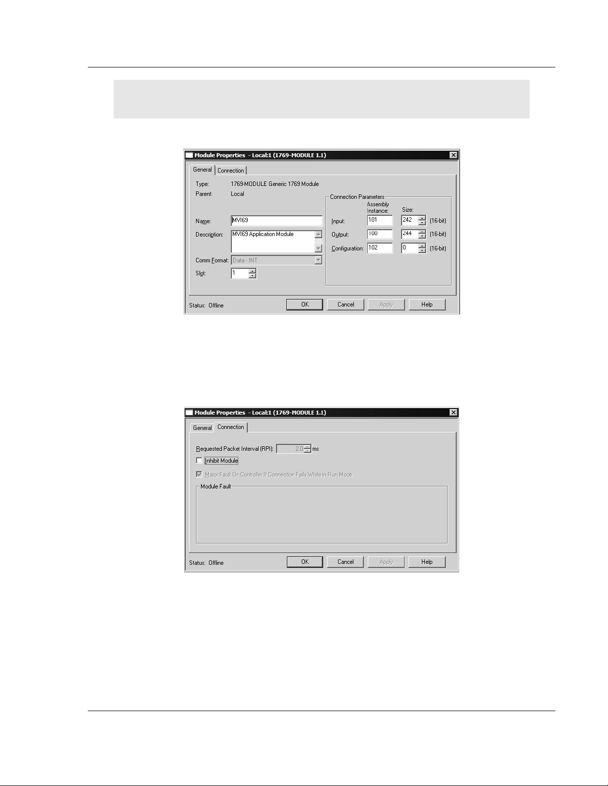
You should configure the Connection Parameters according to the Block Transfer
Size parameter in the configuration file as follows:
On the General page, fill in the values shown in the following tables, according to
the Block Transfer Size parameter in the configuration file. You must select the
Comm Format as Data - INT.
The configured Input Size and Output Size will depend on the block transfer size
parameter defined in the configuration file. Use the values in the table
corresponding with the block transfer size you configured.
Block Transfer Size = 240
Field Recommended Value
Type 1769-MODULE Generic 1769 Module
Parent Local
Name MVI69
Description MVI69 Application Module
Comm Format Data - INT
Slot The slot number in the rack where the module is installed
Input Assembly
Instance
Input Size 242
Output Assembly
Instance
Output Size 244
Configuration
Assembly Instance
Configuration Size 0
101
100
102
Page 18 of 137 ProSoft Technology, Inc.
November 3, 2008
Page 19
Start Here MVI69-FLN ♦ CompactLogix Platform
FA Control Network Communication Module
Important: If you set the Assembly Instance and Size values incorrectly, the module will not
communicate over the backplane of the CompactLogix rack.
Click Next to continue.
Fill in the dialog boxes as shown, adjusting the Name, Description and Slot
options for your application. You must select the Comm Format as Data - INT in
the dialog box. Failure to set the Assembly Instance and Size values correctly
will result in a module that will not communicate over the backplane of the
CompactLogix rack. Click Next to open the next dialog box.
Select the Request Packet Interval value for scanning the I/O on the module.
This value represents the minimum frequency the module will handle scheduled
events. This value should not be set to less than 2 milliseconds.
ProSoft Technology, Inc. Page 19 of 137
November 3, 2008
Page 20

MVI69-FLN ♦ CompactLogix Platform Start Here
FA Control Network Communication Module
1.6.1 Sample Ladder Logic
Important: You must download the sample ladder to the CompactLogix processor, otherwise the
module will be unable to establish communication with the processor.
If you see the message
"Waiting for connection to processor..."
when you connect to the configuration/debug port on the MVI69-FLN module using HyperTerminal,
connect to the processor with RSLogix and download the sample ladder logic to the processor
before continuing.
Open the Sample Ladder Logic in RSLogix
The sample program for your MVI69-FLN module includes custom tags, data
types and ladder logic for data I/O, status and monitoring. For most applications,
you can run the sample ladder program without modification, or, for advanced
applications, you can incorporate the sample program into your existing
application.
Important: The RSLinx service must be installed and running on your computer in order for
RSLogix to communicate with the processor. Refer to your RSLinx and RSLogix documentation for
help configuring and troubleshooting these applications.
To open the sample program
1 Connect an RS-232 serial cable from the COM (serial) port on your PC to the
communication port on the front of the processor.
2 Start RSLogix 5000 and close any existing project that may be loaded.
3 Open the Communications menu and choose Go Online. RSLogix will
establish communication with the processor. This may take a few moments.
4 When RSLogix has established communication with the processor, the
Connected To Go Online dialog box will open.
5 On the Connected to Go Online dialog box, click the Select File button.
6 Choose the sample program file, and then click the Select button.
7 RSLogix will load the sample program.
Next, configure the correct controller type and slot number for your application.
Download the Sample Program to the Processor
To download the sample program from RSLogix 5000 to the CompactLogix processor:
Note: The key switch on the front of the CompactLogix module must be in the REM position.
1 If you are not already online to the processor, open the Communications
menu, and then choose Download. RSLogix will establish communication
with the processor.
2 When communication is established, RSLogix will open a confirmation dialog
box. Click the Download button to transfer the sample program to the
processor.
3 RSLogix will compile the program and transfer it to the processor. This
process may take a few minutes.
Page 20 of 137 ProSoft Technology, Inc.
November 3, 2008
Page 21
Start Here MVI69-FLN ♦ CompactLogix Platform
FA Control Network Communication Module
4 When the download is complete, RSLogix will open another confirmation
dialog box. Click OK to switch the processor from Program mode to Run
mode.
Note: If you receive an error message during these steps, refer to your RSLogix documentation to
interpret and correct the error.
5 To verify that the processor is communicating with the module, open the Main
Program folder in the Controller Organization pane in RSLogix, and doubleclick MainRoutine. You will be able to see the numbers change in Rung 0 of
the MainRoutine program.
Configuring RSLinx
If RSLogix is unable to establish communication with the processor, follow these steps:
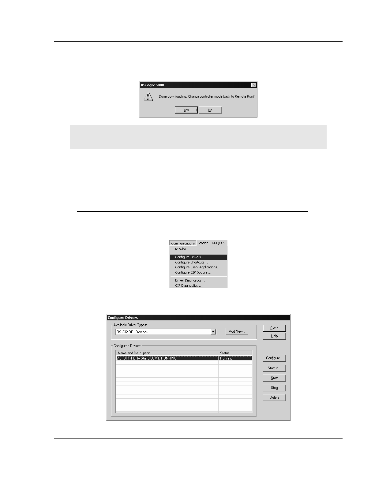
1 Open RSLinx.
2 Open the Communications menu, and choose Configure Drivers.
This action opens the Configure Drivers dialog box.
ProSoft Technology, Inc. Page 21 of 137
November 3, 2008
Page 22
MVI69-FLN ♦ CompactLogix Platform Start Here
FA Control Network Communication Module
Note: If the list of configured drivers is blank, you must first choose and configure a driver from the
Available Driver Types list. The recommended driver type to choose for serial communication with
the processor is "RS-232 DF1 Devices".
3 Click to select the driver, and then click Configure. This action opens the
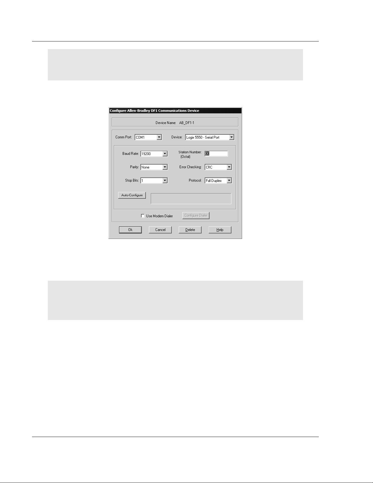
Configure Allen-Bradley DF1 Communications Device dialog box.
4 Click the Auto-Configure button. RSLinx will attempt to configure your serial
port to work with the selected driver.
5 When you see the message "Auto Configuration Successful", click the OK
button to dismiss the dialog box.
Note: If the auto-configuration procedure fails, verify that the cables are connected correctly
between the processor and the serial port on your computer, and then try again. If you are still
unable to auto-configure the port, refer to your RSLinx documentation for further troubleshooting
steps.
Page 22 of 137 ProSoft Technology, Inc.
November 3, 2008
Page 23
Start Here MVI69-FLN ♦ CompactLogix Platform
FA Control Network Communication Module
1.7 Installing and Configuring the Module with a MicroLogix Processor
If you are installing and configuring the module with a MicroLogix processor,
follow these steps. If you are using a CompactLogix processor, refer to the
previous section.
This chapter describes how to install and configure the module to work with your
application. The configuration process consists of the following steps.
1 Use RSLogix to identify the module to the processor and add the module to a
project.
Note: The RSLogix software must be in "offline" mode to add the module to a project.
2 Modify the example ladder logic to meet the needs of your application, and
copy the ladder logic to the processor. Example ladder logic files are provided
on the CD-ROM.
Note: If you are installing this module in an existing application, you can copy the necessary
elements from the example ladder logic into your application.
The rest of this chapter describes these steps in more detail.
The first step in setting up the processor ladder file is to define the I/O type
module to the system. Start RSLogix 500, and follow these steps:
1 In RSLogix, open your existing application, or start a new application,
depending on your requirements.
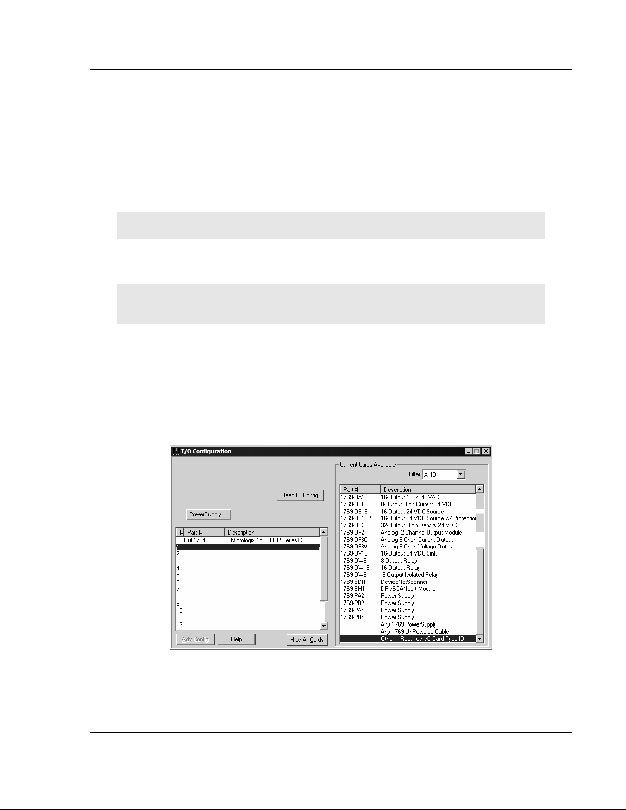
2 Double-click the I/O Configuration icon located in the Controller folder in the
project tree. This action opens the I/O Configuration dialog box.
3 On the I/O Configuration dialog box, select "Other - Requires I/O Card Type
ID" at the bottom of the list in the right pane, and then double-click to open
the Module dialog box.
ProSoft Technology, Inc. Page 23 of 137
November 3, 2008
Page 24
MVI69-FLN ♦ CompactLogix Platform Start Here
FA Control Network Communication Module
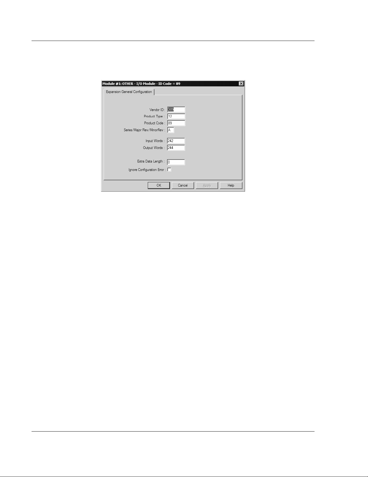
4 Enter the values shown in the following illustration to define the module
correctly for the MicroLogix processor, and then click OK to save your
configuration.
5 Click Next to continue.
6 After completing the module setup, the I/O configuration dialog box will
display the module's presence.
The last step is to add the ladder logic. If you are using the example ladder logic,
adjust the ladder to fit your application. Refer to the example Ladder Logic
section in this manual.
Download the new application to the controller and place the processor in run
mode. If you encounter errors, refer to Diagnostics and Troubleshooting (page
71) for information on how to connect to the module's Config/Debug port to use
its troubleshooting features.
Page 24 of 137 ProSoft Technology, Inc.
November 3, 2008
Page 25
Start Here MVI69-FLN ♦ CompactLogix Platform
FA Control Network Communication Module
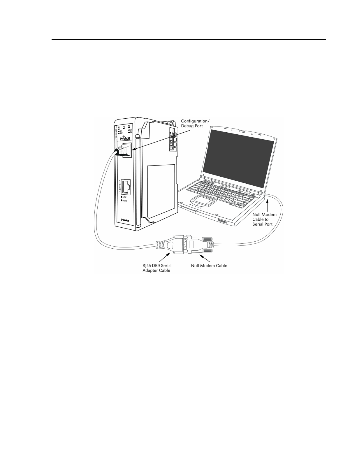
1.8 Connect your PC to the Module
With the module securely mounted, connect your PC to the Configuration/Debug
port using an RJ45-DB-9 Serial Adapter Cable and a Null Modem Cable.
1 Attach both cables as shown.
2 Insert the RJ45 cable connector into the Configuration/Debug port of the
module.
3 Attach the other end to the serial port on your PC or laptop.
1.9 ProSoft Configuration Builder
ProSoft Configuration Builder (PCB) provides a quick and easy way to manage
module configuration files customized to meet your application needs. PCB is not
only a powerful solution for new configuration files, but also allows you to import
information from previously installed (known working) configurations to new
projects.
ProSoft Technology, Inc. Page 25 of 137
November 3, 2008
Page 26
MVI69-FLN ♦ CompactLogix Platform Start Here
FA Control Network Communication Module
1.9.1 Set Up the Project
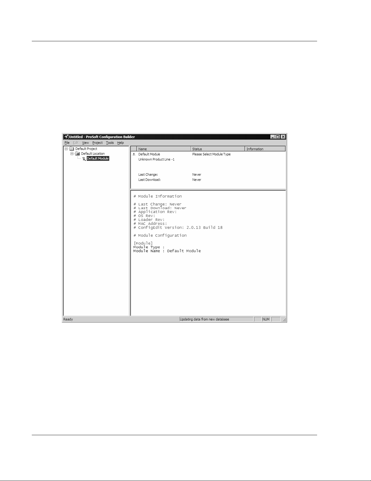
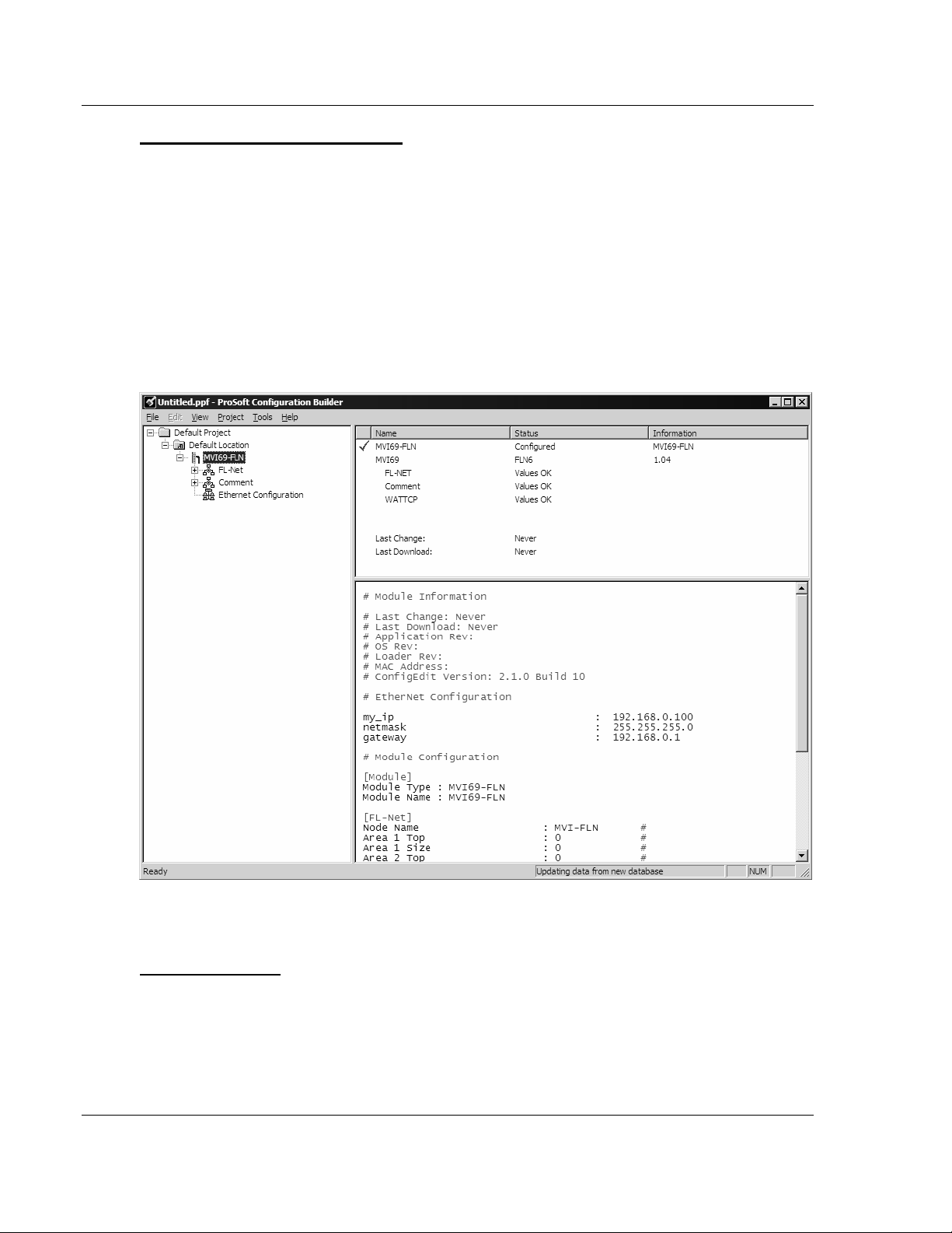
To begin, start ProSoft Configuration Builder. If you have used other Windows
configuration tools before, you will find the screen layout familiar. ProSoft
Configuration Builder's window consists of a tree view on the left, an information
pane and a configuration pane on the right side of the window. When you first
start ProSoft Configuration Builder, the tree view consists of folders for Default
Project and Default Location, with a Default Module in the Default Location
folder. The following illustration shows the ProSoft Configuration Builder window
with a new project.
Your first task is to add the MVI69-FLN module to the project.
1 Use the mouse to select "Default Module" in the tree view, and then click the
right mouse button to open a shortcut menu.
Page 26 of 137 ProSoft Technology, Inc.
November 3, 2008
Page 27
Start Here MVI69-FLN ♦ CompactLogix Platform
FA Control Network Communication Module
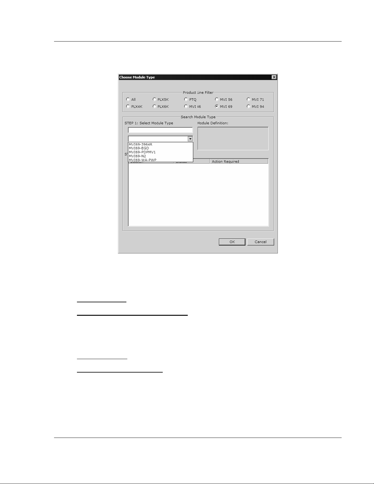
2 On the shortcut menu, choose "Choose Module Type". This action opens the
Choose Module Type dialog box.
3 In the Product Line Filter area of the dialog box, select MVI69. In the Select
Module Type dropdown list, select MVI69-FLN, and then click OK to save
your settings and return to the ProSoft Configuration Builder window.
Adding a Project
To add a project to an existing project file:
1 Select the Default Project icon.
2 Choose Project from the Project menu, then choose Add Project. A new
project folder appears.
Adding a Module
To add a module to your project:
1 Double-click the Default Module icon to open the Choose Module Type dialog
box.
2 On the Choose Module Type dialog box, select the module type.
Or
1 Open the Project menu and choose Location.
2 On the Location menu, choose Add Module.
ProSoft Technology, Inc. Page 27 of 137
November 3, 2008
Page 28
MVI69-FLN ♦ CompactLogix Platform Start Here
FA Control Network Communication Module
To add a module to a different location:
1 Right-click the Location folder and choose Add Module. A new module icon
appears.
Or
1 Select the Location icon.
2 From the Project menu, select Location, then select Add Module.
1.9.2 Set Module Parameters
Notice that the contents of the information pane and the configuration pane
changed when you added the MVI69-FLN module to the project.
At this time, you may wish to rename the "Default Project" and "Default Location"
folders in the tree view.
To rename an object:
1 Select the object, and then click the right mouse button to open a shortcut
menu. From the shortcut menu, choose Rename.
2 Type the name to assign to the object.
3 Click away from the object to save the new name.
Page 28 of 137 ProSoft Technology, Inc.
November 3, 2008
Page 29
Start Here MVI69-FLN ♦ CompactLogix Platform
FA Control Network Communication Module
Module Entries
To configure module parameters
1 Click on the plus sign next to the icon
to expand module
information.
2 Double-click the
icon to open the Edit dialog box.
3 To edit a parameter, select the parameter in the left pane and make your
changes in the right pane.
4 Click OK to save your changes.
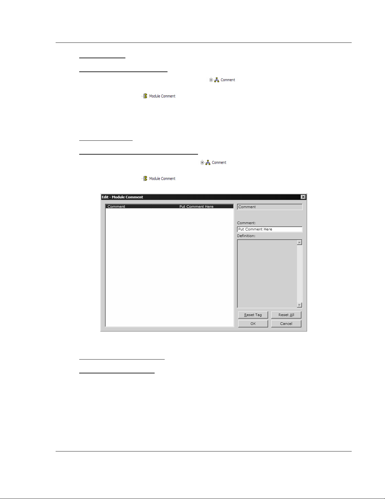
Comment Entries
To add comments to your configuration file:
1 Click the plus sign to the left of the
icon to expand the Module
Comments.
2 Double-click the
icon. The Edit - Module Comment dialog
appears.
3 Enter your comment and click OK to save your changes.
Printing a Configuration File
To print a configuration file:
1 Select the Module icon, and then click the right mouse button to open a
shortcut menu.
2 On the shortcut menu, choose View Configuration. This action opens the
View Configuration window.
3 On the View Configuration window, open the File menu, and choose Print.
This action opens the Print dialog box.
4 On the Print dialog box, choose the printer to use from the dropdown list,
select printing options, and then click OK.
ProSoft Technology, Inc. Page 29 of 137
November 3, 2008
Page 30
MVI69-FLN ♦ CompactLogix Platform Start Here
FA Control Network Communication Module
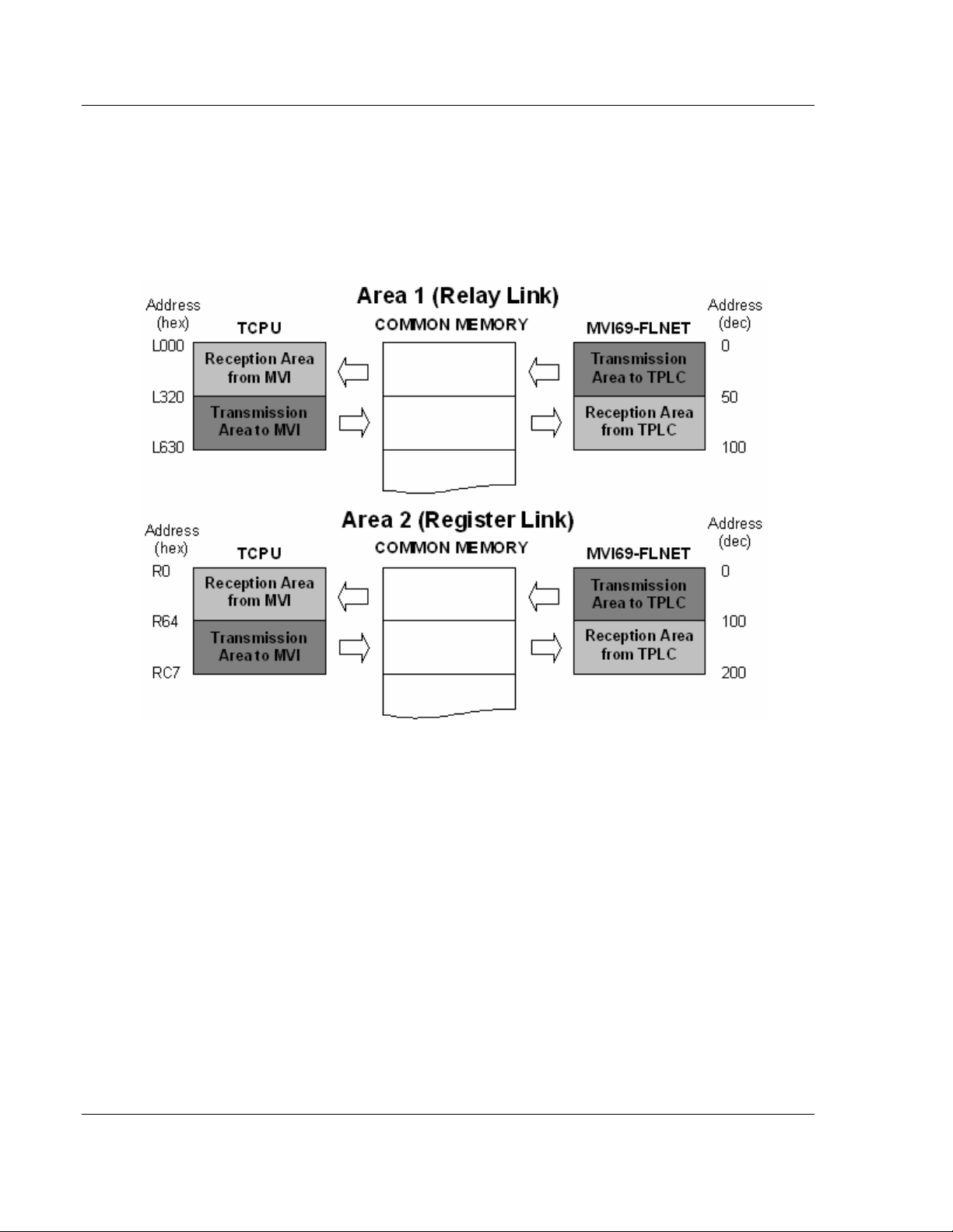
1.10 Configure Area 1 and Area 2
Next, configure the module to properly transfer data between the CompactLogix
processor and the remote FLNET node (Toyoda PLC - TPLC). Each area is
defined by its start address (top address) and word length (size). The following
illustration shows the start addresses and word lengths used in the sample
application:
Refer to the MVI69-FLN configuration file (FLNET.CFG) to configure the module
parameters for data transfer.
Use the following settings to configure the data to transfer from the module to the
remote node. This data is transferred from the CompactLogix processor to the
MVI69-FLN module through the FLNETDATA.Output.Area1 and
FLNETDATA.Output.Area2 controller tag arrays.
Area 1 Top : 0
Area 1 Size : 50
Area 2 Top : 0
Area 2 Size : 100
Use the following settings to configure the data to transfer from the common
memory to the processor. This data is transferred from the MVI69-FLN module to
the CompactLogix processor through the FLNETDATA.Input.Area1 and
FLNETDATA.Input.Area2 controller tag arrays.
BP Area 1 Top : 50
BP Area 1 Size : 50
BP Area 2 Top : 100
BP Area 2 Size : 100
Page 30 of 137 ProSoft Technology, Inc.
November 3, 2008
Page 31

Start Here MVI69-FLN ♦ CompactLogix Platform
FA Control Network Communication Module
The following illustration shows how the data is transferred:
You can increase the area copied to the processor to also include the produced
output data.
The following example shows how the data copied to the processor also includes
the data produced by the module, which is available in the FLNET common
memory.
This data is transferred from the MVI69-FLN module to the CompactLogix
processor through the FLNETDATA.Input.Area1 and FLNETDATA.Input.Area2
controller tag arrays.
BP Area 1 Top : 0
BP Area 1 Size : 100
BP Area 2 Top : 0
BP Area 2 Size : 200
The data read from the remote FLNET starts at FLNETDATA.Input.Area1[50] (50
words) and FLNETDATA.Input.Area2[100] (50 words) controller tag arrays. The
data produced by the module and available at the FLNET common memory
starts at FLNETDATA.Input.Area1[0] (50 words) and FLNETDATA.Input.Area2[0]
(50 words) controller tag arrays.
ProSoft Technology, Inc. Page 31 of 137
November 3, 2008
Page 32

MVI69-FLN ♦ CompactLogix Platform Start Here
FA Control Network Communication Module
1.11 Configure the General Parameters
Configure the general parameters for your application. This example will consider
the following parameters:
Node Name : MVI69FLNET #identifies the node in the FLNET
network
Token Watchdog Time : 100 #token watchdog time (1..255) in ms
#(default=255)
Minimum Frame Interval Time: 20 #allowable min frame interval
#(20...50), #100 microsecond units
Note: Please refer to FL-net Node Configuration (page 97) for more information about these
configuration parameters.
1.12 Data Mapping Functionality
Note: Data Mapping is supported for MVI69-FLN firmware version 1.04 and above only.
The data mapping feature allows the optimization of data transfer from the
module to the ControlLogix processor.
1.12.1 Introduction
You can configure the sections of the A1 and A2 areas to be transferred to the
processor through the following parameters:
BP Area 1 Top : 0 #0...511 top address for area 1
BP Area 1 Size : 200 #0...512 area 1 data size in words
BP Area 2 Top : 0 #0...8191 top address for area 2
BP Area 2 Size : 1440 #0...8192 area 2 data size in words
However, the data associated to the nodes is not necessarily in a contiguous
order. Also, the application may require only specific data from each node that
could be spread over the configured area to be transferred to the processor. This
implementation may lead to the transfer of unused data to the processor, causing
unnecessary delays to the overall module performance.
Example 1
In this example, the module receives data from four different nodes associated to
the Area 2 common memory. Therefore, the module should be configured to
transfer the first 1200 words of data to the processor as follows:
BP Area 2 Top : 0 #0...8191 top address for area 2
BP Area 2 Size : 1440 #0...8192 area 2 data size in words
The module can only transfer a block of 240 words at a time. Therefore, for the
following application, the module would have to transfer unused data in order to
transfer the entire data associated to the four slaves to the processor. The result
is that unused blocks would have to be transferred, resulting in unnecessary
delay to the overall performance.
Page 32 of 137 ProSoft Technology, Inc.
November 3, 2008
Page 33

Start Here MVI69-FLN ♦ CompactLogix Platform
FA Control Network Communication Module
Without Map Feature
The data mapping feature allows you to select data sections associated to each
slave, and select these to be mapped (in any order) into a virtual backplane map
area. This virtual area will be copied to the processor (instead of the entire
common memory area).
This feature allows the module to copy only specific data required for the
application, as shown in the following illustration. Unused data blocks are not
required to be copied:
With Map Feature
Instead of copying six blocks, the module only copies two blocks to send the data
associated to all four nodes. You would also re-configure the portion of the
Virtual BP Map area to be copied to the processor as follows:
BP Area 2 Top : 0 #0...8191 top address for area 2
BP Area 2 Size : 480 #0...8192 area 2 data size in words
ProSoft Technology, Inc. Page 33 of 137
November 3, 2008
Page 34

MVI69-FLN ♦ CompactLogix Platform Start Here
FA Control Network Communication Module
1.12.2 Setting the Mapping Parameters
To set mapping parameters
1 Enable the Use BP Map Table parameter with a value of Y as follows:
Use BP Map Table : Y #Use BP mapping (Y=Use maps, N=Don't use maps
(default))
2 Setup the mapping for your application through the [FL-NET BACKPLANE
MAPPING] section of the configuration file.
Where each parameter is defined as follows:
Parameter Description
Node Node number
A1 Network Start
A1 Network Size
A1 Network Backplane
Start
A2 Network Start
A2 Network Size
A2 Network Backplane
Start
Start word offset in the node area (within the network common
memory) to be mapped into the virtual backplane map. This is not the
absolute offset within the common memory. For example, if the node
top address is 200 (size of 150 words), in order to remap the last 50
words of that node then enter a A1 Network Start value of 100 (not
300).
Total number of words (starting from A1 Network Start offset) to be
mapped into the virtual backplane map.
Start absolute word offset in the virtual backplane map where the
mapped A1 data will be copied to.
Start word offset in the node area (within the network common
memory) to be mapped into the virtual backplane map. This is not the
absolute offset within the common memory. For example, if the node
top address is 200 (size of 150 words), in order to remap the last 50
words of that node then enter a A2 Network Start value of 100 (not
300).
Total number of words (starting from A2 Network Start offset) to be
mapped into the virtual backplane map.
Start absolute word offset in the virtual backplane map where the
mapped A2 data will be copied to.
3 Setup the portion of the virtual backplane map to be transferred to the
processor.
BP Area 1 Top : 0 #0...511 top address for area 1
BP Area 1 Size : 200 #0...512 area 1 data size in words
BP Area 2 Top : 0 #0...8191 top address for area 2
BP Area 2 Size : 200 #0...8192 area 2 data size in words
The following example shows how to use the map feature by configuring the
module parameters.
Page 34 of 137 ProSoft Technology, Inc.
November 3, 2008
Page 35

Start Here MVI69-FLN ♦ CompactLogix Platform
FA Control Network Communication Module
Example 2
This example application requires the MVI69-FLN module to communicate with
two nodes configured as follows:
Node 1
Area 1 Top : 0
Area 1 Size: 150
Area 2 Top : 0
Area 2 Size: 150
Node 2
Area 1 Top : 240
Area 1 Size: 150
Area 2 Top : 240
Area 2 Size: 150
The MVI69-FLN must transfer the following data to the processor:
Entire node 1 data
Last 50 words of node 2 data
Without Data Mapping
In order to disable the data mapping, set the Use BP Map Table parameter as N:
Use BP Map Table : N #Use BP mapping (Y=Use maps, N=Don't use maps
(default))
Because the goal is to transfer the entire Node 1 data and the last 50 words for
Node 2 data, the backplane transfer to the processor should be set as follows:
BP Area 1 Top : 0 #0...511 top address for area 1
BP Area 1 Size : 390 #0...512 area 1 data size in words
BP Area 2 Top : 0 #0...8191 top address for area 2
BP Area 2 Size : 390 #0...8192 area 2 data size in words
Therefore, two blocks per each area will be required to transfer the data as
follows:
Read Block ID Area Start Area Offset Last Area Offset
1 1 0 239
2 1 240 389
4 2 0 239
5 2 240 389
ProSoft Technology, Inc. Page 35 of 137
November 3, 2008
Page 36
MVI69-FLN ♦ CompactLogix Platform Start Here
FA Control Network Communication Module
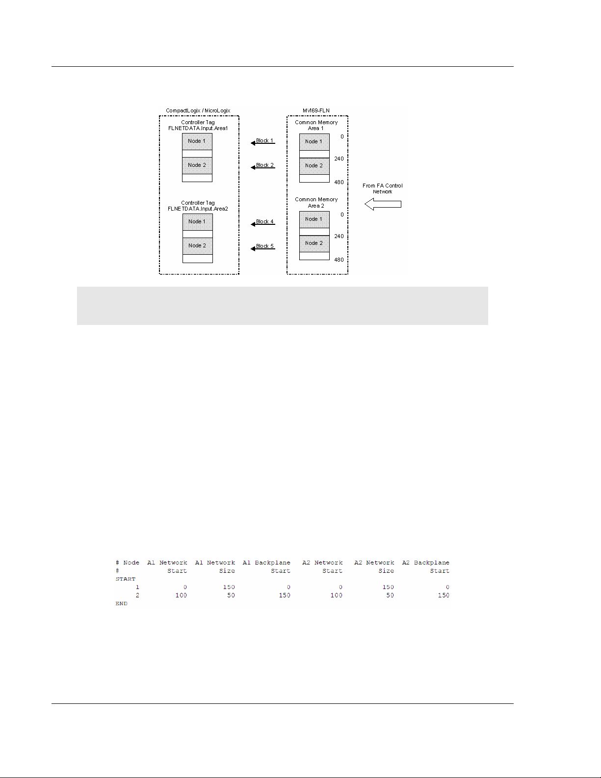
The following illustration demonstrates this application:
Note: This application only requires the last 50 words from Node 2, but it must transfer the entire
data because the transferred data must be organized.
With Data Mapping
In order to enable the mapping feature set the Use BP Map Table parameter as
Y:
Use BP Map Table : Y #Use BP mapping (Y=Use maps, N=Don't use maps
(default))
Now configure the mapping settings through the [FL-NET BACKPLANE
MAPPING] section in the configuration file. The goal is to remap only the areas to
be transferred to the application in a contiguous order to provide optimal
performance.
For this example the application requires only the following areas to me
transferred to the processor (same offsets for both Area 1 and Area 2):
Node 1 = Common Memory Data Offset from 0 to 149
Node 2 = Common Memory Data Offset from 340 to 389
The following illustration shows how to configure this section for this example:
Page 36 of 137 ProSoft Technology, Inc.
November 3, 2008
Page 37

Start Here MVI69-FLN ♦ CompactLogix Platform
FA Control Network Communication Module
The following illustration shows how the data transfer would occur for this
example:
Important: A1 Network Start and A2 Network Start parameters refer to the start offset within each
node’s area. So for this example node 2 mapping was configured as:
A1 Network Start = A2 Network Start = 100
Therefore, the A1/A2 Network Start offsets do not indicate the absolute Common Memory offset
(340 for this example). It indicates the starting offset within that specific node’s area (100 for this
example).
1.13 Configure the Node Number
Configure the MVI69-FLN module with a node number of 40. The last digit of the
IP address is used to denote the node number of the module.
Refer to the configuration file WATTCP.CFG and configure both parameters as
follows:
my_ip=192.168.250.40
netmask=255.255.255.0
ProSoft Technology, Inc. Page 37 of 137
November 3, 2008
Page 38

MVI69-FLN ♦ CompactLogix Platform Start Here
FA Control Network Communication Module
1.14 Download the Project to the Module
In order for the module to use the settings you configured, you must download
(copy) the updated Project file from your PC to the module.
To Download the Project File
1 In the tree view in ProSoft Configuration Builder, click once to select the
MVI69-FLN module.
2 Open the Project menu, and then choose Module / Download. The program
will scan your PC for a valid com port (this may take a few seconds). When
PCB has found a valid com port, the following dialog box will open.
3 Choose the com port to use from the dropdown list, and then click the
Download button.
The module will perform a platform check to read and load its new settings.
When the platform check is complete, the status bar in ProSoft Configuration
Builder will be updated with the message "Module Running".
Page 38 of 137 ProSoft Technology, Inc.
November 3, 2008
Page 39

Start Here MVI69-FLN ♦ CompactLogix Platform
FA Control Network Communication Module
1.15 Cable Connections
The MVI69-FLN module has the following communication connections on the
module:
One Ethernet port (RJ45 connector)
One RS-232 Configuration/Debug port (RJ45 connector)
1.15.1 Ethernet Connection
The MVI69-FLN module has an RJ45 port located on the front of the module
labeled "Ethernet", for use with the TCP/IP network. The module is connected to
the Ethernet network using an Ethernet cable between the module's Ethernet
port and an Ethernet switch or hub.
Note: Depending on hardware configuration, you may see more than one RJ45 port on the
module. The Ethernet port is labeled "Ethernet".
Warning: The MVI69-FLN module is NOT compatible with Power Over Ethernet (IEEE802.3af /
IEEE802.3at) networks. Do NOT connect the module to Ethernet devices, hubs, switches or
networks that supply AC or DC power over the Ethernet cable. Failure to observe this precaution
may result in damage to hardware, or injury to personnel.
Important: The module requires a static (fixed) IP address that is not shared with any other device
on the Ethernet network. Obtain a list of suitable IP addresses from your network administrator
BEFORE configuring the Ethernet port on this module. The last digit of the IP address is used to
denote the node number of the module.
Ethernet Port Configuration - wattcp.cfg
The wattcp.cfg file must be set up properly in order to use a TCP/IP network
connection. You can view the current network configuration using an ASCII
terminal by selecting "@" (Network Menu) and "V" (View) options when
connected to the Debug port.
# WATTCP.CFG FILE:
# ProSoft Technology.
my_ip=192.168.0.40
# Default class 3 network mask
netmask=255.255.255.0
# The gateway I wish to use
gateway=192.168.0.1
ProSoft Technology, Inc. Page 39 of 137
November 3, 2008
Page 40

MVI69-FLN ♦ CompactLogix Platform Start Here
FA Control Network Communication Module
1.15.2 RS-232 Configuration/Debug Port
This port is physically an RJ45 connection. An RJ45 to DB-9 adapter cable is
included with the module. This port permits a PC based terminal emulation
program to view configuration and status data in the module and to control the
module. The cable for communications on this port is shown in the following
diagram:
Disabling the RSLinx Driver for the Com Port on the PC
The communication port driver in RSLinx can occasionally prevent other
applications from using the PC's COM port. If you are not able to connect to the
module's configuration/debug port using ProSoft Configuration Builder (PCB),
HyperTerminal or another terminal emulator, follow these steps to disable the
RSLinx Driver.
1 Open RSLinx and go to Communications>RSWho
2 Make sure that you are not actively browsing using the driver that you wish to
stop. The following shows an actively browsed network:
3 Notice how the DF1 driver is opened, and the driver is looking for a processor
on node 1. If the network is being browsed, then you will not be able to stop
this driver. To stop the driver your RSWho screen should look like this:
Page 40 of 137 ProSoft Technology, Inc.
November 3, 2008
Page 41

Start Here MVI69-FLN ♦ CompactLogix Platform
FA Control Network Communication Module
Branches are displayed or hidden by clicking on the or the icons.
4 When you have verified that the driver is not being browsed, go to
Communications>Configure Drivers
You may see something like this:
If you see the status as running, you will not be able to use this com port for
anything other than communication to the processor. To stop the driver press
the "Stop" on the side of the window:
5 After you have stopped the driver you will see the following:
6 Upon seeing this, you may now use that com port to connect to the debug
port of the module.
Note: You may need to shut down and restart your PC before it will allow you to stop the driver
(usually only on Windows NT machines). If you have followed all of the above steps, and it will not
stop the driver, then make sure you do not have RSLogix open. If RSLogix is not open, and you
still cannot stop the driver, then reboot your PC.
ProSoft Technology, Inc. Page 41 of 137
November 3, 2008
Page 42

MVI69-FLN ♦ CompactLogix Platform Start Here
FA Control Network Communication Module
1.15.3 DB9 to RJ45 Adaptor (Cable 14)
1.16 Setup the FL/ET-T-V2 Module
1.16.1 Set Operation Mode Switch
Select the correct operation mode through the switch (item 3 below)
The following options are available. This procedure will consider the first option
(ID Code = C9 - 8kbytes of Link Memory Capacity)
Page 42 of 137 ProSoft Technology, Inc.
November 3, 2008
Page 43

Start Here MVI69-FLN ♦ CompactLogix Platform
FA Control Network Communication Module
Switch Positions
1 & 2 off C9 8 kbytes Relay link: 2048 points (128 words) (*2)
1 off, 2
on
1 & 2 on E9 32 kbytes Relay link: 2048 points (128 words) (*2)
1 on, 2
off
I/O module
ID Code
D9 16 kbytes Relay link: 2048 points (128 words) (*2)
B3 4 kbytes The module is operated as Ethernet.
Link Memory
Capacity
Data Link Capacity (maximum number of
total words in reception and transmission
areas)
Register link: 2048 words (*1)
Register link: 6144 words (* 1)
Register link: 8192 words (*1)
1.17 FL/ET-V2 Configuration with PCwin
1.17.1 Specify I/O Module ID Code
Expand the Parameter folder, and double-click I/O Module
ProSoft Technology, Inc. Page 43 of 137
November 3, 2008
Page 44

MVI69-FLN ♦ CompactLogix Platform Start Here
FA Control Network Communication Module
Select the FL-net module
1.17.2 Setup the FL/ET-V2 Link Parameters
Double-click Link Parameter
Page 44 of 137 ProSoft Technology, Inc.
November 3, 2008
Page 45

Start Here MVI69-FLN ♦ CompactLogix Platform
FA Control Network Communication Module
Select the link number to assign to the FL/ET-T-V2 module. For this example,
use Link No 1 for the FL/ET-T-V2 module. Double click the link row and configure
the correct slot, rack and module for link 1 as shown in the following illustrations:
Now click the Detail button to configure the following link parameters:
Node Number = 10
Communication Method = N:N or 1:N (Master)
ProSoft Technology, Inc. Page 45 of 137
November 3, 2008
Page 46

MVI69-FLN ♦ CompactLogix Platform Start Here
FA Control Network Communication Module
Click the Data Link button to configure the common memory that will be shared
by all participating nodes in communication.
For this example, the data transfer takes place as described in the following
illustration (the Transmit Area in the TOYODA PLC must be configured inside the
Link Area):
Page 46 of 137 ProSoft Technology, Inc.
November 3, 2008
Page 47

Start Here MVI69-FLN ♦ CompactLogix Platform
FA Control Network Communication Module
Click OK to close the Data Link window, and then click the Network button.
Configure the default parameters as shown in the following illustration:
Note: This configuration sets the node address of the FL/ET-T-V2 module to 192.168.250.10 (the
node address was configured as 10).
For this example, the processor (rack 0 and slot 0) will be assigned as DLNK-M2.
For more information about this topic, refer to the TOYODA PLC documentation.
1.18 Download the Project
Now save the project and download it to the TOYODA PLC.
ProSoft Technology, Inc. Page 47 of 137
November 3, 2008
Page 48

MVI69-FLN ♦ CompactLogix Platform Start Here
FA Control Network Communication Module
1.19 Connect the MVI69-FLN Module to the FL/ET-T-V2
Use standard CA5 Ethernet cables to connect the Ethernet port on the MVI69FLN through a 10 Megabit Ethernet hub or switch to the Ethernet port on the
FL/ET-T-V2 module.
Warning: The MVI69-FLN module is NOT compatible with Power Over Ethernet (IEEE802.3af /
IEEE802.3at) networks. Do NOT connect the module to Ethernet devices, hubs, switches or
networks that supply AC or DC power over the Ethernet cable. Failure to observe this precaution
may result in damage to hardware, or injury to personnel.
1.20 Verifying Communication
This section shows how to monitor the communication status of the configured
FL-net network (assuming that both the FL/ET-T-V2 module and the MVI69-FLN
module were configured according to the previous sections).
1.20.1 Required Hardware
You can connect directly from your computer's serial port to the serial port on the
module to view configuration information, perform maintenance, and send
(upload) or receive (download) configuration files.
ProSoft Technology recommends the following minimum hardware to connect
your computer to the module:
80486 based processor (Pentium preferred)
1 megabyte of memory
At least one UART hardware-based serial communications port available.
USB-based virtual UART systems (USB to serial port adapters) often do not
function reliably, especially during binary file transfers, such as when
uploading/downloading configuration files or module firmware upgrades.
A null modem serial cable.
1.20.2 The Configuration/Debug Menu
The Configuration and Debug menu for this module is arranged as a tree
structure, with the Main Menu at the top of the tree, and one or more sub-menus
for each menu command. The first menu you see when you connect to the
module is the Main menu.
Because this is a text-based menu system, you enter commands by typing the
command letter from your computer keyboard in the terminal application (for
example, HyperTerminal). The module does not respond to mouse movements
or clicks. The command executes as soon as you press the command letter —
you do not need to press [Enter]. When you type a command letter, a new
screen will be displayed in your terminal application.
Important: You must download the sample ladder to the CompactLogix processor, otherwise the
module will be unable to establish communication with the processor.
Page 48 of 137 ProSoft Technology, Inc.
November 3, 2008
Page 49

Start Here MVI69-FLN ♦ CompactLogix Platform
FA Control Network Communication Module
If you see the message
"Waiting for connection to processor..."
when you connect to the configuration/debug port on the MVI69-FLN module
using HyperTerminal, connect to the processor with RSLogix and download the
sample ladder logic to the processor before continuing.
Using the Diagnostic Window in ProSoft Configuration Builder
To connect to the module's Configuration/Debug serial port:
1 Start PCB program with the application file to be tested. Right click over the
module icon.
2 On the shortcut menu, choose Diagnostics.
ProSoft Technology, Inc. Page 49 of 137
November 3, 2008
Page 50

MVI69-FLN ♦ CompactLogix Platform Start Here
FA Control Network Communication Module
3 This action opens the Diagnostics dialog box. Press "?" to display the Main
Menu.
Important: The illustrations of configuration/debug menus in this section are intended as a general
guide, and may not exactly match the configuration/debug menus in your own module.
If there is no response from the module, follow these steps:
1 Verify that the null modem cable is connected properly between your
computer's serial port and the module. A regular serial cable will not work.
2 On computers with more than one serial port, verify that your communication
program is connected to the same port that is connected to the module.
If you are still not able to establish a connection, contact ProSoft Technology for
assistance.
Navigation
All of the sub-menus for this module contain commands to redisplay the menu or
return to the previous menu. You can always return from a sub-menu to the next
higher menu by pressing [M] on your keyboard.
The organization of the menu structure is represented in simplified form in the
following illustration:
Page 50 of 137 ProSoft Technology, Inc.
November 3, 2008
Page 51

Start Here MVI69-FLN ♦ CompactLogix Platform
FA Control Network Communication Module
The remainder of this section shows you the menus available for this module,
and briefly discusses the commands available to you.
Keystrokes
The keyboard commands on these menus are almost always non-case sensitive.
You can enter most commands in lower case or capital letters.
The menus use a few special characters ([?], [-], [+], [@]) that must be entered
exactly as shown. Some of these characters will require you to use the [Shift],
[Ctrl] or [Alt] keys to enter them correctly. For example, on US English
keyboards, enter the [?] command as [Shift][/].
Also, take care to distinguish capital letter [I] from lower case letter [l] (L) and
number [1]; likewise for capital letter [O] and number [0]. Although these
characters look nearly the same on the screen, they perform different actions on
the module.
1.20.3 Using the Module Debug Menu
Checking the Nodes Exchanging Data
From the Main Menu select:
FL-net Menu (F) → Node Data Exchange (D)
This menu contains a table that indicates all nodes that are exchanging data with
the MVI69-FLN module. In the following table, each group of four digits
corresponds to a word (16-bits) displayed in hexadecimal format. This table
describes a sequence of bits that correspond to each FL-net node.
The following tables show the correlation between the bits and the nodes on the
FL-net network for the first three words:
Word 0
Bit # 0 1 2 3 4 5 6 7 8 9 10 11 12 13 14 15
Node # 0 1 2 3 4 5 6 7 8 9 10 11 12 13 14 15
Word 1
Bit # 0 1 2 3 4 5 6 7 8 9 10 11 12 13 14 15
Node # 16 17 18 19 20 21 22 23 24 25 26 27 28 29 30 31
Word 2
Bit # 0 1 2 3 4 5 6 7 8 9 10 11 12 13 14 15
Node # 32 33 34 35 36 37 38 39 40 41 42 43 44 45 46 47
ProSoft Technology, Inc. Page 51 of 137
November 3, 2008
Page 52

MVI69-FLN ♦ CompactLogix Platform Start Here
FA Control Network Communication Module
The following illustration shows that that node 10 is in data exchange mode: the
value 0400 hex indicates that bit 10 is set with a value of 1, and all other bits
have a value of 0.
Checking the Participating Nodes
From the Main Menu select:
FL-net Menu (F)
Nodes Participating (E)
In the following tables, each group of four digits corresponds to a word (16-bits)
displayed in hexadecimal format. This table describes a sequence of bits that
correspond to each FL-net node.
The following tables show the correlation between the bits and the nodes on the
FL-net network for the first three words:
Word 0
Bit # 0 1 2 3 4 5 6 7 8 9 10 11 12 13 14 15
Node # 0 1 2 3 4 5 6 7 8 9 10 11 12 13 14 15
Word 1
Bit # 0 1 2 3 4 5 6 7 8 9 10 11 12 13 14 15
Node # 16 17 18 19 20 21 22 23 24 25 26 27 28 29 30 31
Word 2
Bit # 0 1 2 3 4 5 6 7 8 9 10 11 12 13 14 15
Node # 32 33 34 35 36 37 38 39 40 41 42 43 44 45 46 47
Page 52 of 137 ProSoft Technology, Inc.
November 3, 2008
Page 53

Start Here MVI69-FLN ♦ CompactLogix Platform
FA Control Network Communication Module
The following illustration shows that nodes 10 and 40 are participating: a value of
0400 hex in word 0 indicates that bit 10 is set with a value of 1 and a value of
0100 hex in word 2 indicates that bit 40 is set with a value of 1.
Checking the Log Data
From the Main Menu select:
FL-net Menu (F)
The log data menu displays information pertaining to:
Transmission
Reception
Cyclic Transmission
Display Log Data (L)
ProSoft Technology, Inc. Page 53 of 137
November 3, 2008
Page 54
MVI69-FLN ♦ CompactLogix Platform Start Here
FA Control Network Communication Module
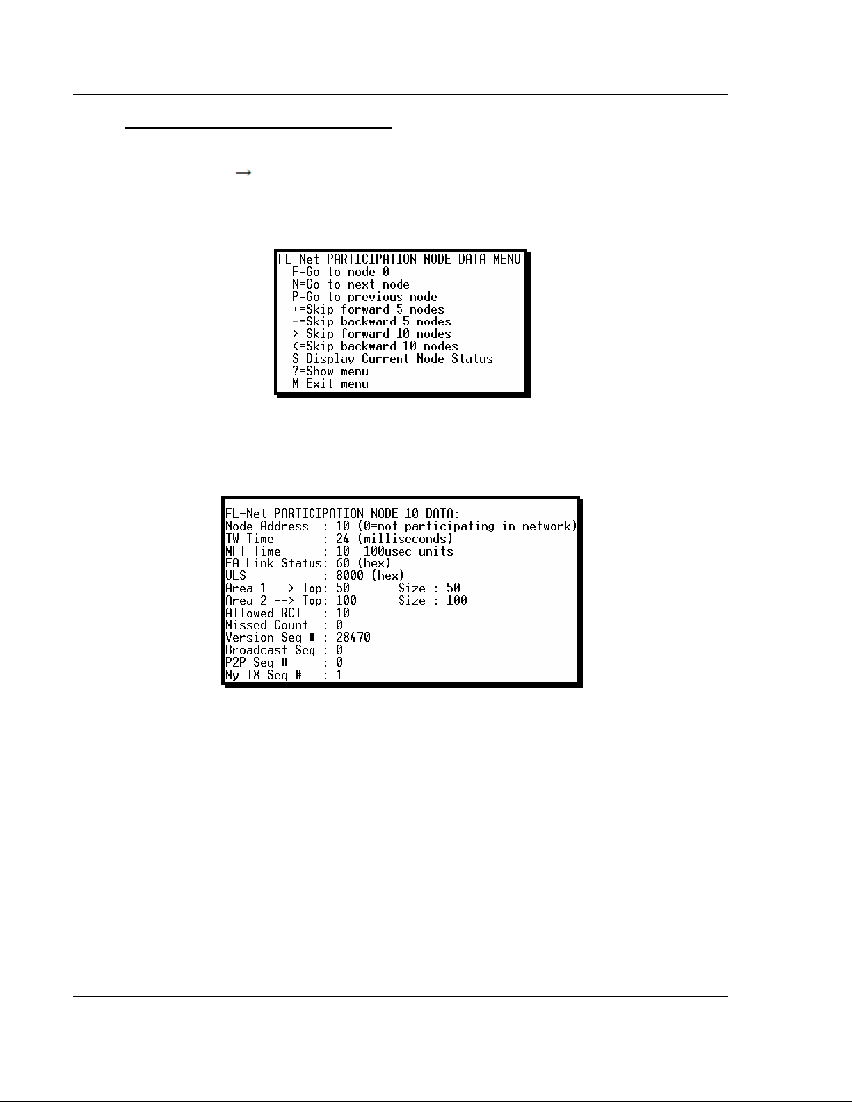
Checking the Participating Node Status
From the Main Menu select:
FL-net Menu (F)
Use the navigation keys to navigate between nodes (next, previous, skip forward,
skip backward).
The following illustration shows the status for node 10. If the Node Address
register indicates a value equal than zero it means that the node is not
participating in the network.
Display Log Data (P)
The Participation Node Data page shows Area 1 and Area 2 settings, FA Link,
Upper Layer Status (ULS) and other values for each participating node.
Page 54 of 137 ProSoft Technology, Inc.
November 3, 2008
Page 55

Start Here MVI69-FLN ♦ CompactLogix Platform
FA Control Network Communication Module
Checking the Own Node Status
From the Main Menu select:
FL-net Menu (F)
Display Own Node Status (1)
The Own Node Data page shows MVI69-FLN status in the FL-net network,
including upper layer status, allowable minimum frame interval time (MFT), Area
1 and Area 2 settings, and other values.
1.20.4 Checking Status through CompactLogix Controller Tags
You can also monitor network status through the CompactLogix controller tags
that are updated through the MVI69-FLN sample ladder. Refer to the ProSoft
Solutions CD-ROM or the ProSoft web site at http://www.prosoft-technology.com
(http://www.prosoft-technology.com) for the sample ladder logic for the MVI69FLN module.
THE FLNETSTATUS controller tag contains status information that is copied
from the module and the processor.
ProSoft Technology, Inc. Page 55 of 137
November 3, 2008
Page 56

MVI69-FLN ♦ CompactLogix Platform Start Here
FA Control Network Communication Module
Checking the Own Node Status
Monitor the FLNETSTATUS.Own_node controller tag for MVI69-FLN status
information. This tag includes the upper layer status (UL), allowable minimum
frame interval time (MFT), token watchdog time (TW), protocol, Area 1 and Area
2 settings for the MVI69-FLN.
The information in this tag is updated automatically from the module through
status blocks 0 and -1.
Page 56 of 137 ProSoft Technology, Inc.
November 3, 2008
Page 57

Start Here MVI69-FLN ♦ CompactLogix Platform
FA Control Network Communication Module
Checking the Nodes Exchanging Data
Monitor the FLNETSTATUS.General.Nodes_Exchanging_Data_Table[ ]
controller tag to see if each node is currently exchanging data. The following
illustration shows that only node 10 is currently exchanging data with the MVI69FLN module: bit 10 of
FLNETSTATUS.General.Nodes_Exchanging_Data_Table[0] word is set to 1 (hex
value of 0400). The information in this tag is updated automatically from the
module through status blocks 0 and -1.
ProSoft Technology, Inc. Page 57 of 137
November 3, 2008
Page 58

MVI69-FLN ♦ CompactLogix Platform Start Here
FA Control Network Communication Module
Checking the Participation Table
Monitor the FLNETSTATUS.General.Nodes_Participating_Count controller tag to
see the number of nodes currently participating in the network. The information in
this tag is updated automatically from the module through status blocks 0 and -1.
Monitor the FLNETSTATUS.General.Nodes_Participating_Table[ ] controller tag
to check if each node is currently participating in the FL-net network. The
following illustration shows that only nodes 10 and 40 are participating.
Bit 10 of FLNETSTATUS.General.Nodes_Exchanging_Data_Table[0] word is
set as 1 (hex value of 0400)
Bit 8 of FLNETSTATUS.General.Nodes_Exchanging_Data_Table[2] word is
set as 1 (hex value of 0100).
Bit 8 of FLNETSTATUS.General.Nodes_Exchanging_Data_Table[2]
corresponds with bit 40 for the entire participating table.
The following illustration shows that currently there are 2 nodes participating.
Page 58 of 137 ProSoft Technology, Inc.
November 3, 2008
Page 59

Start Here MVI69-FLN ♦ CompactLogix Platform
FA Control Network Communication Module
Checking the Participating Node Status
To retrieve the participation node status, the processor must request special
block 2000 (Participation Table Request) from the module. This special block
transfer request allows the processor to retrieve status information for each
participating node. Status registers include:
upper layer status (ULS)
allowable minimum frame interval time (MFT)
allowable refresh cycle time (RCT)
Area 1 (A1) and Area 2 (A2) settings
token watchdog time (TW).
Each block can retrieve status for up to 10 participating nodes. The user
application must initially select the number of nodes to retrieve (up to 10) and the
first node address to retrieve.
For example, to retrieve the status for participating node address 10 (1 node
only), set the controller tags as shown in the following illustrations:
Next, trigger the Participation Table Request block (block 2000). To do this, set
the FLNETMODULE.CONTROL.GetParticipation bit to 1. The following rung in
the sample ladder WriteData routine performs the request to the module. The
FLNETMODULE.CONTROL.GetParticipation bit is automatically cleared after the
response is received from the module.
ProSoft Technology, Inc. Page 59 of 137
November 3, 2008
Page 60

MVI69-FLN ♦ CompactLogix Platform Start Here
FA Control Network Communication Module
The following rung in the Read Data routine reads the module response
containing the participating node status.
Note: The sample ladder will copy the status for 10 nodes. Edit this logic according to the number
of nodes to be read for your application.
Page 60 of 137 ProSoft Technology, Inc.
November 3, 2008
Page 61

Start Here MVI69-FLN ♦ CompactLogix Platform
FA Control Network Communication Module
The participating node status is read to the FLNETSTATUS.Participation[ ]
controller tag array. The status for node address 10 is available at
FLNETSTATUS.Participation[0].
ProSoft Technology, Inc. Page 61 of 137
November 3, 2008
Page 62

MVI69-FLN ♦ CompactLogix Platform Start Here
FA Control Network Communication Module
Checking the Log Data
To retrieve the Log Data, the processor must request special block 9250 (Log
Data Block) from the module.
The following rung in the Write Data routine requests block 9250. To trigger this
logic, set the FLNETMODULE.CONTROL.GetParticipation bit to 1.
Page 62 of 137 ProSoft Technology, Inc.
November 3, 2008
Page 63

Start Here MVI69-FLN ♦ CompactLogix Platform
FA Control Network Communication Module
The processor will eventually receive the block response from the module, and
the following rung in the Write Data routine will automatically clear the
FLNETMODULE.CONTROL.GetParticipation bit and read the block response to
the correct tags.
ProSoft Technology, Inc. Page 63 of 137
November 3, 2008
Page 64

MVI69-FLN ♦ CompactLogix Platform Start Here
FA Control Network Communication Module
You can view the Log Data read from the module in the FLNETSTATUS.LogData
controller tag, as shown in the following illustration:
Checking the General Network Status
Monitor the FLNETSTATUS.Network for general FL-net network information:
the token node that is currently holding the token
the refresh cycle measurement time (RMT) - minimum, maximum and current
values
allowable minimum frame interval time (MFT)
allowable refresh cycle time (RCT).
This information is available in the FLNETSTATUS.General controller tag.
Page 64 of 137 ProSoft Technology, Inc.
November 3, 2008
Page 65

Start Here MVI69-FLN ♦ CompactLogix Platform
FA Control Network Communication Module
Checking the Backplane status
Monitor the FLNETSTATUS.Backplane controller tag for information about
backplane status.
1.20.5 Transferring Data
The sample ladder logic automatically updates the data with the
FLNETDATA.Output and FLNETDATA.Input controller tags. The Area 1 data is
divided into blocks 1 to 3. The Area 2 data is divided into blocks 4 to 35. Each
block contains up to 240 words of data.
The data received from the remote FL-net node to the MVI69-FLN module is
automatically "reassembled" from the input blocks into the FLNETDATA.Intput
controller tag (according to each block ID). Also, the data to transfer from the
module to the remote FL-net node is copied from the FLNETDATA.Output
controller tag into the output blocks according to its block ID. This logic is already
handled by the sample ladder program supplied by ProSoft.
For this example, use the following MVI69-FLN Area1 and Area 2 settings in the
FLNET.CFG configuration file:
Area 1 Top : 0 #0...511 top address for area 1
Area 1 Size : 50 #0...512 area 1 data size in words (0=not used)
Area 2 Top : 0 #0...8191 top address for area 1
Area 2 Size : 100 #0...8192 area 2 data size in words (0=not used)
BP Area 1 Top : 50 #0...511 top address for area 1
BP Area 1 Size: 50 #0...512 area 1 data size in words (0=none transferred)
BP Area 2 Top : 100 #0...8191 top address for area 1
BP Area 2 Size: 100 #0...8192 area 2 data size in words (0=none transferred)
Important: The module only generates the blocks required to transfer the data you configured. For
this example only one Area 1 block and one Area 2 blocks are required, so only blocks 1 to 4 are
used for data transfer. The larger the areas, the more blocks are required to transfer data (and the
more time is required to update the whole block).
ProSoft Technology, Inc. Page 65 of 137
November 3, 2008
Page 66

MVI69-FLN ♦ CompactLogix Platform Start Here
FA Control Network Communication Module
In this example, configure the FL/ET-T-V2 module with the values in the following
illustration:
Transferring Data from MVI69-FLN (Area 1) to FL/ET-T-V2 module (Relay Area)
The FLNETDATA.Output.Area1 controller tags transfer data from the module
Area 1 to the remote FL-net node Relay link area. For this example, use the
values in the following illustration:
Page 66 of 137 ProSoft Technology, Inc.
November 3, 2008
Page 67

Start Here MVI69-FLN ♦ CompactLogix Platform
FA Control Network Communication Module
Use the PCWin Register Address Monitor to monitor the value set by the module
(address L00W for our example).
ProSoft Technology, Inc. Page 67 of 137
November 3, 2008
Page 68

MVI69-FLN ♦ CompactLogix Platform Start Here
FA Control Network Communication Module
Transferring Data from FL/ET-T-V2 Link Area to MVI69-FLN Area 1
Use the PCWin Register Address Monitor to set the value to transfer to the
module (address L32W for this example)
Use FLNETDATA.Input.Area1 controller tags to monitor data received from the
remote node to the MVI69-FLN Area 1.
Page 68 of 137 ProSoft Technology, Inc.
November 3, 2008
Page 69

Start Here MVI69-FLN ♦ CompactLogix Platform
FA Control Network Communication Module
Transferring Data from MVI69-FLN (Area 2) to FL/ET-T-V2 module (Register
Area)
Use the FLNETDATA.Output.Area2 controller tags to transfer data from the
module Area 1 to the remote FL-net node Relay link area. For this example, use
the values in the following illustration:
Use the PCWin Register Address Monitor to monitor the value set by the module
(address R000 for our example).
ProSoft Technology, Inc. Page 69 of 137
November 3, 2008
Page 70

MVI69-FLN ♦ CompactLogix Platform Start Here
FA Control Network Communication Module
Transferring Data from FL/ET-T-V2 Register Area to MVI69-FLN Area 2
Use the PCWin Register Address Monitor to set the value to transfer to the
module (address R0064 for this example)
Use the FLNETDATA.Input.Area2 controller tags to monitor data received from
the remote node to the MVI69-FLN Area 2.
Page 70 of 137 ProSoft Technology, Inc.
November 3, 2008
Page 71

Diagnostics and Troubleshooting MVI69-FLN ♦ CompactLogix Platform
FA Control Network Communication Module
2 Diagnostics and Troubleshooting
In This Chapter
Basic Ethernet.......................................................................................71
LED Status Indicators............................................................................72
Ethernet LED Indicators ........................................................................72
Troubleshooting.....................................................................................73
The module provides information on diagnostics and troubleshooting in the
following forms:
Status data values are transferred from the module to the processor.
Data contained in the module can be viewed through the
Configuration/Debug port attached to a terminal emulator.
LED status indicators on the front of the module provide information on the
module's status.
2.1 Basic Ethernet
The Ethernet Unit is provided with a variety of troubleshooting functions for
prompt recovery in case of errors.
Self-diagnostic function at startup
PING command for checking other nodes
Inter-nodal tests for checking other nodes
Error log for recording error history data
ProSoft Technology, Inc. Page 71 of 137
November 3, 2008
Page 72

MVI69-FLN ♦ CompactLogix Platform Diagnostics and Troubleshooting
FA Control Network Communication Module
2.2 LED Status Indicators
LED Description
COM Indicates Rx/Tx activity on the Ethernet interface.
LER/LE Communication Error and FA Link present.
This LED will be illuminated when any of the following conditions exist:
Bad frame recognized on FA Link
Error recognized on FA Link
Own Status Errors:
Watchdog timeout error
Receive wait error
Link Status Errors:
Out-ringed
Communication invalidity bit set
ERR/ER
BP ACT
BATT This LED indicates if the battery on the module is low or failed.
LINK
This LED indicates several conditions. If the LED illuminates solid green, there are
no error conditions recognized. If the LED illuminates solid red, there is a major
problem with the module and it may need to be replaced. If the LED blinks red and
green, there is a parameter error present. The conditions which cause a parameter
error are as follows:
Own Status Errors:
Node duplication address detected
Initialization error
Link Status Errors:
Address overlap error
This LED indicates backplane activity. The LED should flash very quickly when
backplane activity is present.
This LED on the Ethernet card indicates that the module recognizes the connection
to the hub or switch.
2.3 Ethernet LED Indicators
LED State Description
Off No activity on the port. Data
Green Flash The port is either actively transmitting or receiving data.
Off No connection to hub or network is detected. Link
Green Solid
Page 72 of 137 ProSoft Technology, Inc.
Connected to hub or network correctly. This is the normal
operating state.
November 3, 2008
Page 73

Diagnostics and Troubleshooting MVI69-FLN ♦ CompactLogix Platform
FA Control Network Communication Module
2.4 Troubleshooting
2.4.1 Own-Node Status information
The Own Node Status register (displayed on the Own Node Status menu)
contains the following information:
Own Status Byte
Bit Message Description Value
0
1 TW Error (1=Error)
2 Rx Wait Error (1=Error)
3
4 Reserved 0x0010
5 Reserved 0x0020
6 Reserved 0x0040
7 0x0080
Node address duplicate
(1=Error)
Initialization Error
(1=Error)
Indicates the management information on
node number conflicted to see whether any
node having the same node number as the
self node setting exists on the network or not.
Token watchdog time error flag indicates that
transmission processing fails to complete
within the token watchdog time set in the own
node
Indicates that no frame has been received at
network initialization, being a frame receive
waiting status.
Indicates an error is found in an initial setting
or resetting parameter
0x0001
0x0002
0x0004
0x0008
Link Status Byte
The FA-Link Status register (displayed on the Own Node Status menu) contains
the following information:
Bit Message Description Value
0
1
2 Always 0
3 Always 0
4
5
6
7
*Node Status (1=Out-ring,
0=In-ring)
*Communication Invalid
(1=Yes, 0=No)
Upper Layer Error Signal
(1=Error)
Common Memory Valid
(1=Valid)
Common Memory Set
(1=Complete)
Address Overlap
(1=Error,0=No Error)
Indicates whether the node is in-ringed or outringed
0x0002
0x0004
0x0008
Indicates that the updating of the existence
signal of the upper layer cannot be recognized
Indicates the cycle data is valid 0x0020
Indicates that the setting in the common
memory of the node is completed
Indicates that there is a duplication in the
common memory among the nodes connected
to the network
0x0001
0x0010
0x0040
0x0080
*Only reported to the processor and not network where these bits are always
clear.
ProSoft Technology, Inc. Page 73 of 137
November 3, 2008
Page 74

MVI69-FLN ♦ CompactLogix Platform Diagnostics and Troubleshooting
FA Control Network Communication Module
Upper Layer Status Word
The Upper Layer Status can be set by the CompactLogix processor o the
module. Refer to Upper Layer Status Read Definition (page 92) for more
information.
Bit Message Description Value
0 to 11 Error Code (User Defined) 0x0001
12 reserved 0x1000
Bit 15 = 1 Bit 15 = 0 13 1=Warning, 0=No Warning
The upper layer
program is running with
an error but both cyclic
data and message data
are guaranteed.
14 1=Alarm, 0=No Alarm
15 1=Run, 0=Stop Run Stop 0x8000
Both cyclic data and
message data are not
guaranteed.
The upper layer
program is at a stop
with an error but both
cyclic data and
message data are
guaranteed.
Both cyclic data and
message data are not
guaranteed.
0x2000
0x4000
Page 74 of 137 ProSoft Technology, Inc.
November 3, 2008
Page 75

Reference MVI69-FLN ♦ CompactLogix Platform
FA Control Network Communication Module
3 Reference
In This Chapter
Product Specifications...........................................................................75
Functional Overview..............................................................................77
Implementation of FL-net.......................................................................89
FL-net Node Configuration Parameters.................................................97
FL-net Protocol and network .................................................................99
Error and Status Data..........................................................................111
FL-net Device Profile for MVI69-FLN Module ......................................112
Communications Management Tables................................................115
State Transition Diagram.....................................................................117
Glossary..............................................................................................126
3.1 Product Specifications
The PC56-FLN FA Control Network communication module is a single slot
solution that allows CompactLogix I/O compatible processors to easily interface
with other FL-net protocol compatible devices. The module implements FL-net
version 2.00 (OPCN-2) defined by JEMA (The Japan Electrical Manufacturers
Association) for the standard FA control network. FL-net is a master-less system.
The PC56-FLN module acts as a gateway between the FL-net network and the
Allen-Bradley backplane. The data transfer from the CompactLogix processor is
asynchronous from the actions on the FL-net network. The module's internal
database can be used to exchange Area 1 and Area 2 cyclic, network, and
module status data between the processor and the FL-net network.
3.1.1 General Specifications
Single Slot - 1769 backplane compatible
The module is recognized as an Input/Output module and has access to
processor memory for data transfer between processor and module
Ladder Logic is used for data transfer between module and processor.
Sample ladder file included.
Configuration data obtained from configuration text file downloaded to
module. Sample configuration file included.
Supports all CompactLogix processors: L20/L23/L30/L31/L32/L35, L43 and
L45 (L43 and L45 supported with RSLogix 5000 v16.03 or later)
Also supports MicroLogix 1500 LRP
ProSoft Technology, Inc. Page 75 of 137
November 3, 2008
Page 76

MVI69-FLN ♦ CompactLogix Platform Reference
FA Control Network Communication Module
3.1.2 Hardware Specifications
Specification Description
Dimensions Standard 1769 Single-slot module
Current Load
Operating Temp. 0 to 60°C (32 to 140°F)
Storage Temp. -40 to 85°C (-40 to 185°F)
Relative Humidity 5 to 95% (non-condensing)
LED Indicators
CFG Port (CFG)
App Port (Ethernet modules)
Shipped with Unit
800 mA max@ 5 VDC
Power supply distance rating of 2 (L43 and L45
installations on first 2 slots of 1769 bus)
Power and Module Status
Application Status
CFG Port Activity
Ethernet Port Activity
Error Status
RJ45 (DB-9M with supplied cable)
RS-232 only
No hardware handshaking
10/100 Base-T Ethernet compatible interface
Electrical Isolation 1500 V rms at 50 Hz to 60 Hz for 60 s,
applied as specified in section 5.3.2 of IEC 60950: 1991
Ethernet Broadcast Storm Resiliency = less than or equal
to 5000 [ARP] frames-per-second and less than or equal
to 5 minutes duration
RJ45 to DB-9M cables for each port
6-foot RS-232 configuration Cable
3.1.3 Functional Specifications
Message transfer:
Server Functionality
o Log data read service
o Log data clear service
o Network Parameter Read
o Return Message
o Profile Read
Network Management Table: According to FL-net version 2.00 specification
Own-node Management Table: According to FL-net version 2.00 specification
Participating Node Management Table: According to FL-net version 2.00
specification
Network configurable via a text file
Status and Error information
Page 76 of 137 ProSoft Technology, Inc.
November 3, 2008
Page 77

Reference MVI69-FLN ♦ CompactLogix Platform
FA Control Network Communication Module
3.2 Functional Overview
3.2.1 About FL-net Protocol
FL-net is an open FA network that was standardized by the Japan FA Open
Systems Promotion Group (JOP) of the Manufacturing Science and Technology
Center (MSTC) under the Ministry of International Trade and Industry (MITI). It
has been established in the Japan Electrical Manufacturers standards (JEM
1479) and is becoming very popular.
FL-net enables personal computers and FA controllers, such as programmable
controllers (PLCs) or computerized numeric controllers (CNCs), by different
manufacturers to be interconnected, controlled, and monitored, as shown in the
following illustration.
The following illustration shows the positioning of the FL-net.
FL-net (Version 2.00) Unit specifications have been designed to conform to
Japan Electrical Manufacturers standards (JEM 1479: 2001). It cannot be
connected to communications devices based on the previous standards (JEM
1479: 2000).
The most recent FL-net specifications can be downloaded from the home page of
the Japan Electrical Manufacturers Association (http://www.jemanet.or.jp/Japanese/hyojun/opcn_e/opcn07.htm (http://www.jemanet.or.jp/japanese/hyojun/opcn_e/opcn07.htm)
User-defined Specifications
1 User-defined specifications allow the following range of features that are
required for FA systems.
2 Large-scale network
Up to 254 devices (nodes) can be connected in the physical layer of the
network.
"1 through 254" shall be used as node number. However, numbers "250
through 254" are reserved for maintenance purposes. Number "0" shall not
be used.
Number "255" shall be used as the global address for broadcasting.
ProSoft Technology, Inc. Page 77 of 137
November 3, 2008
Page 78

MVI69-FLN ♦ CompactLogix Platform Reference
FA Control Network Communication Module
3 Dual communications functions to suit application
The Common Memory function uses cyclic transmission so that each node
can always share the same data with other nodes on the network. FL-net also
supports message communications for use when handling only essential data
is required.
4 Large-capacity Common Memory
The Common Memory is provided with a large capacity of 8K bits (Area 1)
and 8K words (Area 2).
5 High-speed response
High-speed response time of 50 milliseconds / 32 nodes (for 2K bits and 2K
words) is provided. The absence of a master in the FL-net network enables
nodes to be added or removed readily without affecting any other nodes. This
allows any node to be turned ON or OFF easily and facilitates maintenance.
The FL-net protocol is characterized by the following items:
1 Transmission control using masterless token system avoids collision.
2 Refresh cycle time can be specified since the system circulates a token in a
fixed time.
3 The token is transmitted together with a cyclic data.
4 The node with a smallest node number among those who participate the
network at start-up time shall start to send the token.
5 If no token is transmitted for a specified period, next node in the token
circulation ring shall send a new token.
6 The masterless token system (characterized by the above two items) will
keep the network from stopping in case of failure of some nodes.
7 The protocol provides information management tables for useful information
to refer operation status of other nodes such as operation mode (RUN /
STOP) and hardware malfunction (ALARM).
Data Communication Between Nodes
Types of Data Communication
The FL-net protocol supports 2 types of data communication.
1 Cyclic transmission for cyclic data transmission
2 Message transmission for non-cyclic data transmission
Cyclic transmission
The common memory size is 8k bits + 8k words = 8.5k words in a whole network.
Available amount of transmission data in one node is 8.5k words at maximum.
One word consists of 2 bytes.
Message transmission
Maximum data length of one message frame is 1024 bytes (excluding header).
Page 78 of 137 ProSoft Technology, Inc.
November 3, 2008
Page 79

Reference MVI69-FLN ♦ CompactLogix Platform
FA Control Network Communication Module
Cyclic Transmission Function
Cyclic transmission means a function that supports cyclic data exchange
between nodes.
Basic functions
1 The cyclic transmission implements common memory interface.
2 Each node sends its whole data while it holds the token.
3 Nodes having no cyclic data are acceptable.
Common memory
1 The common memory interface provides nodes with a service that can be
regarded as a memory shared among them.
2 Two area types (Area 1 and Area 2) may be assigned for a node.
3 Multiple frames may be used if the transmitting area size of a node exceeds
the transmission size of one frame, that is, 1024 bytes.
4 The common memory will not update itself with receiving data until all frames
from a node are successfully received in case of the item (3).Thus time
coherency of data from a node is guaranteed.
5 Communication unit of each node shall provide fixed area of 8k bits + 8k
words = 8.5k words as the common memory.
6 Both Area 1 and Area 2 can be set at any size within the maximum.
Data Share Function
Each node on a FL-net has specific transmission area in the common memory
that does not overlap with others. A transmission area assigned to one node
must be receiving area for other nodes.
Each node broadcasts its data in a fixed cycle and all the nodes in a network
share the same data on the common memory.
ProSoft Technology, Inc. Page 79 of 137
November 3, 2008
Page 80

MVI69-FLN ♦ CompactLogix Platform Reference
FA Control Network Communication Module
Common Memory Function
A node can use the whole common memory as receiving area.
Node for Reception Only
Page 80 of 137 ProSoft Technology, Inc.
November 3, 2008
Page 81

Reference MVI69-FLN ♦ CompactLogix Platform
FA Control Network Communication Module
The FA link protocol allows the existence of nodes which do not have common
memory because there is no transmission and reception data of cyclic but
message transmission only.
Node Having No Common Memory
Area 1 and area 2
A node shall be assigned two data areas, area 1 and area 2, as the transmitting
areas in its common memory.
A transmitting area is defined by the top address and size of the area.
Access to the area is made by word address. Area 1 consists of 0.5k word and
area 2 consists of 8k words.
ProSoft Technology, Inc. Page 81 of 137
November 3, 2008
Page 82

MVI69-FLN ♦ CompactLogix Platform Reference
FA Control Network Communication Module
Assignment of Area 1 and Area 2
Common memory area size that one node should have
A node that is intended to perform cyclic transmission must have a common
memory area size of 8.5k words.
A node that is not intended to perform cyclic transmission does not need to have
any common memory area.
For more information about FL-net please refer the FL-net Protocol
Specifications Version 1.0: MSTC / JOP-1012
Page 82 of 137 ProSoft Technology, Inc.
November 3, 2008
Page 83

Reference MVI69-FLN ♦ CompactLogix Platform
FA Control Network Communication Module
3.2.2 Module Power Up
Main Logic Loop
3.2.3 Backplane Data Transfer
MVI69-FLN Block Assignments Summary
In order to exchange data with the processor, the MVI69-FLN module supports
the following block. The block range refers to the Block ID used to identify each
block.
Input Data
Block Range Descriptions
0 & -1 Status Data
1 to 3 Area 1 Data From Common Memory
4 to 35 Area 2 Data Fr om Common Memory
2000 Participation Table Response
9250 Log Data Block
ProSoft Technology, Inc. Page 83 of 137
November 3, 2008
Page 84

MVI69-FLN ♦ CompactLogix Platform Reference
FA Control Network Communication Module
Output Data
Block Range Descriptions
0 & -1 Empty Data Blocks
1 to 3 Area 1 Data To Common Memory
4 to 35 Area 2 Data T o Common Me mory
2000 Participation Table Request
9250 Log Data Block Request
9998 Warm-boot control block
9999 Cold-boot control block
Read Block
Area 1 Input (Read) Data Block
Offset Description Length
0 Read Block ID (1 to 3) 1
1 Write Block ID Requested 1
2 to 241 Area 1 data from field 240
Area 2 Input (Read) Data Block
Offset Description Length
0 Read Block ID (4 to 38) 1
1 Write Block ID Requested 1
2 to 241 Area 2 data from field 240
Write Block
Empty Output (Write) Data Block
Offset Description Length
0 Write Block ID (-1 or 0) 1
1 to 240 Reserved 240
241 Command Byte 1
242 Upper Layer Status for Module 1
243 Reserved 1
Area 1 Output (Write) Data Block
Offset Description Length
0 Write Block ID (1 to 3) 1
1 to 240 Area 1 Data to field 240
241 Command Byte 1
242 Upper Layer Status for Module 1
243 Reserved 1
Page 84 of 137 ProSoft Technology, Inc.
November 3, 2008
Page 85

Reference MVI69-FLN ♦ CompactLogix Platform
FA Control Network Communication Module
Area 2 Output (Write) Data Block
Offset Description Length
0 Write Block ID (4 to 38) 1
1 to 240 Area 1 Data to field 240
241 Command Byte 1
242 Upper Layer Status for Module 1
243 Reserved 1
Special Blocks
Participation Table Request (Write Block) Output Data
Offset Description Length
0 2000 1
1 Number of nodes to report (1 to 10) 1
2 Index of first node (0 to 255) 1
3 to 243 Spare 241
Participation Table Response (Read Block) Input Data
Offset Description Length
0 2000 1
1 Write Block ID Requested 1
2 Number of nodes to reported (0 to 10) 1
3 to 22 Participation Data first node 20
23 to 42 Participation Data second node 20
43 to 62 Participation Data third node 20
63 to 82 Participation Data fourth node 20
83 to 102 Participation Data fifth node 20
103 to 122 Participation Data sixth node 20
123 to 142 Participation Data seventh node 20
143 to 162 Participation Data eighth node 20
162 to 182 Participation Data ninth node 20
183 to 202 Participation Data tenth node 20
203 to 241 Spare 39
Participation Data Structure (20 words)
Offset Description Words
0 Node Number 1
1 Node Number (0 if not participating) 1
2 Token watchdog time 1
3 Allowable minimum frame interval 1
4 FL Link status 1
5 Upper layer status 1
6 Top Area 1 1
ProSoft Technology, Inc. Page 85 of 137
November 3, 2008
Page 86

MVI69-FLN ♦ CompactLogix Platform Reference
FA Control Network Communication Module
Offset Description Words
7 Size Area 1 1
8 Top Area 2 1
9 Size Area 2 1
10 Allowable refresh cycle time 1
11 Missed count 1
12 to 13 Rx Version sequence number 2
14 to 15 Rx Broadcast sequence number 2
16 to 17 Rx Peer-to-peer sequence number 2
18 to 19 Tx Peer-to-peer sequence number 2
Log Data Request (Write Block) Output Data
Offset Description Length
0 9250 1
1 to 243 Spare 243
Log Data Request (Write Block) Output Data
Offset Description Length
0 9250 1
1 Write Block ID Requested 1
2 to 3 Socket Tx count 2
4 to 5 Socket Tx error count 2
6 to 7 Socket Rx count 2
8 to 9 Socket Rx error count 2
10 to 11 Tokens Tx 2
12 to 13 Cyclic Tx 2
14 to 15 Peer-to-peer message Tx 2
16 to 17' Broadcast message Tx 2
18 to 19 Tokens Rx 2
20 to 21 Cyclic Rx 2
22 to 23 Peer-to-peer message Rx 2
24 to 25 Broadcast message Rx 2
26 to 27 Cyclic Rx errors 2
28 to 29 Cyclic Rx address size errors 2
30 to 31 Cyclic Rx CBN errors 2
32 to 33 Cyclic Rx TBN errors 2
34 to 35 Cyclic Rx BSIZE errors 2
36 to 37 Message retrans 2
38 to 39 Message over retrans 2
40 to 41 Message Rx errors 2
42 to 43 Message Rx version sequence errors 2
44 to 45 Message sequence retrans errors 2
46 to 47 ACK errors 2
Page 86 of 137 ProSoft Technology, Inc.
November 3, 2008
Page 87

Reference MVI69-FLN ♦ CompactLogix Platform
FA Control Network Communication Module
Offset Description Length
48 to 49 ACK version sequence errors 2
50 to 51 ACK sequence errors 2
52 to 53 ACK node number errors 2
54 to 55 ACK TCD errors 2
56 to 57 Token multiple errors 2
58 to 59 Token discards 2
60 to 61 Token reissued 2
62 to 63 Token holding timeouts 2
64 to 65 Token monitoring timeouts 2
66 to 67 Total service time (seconds) 2
68 to 69 Frames waiting 2
70 to 71 Number of nodes participating 2
72 to 73 Self exits 2
74 to 75 Exits by skipping 2
76 to 77 Exits of other nodes 2
78 to 79 Spare 2
80 Node holding token 1
81 Network allowable min frame interval 1
82 Network allowable refresh cycle time 1
83 Current measured refresh cycle time 1
84 Maximum refresh cycle time 1
85 Minimum refresh cycle time 1
86 to 241 Spare 156
ProSoft Technology, Inc. Page 87 of 137
November 3, 2008
Page 88

MVI69-FLN ♦ CompactLogix Platform Reference
FA Control Network Communication Module
3.2.4 Data Flow between Module and Processor
The following discussion outlines the flow of data between the two pieces of
hardware (CompactLogix processor and MVI69-FLN module) and other nodes on
the TCP/IP network.
Module's Cyclic Input Data
Module's Cyclic Output Data
Page 88 of 137 ProSoft Technology, Inc.
November 3, 2008
Page 89

Reference MVI69-FLN ♦ CompactLogix Platform
FA Control Network Communication Module
3.3 Implementation of FL-net
The following two classes are defined considering differences among necessities
of FL-net transmission functions for various devices.
Class Cyclic transmission Message transmission Class
Sending Receiving Client function Server function
1 Mandatory Mandatory Optional Optional
2 Not applicable Optional Optional Optional
Notes:
1 "Sending "of "cyclic transmission" indicates a function that the node allocates
common memory and that it transmits data in the common memory of the
own node to other nodes cyclically.
2 "Receiving "of "cyclic transmission" indicates a function that the system
receives data from the common memory of other nodes cyclically.
3 The "client function" of "message transmission" indicates a function that the
node transmits request messages and that it receives response messages.
4 The "server function" of "message transmission" indicates that the node
processes request messages and that it returns response messages.
3.3.1 Information Tables
Types of management table
Node status management is divided into self-node management table,
participating node management table, and network management table.
1 The self-node management table manages the settings of the self-node.
2 The participating node management table manages the information of the
nodes of in-ring the network.
3 The network management table manages the common network information.
The MVI69-FLN module conforms to the mandatory items in the following tables.
For more information refer to Status Data.
Table name Information Conforming level
Own-node
management
Table
Node number
Area 1 data top address Optional (Supported)
Area 1 data size Optional (Supp orted)
Area 2 data top address Optional (Supported)
Area 2 data size Optional (Supp orted)
Upper layer status
Token watchdog time Optional (Supported)
Allowable minimum frame interval time Optional (Supported)
Vendor code Optional
Manufacturer model name Optional (Supported: Vendor Model)
Node name Optional (Supported)
Protocol type Optional (Supported)
FA link status Mandatory (Supported)
Own-node status Mandatory (Supported)
Mandatory
Mandatory
ProSoft Technology, Inc. Page 89 of 137
November 3, 2008
Page 90

MVI69-FLN ♦ CompactLogix Platform Reference
FA Control Network Communication Module
Table name Information Conforming level
Participating node
management table
Network
management table
Node number Mandatory (Supported)
Upper layer status
Area 1 data top address
Area 1 data size
Area 2 data top address
Area 2 data size
Allowable refresh cycle time Optional (Supported)
Token monitoring time Optional (Not Supported)
Allowable minimum frame interval time Optional (Supported)
FA link status
Token holding node number Optional (Supported)
Allowable minimum frame interval time
Allowable refresh cycle time Optional (Supported)
Refresh cycle measurement time
(Current value)
Refresh cycle measurement time
(Maximum value)
Refresh cycle measurement time
(Minimum value)
Mandatory
Mandatory
Mandatory
Mandatory
Mandatory
Mandatory
Mandatory
Mandatory
Optional (Supported)
Optional (Supported)
Own node management table
This table manages the data on the settings of the self-node.
1 The table is used to network parameter read and participation request
frames.
2 Management data is set from the FA link protocol upper layer at the node
startup time.
3 The node names and the top addresses and size of the transmitting area in
the common memory can be set from the network.
Own node management table
Table name Size Description
(1) Node number (1 byte) 1 to 254
(2) Area 1 data top address in
common memory
(3) Area 1 data size in common
memory
(4) Area 2 data top address in
common memory
(5) Area 2 data size in common
memory
(6) Upper layer status (2 bytes)
(7) Token watchdog time (1 byte) 1 to 255 (1 ms. Units)
(8) Allowable minimum frame
interval
(9) Vender code (10 byte) Vender code
(2 bytes) Word address (0 to 0x1ff)
(2 bytes) Size (0 to 0x1ff)
(2 bytes) Word address (0 to 0x1fff)
(2 bytes) Size (0 to 0x1fff)
RUN / STOP / ALARM / WARNING /
NORMAL
See status block for additional information
(1 byte) 10 to 50 (in units of 100ms.)
Page 90 of 137 ProSoft Technology, Inc.
November 3, 2008
Page 91

Reference MVI69-FLN ♦ CompactLogix Platform
FA Control Network Communication Module
Table name Size Description
(10) Manufacture Model name (10 bytes) Manufacture Model name , device name
(11) Node name (equipment
name)
(12) Protocol version (1 byte) 0x80 (fixed)
(13) FA link status (1 byte) in-ring / out-ring, etc.
(14) Self-node status (1 byte) Node number conflict detection, etc.
(10 bytes) Node name set by user
Participating Node Management Table
The node status of each node joining in the network is monitored by the
management table held by each node. Regarding the nodes joining the network,
this table handles the data to be managed for each node.
1 At a start, participating node management table and the network
management table is created in accordance with the received token frame.
2 Upon receipt of each token frame, each node updates the participating node
management table.
3 Upon receipt of the participation request frame for new joining, the joining
node management table is updated.
4 When non-reception of a token frame of each node or a timeout is detected 3
times running, the corresponding node is deleted from the table.
Table name Size Description
(1) Node number (1 byte) 1 to 254
(2) Upper layer status (2 bytes)
(3) Area 1 data top address in
common memory
(4) Area 1 data size in common
memory
(5) Area 2 data top address in
common memory
(6) Area 2 data size in common
memory
(7) Allowable refresh cycle time (2 bytes) 1 ms. (unit)
(8) Token watchdog time (1 byte) 1 to 255 (1 ms. Units)
(9) Allowable minimum frame
interval
(10) Link status (1 byte) in-ring / out-ring information, etc.
(2 bytes) Word addr ess (0 to 0x1ff)
(2 bytes) Size (0 to 0x1ff)
(2 bytes) Word address (0 to 0x1fff)
(2 bytes) Size (0 to 0x1fff)
(1 byte) 1 to 50 (in units of 100ms.)
RUN / STOP / ALARM / WARNING /
NORMAL
See status block for additional information
Network management table
This table manages the parameters related to the network status.
Table name Size Description
(1) Token holding node number (1 b yte) Node currently holding a token
(2) Allowable minimum frame interval (1 byte) 1 to 50 (in units of 100ms.)
(3) Allowable refresh cycle time (2 byte) 1 ms. (unit)
ProSoft Technology, Inc. Page 91 of 137
November 3, 2008
Page 92

MVI69-FLN ♦ CompactLogix Platform Reference
FA Control Network Communication Module
Table name Size Description
(4) Refresh cycle measurement time
(present value)
(5) Refresh cycle measurement time
(maximum value)
(6) Refresh cycle measurement value
(minimum value)
(2 byte) 0 to 65535 (in 1 ms(unit)
(2 byte) 1 ms. (unit)
(2 byte) 1 ms. (unit)
Upper Layer Status Read Definition
The node status is divided into two types: FA link protocol upper layer status
(referred to as the upper layer status) and FA link protocol status (referred to as
the FA link status).
Upper layer status
The upper layer status is divided into upper layer operation information and
upper layer error information.
Upper layer operation information
RUN: Indicates that the upper layer program is running.
STOP: Indicates that the upper layer program is at a stop.
Upper layer error information
NORMAL: Indicates that the upper layer is normal and both cyclic data and
message data are guaranteed.
WARNING: Indicates that there occurs an error that permits continuing
operation in the upper layer but both cyclic data and message data are
guaranteed.
ALARM: Indicates that there occurs an error that does not permit continuing
operation in the upper layer and both cyclic data and message data are not
guaranteed.
Contents of error in the upper layer: Indicates the contents of an error in the
upper layer program.
The upper layer program means those that have an interface with the FA link
protocol upper layer, which for the MVI-FLN module is he CompactLogix
processor.
Upper Layer Status Table
Operation Information
Error information Run Stop
NORMAL
WARNING
ALARM
The upper layer program is running
and both cyclic data and message
data are guaranteed.
The upper layer program is running
with an error but both cyclic data
and message data are guaranteed.
Both cyclic data and message data
are not guaranteed.
The upper layer program is at a stop
but both cyclic data and message data
are guaranteed.
The upper layer program is at a stop
with an error but both cyclic data and
message data are guaranteed.
Both cyclic data and message data
are not guaranteed.
Page 92 of 137 ProSoft Technology, Inc.
November 3, 2008
Page 93

Reference MVI69-FLN ♦ CompactLogix Platform
FA Control Network Communication Module
The Upper Layer Status word is structured as follows:
Upper Layer Status Word
Bit Description Value
0 to 11 Error Code (User Defined) 0x0001
12 reserved 0x1000
13 1=Warning, 0=No Warning 0x2000
14 1=Alarm, 0=No Alarm 0x4000
15 1=Run, 0=Stop 0x8000
The output blocks that transfer Area 1 and Area 2 data from the CompactLogix to
the MVI69-FLN module (blocks 1 to 38) update the Upper Layer Status through
word offset 247. The sample ladder logic uses the
FLNETMODULE.CONTROL.UpperLayerStatus controller tag to update the upper
layer status.
For example, to set a warning condition, set this controller tag as shown in the
following illustration:
You can monitor the Upper Layer Status from the Display Own Node Status
command in the Configuration/Debug menu.
ProSoft Technology, Inc. Page 93 of 137
November 3, 2008
Page 94

MVI69-FLN ♦ CompactLogix Platform Reference
FA Control Network Communication Module
FA link status
The information on link status is divided into two types: information shared on the
network and information to be managed by each node.
In-ring and out-ring of each node are managed in units of node. All information
except the above is shared on the network.
Message Description
Address overlapping detection
Common memory setting
completion
Common memory data validity Indicates that cyclic data is effective.
Upper layer operation signal error
Node in-ring / out-ring
Indicates that there is any overlapping setting in the common
memory of a node connected to the network.
Indicates that the setting in the common area of a node is
completed.
Indicates that updating of the existence signal of the upper
layer cannot be recognized.
Indicates the information managed to see whether each node
joins the network or secedes from it.
The MVI69-FLN module allows the processor to dynamically set the module to
out-ring and then again to in-ring state. The output blocks that transfer Area 1
and Area 2 data from the CompactLogix to the MVI69-FLN module (blocks 1 to
38) updates word offset 246 which is reserved for this purpose (in-ring and outring command).
The sample ladder logic uses the FLNETMODULE.CONTROL.In_Out_
RingCommand controller tag to update this register. Setting a value of 0 will not
interfere on the module regular functionality (it will go in-ring once finds other
nodes in the network as defined in the protocol specification)
In order to monitor the in-ring and out-ring state the user can refer to the FA Link
status which according to the protocol specification is defined as follows:
Page 94 of 137 ProSoft Technology, Inc.
November 3, 2008
Page 95

Reference MVI69-FLN ♦ CompactLogix Platform
FA Control Network Communication Module
You can monitor the FA Link Status through the
FLNETSTATUS.Own_node.FA_link_status. For this example bit 0 is currently set
as 0 (MVI69-FLN is in-ring)
Setting a value of 1 to FLNETMODULE.CONTROL.In_Out_RingCommand
controller tag will set the MVI69-FLN module as out-ring:
The out-ring state can be checked by the FA Link status which now indicates that
all bits are set to 0 (out-ring).
You can observe that the LER/LE LED will be asserted to indicate that the
module was set out-ring.
Setting a value of 2 to FLNETMODULE.CONTROL.In_Out_RingCommand
controller tag will set the MVI69-FLN module again to in-ring:
The in-ring state can be checked by the FA Link status which now indicates that
bit 0 is set to 1 (in-ring)
You can observe that the LED display will have an "I" and the word "OK".
Self-node status
This is the information on self-node status to be given to the upper layer.
Message Description
Self-node number conflict
Token monitoring time error
Receive waiting status
Initialize error
Indicates the management information on node number
conflicted to see whether any node having the same node
number as the self-node setting exists on the network or not.
Indicates the error notice information that transmit processing
has not been completed within the token monitoring time set in
the self-node.
Indicates that no frame has been received at network
initialization, being a frame receive waiting status.
Indicates an error is found in an initial setting or resetting
parameter.
ProSoft Technology, Inc. Page 95 of 137
November 3, 2008
Page 96

MVI69-FLN ♦ CompactLogix Platform Reference
FA Control Network Communication Module
Timer Types
Message Description
Token monitoring time Set from the upper layer (in units of 1 ms).
Allowable refresh cycle time Calculated from the refresh time only for cyclic transmission.
Refresh cycle measurement time
Allowable minimum frame
interval time
Joining token detection time Fixed value (3 seconds)
Participation request frame
transmission waiting time
Three-circulation waiting time Fixed value (3 seconds)
Token holding timeout time
Trigger frame transmission
waiting time
Measurement value in a circulation of a token: Present value.
The maximum value and the minimum value from the start time
are held. (in units of 1 ms).
Set from the upper layer. The maximum value on the network is
effective. (in units of 100 microseconds).
Fixed value (self-node number × 4 ms)
Within this time after receipt of a token directed to the self-node,
a token must be transmitted to the next node.
Fixed value ((self-node number mod 8) × 4 ms)
3.3.2 Lower Layer Protocol
Address Setting
IP address
The IP address is set from the upper layer of the FA link protocol.
The sub-network mask is also set from the upper layer of the FA link protocol.
The default value of the transmission source is specified as 192.168.250.N (N =
node No.: 1 to 125).
Page 96 of 137 ProSoft Technology, Inc.
November 3, 2008
Page 97

Reference MVI69-FLN ♦ CompactLogix Platform
FA Control Network Communication Module
The default value of the transmission destination is specified as
192.168.250.255.
Remarks: For the IP address, it is recommended that class C is used and that
the lower host address is matched with the FA link protocol node No
MAC address
As the MAC address, the default set in the unit is used.
Port number
For reception
Cyclic transmission port number (for system: 55000 fixed)
Message transmission port number (for system: 55001 fixed)
Participation request frame port number (for system: 55002 fixed)
For transmission
Transmission port number (for system: 55003 fixed)
3.4 FL-net Node Configuration Parameters
3.4.1 Node Number
Node number is set by software configuration file (FLNET.CFG) using
HyperTerminal. As the initial value, a node number is set from the FA link
protocol upper layer. Without a node number, the node is inoperable. When a
node number conflict is detected before joining the network, it does not transmit
any frame. The range of the node address is 1 to 254.
3.4.2 Top address and data size of common memory transmitting
area
These parameters can be set from the upper layer or by a network parameter
write message.
When nodes receive a network parameter write message for setting these
parameters, the node secedes from the network and rejoins this network in the
halfway participation status.
Unless they are set from the upper layer, the node is regarded as having no
transmitting area. At this time, however, a token is exchanged.
ProSoft Technology, Inc. Page 97 of 137
November 3, 2008
Page 98

MVI69-FLN ♦ CompactLogix Platform Reference
FA Control Network Communication Module
The range of top address and size of areas 1 and 2 of common memory are as
follows:
1 Top address of common memory area 1: (0…16#1FF)
2 Data size of common memory area 1: (0…16#200)
3 Top address of common memory area 2: (0…16#1FFF)
4 Data size of common memory area 2: (0…16#2000)
3.4.3 Node name (equipment name)
This can be set from the upper layer or by a network parameter write message.
When it is set from the network by using message transmission, the node does
not secede from the network if only the node name is changed, continuing
communication. The node name is set in ASCII character set up to 10
characters.
3.4.4 Token monitoring time
This time value is peculiar to each node. This time value is set from the FA link
protocol upper layer as the initial value. If this value is not set, the node is
inoperable.
The token monitoring time is notified to all nodes as information on the frame
header. Each node uses the value on the frame from each node as a value of the
monitoring time until token holding node releasing the token.
The watchdog time is set as 1 to 255 in the unit of 1 millisecond.
3.4.5 Allowable minimum frame interval
This interval value is a peculiar to each node. This value is set from the FA link
protocol upper layer as the initial value. If this value is not set, the node is
inoperable.
The allowable minimum frame interval is set to 0 to 50 (in units of 100
milliseconds).
The allowable minimum frame interval means the following 2 contents:
Time from receiving a token directed to the node until transmitting any frame
from the node.
Time of transmitting frame interval. (From the end of the previous frame until
the beginning of the next frame) The allowable minimum frame interval of
each node is notified to all nodes as information on the frame header. Each
node obtains the maximum value from it and recognizes it as the allowable
minimum frame interval to use.
Important Note: For this module to operate correctly on an FL-net network, this parameter must
be set to a value of 20 or more for all nodes on the network. If nodes on the network have values
less than 20 for this parameter, the module may not be able to join the network.
Page 98 of 137 ProSoft Technology, Inc.
November 3, 2008
Page 99

Reference MVI69-FLN ♦ CompactLogix Platform
FA Control Network Communication Module
3.4.6 Allowable refresh cycle time
Each node always monitors the message frames in the network in the period
from receipt of a token until receipt of the next token to the node. If there is no
message frame in the network in this 1 cycle, this cycle time × 1.2 is specified as
the allowable refresh cycle time.
When the network is started, the allowable refresh cycle time is set to "0". When
a token directed to the node is received 3 times at the start-up, a refresh cycle
measurement will be started. Accordingly, the network does not perform
message transmission before a token is circulated once.
A node that joins in the halfway participation status, starts measuring the refresh
cycle time after the third token reception to the node.
The allowable refresh cycle time is dynamically determined depending on the
number of nodes joining the network.
3.4.7 Memory Resources
The module provides 8700 words for shared Area1 and Area2 common memory.
3.5 FL-net Protocol and network
3.5.1 Understanding the Basics of FL-net
The MVI69-FLN module is equipped to use with 10Base-T FL-net (Version 2.00)
Systems.
The basic configuration of a 10Base-T FL-net System consists of one hub to
which nodes are attached in star form through twisted-pair cable.
Number of Connectable Nodes and Node Numbers
Up to 254 nodes can be connected to an FL-net network. Each node is assigned
a node number from 1 to 254.
Node number Applications
1 to 249 Used for standard FL-net (Version 2.00) devices.
250 to 254 Used for F L-net (Version 2.00) maintenance purposes.
255
0 Reserved for internal s ystem use.
Reserved for internal system use. (used for broadcasting not available to
users)
ProSoft Technology, Inc. Page 99 of 137
November 3, 2008
Page 100

MVI69-FLN ♦ CompactLogix Platform Reference
FA Control Network Communication Module
Assignment of common memory
Two data areas "area1 and area2" can be assigned for a node.
Area 1 has 512w and area 2 has 81
92w. (1w=16bits)
Both areas can be assigned at any word-size within the maximum.
Both areas are defined by the top address and size of the area.
Data Communications
FL-net supports data communications by cyclic transmission and message
transmission.
Multi-access data exchange between
controllers
Peer to peer messaging (read / write memory or
parameters)
Page 100 of 137 ProSoft Technology, Inc.
November 3, 2008
 Loading...