

Page 1
MVI69-DNPSNET
CompactLogix or MicroLogix Platform
Distributed Network Protocol Interface
Module
11/3/2008
USER MANUAL
Page 2

Please Read This Notice
Successful application of this module requires a reasonable working knowledge of the Rockwell Automation
CompactLogix or MicroLogix hardware, the MVI69-DNPSNET Module and the applic ation in which the combination is
to be used. For this reason, it is important that those responsible for implementation satisfy themselves that the
combination will meet the needs of the application without exposing personnel or equipment to unsafe or
inappropriate working conditions.
This manual is provided to assist the user. Every attempt has been made to ensure that the information provided is
accurate and a true reflection of the product's installation requirements. In order to ensure a complete understanding
of the operation of the product, the user should read all applicable Rockwell Automation documentation on the
operation of the Rockwell Automation hardware.
Under no conditions will ProSoft Technology be responsible or liable for indirect or consequential damages resulting
from the use or application of the product.
Reproduction of the contents of this manual, in whole or in part, without written permission from ProSoft Technology
is prohibited.
Information in this manual is subject to change without notice and does not represent a commitment on the part of
ProSoft Technology Improvements and/or changes in this manual or the product may be made at any time. These
changes will be made periodically to correct technical inaccuracies or typograp hica l errors.
Battery Life Advisory
All modules in the MVI series use a rechargeable Lithium Vanadium Pentoxide battery to backup the 51 2K SRAM
memory, real-time clock, and CMOS. The battery should last for the life of the module.
The module must be powered for approximately twenty hours before it becomes fully charged. After it is fully charged,
the battery provides backup power for the CMOS setup and configuration data, the real-time clock, and the 512K
SRAM memory for approximately 21 days.
Before you remove a module from its power source, ensure that the battery within the module is fully charged. A fully
charged battery will hold the BIOS settings (after being removed from its power source) for a limited number of days.
When the battery is fully discharged, the module will revert to the default BIOS settings.
Note: The battery is not user replaceable.
Your Feedback Please
We always want you to feel that you made the right decision to use our products. If you have suggestions, comments,
compliments or complaints about the product, documentation or support, please write or call us.
ProSoft Technology
1675 Chester Avenue, Fourth Floor
Bakersfield, CA 93301
+1 (661) 716-5100
+1 (661) 716-5101 (Fax)
http://www.prosoft-technology.com
Copyright © ProSoft Technology, Inc. 2000 - 2008. All Rights Reserved.
MVI69-DNPSNET User Manual
11/3/2008
ProSoft Technology ®, ProLinx ®, inRAx ®, ProTalk® and RadioLinx ® are Registered Trademarks of ProSoft
Technology, Inc.
Page 3

ProSoft® Product Documentation
In an effort to conserve paper, ProSoft Technology no longer includes printed manuals with our product shipments.
User Manuals, Datasheets, Sample Ladder Files, and Configuration Files are provide d on the enclosed CD and are
available at no charge from our web site: http://www.prosoft-technology.com
Printed documentation is available for purchase. Contact ProSoft Technology for pricing and availability.
Asia Pacific: +603.7724.2080
Europe, Middle East, Africa: +33.5.34.36.87.20
Latin America: +1.281.298.9109
North America: +1.661.716.5100
Page 4

Page 5

Contents MVI69-DNPSNET ♦ CompactLogix or MicroLogix Platform
Distributed Network Protocol Interface Module
Contents
Please Read This Notice 2
Battery Life Advisory...........................................................................................................................2
Your Feedback Please........................................................................................................................2
ProSoft® Product Documentation.......................................................................................................3
Guide to the MVI69-DNPSNET User Manual 7
1 Start Here 9
1.1 System Requirements...............................................................................................9
1.2 Package Contents...................................................................................................10
1.3 Install ProSoft Configuration Builder Software........................................................11
1.4 Setting Jumpers ......................................................................................................12
1.5 Install the Module in the Rack.................................................................................13
1.6 Connect your PC to the Processor..........................................................................16
1.7 Download the Sample Program to the Processor...................................................17
1.8 Connect your PC to the Module..............................................................................20
2 Configuring the MVI69-DNPSNET Module 21
2.1 ProSoft Configuration Builder..................................................................................21
2.2 [Backplane Configuration].......................................................................................26
2.3 [DNP ENET Slave]..................................................................................................27
2.4 [DNP Slave Binary Inputs].......................................................................................33
2.5 [DNP Slave Analog Inputs]......................................................................................34
2.6 [DNP Slave Float Inputs].........................................................................................34
2.7 [DNP ENET IP ADDRESSES] ................................................................................35
2.8 Ethernet Configuration ............................................................................................35
2.9 Download the Project to the Module.......................................................................36
3 Ladder Logic 37
3.1 Module Data Objects...............................................................................................37
3.2 Adding the Module to an Existing CompactLogix Project.......................................41
3.3 Adding the Module to an Existing MicroLogix Project.............................................45
4 Diagnostics and Troubleshooting 47
4.1 Reading Status Data from the Module....................................................................47
4.2 LED Status Indicators..............................................................................................58
5 Reference 63
5.1 Product Specifications.............................................................................................63
5.2 Functional Overview................................................................................................65
ProSoft Technology, Inc. Page 5 of 119
November 3, 2008
Page 6

Contents MVI69-DNPSNET ♦ CompactLogix or MicroLogix Platform
Distributed Network Protocol Interface Module
5.3 MVI69-DNPSNET Application Design.................................................................... 79
5.4 Cable Connections ................................................................................................. 93
5.5 MVI69-DNPSNET Status Data............................................................................... 96
5.6 MVI69-DNPSNET Module...................................................................................... 99
5.7 Device Profile........................................................................................................ 100
5.8 DNP Subset Definition.......................................................................................... 101
5.9 Event Size Computation....................................................................................... 107
6 Support, Service & Warranty 109
6.1 How to Contact Us: Technical Support................................................................. 109
6.2 Return Material Authorization (RMA) Policies and Conditions............................. 110
6.3 LIMITED WARRANTY.......................................................................................... 112
Index 117
Page 6 of 119 ProSoft Technology, Inc.
November 3, 2008
Page 7

Start Here MVI69-DNPSNET ♦ CompactLogix or MicroLogix Platform
Distributed Network Protocol Interface Module
Guide to the MVI69-DNPSNET User Manual
Function Section to Read Details
Introduction
(Must Do)
Verify Communication,
Diagnostic and
Troubleshooting
Reference
Product Specifications
Functional Overview
Glossary
Support, Service, and
Warranty
Index
→
→
→
→
Start Here (page 9)
Verifying
Communication
(page 58)
Diagnostics and
Troubleshooting
(page 47)
Reference (page 63)
Functional Overview
(page 65)
Product
Specifications (page
63)
Support, Service
and Warranty (page
109)
This Section introduces the customer to the
module. Included are: package contents,
system requirements, hardware installation, and
basic configuration.
This section describes how to verify
communications with the network. Diagnostic
and Troubleshooting procedures.
These sections contain general references
associated with this product, Specifications, and
the Functional Overview.
This section contains Support, Service and
Warranty information.
Index of chapters.
ProSoft Technology, Inc. Page 7 of 119
November 3, 2008
Page 8

MVI69-DNPSNET ♦ CompactLogix or MicroLogix Platform Start Here
Distributed Network Protocol Interface Module
Page 8 of 119 ProSoft Technology, Inc.
November 3, 2008
Page 9

Start Here MVI69-DNPSNET ♦ CompactLogix or MicroLogix Platform
Distributed Network Protocol Interface Module
1 Start Here
In This Chapter
System Requirements.............................................................................9
Package Contents.................................................................................10
Install ProSoft Configuration Builder Software.......................................11
Setting Jumpers ....................................................................................12
Install the Module in the Rack ...............................................................13
Connect your PC to the Processor........................................................16
Download the Sample Program to the Processor..................................17
Connect your PC to the Module ............................................................20
Installing the MVI69-DNPSNET module requires a reasonable working
knowledge of the Rockwell Automation hardware, the MVI69-DNPSNET Module
and the application in which they will be used.
Caution: It is important that those responsible for implementation can complete the
application without exposing personnel, or equipment, to unsafe or inappropriate working
conditions. Safety, quality and experience are key factors in a successful installation.
1.1 System Requirements
The MVI69-DNPSNET module requires the following minimum hardware and
software components:
Rockwell Automation CompactLogix or MicroLogix processor, with
compatible power supply and one free slot in the rack, for the MVI69DNPSNET module. The module requires 800mA of available power.
Important: The MVI69-DNPSNET module has a power supply distance rating of 2 (L43 and L45
installations on first 2 slots of 1769 bus).
Important: For 1769-L23x processors, please make note of the following limitations.
1769-L23-QBFC1B = 800mA at 5Vdc (1 MVI69-DNPSNET will use all 800mA of available
power. No other modules can be used with an MVI69 module connected to this processor).
1769-L23E-QB1B = 1000mA at 5Vdc (1 MVI69-DNPSNET will use 800mA of available power.
One other module can be used on this rack provided it consumes less than 200mA at 5Vdc.
1769-L23E-QBFC1B = 450mA at 5Vdc (no MVI69 module can be used with this processor)
Rockwell Automation RSLogix 5000 (CompactLogix) or RSLogix 500
(MicroLogix) programming software
Rockwell Automation RSLinx communication software
ProSoft Technology, Inc. Page 9 of 119
November 3, 2008
Page 10

MVI69-DNPSNET ♦ CompactLogix or MicroLogix Platform Start Here
Distributed Network Protocol Interface Module
Pentium® II 450 MHz minimum. Pentium III 733 MHz (or better)
recommended
Supported operating systems:
o Microsoft Windows XP Professional with Service Pack 1 or 2
o Microsoft Windows 2000 Professional with Service Pack 1, 2, or 3
o Microsoft Windows Server 2003
128 Mbytes of RAM minimum, 256 Mbytes of RAM recommended
100 Mbytes of free hard disk space (or more based on application
requirements)
256-color VGA graphics adapter, 800 x 600 minimum resolution (True Color
1024 × 768 recommended)
CD-ROM drive
HyperTerminal or other terminal emulator program capable of file transfers
using Ymodem protocol.
1.2 Package Contents
The following components are included with your MVI69-DNPSNET module, and
are all required for installation and configuration.
Important: Before beginning the installation, please verify that all of the following items are
present.
Qty. Part Name Part Number Part Description
1
1 Cable
1 Cable
1
MVI69DNPSNET
Module
inRAx
Solutions CD
MVI69-DNPSNET Distributed Network Protocol Interface Module
Cable #15, RS232
Null Modem
RJ45 to DB9 Male
Adapter
For RS232 Connection to the CFG Port
For DB9 Connection to Module's Port
Contains sample programs, utilities and
documentation for the MVI69-DNPSNET module.
If any of these components are missing, please contact ProSoft Technology
Support for replacement parts.
Page 10 of 119 ProSoft Technology, Inc.
November 3, 2008
Page 11

Start Here MVI69-DNPSNET ♦ CompactLogix or MicroLogix Platform
Distributed Network Protocol Interface Module
1.3 Install ProSoft Configuration Builder Software
You must install the ProSoft Configuration Builder (PCB) software in order to
configure the MVI69-DNPSNET module. You can always get the newest version
of ProSoft Configuration Builder from the ProSoft Technology web site.
To install ProSoft Configuration Builder from the ProSoft Web Site
1 Open your web browser and navigate to http://www.prosoft-
technology.com/pcb
2 Click the Download Here link to download the latest version of ProSoft
Configuration Builder.
3 Choose "Save" or "Save File" when prompted. The following illustrations
show the file download prompt for two of the most common web browsers.
4 Make a note of the location where you saved the file, for example "Desktop",
or "My Documents", so you can start the installation program.
5 When the download is complete, locate and open the file, and then follow the
instructions on your screen to install the program.
If you do not have access to the Internet, you can install ProSoft Configuration
Builder from the ProSoft Solutions CD-ROM, included in the package with your
MVI69-DNPSNET module.
To install ProSoft Configuration Builder from the CD-ROM
1 Insert the ProSoft Solutions CD-ROM into the CD drive of your PC. Wait for
the startup screen to appear.
2 On the startup screen, click Product Documentation. This action opens an
explorer window.
ProSoft Technology, Inc. Page 11 of 119
November 3, 2008
Page 12
MVI69-DNPSNET ♦ CompactLogix or MicroLogix Platform Start Here
Distributed Network Protocol Interface Module
3 Click to open the Utilities folder. This folder contains all of the applications
and files you will need to set up and configure your module.
4 Double-click the ProSoft Configuration Builder Setup program and follow the
instructions on your screen to install the software on your PC.
Note: Many of the configuration and maintenance procedures use files and other utilities on the
CD-ROM. You may wish to copy the files from the Utilities folder on the CD-ROM to a convenient
location on your hard drive.
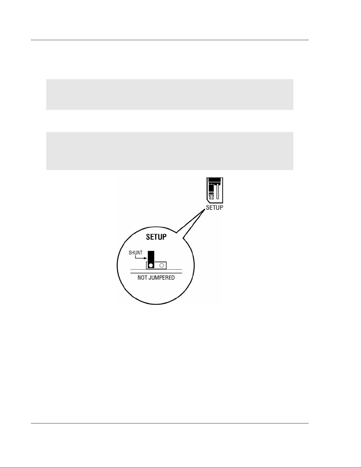
1.4 Setting Jumpers
Note: The Setup Jumper acts as "write protection" for the module's flash memory. In "write
protected" mode, the Setup pins are not connected, and the module's firmware cannot be
overwritten. Do not jumper the Setup pins together unless you are directed to do so by ProSoft
Technical Support.
Page 12 of 119 ProSoft Technology, Inc.
November 3, 2008
Page 13
Start Here MVI69-DNPSNET ♦ CompactLogix or MicroLogix Platform
Distributed Network Protocol Interface Module
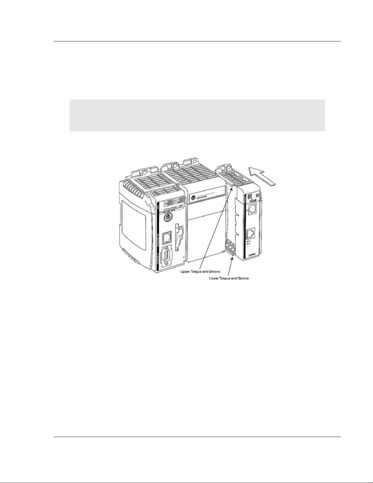
1.5 Install the Module in the Rack
This section describes how to install the module into a CompactLogix or
MicroLogix rack
Before you attempt to install the module, make sure that the bus lever of the
adjacent module is in the unlocked (fully right) position.
Warning: This module is not hot-swappable! Always remove power from the rack before
inserting or removing this module, or damage may result to the module, the processor, or other
connected devices.
1 Align the module using the upper and lower tongue-and-groove slots with the
adjacent module and slide forward in the direction of the arrow.
2 Move the module back along the tongue-and-groove slots until the bus
connectors on the MVI69 module and the adjacent module line up with each
other.
ProSoft Technology, Inc. Page 13 of 119
November 3, 2008
Page 14
MVI69-DNPSNET ♦ CompactLogix or MicroLogix Platform Start Here
Distributed Network Protocol Interface Module
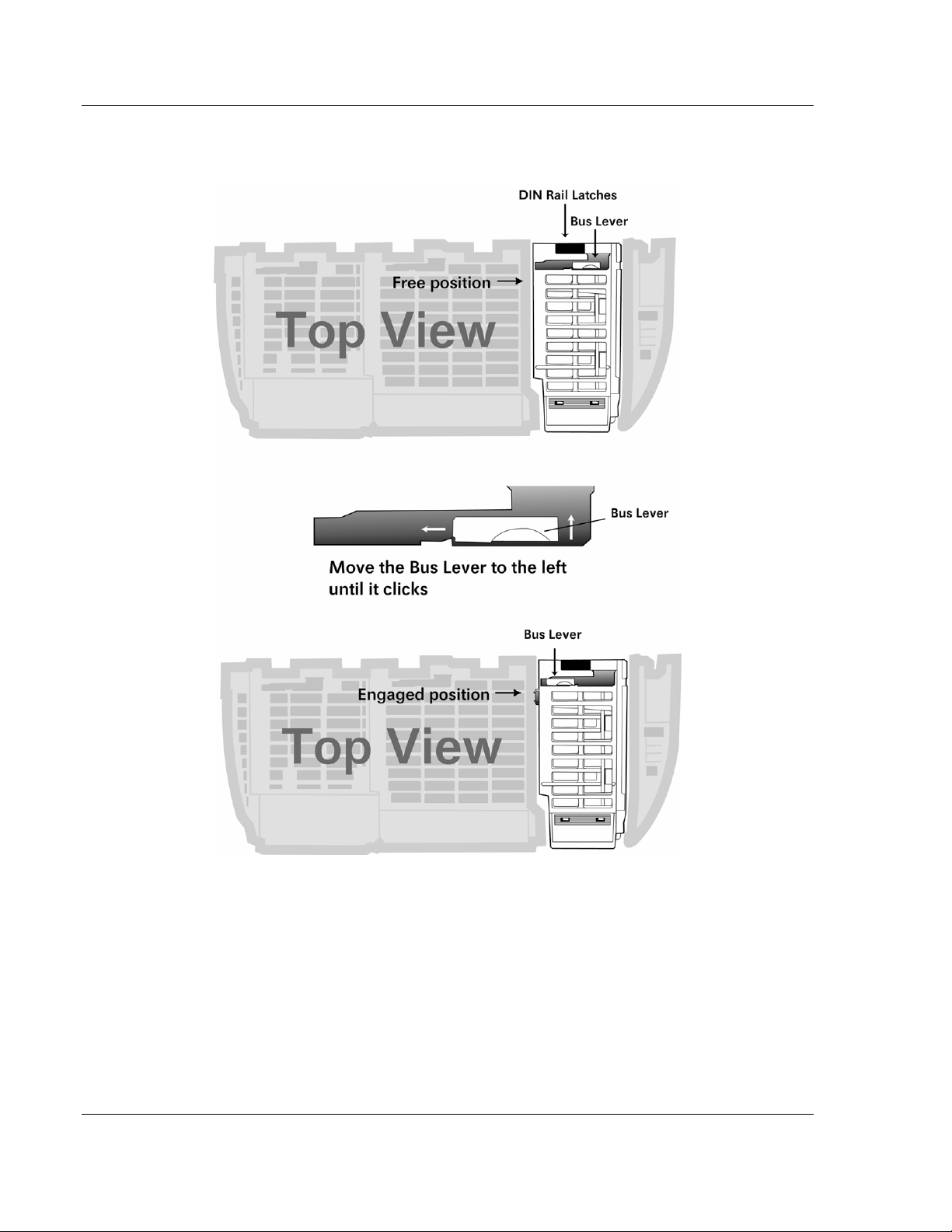
3 Push the module's bus lever back slightly to clear the positioning tab and
move it firmly to the left until it clicks. Ensure that it is locked firmly in place.
4 Close all DIN rail latches.
Page 14 of 119 ProSoft Technology, Inc.
November 3, 2008
Page 15
Start Here MVI69-DNPSNET ♦ CompactLogix or MicroLogix Platform
Distributed Network Protocol Interface Module
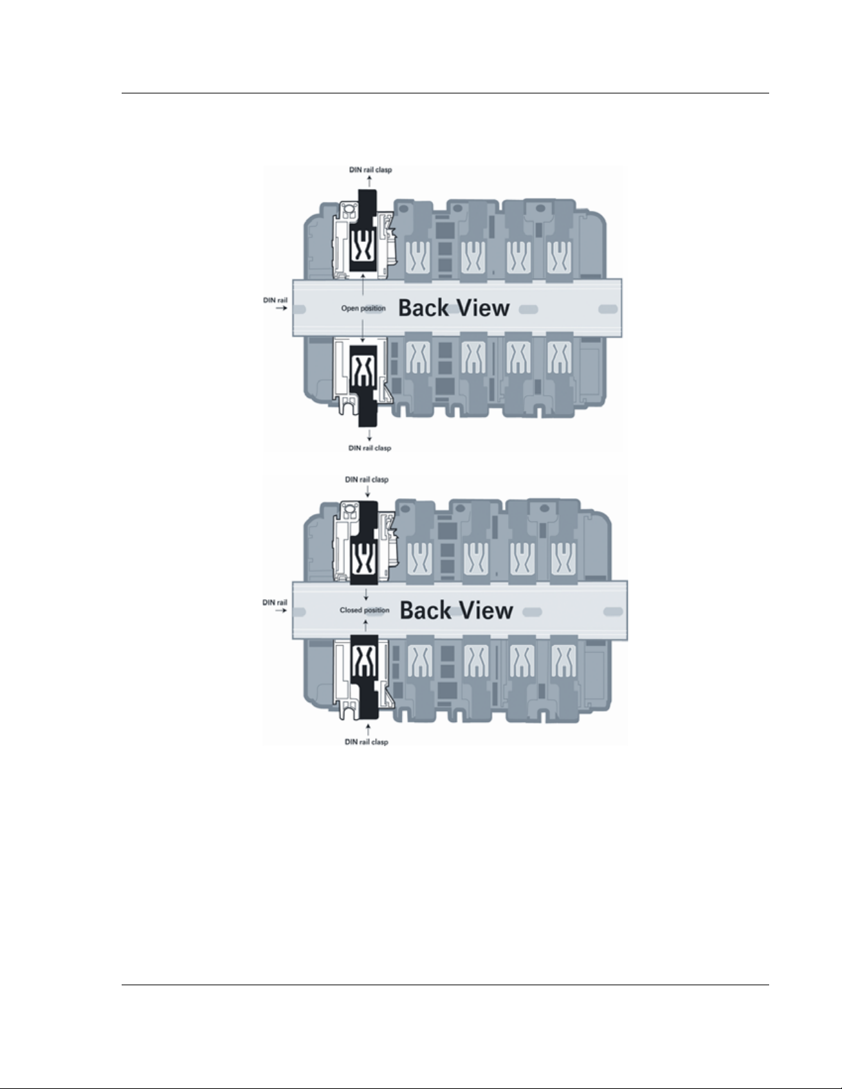
5 Press the DIN rail mounting area of the controller against the DIN rail. The
latches will momentarily open and lock into place.
ProSoft Technology, Inc. Page 15 of 119
November 3, 2008
Page 16
MVI69-DNPSNET ♦ CompactLogix or MicroLogix Platform Start Here
Distributed Network Protocol Interface Module
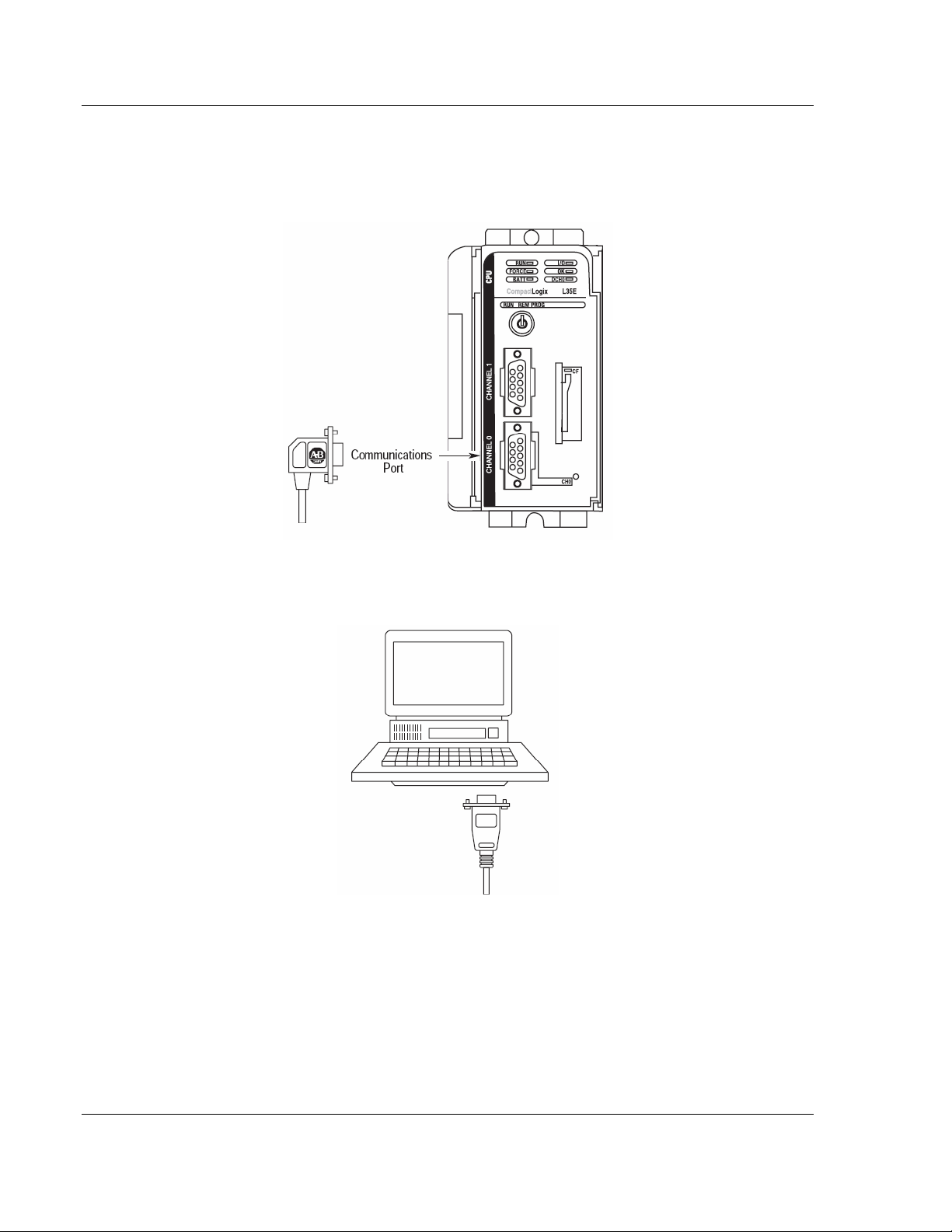
1.6 Connect your PC to the Processor
1 Connect the right-angle connector end of the cable to your controller at the
communications port.
2 Connect the straight connector end of the cable to the serial port on your
computer.
Page 16 of 119 ProSoft Technology, Inc.
November 3, 2008
Page 17
Start Here MVI69-DNPSNET ♦ CompactLogix or MicroLogix Platform
Distributed Network Protocol Interface Module
1.7 Download the Sample Program to the Processor
Important: For most applications, the sample program will work without modification.
Note: The key switch on the front of the CompactLogix processor must be in the REM position.
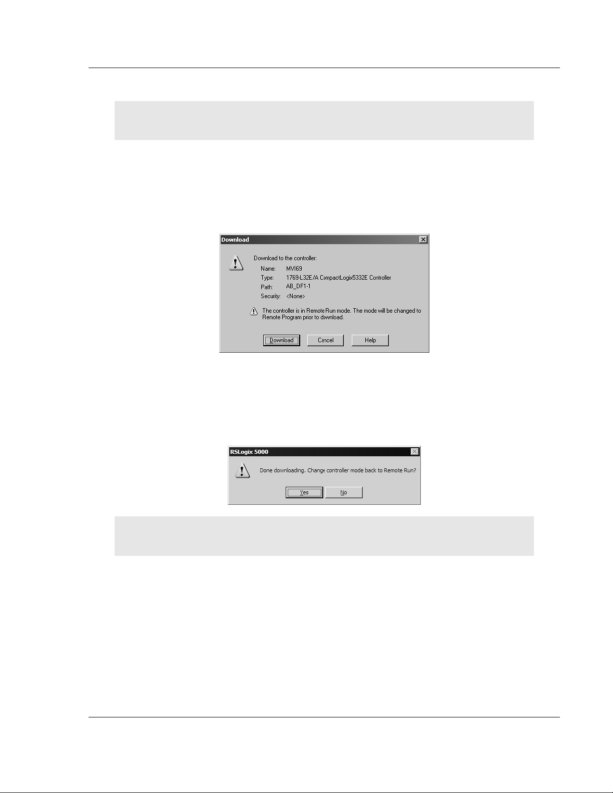
1 If you are not already online to the processor, open the Communications
menu, and then choose Download. RSLogix will establish communication
with the processor.
2 When communication is established, RSLogix will open a confirmation dialog
box. Click the Download button to transfer the sample program to the
processor.
3 RSLogix will compile the program and transfer it to the processor. This
process may take a few minutes.
4 When the download is complete, RSLogix will open another confirmation
dialog box. Click OK to switch the processor from Program mode to Run
mode.
Note: If you receive an error message during these steps, refer to your RSLogix documentation to
interpret and correct the error.
ProSoft Technology, Inc. Page 17 of 119
November 3, 2008
Page 18
MVI69-DNPSNET ♦ CompactLogix or MicroLogix Platform Start Here
Distributed Network Protocol Interface Module
1.7.1 Configuring RSLinx
If RSLogix is unable to establish communication with the processor, follow these steps:
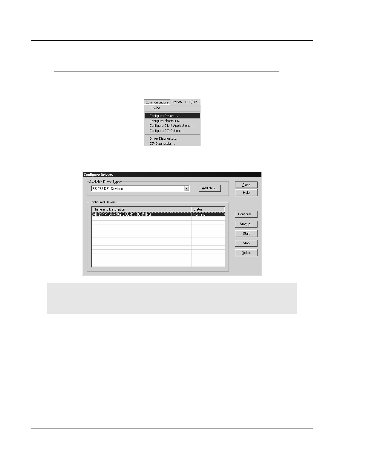
1 Open RSLinx.
2 Open the Communications menu, and choose Configure Drivers.
This action opens the Configure Drivers dialog box.
Note: If the list of configured drivers is blank, you must first choose and configure a driver from the
Available Driver Types list. The recommended driver type to choose for serial communication with
the processor is "RS-232 DF1 Devices".
Page 18 of 119 ProSoft Technology, Inc.
November 3, 2008
Page 19
Start Here MVI69-DNPSNET ♦ CompactLogix or MicroLogix Platform
Distributed Network Protocol Interface Module
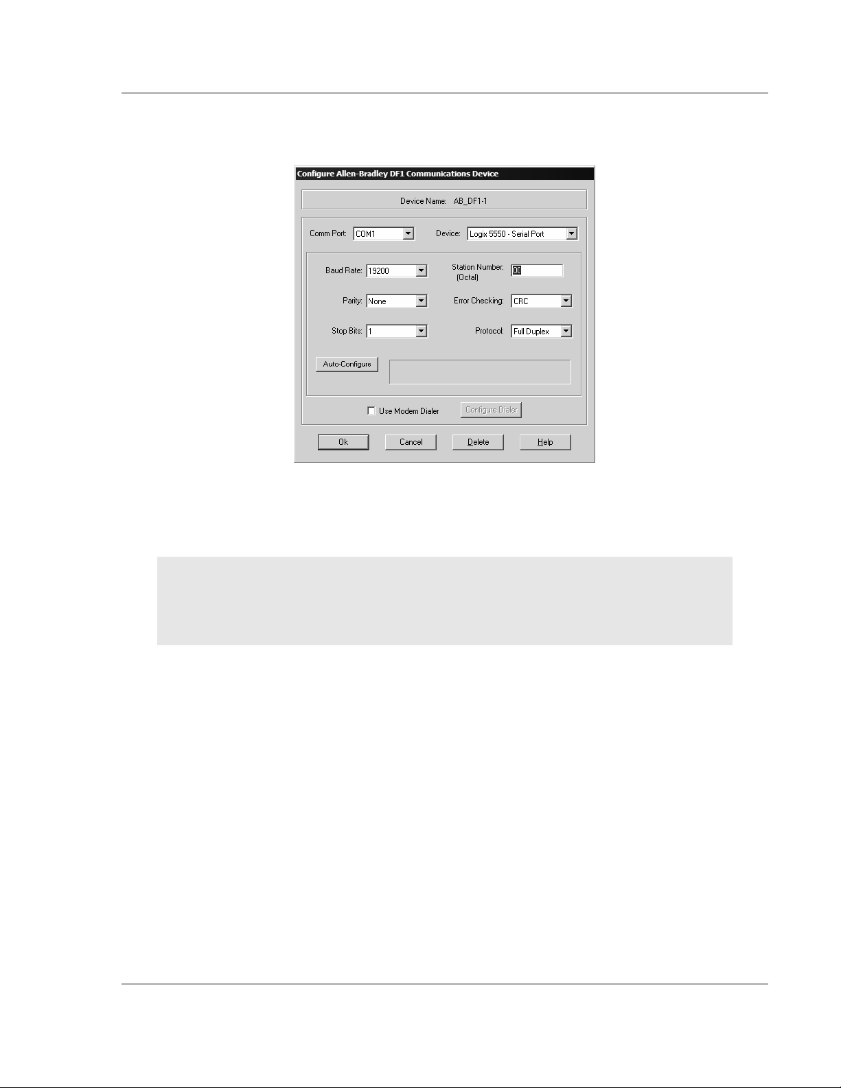
3 Click to select the driver, and then click Configure. This action opens the
Configure Allen-Bradley DF1 Communications Device dialog box.
4 Click the Auto-Configure button. RSLinx will attempt to configure your serial
port to work with the selected driver.
5 When you see the message "Auto Configuration Successful", click the OK
button to dismiss the dialog box.
Note: If the auto-configuration procedure fails, verify that the cables are connected correctly
between the processor and the serial port on your computer, and then try again. If you are still
unable to auto-configure the port, refer to your RSLinx documentation for further troubleshooting
steps.
ProSoft Technology, Inc. Page 19 of 119
November 3, 2008
Page 20
MVI69-DNPSNET ♦ CompactLogix or MicroLogix Platform Start Here
Distributed Network Protocol Interface Module
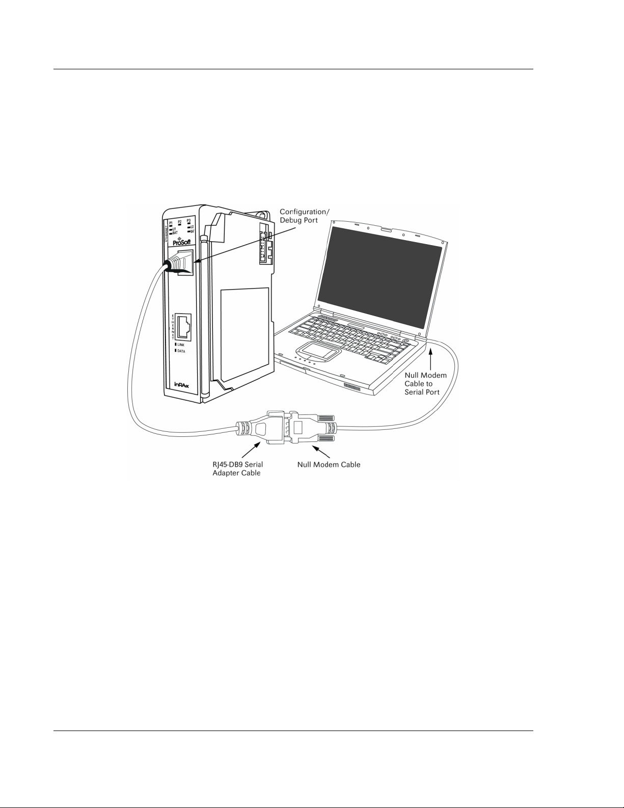
1.8 Connect your PC to the Module
With the module securely mounted, connect your PC to the Configuration/Debug
port using an RJ45-DB-9 Serial Adapter Cable and a Null Modem Cable.
1 Attach both cables as shown.
2 Insert the RJ45 cable connector into the Configuration/Debug port of the
module.
3 Attach the other end to the serial port on your PC or laptop.
Page 20 of 119 ProSoft Technology, Inc.
November 3, 2008
Page 21

Configuring the MVI69-DNPSNET Module MVI69-DNPSNET ♦ CompactLogix or MicroLogix Platform
Distributed Network Protocol Interface Module
2 Configuring the MVI69-DNPSNET Module
In This Chapter
ProSoft Configuration Builder................................................................21
[Backplane Configuration] .....................................................................26
[DNP ENET Slave] ................................................................................27
[DNP Slave Binary Inputs].....................................................................33
[DNP Slave Analog Inputs]....................................................................34
[DNP Slave Float Inputs].......................................................................34
[DNP ENET IP ADDRESSES]...............................................................35
Ethernet Configuration ..........................................................................35
Download the Project to the Module......................................................36
2.1 ProSoft Configuration Builder
ProSoft Configuration Builder (PCB) provides a quick and easy way to manage
module configuration files customized to meet your application needs. PCB is not
only a powerful solution for new configuration files, but also allows you to import
information from previously installed (known working) configurations to new
projects.
ProSoft Technology, Inc. Page 21 of 119
November 3, 2008
Page 22
MVI69-DNPSNET ♦ CompactLogix or MicroLogix Platform Configuring the MVI69-DNPSNET Module
Distributed Network Protocol Interface Module
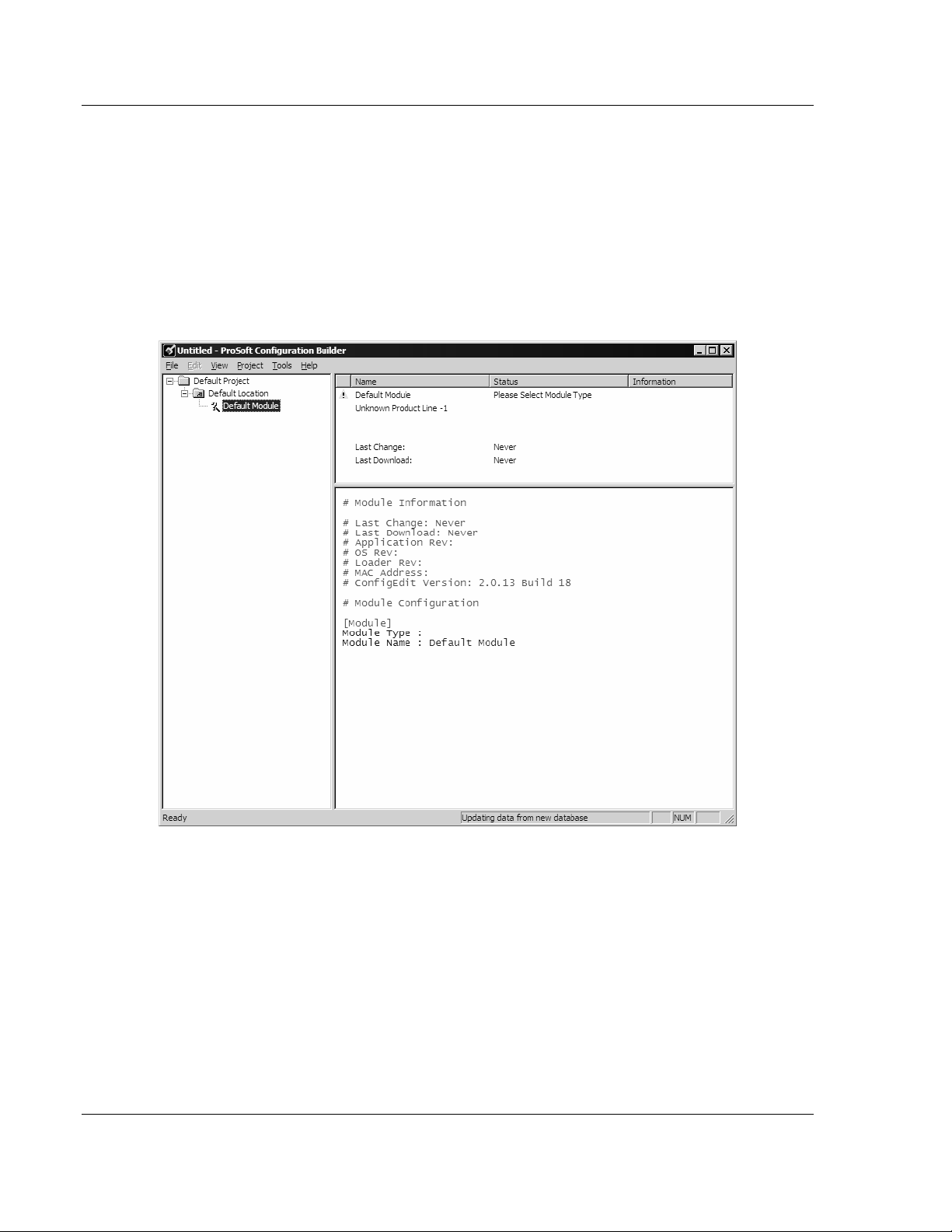
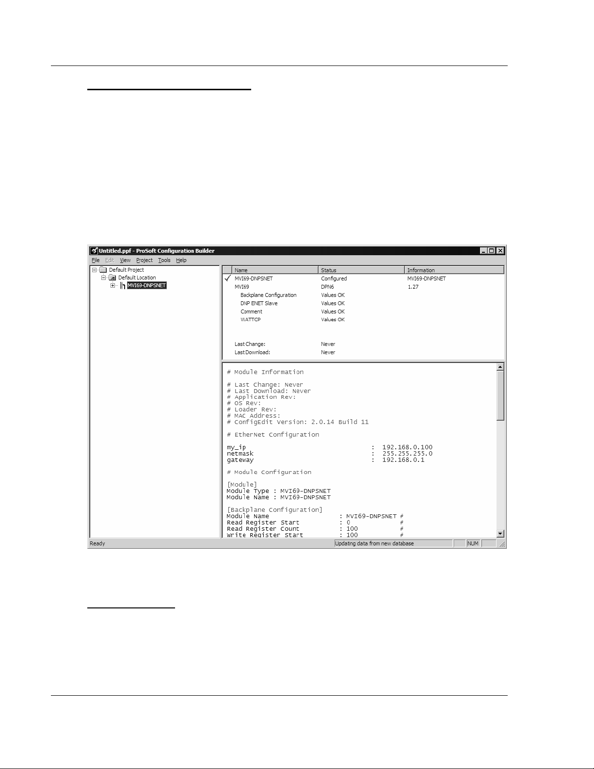
2.1.1 Set Up the Project
To begin, start ProSoft Configuration Builder. If you have used other Windows
configuration tools before, you will find the screen layout familiar. ProSoft
Configuration Builder's window consists of a tree view on the left, an information
pane and a configuration pane on the right side of the window. When you first
start ProSoft Configuration Builder, the tree view consists of folders for Default
Project and Default Location, with a Default Module in the Default Location
folder. The following illustration shows the ProSoft Configuration Builder window
with a new project.
Your first task is to add the MVI69-DNPSNET module to the project.
1 Use the mouse to select "Default Module" in the tree view, and then click the
right mouse button to open a shortcut menu.
Page 22 of 119 ProSoft Technology, Inc.
November 3, 2008
Page 23
Configuring the MVI69-DNPSNET Module MVI69-DNPSNET ♦ CompactLogix or MicroLogix Platform
Distributed Network Protocol Interface Module
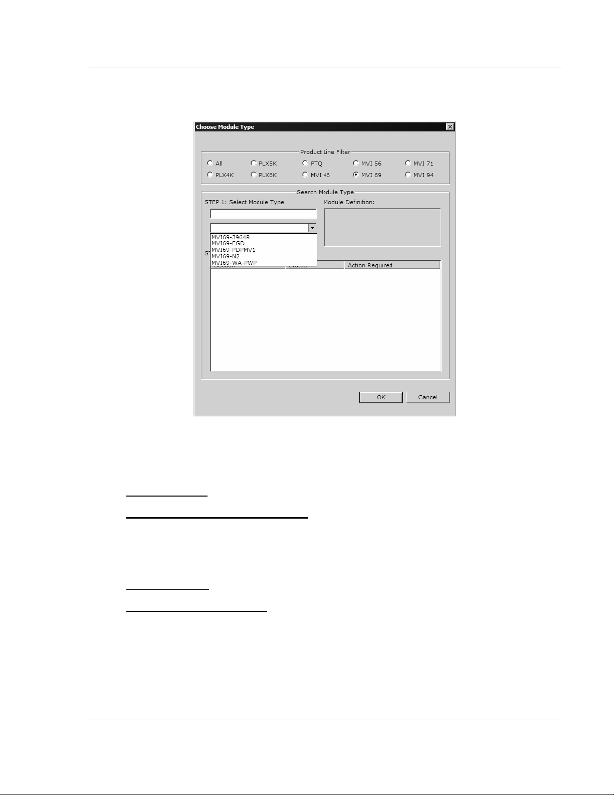
2 On the shortcut menu, choose "Choose Module Type". This action opens the
Choose Module Type dialog box.
3 In the Product Line Filter area of the dialog box, select MVI69. In the Select
Module Type dropdown list, select MVI69-DNPSNET, and then click OK to
save your settings and return to the ProSoft Configuration Builder window.
Adding a Project
To add a project to an existing project file:
1 Select the Default Project icon.
2 Choose Project from the Project menu, then choose Add Project. A new
project folder appears.
Adding a Module
To add a module to your project:
1 Double-click the Default Module icon to open the Choose Module Type dialog
box.
2 On the Choose Module Type dialog box, select the module type.
Or
1 Open the Project menu and choose Location.
2 On the Location menu, choose Add Module.
ProSoft Technology, Inc. Page 23 of 119
November 3, 2008
Page 24
MVI69-DNPSNET ♦ CompactLogix or MicroLogix Platform Configuring the MVI69-DNPSNET Module
Distributed Network Protocol Interface Module
To add a module to a different location:
1 Right-click the Location folder and choose Add Module. A new module icon
appears.
Or
1 Select the Location icon.
2 From the Project menu, select Location, then select Add Module.
2.1.2 Set Module Parameters
Notice that the contents of the information pane and the configuration pane
changed when you added the MVI69-DNPSNET module to the project.
At this time, you may wish to rename the "Default Project" and "Default Location"
folders in the tree view.
To rename an object:
1 Select the object, and then click the right mouse button to open a shortcut
menu. From the shortcut menu, choose Rename.
2 Type the name to assign to the object.
3 Click away from the object to save the new name.
Page 24 of 119 ProSoft Technology, Inc.
November 3, 2008
Page 25

Configuring the MVI69-DNPSNET Module MVI69-DNPSNET ♦ CompactLogix or MicroLogix Platform
Distributed Network Protocol Interface Module
Module Entries
To configure module parameters
1 Click on the plus sign next to the icon
to expand module
information.
2 Double-click the
icon to open the Edit dialog box.
3 To edit a parameter, select the parameter in the left pane and make your
changes in the right pane.
4 Click OK to save your changes.
Comment Entries
To add comments to your configuration file:
1 Click the plus sign to the left of the
icon to expand the Module
Comments.
2 Double-click the
icon. The Edit - Module Comment dialog
appears.
3 Enter your comment and click OK to save your changes.
Printing a Configuration File
To print a configuration file:
1 Select the Module icon, and then click the right mouse button to open a
shortcut menu.
2 On the shortcut menu, choose View Configuration. This action opens the
View Configuration window.
3 On the View Configuration window, open the File menu, and choose Print.
This action opens the Print dialog box.
4 On the Print dialog box, choose the printer to use from the dropdown list,
select printing options, and then click OK.
ProSoft Technology, Inc. Page 25 of 119
November 3, 2008
Page 26

MVI69-DNPSNET ♦ CompactLogix or MicroLogix Platform Configuring the MVI69-DNPSNET Module
Distributed Network Protocol Interface Module
2.2 [Backplane Configuration]
This section of the file describes the database setup and module level
parameters.
2.2.1 Module Name
0 to 80 characters
This parameter assigns a name to the module that can be viewed using the
configuration/debug port. Use this parameter to identify the module and the
configuration file.
2.2.2 Read Register Start
0 to 8899
This parameter specifies the starting register in the module where data will be
transferred from the module to the processor. Valid range for this parameter is 0
to 8899.
2.2.3 Read Register Count
0 to 8900
This parameter specifies the number of registers to be transferred from the
module to the processor. Valid entry for this parameter is 0 to 8900.
2.2.4 Write Register Start
0 to 8899
This parameter specifies the starting register in the module where the data will be
transferred from the processor to the module. Valid range for this parameter is 0
to 8899.
2.2.5 Write Register Count
0 to 8900
This parameter specifies the number of registers to transfer from the processor to
the module. Valid entry for this parameter is 0 to 8900.
2.2.6 Block Transfer Size
60, 120 or 240
This read-only parameter specifies the number of words in each block transferred
between the module and processor. Valid values for this parameter are 60, 120
and 240.
Page 26 of 119 ProSoft Technology, Inc.
November 3, 2008
Page 27

Configuring the MVI69-DNPSNET Module MVI69-DNPSNET ♦ CompactLogix or MicroLogix Platform
Distributed Network Protocol Interface Module
2.2.7 Failure Flag Count
0 to 65535
This parameter specifies the number of successive transfer errors that must
occur before the communication ports are shut down. If the parameter is set to 0,
the communication ports will continue to operate under all conditions. The value
range should be between 0 and 6900.
2.2.8 Error Offset
0 to 8899
This parameter specifies the register location in the module's database where
module status data will be stored. If a value less than 0 is entered, the data will
not be stored in the database. If the value specified is in the range of 0 to 8966,
the data will be placed in the modules database.
2.2.9 Initialize Output Data
Yes or No
This parameter determines if the output data for the module should be initialized
with values from the processor. If the value is set to N, the output data will be
initialized to 0. If the value is set to Y, the data will be initialized with data from
the processor.
2.3 [DNP ENET Slave]
This section provides information required to configure a slave application with
the module. Most entries contained within this section are self explanatory with
the possible exception of the Use IP List directive. This directive instructs the
module to verify the address of the received message and ignore the message if
it is not on our list of acceptable clients.
2.3.1 Internal Slave ID
0 to 65534
This is the DNP address for the module. All messages with this address received
from the master will be processed by the module.
2.3.2 Use IP List
Y or N
This parameter specifies if the IP address of the host connected to the system
will be validated. If the parameter is set to N, any host may connect to the unit. If
the parameter is set to Y, only hosts in the IP list will be permitted to connect to
the module. All other IP addresses will be ignored by the module and the module
will issue a RST to the TCP/IP connection.
ProSoft Technology, Inc. Page 27 of 119
November 3, 2008
Page 28

MVI69-DNPSNET ♦ CompactLogix or MicroLogix Platform Configuring the MVI69-DNPSNET Module
Distributed Network Protocol Interface Module
DNP Database Definition Note: The databases are in the memory of the module in this sequence
and are placed directly adjacent to each other. In other words when you change the size of a
database you must adjust the transfer commands to accommodate the new location.
2.3.3 Binary Inputs
0 to 500 words
This parameter specifies the number of digital input points to configure in the
DNP slave device based on a word count. The valid range is 0 to 500 words.
2.3.4 Analog Inputs
0 to 500 points
This parameter sets the number of analog input points to configure in the DNP
slave device. Each point will occupy a one-word area in the module memory.
2.3.5 Float Inputs
0 to 150
Number of floating-point input points to configure in the DNP slave device. Each
point will occupy a two-word area in the module memory.
2.3.6 Counters
0 to 250 points
This parameter sets the number of counter points to configure in the DNP slave
device. Each point will occupy a two-word area in the module memory. This
number corresponds to the number of frozen counters. The application maps the
counters to the frozen counters directly. Valid values are 0 to 250 points.
2.3.7 Binary Outputs
0 to 500 words
Number of digital output points to configure in the DNP slave device based on a
word count. Each word stores 16 points. Therefore, if the parameter is set to 2,
32 binary outputs will be defined for the application.
2.3.8 Analog Outputs
0 to 500 points
Number of analog output points to configure in the DNP slave device. Each point
will occupy a one word area in the module memory.
2.3.9 Float Outputs
0 to 150 points
Number of floating-point output points to configure in the DNP slave device. Each
point will occupy a two- word area in the module memory.
Page 28 of 119 ProSoft Technology, Inc.
November 3, 2008
Page 29

Configuring the MVI69-DNPSNET Module MVI69-DNPSNET ♦ CompactLogix or MicroLogix Platform
Distributed Network Protocol Interface Module
2.3.10 BI Class
0=disable, else 1 to 3
This parameter specifies the default class to be utilized for all the binary input
points in the DNP database that are not defined in the override list section.
2.3.11 AI Class
0=disable, else 1 to 3
This parameter specifies the default class to be utilized for all the analog input
points in the DNP database that are not defined in the override list section.
2.3.12 Float Class
0=disable, else 1 to 3
This parameter specifies the default class to be utilized for all the floating-point
input points in the DNP database that are not defined in the override list section.
2.3.13 AI Deadband
0 to 32767 data units
This value sets the global deadband for all analog input points. When the current
value for an analog input point is not within the deadband limit set based on the
last event for the point, an event will be generated.
2.3.14 Float Deadband
0 to 32767 data units
This parameter specifies the default deadband value assigned to all points not
defined in the override list for the floating-point input point type in the DNP
database.
2.3.15 Select/Operate Arm Time
1 to 65535 milliseconds
This parameter sets the time period after select command received in which
operate command will be performed. After the select command is received, the
operate command will only be honored if it arrives within this period of time. Valid
arm timeout values are 1 to 65535 milliseconds. This example shows the value
set to 2000 milliseconds.
2.3.16 Write Time Interval
0 to 1440 minutes
This parameter sets the time interval to set the need time IIN bit (0=never), which
will cause the master to write the time. Stored in milliseconds in the module
memory.
ProSoft Technology, Inc. Page 29 of 119
November 3, 2008
Page 30

MVI69-DNPSNET ♦ CompactLogix or MicroLogix Platform Configuring the MVI69-DNPSNET Module
Distributed Network Protocol Interface Module
2.3.17 App Layer Confirm Tout
1 to 65535 milliseconds
Event data contained in the last response may be sent again if not confirmed
within the millisecond time period set. If application layer confirms are used with
data link confirms, ensure that the application layer confirm timeout is set long
enough.
2.3.18 Unsolicited Response
Yes or No
This parameter is set if the slave unit will send unsolicited response messages. If
set to N, the slave will not send unsolicited responses. If set to Y, the slave will
send unsolicited responses.
2.3.19 Class 1 Unsol Resp Min
1 to 255 events
Minimum number of events in Class 1 required before an unsolicited response
will be generated.
2.3.20 Class 2 Unsol Resp Min
1 to 255 events
Minimum number of events in Class 2 required before an unsolicited response
will be generated.
2.3.21 Class 3 Unsol Resp Min
1 to 255 events
Minimum number of events in Class 3 required before an unsolicited response
will be generated.
2.3.22 Unsol Resp Delay
0 to 65535 milliseconds
Maximum number of 1 millisecond intervals to wait after an event occurs before
sending an unsolicited response message. If set to 0, only use minimum number
of events.
2.3.23 Uresp Master Address
0 to 65534
DNP destination address where unsolicited response messages are sent.
Page 30 of 119 ProSoft Technology, Inc.
November 3, 2008
Page 31

Configuring the MVI69-DNPSNET Module MVI69-DNPSNET ♦ CompactLogix or MicroLogix Platform
Distributed Network Protocol Interface Module
2.3.24 BI with Flag
Yes or No
This parameter determines which variation will be returned for object 1 when the
master requests variation 0. If the parameter is set to N, variation 1 will be
returned. If the parameter is set to Y, variation 2 will be returned.
Note: Flag will always be set for Online and cannot be changed through by the PLC or user
program. Only the default variation returned by the module will be affected by changing this
parameter.
2.3.25 BI Events Without Time
Yes or No
This parameter determines if the binary input events generated by the module
will include the date and time of the event. If the parameter is set to Yes, the
default is set to no time data. If the parameter is set to No, the default object will
include the time of the event.
2.3.26 AI with Flag
Yes or No
This parameter determines which variation will be returned for object 30 when
the master requests variation 0. If the parameter is set to N, variation 4 will be
returned. If the parameter is set to Y, variation 2 will be returned.
Note: Flag will always be set for Online and cannot be changed through by the PLC or user
program. Only the default variation returned by the module will be affected by changing this
parameter.
2.3.27 AI Events with Time
Yes or No
This parameter determines if the analog input events generated by the module
will include the date and time of the event. If the parameter is set to N, the default
is set to no time data. If the parameter is set to Y, the default object will include
the time of the event.
2.3.28 BO Without Flag
Yes or No
This parameter determines which variation will be returned for object 10 when
the master requests variation 0. If the parameter is set to N, variation 2 will be
returned. If the parameter is set to Y, variation 1 will be returned.
ProSoft Technology, Inc. Page 31 of 119
November 3, 2008
Page 32

MVI69-DNPSNET ♦ CompactLogix or MicroLogix Platform Configuring the MVI69-DNPSNET Module
Distributed Network Protocol Interface Module
2.3.29 Counter with Flag
Yes or No
This parameter determines which variation will be returned for object 20 when
the master requests variation 0. If the parameter is set to N, variation 5 will be
returned. If the parameter is set to Y, variation 1 will be returned.
Note: Flag will always be set for Online and cannot be changed through by the PLC or user
program. Only the default variation returned by the module will be affected by changing this
parameter.
2.3.30 Frozen Counter with Flag
Yes or No
This parameter determines which variation will be returned for object 21 when
the master requests variation 0. If the parameter is set to N, variation 9 will be
returned. If the parameter is set to Y, variation 1 will be returned.
Note: Flag will always be set for Online and cannot be changed through by the PLC or user
program. Only the default variation returned by the module will be affected by changing this
parameter.
2.3.31 Time Sync Before Events
Yes or No
This parameter determines if events are to be generated by the module before
the time synchronization from the master unit. If the parameter is set to N, events
will be generated irrespective of the module's time sync status. If the parameter
is set to Y, events will be generated only if the module's time is synchronized.
2.3.32 Use Trip/Close Single Point
Yes or No
If you set this parameter to Yes, Trip/Close events will function like Pulse On
operations. Only one bit will be reserved in the DNP BO database.
If you set this parameter to No, the dual-point relay control database (Trip/Close)
is overlaid on the DNP Binary Output database of the module. Each DNP point
index sent will have an offset of point index times 2 into the database. The first bit
of the dual-point relay control database will correspond to the close relay and the
second will correspond to the trip relay.
The bit definitions from control byte of CROB are as follows:
00 - Null (single bit control or select of Trip/Close
01 - Close relay
10 - Trip relay
11 - Invalid
Page 32 of 119 ProSoft Technology, Inc.
November 3, 2008
Page 33

Configuring the MVI69-DNPSNET Module MVI69-DNPSNET ♦ CompactLogix or MicroLogix Platform
Distributed Network Protocol Interface Module
If the operate command is used with the Null relay (00), the module will operate
on the point as single point control. The following table describes the module's
behavior:
Point Index in Command Point in Database Controlled
0 Bit 0 in BO database
10 Bit 10 in BO database
15 Bit 15 in BO database
If the operate command is used with the close relay selected, the module will
operate on the first bit of the two database bits associated with the point. The
following table describes the module's behavior when the close relay is selected:
Point Index in Command Point in Database Controlled
0 Bit 0 in BO database
1 Bit 2 in BO database
10 Bit 20 in BO database
15 Bit 30 in BO database
If the operate command is used with the trip relay selected, the module will
operate on the second bit of the two database bits associated with the point. The
following table describes the module's behavior when the trip relay is selected:
Point Index in Command Point in Database Controlled
0 Bit 1 in BO database
1 Bit 3 in BO database
10 Bit 21 in BO database
15 Bit 31 in BO database
It is important to note that the trip and close relays are linked in the module. If a
latch-on command is sent to the close relay its bit will be set and the associated
trip relay bit will be cleared.
Because the single-point and dual-point control database share the same
memory area, caution should be exercised to prevent control of one area by
another. This can be accomplished by careful design of the system. The dualpoint database could be isolated from the single-point database. For example,
DNP point index 0 to 9 could be used for the dual-point database and correspond
to bits 0 to 19. The single-point control points would then start at DNP point index
20 which corresponds to bit 20 of the database.
Using this technique, the MVI69-DNPSNET module will not require any
configuration for the new dual-point control, and the module will be backward
compatible for current customer applications.
2.4 [DNP Slave Binary Inputs]
This section of the configuration file overrides the Class 2 binary database points.
2.4.1 Point #
This is the information object address of the point.
ProSoft Technology, Inc. Page 33 of 119
November 3, 2008
Page 34

MVI69-DNPSNET ♦ CompactLogix or MicroLogix Platform Configuring the MVI69-DNPSNET Module
Distributed Network Protocol Interface Module
2.4.2 Class
Class 1 - Highest priority
Class 2 - Middle priority
Class 3 - Lowest priority
0 - Disable.
2.5 [DNP Slave Analog Inputs]
This area is to override the class (3) and deadband for the integer analog input
database. The point # is the offset from the start of the analog input database.
2.5.1 Point #
This is the information object address of the point.
2.5.2 Class
Class 1 - Highest priority
Class 2 - Middle priority
Class 3 - Lowest priority
0 - Disable.
2.5.3 Deadband
A range of values within which the module will avoid generating events.
2.6 [DNP Slave Float Inputs]
This area is to override the class (3) and deadband for the single float database.
The point # is not the address in the analog database, but is the offset from the
start of the single floating-point database.
2.6.1 Point #
This is the information object address of the point.
2.6.2 Class
Class 1 - Highest priority
Class 2 - Middle priority
Class 3 - Lowest priority
0 - Disable.
2.6.3 Deadband
A range of values within which the module will avoid generating events.
Page 34 of 119 ProSoft Technology, Inc.
November 3, 2008
Page 35

Configuring the MVI69-DNPSNET Module MVI69-DNPSNET ♦ CompactLogix or MicroLogix Platform
Distributed Network Protocol Interface Module
2.7 [DNP ENET IP ADDRESSES]
This section of the configuration file only applies if the directive labeled Use IP
List is set to Yes or Y. If Use IP List is enabled, the module will refuse to answer
a request unless the IP address of the client is listed in this section. This section
may contain no more then 10 addresses.
2.8 Ethernet Configuration
Use this procedure to configure the Ethernet settings for your module. You must
assign an IP address, subnet mask and gateway address. After you complete
this step, you can connect to the module with an Ethernet cable.
1 Determine the network settings for your module, with the help of your network
administrator if necessary. You will need the following information:
o IP address (fixed IP required) _____ . _____ . _____ . _____
o Subnet mask _____ . _____ . _____ . _____
2 Gateway address _____ . _____ . _____ . _____Click [+] to expand
the tree for the MVI69-DNPSNET module.
3 Double-click the Ethernet Configuration object. This action opens the Edit
dialog box.
4 Edit the values for my_ip, netmask (subnet mask) and gateway (default
gateway).
5 When you are finished editing, click OK to save your changes and return to
the ProSoft Configuration Builder window.
ProSoft Technology, Inc. Page 35 of 119
November 3, 2008
Page 36

MVI69-DNPSNET ♦ CompactLogix or MicroLogix Platform Configuring the MVI69-DNPSNET Module
Distributed Network Protocol Interface Module
2.9 Download the Project to the Module
In order for the module to use the settings you configured, you must download
(copy) the updated Project file from your PC to the module.
To Download the Project File
1 In the tree view in ProSoft Configuration Builder, click once to select the
MVI69-DNPSNET module.
2 Open the Project menu, and then choose Module / Download. The program
will scan your PC for a valid com port (this may take a few seconds). When
PCB has found a valid com port, the following dialog box will open.
3 Choose the com port to use from the dropdown list, and then click the
Download button.
The module will perform a platform check to read and load its new settings.
When the platform check is complete, the status bar in ProSoft Configuration
Builder will be updated with the message "Module Running".
Page 36 of 119 ProSoft Technology, Inc.
November 3, 2008
Page 37

Ladder Logic MVI69-DNPSNET ♦ CompactLogix or MicroLogix Platform
Distributed Network Protocol Interface Module
3 Ladder Logic
In This Chapter
Module Data Objects.............................................................................37
Adding the Module to an Existing CompactLogix Project......................41
Adding the Module to an Existing MicroLogix Project............................45
Ladder logic is required for application of the MVI69-DNPSNET module. Tasks
that must be handled by the ladder logic are module data transfer, special block
handling and status data receipt. Additionally, a power-up handler may be
needed to handle the initialization of the module's data and to clear any
processor fault conditions.
The sample ladder logic, on the ProSoft Solutions CD-ROM, is extensively
commented, to provide information on the purpose and function of each rung. For
most applications, the sample ladder will work without modification.
3.1 Module Data Objects
All data related to the MVI69-DNPSNET is stored in one user defined data type,
containing data transfer and status data, and the DNP datasets. Any time an
array's size is altered in the RSLogix 5000 software, all the data in the object can
be set to zero. Because the array sizes may need to be adjusted for the data
types in an application, the user defined data should be adjusted prior to the
module being placed in service (if the default configuration does not contain
enough data points for the application).
An instance of each data type is required before the module can be used. This is
accomplished by declaring variables of the data types in the Controller Tags Edit
Tags dialog box. Each object is discussed in the following topics.
3.1.1 DNPModuleDef Object
The DNPModuleDef object contains all the MVI69-DNPSNET module status data
and data transfer variables. The object has the following structure.
Name Data Type Description
Status DNPSlvStat
Data DNPData
CMDcontrolbits DNPCMDBits
ReadClock DNPClock
WriteClock DNPClock
BI_Events DNPBIEvntBlk
AI_Events DNPAIEvntBLK
BP DNPBackplane
ProSoft Technology, Inc. Page 37 of 119
November 3, 2008
Page 38

MVI69-DNPSNET ♦ CompactLogix or MicroLogix Platform Ladder Logic
Distributed Network Protocol Interface Module
Each of these object types are discussed in the following topics:
DNPSlvStat
This object holds the module status information transferred with each read data
block transferred from the module. The structure of the object is shown in the
following example:
Name Data Type Description
Scan_Cnt INT Program Scan Counter
Product_Name SINT[4] Product Code
Rev_Level SINT[4] Revision
Op_Sys SINT[4] Operating system revision
Run_Number SINT[4] Run number
Blk_Rd_Count INT Number of block read transfers
Blk_Wr_Count INT Number of block write transfers
Blk_Parse_Cnt INT Number of blocks parsed by module
Blk_Err INT Number of block errors
Rx_Frames INT Number of frames received for this unit
Tx_Frames INT Number of frames transmitted for this unit
Rx_Total INT Number of frames received
Sync_err INT Sync error count
Overrun_err INT Overrun error count
len_err INT Length error count
CRC_err INT CRC error count
Overflow_err INT Overflow error count
Seq_err INT Sequence error count
Addrs_err INT Address error count
BI_Events INT Number of binary events generated
BI_Queue INT Number of binar y events in q ueue
AI_Events INT Number of analog input events
AI_Queue INT Number of analog input events in queue
FL_Queue INT Float Input Event Count in Buffer
Reserved INT Reserved
Bad_func_err INT Number of bad function code error count
Ukn_Obj_err INT Unknown Object error count
Range_err INT Range error count
App_Overflow INT Number of application level overflow errors
Multi_Frame_err INT Multi-frame error count
UDP_Rx_Count INT UDP Recieve Count
UDP_Tx_Count INT UDP transmit Count
Unsol_error INT Unsolicited Error Count
State_Value INT State Value
TCP_ST_value INT TCP Socket State Value
Page 38 of 119 ProSoft Technology, Inc.
November 3, 2008
Page 39

Ladder Logic MVI69-DNPSNET ♦ CompactLogix or MicroLogix Platform
Distributed Network Protocol Interface Module
Name Data Type Description
UDP_ST_Value INT UDP Socket State Value
Busywithmsg INT DNP Busy with Message State
App_Fragm INT Application fragment
Tx_frame_ST INT Transmit frame State
TCP_msg_len INT TCP message length
UDP_msg_len INT UDP message length
Port_Tx_St INT Port Transmit state
Free_Mem DINT Free Memory
This information is important as it can be used to view the "health" of the module.
If the module is not communicating, examine the object to help find the problem.
Additionally, you should use the configuration/debug port on the module to
confirm that the desired configuration of the module is implemented.
DNPBackplane Object
The DNPBackplane Object stores the variables required for backplane data
transfer between the module and the processor. The structure of the object is
displayed in the following example:
Name Data Type Description
BlockTransferSize INT
LastRead INT Index of last read block
LastWrite INT Index of last write block
BlockIndex INT Computed block offset for data table
ReadData INT[240] Buffer File for data Read from Module
WriteData INT[240] Buffer File for data Write from Module.
3.1.2 DNPData Object
The DNPData object stores all the data for an MVI69-DNPSNET module.
Contained within the object is an array for each data type. The array sizes are set
to match the configuration set for the module. If multiple MVI69-DNPSNET
modules are used within a rack, a copy of this structure may have to be made to
permit each module to have its own database sizes. Ladder logic is required to
transfer the data in this structure between the module and the processor. The
structure of the object is shown in the following example:
Name Data Type Description
DNP_BI INT[20] Number of DNP BI data words
DNP_AI INT[40] Number of DNP AI data words
DNP_FLTI REAL[20] Number of DNP Float Input Points
DNP_Cntr DINT[10] Number of DNP counter double-words
DNP_BO INT[40] Number of DNP BO data words
DNP_AO INT[40] Number of DNP AO data words
DNP_FLTO REAL[20] Number of DNP Float Output points
ProSoft Technology, Inc. Page 39 of 119
November 3, 2008
Page 40

MVI69-DNPSNET ♦ CompactLogix or MicroLogix Platform Ladder Logic
Distributed Network Protocol Interface Module
3.1.3 Special Objects
These objects utilize some of the advanced features the module provides. If your
application does not require the object, then you need not declare an instance of
the object. Each of the objects and associated function are discussed in the
following topics.
DNP_BI_Event Object
The DNP_BI_Event object stores the information for eleven binary input events
to be sent from the processor to the module in a command block 9958. The
structure shown in the following example contains all the parameters required for
binary input events.
Name Data Type Description
EventCount INT Event Count
SeqCounter INT Sequence Counter
EventData DNPBIEvntData[11]
DataPoint INT DNP Binary Input Data Point
Day SINT Day
MonthState SINT Month and State Bit (state is MSB)
Minutes SINT Minutes
Hour SINT Hours
SecMsecond INT
Year INT Year
Formatted: Bits 0-9 = Milliseconds, bits 10 to 15
= Seconds
3.1.4 DNP_AI_Event Object
The DNP_AI_Event object stores the information for nine analog input events to
be sent from the processor to the module in a command block 9959. The
structure shown in the following example contains all the parameters required for
analog input events.
Name Data Type Description
EventCount INT Event Count
SeqCounter INT Sequence Counter
EventData DNPAIEvntData[9] Event Data Points
AIDataPoint INT DNP Analog Input Data Point
AIvalue INT DNP Analog Input Value
Day SINT Day
Month SINT Month
Minutes SINT Minutes
Hour SINT Hour
SecMsec INT
Year INT Year
Formatted, bits 0 to 9 = Milliseconds, bits 1015 = seconds
Page 40 of 119 ProSoft Technology, Inc.
November 3, 2008
Page 41

Ladder Logic MVI69-DNPSNET ♦ CompactLogix or MicroLogix Platform
Distributed Network Protocol Interface Module
3.2 Adding the Module to an Existing CompactLogix Project
Important: The MVI69-DNPSNET module has a power supply distance rating of 2 (L43 and L45
installations on first 2 slots of 1769 bus)
If you are installing and configuring the module with a CompactLogix processor,
follow these steps. If you are using a MicroLogix processor, refer to the next
section.
1 Add the MVI69-DNPSNET module to the project. Right-click the mouse
button on the I/O Configuration option in the Controller Organization window
to display a pop-up menu. Select the New Module option from the I/O
Configuration menu.
ProSoft Technology, Inc. Page 41 of 119
November 3, 2008
Page 42

MVI69-DNPSNET ♦ CompactLogix or MicroLogix Platform Ladder Logic
Distributed Network Protocol Interface Module
This action opens the following dialog box:
2 Select the 1769-Module (Generic 1769 Module) from the list and click OK.
3 Enter the Name, Description and Slot options for your application, using the
values in the illustration above. You must select the Comm Format as Data INT in the dialog box, otherwise the module will not communicate over the
backplane of the CompactLogix rack.
4 Configure the Connection Parameters to match to the Block Transfer Size
parameter in the configuration file. Use the values in the table corresponding
with the block transfer size you configured.
Block Transfer Size = 60
Field Recommended Value
Type 1769-MODULE Generic 1769 Module
Parent Local
Name MVI69
Description MVI69 Application Module
Comm Format Data - INT
Page 42 of 119 ProSoft Technology, Inc.
November 3, 2008
Page 43

Ladder Logic MVI69-DNPSNET ♦ CompactLogix or MicroLogix Platform
Distributed Network Protocol Interface Module
Block Transfer Size = 60
Field Recommended Value
Slot The slot number in the rack where the module is installed
Input Assembly Instance 101
Input Size 62
Output Assembly Instance 100
Output Size 61
Configuration Assembly Instance 102
Configuration Size 0
Block Transfer Size = 120
Field Recommended Value
Type 1769-MODULE Generic 1769 Module
Parent Local
Name MVI69
Description MVI69 Application Module
Comm Format Data - INT
Slot The slot number in the rack where the module is installed
Input Assembly Instance 101
Input Size 122
Output Assembly Instance 100
Output Size 121
Configuration Assembly Instance 102
Configuration Size 0
Block Transfer Size = 240
Field Recommended Value
Type 1769-MODULE Generic 1769 Module
Parent Local
Name MVI69
Description MVI69 Application Module
Comm Format Data - INT
Slot The slot number in the rack where the module is installed
Input Assembly Instance 101
Input Size 242
Output Assembly Instance 100
Output Size 241
Configuration Assembly Instance 102
Configuration Size 0
ProSoft Technology, Inc. Page 43 of 119
November 3, 2008
Page 44

MVI69-DNPSNET ♦ CompactLogix or MicroLogix Platform Ladder Logic
Distributed Network Protocol Interface Module
5 Click Next to continue.
6 Select the Request Packet Interval value for scanning the I/O on the module.
This value represents the minimum frequency the module will handle
scheduled events. This value should not be set to less than 1 millisecond.
Values between 1 and 10 milliseconds should work with most applications.
7 Save the module. Click OK to dismiss the dialog box. The Controller
Organization window now displays the module's presence. The following
illustration shows the Controller Organization window:
8 Copy the Controller Tags from the sample program.
9 Copy the User Defined Data Types from the sample program.
10 Copy the Ladder Rungs from the sample program.
11 Save and Download the new application to the controller and place the
processor in run mode.
Page 44 of 119 ProSoft Technology, Inc.
November 3, 2008
Page 45

Ladder Logic MVI69-DNPSNET ♦ CompactLogix or MicroLogix Platform
Distributed Network Protocol Interface Module
3.3 Adding the Module to an Existing MicroLogix Project
If you are installing and configuring the module with a MicroLogix processor,
follow these steps. If you are using a CompactLogix processor, refer to the
previous section.
The first step in setting up the processor ladder file is to define the I/O type
module to the system. Start RSLogix 500, and follow these steps:
1 In RSLogix, open your existing application, or start a new application,
depending on your requirements.
2 Double-click the I/O Configuration icon located in the Controller folder in the
project tree. This action opens the I/O Configuration dialog box.
3 On the I/O Configuration dialog box, select "Other - Requires I/O Card Type
ID" at the bottom of the list in the right pane, and then double-click to open
the Module dialog box.
ProSoft Technology, Inc. Page 45 of 119
November 3, 2008
Page 46

MVI69-DNPSNET ♦ CompactLogix or MicroLogix Platform Ladder Logic
Distributed Network Protocol Interface Module
4 Enter the values shown in the following illustration to define the module
correctly for the MicroLogix processor, and then click OK to save your
configuration.
The input words and output words parameter will depend on the Block
Transfer Size parameter you specify in the configuration file. Use the values
from the following table.
Block Transfer Size Input Words Output Words
60 62 61
120 122 121
240 242 241
5 Click Next to continue.
6 After completing the module setup, the I/O configuration dialog box will
display the module's presence.
The last step is to add the ladder logic. If you are using the example ladder logic,
adjust the ladder to fit your application. Refer to the example Ladder Logic
section in this manual.
Download the new application to the controller and place the processor in run
mode. If you encounter errors, refer to Diagnostics and Troubleshooting (page
47) for information on how to connect to the module's Config/Debug port to use
its troubleshooting features.
Page 46 of 119 ProSoft Technology, Inc.
November 3, 2008
Page 47

Diagnostics and Troubleshooting MVI69-DNPSNET ♦ CompactLogix or MicroLogix Platform
Distributed Network Protocol Interface Module
4 Diagnostics and Troubleshooting
In This Chapter
Reading Status Data from the Module ..................................................47
LED Status Indicators............................................................................58
The module provides information on diagnostics and troubleshooting in the
following forms:
Status data values are transferred from the module to the processor.
Data contained in the module can be viewed through the
Configuration/Debug port attached to a terminal emulator.
LED status indicators on the front of the module provide information on the
module's status.
4.1 Reading Status Data from the Module
The MVI69-DNPSNET module provides the status data in each read block. This
data can also be located in the module's database. For a complete listing of the
status data object, refer to the Module Set Up section.
4.1.1 Required Hardware
You can connect directly from your computer's serial port to the serial port on the
module to view configuration information, perform maintenance, and send
(upload) or receive (download) configuration files.
ProSoft Technology recommends the following minimum hardware to connect
your computer to the module:
80486 based processor (Pentium preferred)
1 megabyte of memory
At least one UART hardware-based serial communications port available.
USB-based virtual UART systems (USB to serial port adapters) often do not
function reliably, especially during binary file transfers, such as when
uploading/downloading configuration files or module firmware upgrades.
A null modem serial cable.
4.1.2 The Configuration/Debug Menu
The Configuration and Debug menu for this module is arranged as a tree
structure, with the Main Menu at the top of the tree, and one or more sub-menus
for each menu command. The first menu you see when you connect to the
module is the Main menu.
ProSoft Technology, Inc. Page 47 of 119
November 3, 2008
Page 48

MVI69-DNPSNET ♦ CompactLogix or MicroLogix Platform Diagnostics and Troubleshooting
Distributed Network Protocol Interface Module
Because this is a text-based menu system, you enter commands by typing the
command letter from your computer keyboard in the diagnostic window in
ProSoft Configuration Builder (PCB). The module does not respond to mouse
movements or clicks. The command executes as soon as you press the
command letter — you do not need to press [Enter]. When you type a command
letter, a new screen will be displayed in your terminal application.
Using the Diagnostic Window in ProSoft Configuration Builder
To connect to the module's Configuration/Debug serial port:
1 Start PCB program with the application file to be tested. Right click over the
module icon.
2 On the shortcut menu, choose Diagnostics.
Page 48 of 119 ProSoft Technology, Inc.
November 3, 2008
Page 49

Diagnostics and Troubleshooting MVI69-DNPSNET ♦ CompactLogix or MicroLogix Platform
Distributed Network Protocol Interface Module
3 This action opens the Diagnostics dialog box. Press "?" to display the Main
Menu.
Important: The illustrations of configuration/debug menus in this section are intended as a general
guide, and may not exactly match the configuration/debug menus in your own module.
If there is no response from the module, follow these steps:
1 Verify that the null modem cable is connected properly between your
computer's serial port and the module. A regular serial cable will not work.
2 On computers with more than one serial port, verify that your communication
program is connected to the same port that is connected to the module.
If you are still not able to establish a connection, contact ProSoft Technology for
assistance.
Navigation
All of the sub-menus for this module contain commands to redisplay the menu or
return to the previous menu. You can always return from a sub-menu to the next
higher menu by pressing [M] on your keyboard.
The organization of the menu structure is represented in simplified form in the
following illustration:
ProSoft Technology, Inc. Page 49 of 119
November 3, 2008
Page 50

MVI69-DNPSNET ♦ CompactLogix or MicroLogix Platform Diagnostics and Troubleshooting
Distributed Network Protocol Interface Module
The remainder of this section shows you the menus available for this module,
and briefly discusses the commands available to you.
Keystrokes
The keyboard commands on these menus are almost always non-case sensitive.
You can enter most commands in lower case or capital letters.
The menus use a few special characters ([?], [-], [+], [@]) that must be entered
exactly as shown. Some of these characters will require you to use the [Shift],
[Ctrl] or [Alt] keys to enter them correctly. For example, on US English
keyboards, enter the [?] command as [Shift][/].
Also, take care to distinguish capital letter [I] from lower case letter [l] (L) and
number [1]; likewise for capital letter [O] and number [0]. Although these
characters look nearly the same on the screen, they perform different actions on
the module.
4.1.3 Main Menu
When you first connect to the module from your computer, your terminal screen
will be blank. To activate the main menu, press the [?] key on your computer's
keyboard. If the module is connected properly, the following menu will appear on
your terminal screen:
Caution: Some of the commands available to you from this menu are designed for advanced
debugging and system testing only, and can cause the module to stop communicating with the
processor or with other devices, resulting in potential data loss or other failures. Only use these
commands if you are specifically directed to do so by ProSoft Technology Technical Support staff.
Some of these command keys are not listed on the menu, but are active nevertheless. Please be
careful when pressing keys so that you do not accidentally execute an unwanted command.
Viewing Block Transfer Statistics
Press [B] from the Main Menu to view the Block Transfer Statistics screen.
Use this command to display the configuration and statistics of the backplane
data transfer operations between the module and the processor. The information
on this screen can help determine if there are communication problems between
the processor and the module.
Page 50 of 119 ProSoft Technology, Inc.
November 3, 2008
Page 51

Diagnostics and Troubleshooting MVI69-DNPSNET ♦ CompactLogix or MicroLogix Platform
Distributed Network Protocol Interface Module
Tip: To determine the number of blocks transferred each second, mark the numbers displayed at a
specific time. Then some seconds later activate the command again. Subtract the previous
numbers from the current numbers and divide by the quantity of seconds passed between the two
readings.
Viewing Module Configuration
Press [C] to view the Module Configuration screen.
Use this command to display the current configuration and statistics for the
module.
Opening the Database Menu
Press [D] to open the Database View menu. Use this menu command to view the
current contents of the module's database.
Opening the DNP Menu
Press [I] from the Main Menu to open the DNP Menu. This menu allows you to
view all data associated with the DNP Server driver. For more information about
the commands on this menu, refer to DNP Menu (page 52).
Receiving the Configuration File
Press [R] to download (receive) the current configuration file from the module.
For more information on receiving and sending configuration files, please see
Uploading and Downloading the Configuration File.
Sending the Configuration File
Press [S] to upload (send) an updated configuration file to the module. For more
information on receiving and sending configuration files, please see Uploading
and Downloading the Configuration File.
Viewing Version Information
Press [V] to view Version information for the module.
Use this command to view the current version of the software for the module, as
well as other important values. You may be asked to provide this information
when calling for technical support on the product.
Values at the bottom of the display are important in determining module
operation. The Program Scan Counter value is incremented each time a
module's program cycle is complete.
Tip: Repeat this command at one-second intervals to determine the frequency of program
execution.
ProSoft Technology, Inc. Page 51 of 119
November 3, 2008
Page 52

MVI69-DNPSNET ♦ CompactLogix or MicroLogix Platform Diagnostics and Troubleshooting
Distributed Network Protocol Interface Module
Warm Booting the Module
Caution: Some of the commands available to you from this menu are designed for advanced
debugging and system testing only, and can cause the module to stop communicating with the
processor or with other devices, resulting in potential data loss or other failures. Only use these
commands if you are specifically directed to do so by ProSoft Technology Technical Support staff.
Some of these command keys are not listed on the menu, but are active nevertheless. Please be
careful when pressing keys so that you do not accidentally execute an unwanted command.
Press [W] from the Main Menu to warm boot (restart) the module. This command
will cause the program to exit and reload, refreshing configuration parameters
that must be set on program initialization. Only use this command if you must
force the module to re-boot.
Opening the Network Menu
Press [@] to open the network menu. The network menu allows you to send,
receive and view the WATTCP.CFG file that contains the IP, gateway and other
network specification information. You can find more information about the
commands on this menu in the Network Menu (page 57) section.
Exiting the Program
Caution: Some of the commands available to you from this menu are designed for advanced
debugging and system testing only, and can cause the module to stop communicating with the
processor or with other devices, resulting in potential data loss or other failures. Only use these
commands if you are specifically directed to do so by ProSoft Technology Technical Support staff.
Some of these command keys are not listed on the menu, but are active nevertheless. Please be
careful when pressing keys so that you do not accidentally execute an unwanted command.
Press [Esc] to restart the module and force all drivers to be loaded. The module
will use the configuration stored in the module's Flash ROM to configure the
module.
4.1.4 DNP Menu
This opens the DNP menu. After the option is selected, press the '?' key to
display the menu and the following is displayed:
Each option on the menu is discussed in the following topics.
Viewing DNP Set Up & Pointers
Press [B] to display the memory allocation and the database setup parameters.
Page 52 of 119 ProSoft Technology, Inc.
November 3, 2008
Page 53

Diagnostics and Troubleshooting MVI69-DNPSNET ♦ CompactLogix or MicroLogix Platform
Distributed Network Protocol Interface Module
Viewing DNP Configuration
Press [C] to displays the configuration information for the server. Use this
command to confirm that the module is configured as desired. If any parameter is
not set correctly, adjust the configuration file and download the altered file to the
unit.
Opening the DNP Database View Menu
Press [D] to open the DNP Database View menu. Use this command to display
the database associated with each data type.
Viewing a List of Valid Hosts
Press [I] to view the list of IP addresses from which the module will accept
connections This list is only used if the module configuration parameter, Use IP
List, is set to a value other than 0.
Returning to the Main Menu
Press [M] to return to the Main Menu.
Viewing DNP Communication Status
Press [1] to view DNP Communication Status. Use this command to view the
communication status data for the DNP driver.
Viewing TCP Socket Status
Press [2] to view the status of the TCP socket in the module. After selecting the
option, the following is displayed:
The parameters displayed have the following definitions:
Rx Count - Number of messages received on TCP socket
Tx Count - Number of messages transmitted on TCP socket
Tx State - 0=not transmitting, 1=transmitting
TCP State - Value used for TCP/IP socket state machine
Busy Flag - 0=not busy, 1=TCP has control of DNP server, 2=UDP has control
of DNP server, 3=Unsolicited message being sent
App Frame - 0=no application data frame data, 1=application data available
Tx Frame - 0=Data link level frame ready to send, 1=Data link level message not
ready to send
ProSoft Technology, Inc. Page 53 of 119
November 3, 2008
Page 54

MVI69-DNPSNET ♦ CompactLogix or MicroLogix Platform Diagnostics and Troubleshooting
Distributed Network Protocol Interface Module
Packet Length - Length of message left to process
Viewing UDP Socket Status
Press [3] to view the status of the UDP socket in the module. After selecting the
option, the following is displayed:
The parameters displayed have the following definitions:
Rx Count - Number of messages received on UDP socket
Tx Count - Number of messages transmitted on UDP socket
Tx State - 0=not transmitting, 1=transmitting
TCP State - Value used for UDP/IP socket state machine
Busy Flag - 0=not busy, 1=TCP has control of DNP server, 2=UDP has control
of DNP server, 3=Unsolicited message being sent
App Frame - 0=no application data frame data, 1=application data available
Tx Frame - 0=Data link level frame ready to send, 1=Data link level message not
ready to send
Packet Length - Length of message left to process
Page 54 of 119 ProSoft Technology, Inc.
November 3, 2008
Page 55

Diagnostics and Troubleshooting MVI69-DNPSNET ♦ CompactLogix or MicroLogix Platform
Distributed Network Protocol Interface Module
4.1.5 Database View Menu
Press [D] from the Main Menu to open the Database View menu. Use this menu
command to view the current contents of the module's database. Press [?] to
view a list of commands available on this menu.
Viewing Register Pages
To view sets of register pages, use the keys described below:
Command Description
[0]
[1]
[2]
Display registers 0 to 99
Display registers 1000 to 1099
Display registers 2000 to 2099
And so on. The total number of register pages available to view depends on your
module's configuration.
Displaying the Current Page of Registers Again
This screen displays the current page of 100 registers in the database.
ProSoft Technology, Inc. Page 55 of 119
November 3, 2008
Page 56

MVI69-DNPSNET ♦ CompactLogix or MicroLogix Platform Diagnostics and Troubleshooting
Distributed Network Protocol Interface Module
Moving Back Through 5 Pages of Registers
Press [-] from the Database View menu to skip back to the previous 500
registers of data.
Viewing the Previous 100 Registers of Data
Press [P] from the Database View menu to display the previous 100 registers of
data.
Skipping 500 Registers of Data
Hold down [Shift] and press [=] to skip forward to the next 500 registers of data.
Viewing the Next 100 Registers of Data
Press [N] from the Database View menu to select and display the next 100
registers of data.
Viewing Data in Decimal Format
Press [D] to display the data on the current page in decimal format.
Viewing Data in Hexadecimal Format
Press [H] to display the data on the current page in hexadecimal format.
Viewing Data in Floating Point Format
Press [F] from the Database View menu. Use this command to display the data
on the current page in floating point format. The program assumes that the
values are aligned on even register boundaries. If floating-point values are not
aligned as such, they are not displayed properly.
Viewing Data in ASCII (Text) Format
Press [A] to display the data on the current page in ASCII format. This is useful
for regions of the database that contain ASCII data.
Returning to the Main Menu
Press [M] to return to the Main Menu.
Page 56 of 119 ProSoft Technology, Inc.
November 3, 2008
Page 57

Diagnostics and Troubleshooting MVI69-DNPSNET ♦ CompactLogix or MicroLogix Platform
Distributed Network Protocol Interface Module
4.1.6 Network Menu
The network menu allows you to send, receive and view the WATTCP.CFG file
that contains the IP and gateway addresses, and other network specification
information.
Transferring WATTCP.CFG to the module
Press [R] to transfer a new WATTCP.CFG file from the PC to the module. Use
this command to change the network configuration for the module (for example,
the module's IP address).
Press [Y] to confirm the file transfer, and then follow the instructions on the
terminal screen to complete the file transfer process.
Transferring WATTCP.CFG to the PC
Press [S] to transfer the WATTCP.CFG file from the module to your PC.
Press [Y] to confirm the file transfer, and then follow the instructions on the
terminal screen to complete the file transfer process.
After the file has been successfully transferred, you can open and edit the file to
change the module's network configuration.
Viewing the WATTCP.CFG file on the module
Press [V] to view the module's WATTCP.CFG file. Use this command to confirm
the module's current network settings.
Returning to the Main Menu
Press [M] to return to the Main Menu.
ProSoft Technology, Inc. Page 57 of 119
November 3, 2008
Page 58

MVI69-DNPSNET ♦ CompactLogix or MicroLogix Platform Diagnostics and Troubleshooting
Distributed Network Protocol Interface Module
4.2 LED Status Indicators
The LEDs indicate the module's operating status as follows:
Module Color Status Indication
CFG Green
EP Not Used
BP ACT Amber
OK Red/
Green
On
Off No data is being transferred on the Configuration/Debug port.
Off The MVI69-DNPSNET is working normally. APP Amber
On
On
Off
Off
Green The module is operating normally.
Red
Off The battery voltage is OK and functioning. BAT Red
On
Data is being transferred between the module and a remote
terminal using the Configuration/Debug port.
The MVI69-DNPSNET module program has recognized a
communication error on one of its DNP ports.
The LED is on when the module is performing a write
operation on the backplane.
The LED is off when the module is performing a read
operation on the backplane. Under normal operation, the LED
should blink rapidly on and off.
The card is not receiving any power and is not securely
plugged into the rack.
The program has detected an error or is being configured. If
the LED remains red for over 10 seconds, the program has
probably halted. Remove the card from the rack and re-insert
the card to restart the module's program.
The battery voltage is low or battery is not present. Allow
battery to charge by keeping module plugged into rack for 24
hours. If BAT LED still does not go off, contact ProSoft
Technology, as this is not a user serviceable item.
If the APP, BP ACT and OK LEDs blink at a rate of every one-second, this
indicates a serious problem with the module. Call ProSoft Technology support to
arrange for repairs.
4.2.1 Ethernet LED Indicators
LED State Description
Off No activity on the port. Data
Green Flash The port is either actively transmitting or receiving data.
Off No connection to hub or network is detected. Link
Green Solid
Page 58 of 119 ProSoft Technology, Inc.
Connected to hub or network correctly. This is the normal
operating state.
November 3, 2008
Page 59

Diagnostics and Troubleshooting MVI69-DNPSNET ♦ CompactLogix or MicroLogix Platform
Distributed Network Protocol Interface Module
4.2.2 Clearing a Fault Condition
Typically, if the OK LED on the front of the module turns red for more than ten
seconds, a hardware problem has been detected in the module, or the program
has exited.
To clear the condition, follow these steps:
1 Turn off power to the rack
2 Remove the card from the rack
3 Verify that all jumpers are set correctly
4 If the module requires a Compact Flash card, verify that the card is installed
correctly
5 Re-insert the card in the rack and turn the power back on
6 Verify the configuration data being transferred to the module from the
CompactLogix or MicroLogix processor.
If the module's OK LED does not turn green, verify that the module is inserted
completely into the rack. If this does not cure the problem, contact ProSoft
Technology Support.
4.2.3 Troubleshooting
Use the following troubleshooting steps if you encounter problems when the
module is powered up. If these steps do not resolve your problem, please contact
ProSoft Technology Technical Support.
Processor Errors
Problem Description Steps to take
Processor Fault
Processor I/O LED
flashes
Verify that the module is plugged into the slot that has been configured
for the module.
Verify that the slot in the rack configuration has been set up correctly in
the ladder logic.
This indicates a problem with backplane communications. Verify that all
modules in the rack are configured in the ladder logic.
Module Errors
Problem Description Steps to take
BP ACT LED remains
off or blinks slowly
OK LED remains red
This indicates that backplane transfer operations are failing. Connect to
the module's Configuration/Debug port to check this.
To establish backplane communications, verify the following items:
The processor is in Run mode.
The backplane driver is loaded in the module.
The module is configured for read and write block data transfer.
The ladder logic handles all read and write block situations.
The module is configured in the processor.
The program has halted or a critical error has occurred. Connect to the
Configuration/Debug port to see if the module is running. If the program
has halted, turn off power to the rack, remove the card from the rack and
re-insert the card in the rack, and then restore power to the rack.
ProSoft Technology, Inc. Page 59 of 119
November 3, 2008
Page 60

MVI69-DNPSNET ♦ CompactLogix or MicroLogix Platform Diagnostics and Troubleshooting
Distributed Network Protocol Interface Module
4.2.4 Error Status Table
The program maintains an error/status table that is transferred to the processor
in each read block. Ladder logic should be programmed to accept this block of
data and place it in the module's controller tag. You can use the error/status data
to determine the "health" of the module.
The data in the block is structured as shown in the following table.
Word Variable Name Description
0 Scan Counter
1 to 2 Product Name (ASCII)
3 to 4 Revision (ASCII)
5 to 6
7 to 8
9 Read Block Co unt
10 Write Block Count
11 Parse Block Count
12 Block number error
13
14
15
16
17
18
19
Operating System Revision
(ASCII)
Production Run Number
(ASCII)
DNP Slave Port total
number of message frames
received by slave
DNP Slave Port total
number of response
message frames sent from
slave
DNP Slave Port total
number of message frames
seen by slave
DNP Slave synchronization
error count (Physical Layer
Error)
DNP Slave overrun error
count (Physical Layer
Error)
DNP Slave length error
count (Physical Layer
Error)
DNP Slave bad CRC error
(Data Link Layer Error)
Program scan counter incremented each time the
program loop is executed.
These two words contain the product name of the
module in ASCII format.
These two words contain the product revision level of the
firmware in ASCII format.
These two words contain the module's internal operating
system revision level in ASCII format.
These two words contain the production 'batch' number
for the particular chip in the module in ASCII format.
Total number of blocks transferred from the module to
the processor.
Total number of blocks transferred from the processor to
the module.
Total number of blocks parsed by the module that were
received from the processor.
Number of BTW requests that resulted in an incorrect
BTW identification code.
This value represents the total number of message
frames that have matched this slaves address on this
port. This count includes message frames which the
slave may or may not be able to parse and respond.
This value represents the number of good (non-error)
responses that the slave has sent to the master on this
port. The presumption is that if the slave is responding,
the message was good. Note: This is a frame count.
This value represents the total number of message
frames received by the slave, regardless of the slave
address.
This value counts the number of times a sync error
occurs. The error occurs when extra bytes are received
before the start bytes (0x05 and 0x64) are received.
This value counts the number of times the overrun error
occurs. This error occurs when the mainline Data Link
Layer routine cannot read the data received on the
communication port before it is overwritten.
This value counts the number of times an invalid length
byte is received. If the length of the message does not
match the length value in the message, this error occurs.
This value counts the number of times a bad CRC value
is received in a message.
Page 60 of 119 ProSoft Technology, Inc.
November 3, 2008
Page 61

Diagnostics and Troubleshooting MVI69-DNPSNET ♦ CompactLogix or MicroLogix Platform
Distributed Network Protocol Interface Module
Word Variable Name Description
20
21
22
23
24
25
26
27
28 Reserved Future Use
29
30
31
32
33
34 UDP Receive Count Number of UDP messages received
35 UDP Transmit Count Number of UDP messages transmitted
36 Unsolicited Error Count
37 State Value
38 TCP Socket State Value State machine value for the TCP socket
39 UDP Socket State Value State machine value for the UDP socket
40
41 Application Fragment Application fragmentation fla g/counter
DNP Slave user data
overflow error (Transport
Layer Error)
DNP Slave sequence error
(Transport Layer Error)
DNP Slave address error
(Transport Layer Error)
DNP Slave Binary Input
Event count
DNP Slave Binary Input
Event count in buffer
DNP Slave Analog Input
Event count
DNP Slave Analog Input
Event count in buffer
DNP Slave Float Input
Event count in buffer
DNP Slave bad function
code error (Application
Layer Error)
DNP Slave object unknown
error (Application Layer
Error)
DNP Slave out of range
error (Application Layer
Error)
DNP Slave message
overflow error (Application
Layer Error)
DNP Slave multi-frame
message from DNP Master
error (Application Layer
Error)
DNP Busy With Message
State
This value counts the number of times the application
layer receives a message fragment buffer which is too
small.
This value counts the number of times the sequence
numbers of multi-frame request fragments do not
increment correctly.
This value counts the number of times the source
addresses contained in a multi-frame request fragments
do not match.
This value contains the total number of binary input
events which have occurred.
This value represents the number of binary input events
which are waiting to be sent to the master.
This value contains the total number of analog input
events which have occurred.
This value represents the number of analog input events
which are waiting to be sent to the master.
This value represents the number of float input events
which are waiting to be sent to the master.
This value counts the number of times a bad function
code for a selected object/variation is received by the
slave device.
This value counts the number of times a request for an
unsupported object is received by the slave device.
This value counts the number of times a parameter in the
qualifier, range or data field is not valid or out of range.
This value counts the number of times an application
response message from the slave is too long to transmit.
This value counts the number of times the slave receives
a multi-frame message from the master. The application
does not support multi-frame master messages.
Number of failures when trying to send unsolicited event
data
This variable has a value of 0 if there is not a message
being sent and 1 if a message is being sent.
Socket busy state -1=TCP socket not connected, 0=TCP
or UDP not processing message, 1 or 3 = TCP
processing message, and 2=UDP socket processing
message.
ProSoft Technology, Inc. Page 61 of 119
November 3, 2008
Page 62

MVI69-DNPSNET ♦ CompactLogix or MicroLogix Platform Diagnostics and Troubleshooting
Distributed Network Protocol Interface Module
Word Variable Name Description
42 Transmit Frame State Transmit Frame State
43 TCP Message Length
44 UDP Message Length Bytes received on the UDP port for the current message.
45 Port TX State
46 Free Memory LSB Free memory in module
47 Free Memory MSB
Bytes Received on the TCP port for the current
message.
This variable has a value of 0 if there is not a message
being sent and 1 if a message is being sent.
Page 62 of 119 ProSoft Technology, Inc.
November 3, 2008
Page 63

Reference MVI69-DNPSNET ♦ CompactLogix or MicroLogix Platform
Distributed Network Protocol Interface Module
5 Reference
In This Chapter
Product Specifications...........................................................................63
Functional Overview..............................................................................65
MVI69-DNPSNET Application Design...................................................79
Cable Connections................................................................................93
MVI69-DNPSNET Status Data..............................................................96
MVI69-DNPSNET Module.....................................................................99
Device Profile ......................................................................................100
DNP Subset Definition.........................................................................101
Event Size Computation......................................................................107
5.1 Product Specifications
The MVI69 DNP 3.0 Server over Ethernet Communications Module supports the
implementation of the DNP 3.0 (Distributed Network Protocol) over Ethernet,
allowing CompactLogix processors to easily communicate with host systems
supporting the protocol. The module supports DNP Subset Level 2 features and
some Level 3 features.
The module supports DNP subset level 2 features and some Level 3 features.
The MVI69-DNPSNET module acts as an input/output module between the DNP
Ethernet network and the CompactLogix backplane. The data transfer from the
CompactLogix processor is asynchronous from the actions on the DNP network.
Databases are defined in the module to house the data required by the protocol.
5.1.1 General Specifications
Single Slot - 1769 backplane compatible
The module is recognized as an Input/Output module and has access to
processor memory for data transfer between processor and module
Ladder Logic is used for data transfer between module and processor.
Sample ladder file included.
Configuration data obtained from configuration text file downloaded to
module. Sample configuration file included.
Supports all CompactLogix processors: L20/L23/L30/L31/L32/L35, L43 and
L45 (L43 and L45 supported with RSLogix 5000 v16.03 or later)
Also supports MicroLogix 1500 LRP
ProSoft Technology, Inc. Page 63 of 119
November 3, 2008
Page 64

MVI69-DNPSNET ♦ CompactLogix or MicroLogix Platform Reference
Distributed Network Protocol Interface Module
5.1.2 Hardware Specifications
Specification Description
Dimensions Standard 1769 Single-slot module
Current Load
Operating Temp. 0 to 60°C (32 to 140°F)
Storage Temp. -40 to 85°C (-40 to 185°F)
Relative Humidity 5 to 95% (non-condensing)
LED Indicators
CFG Port (CFG)
App Port (Ethernet modules)
Shipped with Unit
800 mA max@ 5 VDC
Power supply distance rating of 2 (L43 and L45
installations on first 2 slots of 1769 bus)
Power and Module Status
Application Status
CFG Port Activity
Ethernet Port Activity
Error Status
RJ45 (DB-9M with supplied cable)
RS-232 only
No hardware handshaking
10/100 Base-T Ethernet compatible interface
Electrical Isolation 1500 V rms at 50 Hz to 60 Hz for 60 s,
applied as specified in section 5.3.2 of IEC 60950: 1991
Ethernet Broadcast Storm Resiliency = less than or equal
to 5000 [ARP] frames-per-second and less than or equal
to 5 minutes duration
RJ45 to DB-9M cables for each port
6-foot RS-232 configuration Cable
5.1.3 Functional Specifications
The MVI69-DNPSNET module accepts DNP commands to control and monitor
the data stored in the DNP databases. This data is passed between the module
and the CompactLogix processor over the backplane for use in user applications.
DNP databases to house data for the slave port supporting the following
maximum point counts
o Binary input: 8000 points (500 words)
o Binary output: 8000 points (500 words)
o Counter: 250 (500 words)
o Analog input: 500 words
o Analog output: 500 words
o Float input: 150 points (300 words)
o Float output: 150 points (300 words)
User-definable module memory usage up to maximum point counts
Data movement between module using Input/Output image
Ethernet port supporting both TCP and UDP over Ethernet
Supports DNP 3.0 in a level 2 implementation
Supports sending of input event data from the ladder to the module
Supports time synchronization from/to processor
Configurable via text file
Status and error information
All data in the DNP slave is contained in user-defined files
Page 64 of 119 ProSoft Technology, Inc.
November 3, 2008
Page 65

Reference MVI69-DNPSNET ♦ CompactLogix or MicroLogix Platform
Distributed Network Protocol Interface Module
5.2 Functional Overview
This section provides an overview of how the MVI69-DNPSNET module transfers
data using the DNPSNET protocol. You should understand the important
concepts in this chapter before you begin installing and configuring the module.
The DNPSNET protocol driver exists as a single service port (DNPSNET port
20000) implementation that supports a single TCP port connection and multiple
UDP ports on a TCP/IP Ethernet network. The DNPSNET port operates as a
server, supporting the DNP 3.0 protocol in a Level 2 implementation using the
DNP User Group recommended extension for use on LAN/WAN. This is
published in "Transporting DNP V3.00 over Local and Wide Area Networks",
December 15, 1998 by the DNP Users Group and is available on the Internet at
http://www.dnp.org.
5.2.1 General Concepts
The following discussion explains several concepts that are important for
understanding the operation of the MVI69-DNPSNET module.
Module Power Up
On power up the module begins performing the following logical functions:
1 Initialize hardware components
2 Install packet driver for Ethernet network interface and TCP/IP stack
o Initialize CompactLogix or MicroLogix backplane driver
o Test and clear all RAM
o Initialize the serial communication ports
3 Read configuration file from Compact Flash Disk
4 Enable Slave Driver
After the module has received the configuration, the module will begin
communicating with other nodes on the network, depending on the configuration.
ProSoft Technology, Inc. Page 65 of 119
November 3, 2008
Page 66

MVI69-DNPSNET ♦ CompactLogix or MicroLogix Platform Reference
Distributed Network Protocol Interface Module
Main Logic Loop
Upon completing the power up configuration process, the module enters an
infinite loop that performs the functions shown in the following diagram.
Backplane Data Transfer
The MVI69-DNPSNET module communicates directly over the CompactLogix or
MicroLogix backplane. Data is paged between the module and the CompactLogix
or MicroLogix processor across the backplane using the module's input and
output images. The update frequency of the images is determined by the
scheduled scan rate defined by the user for the module and the communication
load on the module. Typical updates are in the range of 1 to 10 milliseconds.
This bi-directional transference of data is accomplished by the module filling in
data in the module's input image to send to the processor. Data in the input
image is placed in the Controller Tags in the processor by the ladder logic. The
input image for the module can be set to 62, 122 or 242 words. This large data
area permits fast throughput of data between the module and the processor.
The processor inserts data to the module's output image to transfer to the
module. The module's program extracts the data and places it in the module's
internal database. The output image for the module can be set to 61, 121 or 241
words. This large data area permits fast throughput of data from the processor to
the module.
Page 66 of 119 ProSoft Technology, Inc.
November 3, 2008
Page 67

Reference MVI69-DNPSNET ♦ CompactLogix or MicroLogix Platform
Distributed Network Protocol Interface Module
The following illustration shows the data transfer method used to move data
between the CompactLogix or MicroLogix processor, the MVI69-DNPSNET
module and the DNP Network.
All data transferred between the module and the processor over the backplane is
through the input and output images. Ladder logic must be written in the
CompactLogix or MicroLogix processor to interface the input and output image
data with data defined in the Controller Tags. All data used by the module is
stored in its internal databases. These databases are defined as a virtual DNP
data tables with addresses from 0 to the maximum number of points for each
data type. The following illustration shows the layout of the databases:
DATA AREA
DNP DATA
FROZEN DATA FROZEN COUNTER DATA
LAST VALUE DATA
EVENT DATA
BINARY INPUTS
ANALOG INPUTS
FLOAT INPUTS
COUNTER DATA
BINARY OUTPUTS
ANALOG OUTPUTS
FLOAT OUTPUTS
BINARY INPUTS
ANALOG INPUTS
FLOAT INPUTS
BINARY INPUT EVENTS
ANALOG INPUT EVENTS
FLOAT INPUT EVENTS
ProSoft Technology, Inc. Page 67 of 119
November 3, 2008
Page 68

MVI69-DNPSNET ♦ CompactLogix or MicroLogix Platform Reference
Distributed Network Protocol Interface Module
Data contained in this database is paged through the input and output images by
coordination of the CompactLogix or MicroLogix ladder logic and the MVI69DNPSNET module's program. Up to 248 words of data can be transferred from
the module to the processor at a time. Up to 247 words of data can be
transferred from the processor to the module.
Each block transferred from the module to the processor or from the processor to
the module contains a block identification code that describes the content of the
block.
The following table defines the blocks used by this module:
Block Number Function/Description
0 or -1 Dummy Blocks : Used by module when no data is to be transferred
1 to 150 DNP Data blocks
1000 to 1149 Output initialization blocks
9250 Status Data Block
9958 PLC Binary Input Event data
9959 PLC Ana log Input Event Data
9970 Set PLC time using module's DNP time
9971 Set module's time using PLC time
9998 W arm Boot Request from PLC (Block contains no data)
9999 Cold Boot Request from PLC (Block contains no data)
Blocks 1 to 150 transfer data between the module and the processor. Blocks
1000 to 1149 are utilized to transfer the initial output databases (binary and
analog output data) from the processor to the module at startup. Blocks 9958 to
9999 are used for command control of the module. Each group of blocks are
discussed in the following topics.
Normal Data Transfer
Normal data transfer includes the paging of the user data found in the module's
internal databases between the module and the controller. These data are
transferred through read (input image) and write (output image) blocks. Refer to
the Module Set Up section for a description of the data objects used with the
blocks and the ladder logic required. Each data block transferred between the
module and the processor has a specific block identification code that defines the
data set contained in the block. The following illustration shows the direction of
movement of the DNP data types between the module and the processor:
DNP MEMORY
WRITE BLOCK FROM
PROCESSOR
WRITE BLOCK FROM
PROCESSOR
READ BLOCK FROM
MODULE
READ BLOCK FROM
MODULE
DIGITAL INPUT DATA
ANALOG INPUT DATA
FLOAT INPUT DATA
COUNTER DATA
BINARY OUTPUT DATA
ANALOG OUTPUT DATA
FLOAT OUTPUT DATA
FROZEN COUNTER, LAST
VALUE AND EVENT DATA
The structure and function of each block is described in the following topics:
Page 68 of 119 ProSoft Technology, Inc.
November 3, 2008
Page 69

Reference MVI69-DNPSNET ♦ CompactLogix or MicroLogix Platform
Distributed Network Protocol Interface Module
Read Block
These blocks of data transfer information from the module to the CompactLogix
processor. The structure of the input image used to transfer this data is shown
below:
Offset Description
0 Read Block ID
1 Write Block ID
2 to n Read Data
where
n = 60, 120, or 240 depending on the Block Transfer Size parameter (refer to the configuration file).
The Read Block ID is an index value used to determine the location of where the
data will be placed in the CompactLogix or MicroLogix processor controller tag
array of module read data. The number of data words per transfer depends on
the configured Block Transfer Size parameter in the configuration file (possible
values are 60, 120, or 240).
The Write Block ID associated with the block requests data from the
CompactLogix or MicroLogix processor. Under normal, program operation, the
module sequentially sends read blocks and requests write blocks. For example, if
three read and two write blocks are used with the application, the sequence will
be as follows:
R1W1
R2W2 R3W1 R1W2 R2W1 R3W2 R1W1
This sequence will continue until interrupted by other write block numbers sent by
the controller or by a command request from a node on the DNP network or
operator control through the module's Configuration/Debug port.
The following example shows a typical backplane communication application.
Note: This example for reference only
Assume that the backplane parameters are configured as follows:
Read Register Start: 0
Read Register Count: 480
Write Register Start: 480
Write Register Count: 480
The backplane communication would be configured as follows:
ProSoft Technology, Inc. Page 69 of 119
November 3, 2008
Page 70

MVI69-DNPSNET ♦ CompactLogix or MicroLogix Platform Reference
Distributed Network Protocol Interface Module
Database address 0 to 479 will be continuously transferred from the module to
the processor. Database address 480 to 959 will continuously be transferred
from the processor to the module.
The Block Transfer Size parameter basically configures how the Read Data and
Write Data areas are broken down into data blocks (60, 120, or 240).
If Block Transfer Size = 60:
Page 70 of 119 ProSoft Technology, Inc.
November 3, 2008
Page 71

Reference MVI69-DNPSNET ♦ CompactLogix or MicroLogix Platform
Distributed Network Protocol Interface Module
If Block Transfer Size = 120:
ProSoft Technology, Inc. Page 71 of 119
November 3, 2008
Page 72

MVI69-DNPSNET ♦ CompactLogix or MicroLogix Platform Reference
Distributed Network Protocol Interface Module
If Block Transfer Size = 240:
Write Block
These blocks of data transfer information from the CompactLogix or MicroLogix
processor to the module and source the input (monitored) data to be used by the
remote client. The structure of the output image used to transfer this data is
shown in the following table.
Offset Description Length
0 Write Block ID 1
1 to n Write Data n
where n = 60, 120, or 240 depending on the Block Transfer Size parameter (refer
to the configuration file).
The Write Block ID is an index value used to determine the location in the
module's database where the data will be placed.
Page 72 of 119 ProSoft Technology, Inc.
November 3, 2008
Page 73

Reference MVI69-DNPSNET ♦ CompactLogix or MicroLogix Platform
Distributed Network Protocol Interface Module
How Data is Transferred
In order to understand how the data is transferred between the processor and the
module, you must understand the Read Data and Write Data area concept in the
module's database. The module's database can be partially, or totally divided into
Read Data Areas and Write Data Areas.
These areas are defined by the user when the configuration file is being edited.
The following parameters define the Read and Write data areas:
Read Register Start = 0
Read Register Count = 120
Write Register Start = 200
Write Register Count = 120
Each area is broken down into blocks of 60 words. Therefore, the Read Register
Count and Write Register Count parameters should be multiples of 60.
The Read Data Area will be transferred from the module to the CompactLogix or
MicroLogix processor. The Write Data Area will be transferred from the
CompactLogix or MicroLogix processor to the module.
The following example shows the resulting data flow:
Command Control Blocks
Command control blocks are special blocks used to control the module or
request special data from the module. The current version of the software
supports several command control blocks each of which is discussed in the
following topics:
Block 9958 - Processor Binary Input Event
If the processor sends a block 9958, the module will place the binary input event
data in the block into the event buffer and alter the data values for the points in
the DNP binary input database. The format for the message is shown in the
following table.
ProSoft Technology, Inc. Page 73 of 119
November 3, 2008
Page 74

MVI69-DNPSNET ♦ CompactLogix or MicroLogix Platform Reference
Distributed Network Protocol Interface Module
Block Format for Write
Word Offset in
Block
0 Block ID
1 Event Count
2 Sequence Counter
3
4 Month/Day/State
5 Hour/Minute
6 Sec/Millisecond
7 Year This is the four digit year for the event.
8 to 12 Five words of data for Event #2.
13 to 17 Five words of data for Event #3.
18 to 22 Five words of data for Event #4.
23 to 27 Five words of data for Event #5.
28 to 32 Five words of data for Event #6.
33 to 37 Five words of data for Event #7.
38 to 42 Five words of data for Event #8.
43 to 47 Five words of data for Event #9.
48 to 52 Five words of data for Event #10.
53 to 57 Five words of data for Event #11.
58 to n Spare Not Used
Data Field(s) Description
This field contains the value of 9958 identifying
the event block to the module.
This field contains the number of events
contained in the block. Valid values for this field
are 1 to 11.
This field holds the sequence counter for each
9958 block transfer. This synchronizes and
confirms receipt of the block by the module.
DNP Binary Input Data
point
This is the data point in the DNP binary input
database represented by the event.
Formatted: bits 0 to 4 = Day, bits 8 to 11 =
Month, bit 15 = digital state for point. All other
bits are ignored.
Formatted: bits 0 to 5 = Minutes, bits 8 to 12 =
Hour. All other bits are ignored.
Formatted: bits 0 to 9 = Milliseconds, bits 10 to
15 = Seconds.
To ensure the receipt of this block of information, the module returns a block
9958 with the sequence counter set to the value of the last successful block 9958
received.
Block Format for Read
Word Offset in
Block
0 Block ID Identification code for block set to 9958.
1 Block ID
2 Event Count
3 Sequence Counter
4 to n Spare Not used
Data Field(s) Description
Block identification code for request from PLC by
the module.
This field contains the number of events
processed by the module.
This field contains the sequence counter of the
last successful block 9958 received.
Page 74 of 119 ProSoft Technology, Inc.
November 3, 2008
Page 75

Reference MVI69-DNPSNET ♦ CompactLogix or MicroLogix Platform
Distributed Network Protocol Interface Module
Block 9959 - Processor Analog Input Event
If the processor sends a block 9959, the module will place the analog input event
data in the block into the event buffer and alter the data values for the points in
the DNP analog input database. The format for the event message is shown in
the following table.
Block Format for Write
Word Offset in Block Data Field(s) Description
0 Block ID
1 Event Count
2 Sequence Counter
3
4 Analog Input Value
5 Month/Day
6 Hour/Minute
7 Sec/Millisecond
8 Year Four digit year value for event.
9 to 14 Six words of data for Event #2.
15 to 20 Six words of data for Event #3.
21 to 26 Six words of data for Event #4.
27 to 32 Six words of data for Event #5.
33 to 38 Six words of data for Event #6.
39 to 44 Six words of data for Event #7.
45 to 50 Six words of data for Event #8.
51 to 56 Six words of data for Event #9.
57 to n Spare Not Used
DNP Analog Input
Data point
This field contains the value of 9959 identifying
the event block to the module.
This field contains the number of events
contained in the block. Valid values for this field
are 1 to 9.
This field holds the sequence counter for each
9959 block transfer. This synchronizes and
confirms receipt of the block by the module.
This is the data point in the DNP analog input
database represented by the event.
This is the new analog input value represented in
the event.
Formatted: bits 0 to 4 = Day, bits 8 to 11 =
Month. All other bits are ignored.
Formatted: bits 0 to 5 = Minutes, bits 8 to 12 =
Hour. All other bits are ignored.
Formatted: bits 0 to 9 = Milliseconds, bits 10 to
15 = Seconds.
To ensure the receipt of this block of information, the module returns a block
9959 with the sequence counter set to the value of the last successful block 9959
received.
Block Format for Read
Word Offset in Block Data Field(s) Description
0 Block ID Identification code for block set to 9959.
1 Block ID
2 Event Count
Block identification code for request from PLC by
the module.
This field contains the number of events
processed by the module.
ProSoft Technology, Inc. Page 75 of 119
November 3, 2008
Page 76

MVI69-DNPSNET ♦ CompactLogix or MicroLogix Platform Reference
Distributed Network Protocol Interface Module
Word Offset in Block Data Field(s) Description
3 Sequence Counter
4 to n Spare Not used
This field contains the sequence counter of the
last successful block 9959 received.
Block 9970 - Set Processor Time Using Module Time
This block transfers the module's time to the processor. Ladder logic must be
used to set the processor's clock using the data received. The format of the block
sent from the processor has the following format:
Block Format for Write
Word Offset in Block Data Field(s) Description
0 Block ID
1 to n Not Used Not Used
This field contains the value of 9970 identifying
the block type to the module.
The module will respond to a valid block 9970 request with a block containing the
requested date and time. The following example shows the format of this block.
Block Format for Read
Word Offset in Block Data Field(s) Description
0 Block Read ID
1 Block Write ID This is the next block requested by the module.
2 Year
3 Month
4 Day
5 Hour
6 Minute
7 Seconds
8 Milliseconds
9
10 to n Not Used Not Used
Remote Time
Synchronization
This field contains the block identification code of
9970 for the block.
This field contains the four-digit year to be used
with the new time value.
This field contains the month value for the new
time. Valid entry for this field is in the range of 1
to 12.
This field contains the day value for the new
time. Valid entry for this field is in the range of 1
to 31.
This field contains the hour value for the new
time. Valid entry for this field is in the range of 0
to 23.
This field contains the minute value for the new
time. Valid entry for this field is in the range of 0
to 59.
This field contains the second value for the new
time. Valid entry for this field is in the range of 0
to 59.
This field contains the millisecond value for the
new time. Valid entry for this field is in the range
of 0 to 999.
This field informs the PLC if the date and time
passed has been synchronized with a remote
DNP master device on the module's slave port.
Page 76 of 119 ProSoft Technology, Inc.
November 3, 2008
Page 77

Reference MVI69-DNPSNET ♦ CompactLogix or MicroLogix Platform
Distributed Network Protocol Interface Module
Block 9971 - Set Module's Time Using the Processor's Time
This block sets the clock in the module to match the clock in the processor. If the
processor sends a block 9971, the module will set its time using the data
contained in the block. The format of the block is shown in the following table.
Block Format for Write
Word Offset in Block Data Field(s) Description
0 Block ID
1 Year
2 Month
3 Day
4 Hour
5 Minute
6 Seconds
7 Milliseconds
8 to n Not Used Not Used
This field contains the block identification code of
9971 for the block.
This field contains the four-digit year to be used
with the new time value.
This field contains the month value for the new
time. Valid entry for this field is in the range of 1
to 12.
This field contains the day value for the new
time. Valid entry for this field is in the range of 1
to 31.
This field contains the hour value for the new
time. Valid entry for this field is in the range of 0
to 23.
This field contains the minute value for the new
time. Valid entry for this field is in the range of 0
to 59.
This field contains the second value for the new
time. Valid entry for this field is in the range of 0
to 59.
This field contains the millisecond value for the
new time. Valid entry for this field is in the range
of 0 to 999.
Block Format for Read
The module will respond to a valid block 9971 request with
Word Offset in Block Data Field(s) Description
0 Block Read ID
1 Block Write ID This is the next block requested by the module.
2 to n Spare Not used
This field contains the block identification code of
9971 for the block.
Warm Boot
This block is sent from the CompactLogix or MicroLogix processor to the module
(output image) when the module is required to perform a warm-boot (software
reset) operation. This block is commonly sent to the module any time
configuration data modifications are made in the controller tags data area. This
will force the module to read the new configuration information and to restart. The
structure of the control block is shown below:
Offset Description Length
0 9998 1
1 to n Spare n
ProSoft Technology, Inc. Page 77 of 119
November 3, 2008
Page 78

MVI69-DNPSNET ♦ CompactLogix or MicroLogix Platform Reference
Distributed Network Protocol Interface Module
Cold Boot
This block is sent from the CompactLogix processor to the module (output
image) when the module is required to perform the cold boot (hardware reset)
operation. This block is sent to the module when a hardware problem is detected
by the ladder logic that requires a hardware reset. The structure of the control
block is shown in the following table.
Offset Description Length
0 9999 1
1 to n Spare n
Data Flow Between MVI69-DNPSNET Module and the CompactLogix or
MicroLogix Processor
The following topics describe the flow of data between the two pieces of
hardware (CompactLogix or MicroLogix processor and MVI69-DNPSNET
module) and other nodes on the DNP network. The DNP Server Driver allows the
MVI69-DNPSNET module to respond to data read and write commands issued
by a master on the DNP network. The following flow chart and associated table
describe the flow of data into and out of the module.
Step Description
1
2
3
The configuration information for the module is retrieved from the DNPSNET.CFG file on
the Compact Flash Disk. This information configures the module and define the Ethernet
node characteristics.
A Host device (DNP Master unit) issues a read or write command to the module's node
address. The driver qualifies the message before accepting it into the module.
After the module accepts the command, the data is immediately transferred to or from
the appropriate internal database in the module. If the command is a read command, the
data is read out of the database and a response message is built. If the command is a
write command, the data is written directly into the database and a response message is
built.
Page 78 of 119 ProSoft Technology, Inc.
November 3, 2008
Page 79

Reference MVI69-DNPSNET ♦ CompactLogix or MicroLogix Platform
Distributed Network Protocol Interface Module
Step Description
4
5
6
After the data processing has been completed in Step 3, the response is issued to the
originating master node.
Counters are available in the Status Block that permit the ladder logic program to
determine the level of activity of the Slave Driver.
The module constantly monitors for command control blocks from the processor. If a
valid block is received, the function is executed. Additionally, data is constantly being
exchanged between the module and the processor.
Review the Module Configuration section for a complete list of the parameters
that must be defined for a slave port.
5.3 MVI69-DNPSNET Application Design
This documentation describes the MVI69-DNPSNET module configuration and
setup as it applies to application design. Before attempting to implement this
module with a DNP network, verify that the whole design of the system is
complete. This includes definition of all the data types and point counts required
for each type, all communication parameters required for the network including
media type and the use of advanced features such as unsolicited messaging.
These must be defined for all master and slave devices on the network.
Additionally, the DNP Device Profiles and DNP Subset Definition documents for
each device must be reviewed to make sure all the devices will interact on the
network as expected. Failure to fully understand these important documents for
all devices on the network will usually lead to many problems when implementing
the design.
It is important to fully understand the DNP specification as outlined in the Basic
Four Documents. These are available to users of the DNP users group. It is
recommended that all users of the module have access to these important
documents as they define the DNP data types, functions and variations. It will be
very difficult to implement the module without an understanding of the protocol
and the rules that are defined in the specification. Additionally, potential users
should review the DNP Subset and Conformance Test documents and the
document that discusses DNP protocol support on Ethernet using the UDP and
TCP protocols. These documents provide auxiliary information on the protocol.
All of these documents are available to members of the DNP User Group at
http://www.dnp.org (http://www.dnp.org). Please check this site for other
important information regarding the DNP protocol.
In order to implement a solution using the module, the CompactLogix or
MicroLogix processor must be set up using predefined user data structures. The
data transfer interface requires ladder logic in order to interface data in the
module with that in the processor. The program required for data transfer is
developed in ladder and is discussed in the Module Set Up section. This
program will interact with the module by sending and receiving data and issuing
special control commands.
ProSoft Technology, Inc. Page 79 of 119
November 3, 2008
Page 80

MVI69-DNPSNET ♦ CompactLogix or MicroLogix Platform Reference
Distributed Network Protocol Interface Module
Data tags in the CompactLogix or MicroLogix processor contain the data to be
used by the module and the configuration information is stored in the text file,
DNPSNET.CFG, stored on the module's Compact Flash Disk. Before you
generate the program or layout the data files, you must first design your system.
Time spent doing system design at the outset of the project will greatly enhance
the success and ease of development of the project.
5.3.1 Designing the system
System design defines the data requirements of the system, communication
parameters, and module functionality. The application developer should refer to
the person responsible for the DNP master and slave device configurations to
verify that the functionality and data types required for the whole system are
consistent. Review the DNP Device Profile and DNP Subset documentation for a
definition of the level of DNP support offered by the module.
The following topics describe each element of system design.
Data Requirements
This phase of design defines what data elements are to be interfaced in the
CompactLogix or MicroLogix processor with the DNP master. The module
provides the following data types: digital input, digital output, counter, analog
input, analog output, float input and float output. All communications between the
DNP master and the PLC is through these data types. Therefore, all data to be
used by the system must be contained and configured in one of these data types.
The following illustration shows the databases maintained by the module for the
DNP data.
DATA AREA
DNP DATA
FROZEN DATA FROZEN COUNTER DATA
LAST VALUE DATA
EVENT DATA
BINARY INPUTS
ANALOG INPUTS
FLOAT INPUTS
COUNTER DATA
BINARY OUTPUTS
ANALOG OUTPUTS
FLOAT OUTPUTS
BINARY INPUTS
ANALOG INPUTS
FLOAT INPUTS
BINARY INPUT EVENTS
ANALOG INPUT EVENTS
FLOAT INPUT EVENTS
The module is responsible for maintaining the databases using data acquired
from the PLC and DNP master attached network port.
Page 80 of 119 ProSoft Technology, Inc.
November 3, 2008
Page 81

Reference MVI69-DNPSNET ♦ CompactLogix or MicroLogix Platform
Distributed Network Protocol Interface Module
The following illustration shows the interaction of the binary and analog input
points with the databases.
All data for these data types is derived from the processor and is passed to the
module over the backplane. The module will constantly monitor for changes in
this data and generate event messages when point values change. For binary
input points, events will be generated on any state change. For analog input
points, events will be generated for points that have a current value outside of the
user-set deadband based on the last value used for an event.
The following illustration shows the interaction of the counter points with the
databases.
This data is constantly sourced from the processor and placed in the module's
internal database. This information is available to the remote master for
monitoring. When the module receives a freeze command from the master unit, it
will copy the current counter values into the frozen counter database area. The
remote master can then monitor this information. If the module receives a
counter freeze with reset command, the current counter values will be passed to
the frozen counter database and only the module's values will be set to 0.
Note:This data is not sent to the controller, and the zero data be overwritten by the counter data
contained in the controller. Therefore, the freeze with reset should not be used with this module.
The results will not be as expected. There is no way to guarantee that counts will not be lost during
the reset step in the module and controller. As a result, this feature was not implemented in the
module.
The following illustration shows the interaction of the binary, analog and Float
output points with the databases.
ProSoft Technology, Inc. Page 81 of 119
November 3, 2008
Page 82

MVI69-DNPSNET ♦ CompactLogix or MicroLogix Platform Reference
Distributed Network Protocol Interface Module
Output data is sourced from the controlling master station and passed to the
processor over backplane from the module. These data are used in the ladder
logic to control operations and I/O in the processor.
Data Transfer Interface
Data is transferred between the CompactLogix or MicroLogix processor and the
module using module's I/O images. Each block transfer operation transfers up to
a maximum of 240 words of data if Block size of 240 is used. The other words in
the block contain block header identification codes, or not used. The module
defines the blocks to be transferred between the PLC and the module when the
system is initialized. For the PLC read operations, word 0 of the module's input
image identifies the data set contained in the image. Word 1 contains the block
index the module is requesting the processor to write. The PLC constructs the
write image to send to the module in the module's output image. The first word of
the block identifies the data set contained in the block.
The module determines the block numbers required based on the module read
and write register counts defined in the configuration file. The user is responsible
for defining these parameters and the starting location of these data areas in the
module's database correctly. These data must correspond to the DNP database
definitions defined. The module stores the data in fixed order for the data types.
The size of each data area for each type is determined by the user configuration.
An example is given in the following table.
DATA AREA Cfg Points Words Offset
DNP DATA
BINARY
INPUTS
ANALOG
INPUTS
FLOAT INPUTS 10 10 20 50 to 69
COUNTER
DATA
BINARY
OUTPUTS
ANALOG
OUTPUTS
FLOAT
OUTPUTS
2 32 2 0 to 1
48 48 48 2 to 49
25 25 50 70 to 119
4 64 4 120 to 123
52 52 52 124 to 175
20 20 40 176 to 215
For the example above, 120 registers will be transferred from the processor (all
the input data) and 96 registers will be transferred to the processor (all the output
data). The data transfer parameters should be defined as follows:
Parameter Value
Write Register Start: 120
Write Register Count: 96
Read Register Start: 0
Read Register Count: 120
The configuration above will require one block to read and one block to write all
the DNP data between the module and the processor.
Page 82 of 119 ProSoft Technology, Inc.
November 3, 2008
Page 83

Reference MVI69-DNPSNET ♦ CompactLogix or MicroLogix Platform
Distributed Network Protocol Interface Module
Note that in one block, one or more data types may be transferred. This is
especially important when considering the counter and Float data. They require
two registers to store their value. The value of a counter should never be passed
in two separate blocks. To avoid this potential problem, always configure the
module to have the counter data start on an even word number same rule
applies to Float points.
The following figure displays the direction of movement of the DNP database
data between the module and the processor.
DNP MEMORY
WRITE BLOCK FROM
PROCESSOR
WRITE BLOCK FROM
PROCESSOR
READ BLOCK FROM
MODULE
READ BLOCK FROM
MODULE
DIGITAL INPUT DATA
ANALOG INPUT DATA
FLOAT INPUT DATA
COUNTER DATA
BINARY OUTPUT DATA
ANALOG OUTPUT DATA
FLOAT OUTPUT DATA
FROZEN COUNTER, LAST
VALUE AND EVENT DATA
It is important to understand the relationship of the block identifications and the
data in the module. Confident data handling in the module is only accomplished if
the user defines a consistent set of parameters in the module configuration,
handles the read and write operations for the blocks in the module in the PLC
ladder logic and understands the requirements of the DNP master unit.
The Reference chapter contains forms to aid in designing your system. They can
be used to document the relationship between the point assignments, block
identification numbers and the PLC file and offset values and to define the
program configuration. Use these forms during your design phase.
ProSoft Technology, Inc. Page 83 of 119
November 3, 2008
Page 84

MVI69-DNPSNET ♦ CompactLogix or MicroLogix Platform Reference
Distributed Network Protocol Interface Module
DNP Digital Input Data
This data type stores the binary value of 1 or 0. The size of this data area is
determined from the configuration parameter Binary Inputs (number of words,
each containing 16 binary input points). These data are transferred to the module
from the PLC using the read operation. Therefore, these data are read-only for
the module and the DNP master unit communicating with the module. When the
module receives a new block of this data from the PLC, it compares the new
values to those currently in the database. If there is a change in any of the data,
the module will generate an event message for the points that change.
The remote DNP master unit can read the current status data and the event data
from the module. Event messages generated by the module can be retrieved
using a poll for Class 2 data, as all digital input events are considered a Class 2
data type. If unsolicited message generation is enabled in the application, the
events will automatically be sent by the module to the DNP master unit when the
maximum event count for Class 2 data is reached or when the timeout for
unsolicited messages is exceeded. A data flow diagram for the digital input data
is shown in the following figure.
Page 84 of 119 ProSoft Technology, Inc.
November 3, 2008
Page 85

Reference MVI69-DNPSNET ♦ CompactLogix or MicroLogix Platform
Distributed Network Protocol Interface Module
DNP Digital Output Data
This data type stores digital control and command state data received from the
DNP master unit with a value of 1 or 0. The size of this data area is determined
from the configuration parameter Binary Outputs (defines number of words, each
containing 16 binary output points). These data are transferred from the module
to the PLC using the write operation. Therefore, these data are read-only for the
PLC, as the PLC cannot directly alter these values in module. It is the
responsibility of the DNP master unit to maintain this data. For example, if the
DNP master sets a digital point on, it will remain on until the master resets the
point. A data flow diagram for the digital output data is shown in the following
figure.
ProSoft Technology, Inc. Page 85 of 119
November 3, 2008
Page 86

MVI69-DNPSNET ♦ CompactLogix or MicroLogix Platform Reference
Distributed Network Protocol Interface Module
DNP Counter Data
This data type stores accumulated count data. These data are stored in the
module in a double word value and have a data range of 0 to 4,294,967,296. The
size of this data area is determined from the configuration parameter Counters.
The PLC transfers data of this type to the module using the read operation. The
module maintains two values for each counter point: a current running value and
a frozen value. The DNP master must send the freeze command to the module in
order to transfer the current running values to the frozen area.
Note: The freeze-reset command is not supported in the data transfer operation. There is no way
to guarantee counts will not be lost using the freeze-reset operation, therefore, this feature is not
implemented.
A data flow diagram for the counter data is shown in the following figure.
Page 86 of 119 ProSoft Technology, Inc.
November 3, 2008
Page 87

Reference MVI69-DNPSNET ♦ CompactLogix or MicroLogix Platform
Distributed Network Protocol Interface Module
DNP Analog Input Data
This data type stores analog data with a data range of 0 to 65535 or -32768 to
32767. The size of this data area is determined from the configuration parameter
Analog Inputs. These data are transferred to the module from the PLC using the
read operation. Therefore, these data are read-only for the module and the DNP
master unit. When the module receives a new block of this data from the PLC, it
compares the new values to those currently in the database. If there is a change
in any of the data, the module will generate an event message for the points that
change. The dead-band parameter configured for the module determines the
variance required for the event message.
The DNP master unit can read the current value data and the event data from the
module. Event messages generated by the module can be retrieved using a poll
for Class 3 data, as all analog input events are considered a Class 3 data type. If
unsolicited message generation is enabled in the application, the events will
automatically be sent by the module to the DNP master unit when the maximum
event count for Class 3 data is reached or when the timeout for unsolicited
messages is exceeded. A data flow diagram for the analog input data is shown in
the following figure.
ProSoft Technology, Inc. Page 87 of 119
November 3, 2008
Page 88

MVI69-DNPSNET ♦ CompactLogix or MicroLogix Platform Reference
Distributed Network Protocol Interface Module
DNP Analog Output Data
This data type stores analog values sent from the DNP master unit to the module
and PLC with a data range of 0 to 65535 or -32768 to 32767. The size of this
data area is determined from the configuration parameter Analog Outputs. These
data are transferred from the module to the PLC using the write operation.
Therefore, these data are read-only for the PLC, as the PLC cannot directly alter
these values in the module. It is the responsibility of the DNP master unit to
maintain this data. For example, if the DNP master sends a value of 3405 to the
module for a specific point, the value will be stored in the module until changed
by the master. A data flow diagram for the analog output data is shown in the
following figure.
Page 88 of 119 ProSoft Technology, Inc.
November 3, 2008
Page 89

Reference MVI69-DNPSNET ♦ CompactLogix or MicroLogix Platform
Distributed Network Protocol Interface Module
DNP Float Input Data
This data type stores float data. The size of this data area is determined from the
configuration parameter float Inputs. These data are transferred to the module
from the PLC using the read operation. Therefore, these data are read-only for
the module and the DNP master unit. When the module receives a new block of
this data from the PLC, it compares the new values to those currently in the
database. If there is a change in any of the data, the module will generate an
event message for the points that change. The dead-band parameter configured
for the module determines the variance required for the event message.
The DNP master unit can read the current value data and the event data from the
module. Event messages generated by the module can be retrieved using a poll
for Class 3 data, as all float input events are considered a Class 3 data type. If
unsolicited message generation is enabled in the application, the events will
automatically be sent by the module to the DNP master unit when the maximum
event count for Class 3 data is reached or when the timeout for unsolicited
messages is exceeded. A data flow diagram for the float input data is shown in
the following figure.
ProSoft Technology, Inc. Page 89 of 119
November 3, 2008
Page 90

MVI69-DNPSNET ♦ CompactLogix or MicroLogix Platform Reference
Distributed Network Protocol Interface Module
DNP Float Output Data
This data type stores Float values sent from the DNP master unit to the module
and PLC. The size of this data area is determined from the configuration
parameter Float Outputs. These data are transferred from the module to the PLC
using the write operation. Therefore, these data are read-only for the PLC, as the
PLC cannot directly alter these values in the module. It is the responsibility of the
DNP master unit to maintain this data. For example, if the DNP master sends a
value of 3405.000 to the module for a specific point, the value will be stored in
the module until changed by the master. A data flow diagram for the float output
data is shown in the following figure.
Page 90 of 119 ProSoft Technology, Inc.
November 3, 2008
Page 91

Reference MVI69-DNPSNET ♦ CompactLogix or MicroLogix Platform
Distributed Network Protocol Interface Module
5.3.2 Communication Parameters
This phase of design defines the communication parameters required for
successful communications between the module and DNP master and slave
units over the Ethernet network. Determine the IP address for the module and
the list of IP addresses that can connect to the unit if this feature is enabled.
Consult with the MIS person in charge of assigning these addresses and setting
up the network configuration. The Reference chapter contains a form to aid in
setting these parameters. Fill out this form before attempting to configure the
module. You must also determine if the UDP or the TCP protocol or both will be
used in your application. The module supports a single connection for the TCP
protocol. The UDP server supports receipt of messages from multiple clients.
Access to both servers can be limited by using the IP address list filtering.
5.3.3 Functionality
This phase of design defines the features of the DNP Level 2 Subset supported
by the module and to be utilized in the specific application. For example, will the
unit use unsolicited messaging? Coordination with the DNP master developer is
required to verify that the host will support the functionality you select. The
features that must be defined in this design step are as follows:
Will analog events be returned with or without a time value?
Will events be logged before time synchronization has occurred?
Will the module start with database values initialized by the processor?
For a complete description of the module configuration, refer to the Module
Setup section.
5.3.4 Data Transfer at Startup
The module can be configured to have the internal databases initialized with data
contained in the processor. This feature requires ladder logic. Data to be
initialized are as follows: Binary and Analog Output data. This feature can be
used to bring the module to a known state (last state set in controller) when the
module is first initialized. For example, in order to have the module startup using
the last set of binary output values and setpoint values (analog outputs), enable
this feature.
If this feature is implemented, the module will request the data from the
processor. Ladder logic must handle the blocks requested by the module (1000
to 1149) based on the modules configuration values for the write block data.
When the block is requested, the module must place the correct data in the block
and return the block to the module. The module will receive the data and initialize
the output values. Each block required by the module for initialization will be
requested.
ProSoft Technology, Inc. Page 91 of 119
November 3, 2008
Page 92

MVI69-DNPSNET ♦ CompactLogix or MicroLogix Platform Reference
Distributed Network Protocol Interface Module
5.3.5 Module Operation
After the system has been designed and the system is set up, the module will be
ready to operate. When the module is first initialized, it will read the configuration
file (DNPSNET.CFG on the module's Compact Flash Disk). After the file is
processed, the module will use the data to set up the data structures of the
application. If any errors are encountered during the initialization process, the
default value for the parameter will be assigned and used.
The module will next check if the output initialization feature is utilized. The
option permits the PLC to set these read-only data at startup. There is no static
memory available on the module to remember the last values for these data
types. In order to prevent a "shock" to the system at boot time, this option can be
used to set the module's database to the last transferred set of data. If this option
is enabled, the module will request the binary and analog output from the PLC.
This is done using blocks 1000 to 1149. Ladder logic must transfer the data for
this feature to operate.
After the successful initialization of the module, the program will start the normal
data transfer between the module and the CompactLogix or MicroLogix
processor. The program will send a read block first and then wait for a write block
to receive data from the PLC. This alternating sequence of read and write will
continue as long as the program is running. The program will update the DNP
memory areas in the module with the new data and generate events for digital
and analog input status changes.
If the module is configured for unsolicited messaging, the module will
immediately send an unsolicited response once the remote master connects to
the module, informing the master of a module restart. The module will not log
events or process any data read operations from the master until the master
clears the restart IIN data bit. The master must also synchronize the time with the
module before events will be generated if the module is so configured. The
master is also responsible for enabling the unsolicited message facility in the
module by sending the Enable Unsolicited Messaging command to the module.
If the module is not configured for unsolicited messaging, the DNP master must
clear the restart IIN bit before the module will start logging events. The master
must also synchronize the time with the module before events will be generated if
the module is so configured.
Additionally, the program will listen on Port 1 for requests. This is the debug port
for the module and transfers module information to an attached terminal. Refer to
the Diagnostics and Troubleshooting section for a complete discussion on the
use of this important feature.
Page 92 of 119 ProSoft Technology, Inc.
November 3, 2008
Page 93

Reference MVI69-DNPSNET ♦ CompactLogix or MicroLogix Platform
Distributed Network Protocol Interface Module
5.4 Cable Connections
The MVI69-DNPSNET module has the following communication connections on
the module:
One Ethernet port (RJ45 connector)
One RS-232 Configuration/Debug port (RJ45 connector)
5.4.1 Ethernet Connection
The MVI69-DNPSNET module has an RJ45 port located on the front of the
module labeled "Ethernet", for use with the TCP/IP network. The module is
connected to the Ethernet network using an Ethernet cable between the module's
Ethernet port and an Ethernet switch or hub.
Note: Depending on hardware configuration, you may see more than one RJ45 port on the
module. The Ethernet port is labeled "Ethernet".
Warning: The MVI69-DNPSNET module is NOT compatible with Power Over Ethernet
(IEEE802.3af / IEEE802.3at) networks. Do NOT connect the module to Ethernet devices, hubs,
switches or networks that supply AC or DC power over the Ethernet cable. Failure to observe this
precaution may result in damage to hardware, or injury to personnel.
Important: The module requires a static (fixed) IP address that is not shared with any other device
on the Ethernet network. Obtain a list of suitable IP addresses from your network administrator
BEFORE configuring the Ethernet port on this module.
Ethernet Port Configuration - wattcp.cfg
The wattcp.cfg file must be set up properly in order to use a TCP/IP network
connection. You can view the current network configuration using an ASCII
terminal by selecting "@" (Network Menu) and "V" (View) options when
connected to the Debug port.
# WATTCP.CFG FILE:
# ProSoft Technology.
my_ip=192.168.0.100
# Default class 3 network mask
netmask=255.255.255.0
# The gateway I wish to use
gateway=192.168.0.1
ProSoft Technology, Inc. Page 93 of 119
November 3, 2008
Page 94

MVI69-DNPSNET ♦ CompactLogix or MicroLogix Platform Reference
Distributed Network Protocol Interface Module
5.4.2 RS-232 Configuration/Debug Port
This port is physically an RJ45 connection. An RJ45 to DB-9 adapter cable is
included with the module. This port permits a PC based terminal emulation
program to view configuration and status data in the module and to control the
module. The cable for communications on this port is shown in the following
diagram:
Disabling the RSLinx Driver for the Com Port on the PC
The communication port driver in RSLinx can occasionally prevent other
applications from using the PC's COM port. If you are not able to connect to the
module's configuration/debug port using ProSoft Configuration Builder (PCB),
HyperTerminal or another terminal emulator, follow these steps to disable the
RSLinx Driver.
1 Open RSLinx and go to Communications>RSWho
2 Make sure that you are not actively browsing using the driver that you wish to
stop. The following shows an actively browsed network:
3 Notice how the DF1 driver is opened, and the driver is looking for a processor
on node 1. If the network is being browsed, then you will not be able to stop
this driver. To stop the driver your RSWho screen should look like this:
Page 94 of 119 ProSoft Technology, Inc.
November 3, 2008
Page 95

Reference MVI69-DNPSNET ♦ CompactLogix or MicroLogix Platform
Distributed Network Protocol Interface Module
Branches are displayed or hidden by clicking on the or the icons.
4 When you have verified that the driver is not being browsed, go to
Communications>Configure Drivers
You may see something like this:
If you see the status as running, you will not be able to use this com port for
anything other than communication to the processor. To stop the driver press
the "Stop" on the side of the window:
5 After you have stopped the driver you will see the following:
6 Upon seeing this, you may now use that com port to connect to the debug
port of the module.
Note: You may need to shut down and restart your PC before it will allow you to stop the driver
(usually only on Windows NT machines). If you have followed all of the above steps, and it will not
stop the driver, then make sure you do not have RSLogix open. If RSLogix is not open, and you
still cannot stop the driver, then reboot your PC.
ProSoft Technology, Inc. Page 95 of 119
November 3, 2008
Page 96

MVI69-DNPSNET ♦ CompactLogix or MicroLogix Platform Reference
Distributed Network Protocol Interface Module
5.4.3 DB9 to RJ45 Adaptor (Cable 14)
5.5 MVI69-DNPSNET Status Data
This section contains a listing of the MVI69-DNPSNET module's status data
area.
Word Variable Name Description
0 Scan Counter
1-2 Product Name (ASCII)
3-4 Revision (ASCII)
5-6 Operating System Revision (ASCII)
7-8 Production Run Number (ASCII)
9 Read Block Count
10 Write Block Count
11 Parse Block Count
12 Block number error
Program scan counter incremented each
time the program loop is executed.
These two words contain the product
name of the module in ASCII format.
These two words contain the product
revision level of the firmware in ASCII
format.
These two words contain the module's
internal operating system revision level in
ASCII format.
These two words contain the production
'batch' number for the particular chip in
the module in ASCII format.
Total number of blocks transferred from
the module to the processor.
Total number of blocks transferred from
the processor to the module.
Total number of blocks parsed by the
module that were received from the
processor.
Number of BTW requests that resulted in
an incorrect BTW identification code.
Page 96 of 119 ProSoft Technology, Inc.
November 3, 2008
Page 97

Reference MVI69-DNPSNET ♦ CompactLogix or MicroLogix Platform
Distributed Network Protocol Interface Module
Word Variable Name Description
13
14
15
16
17
18
19
20
21
22
23 DNP Slave Binary Input Event count
24
25 DNP Slave Analog Input Event count
26
DNP Slave Port total number of message
frames received by slave
DNP Slave Port total number of response
message frames sent from slave
DNP Slave Port total number of message
frames seen by slave
DNP Slave synchronization error count
(Physical Layer Error)
DNP Slave overrun error count (Physical
Layer Error)
DNP Slave length error count (Physical
Layer Error)
DNP Slave bad CRC error (Data Link Layer
Error)
DNP Slave user data overflow error
(Transport Layer Error)
DNP Slave sequence error (Transport
Layer Error)
DNP Slave address error (Transport Layer
Error)
DNP Slave Binary Input Event count in
buffer
DNP Slave Analog Input Event count in
buffer
This value represents the total number of
message frames that have matched this
slaves address on this port. This count
includes message frames which the slave
may or may not be able to parse and
respond.
This value represents the number of good
(non-error) responses that the slave has
sent to the master on this port. The
presumption is that if the slave is
responding, the message was good.
Note: This is a frame count.
This value represents the total number of
message frames received by the slave,
regardless of the slave address.
This value counts the number of times a
sync error occurs. The error occurs when
extra bytes are received before the start
bytes (0x05 and 0x64) are received.
This value counts the number of times the
overrun error occurs. This error occurs
when the mainline Data Link Layer
routine cannot read the data received on
the communication port before it is
overwritten.
This value counts the number of times an
invalid length byte is received. If the
length of the message does not match the
length value in the message, this error
occurs.
This value counts the number of times a
bad CRC value is received in a message.
This value counts the number of times the
application layer receives a message
fragment buffer which is too small.
This value counts the number of times the
sequence numbers of multi-frame request
fragments do not increment correctly.
This value counts the number of times the
source addresses contained in a multiframe request fragments do not match.
This value contains the total number of
binary input events which have occurred.
This value represents the number of
binary input events which are waiting to
be sent to the master.
This value contains the total number of
analog input events which have occurred.
This value represents the number of
analog input events which are waiting to
be sent to the master.
ProSoft Technology, Inc. Page 97 of 119
November 3, 2008
Page 98

MVI69-DNPSNET ♦ CompactLogix or MicroLogix Platform Reference
Distributed Network Protocol Interface Module
Word Variable Name Description
27 DNP Slave Float Input Event count in buffer
28 Reserved Future Use
29
30
31
32
33
34 UDP Receive Count Number of UDP messages received
35 UDP Transmit Count Number of UDP messages transmitted
36 Unsolicited Error Count
37 State Value
38 TCP Socket State Value State machine value for the TCP socket
39 UDP Socket State Value State machine value for the UDP socket
40 DNP Busy With Message State
41 Application Fragment Application fragmentation flag/counter
42 Transmit Frame State Transmit Frame State
43 TCP Message Length
44 UDP Message Length
45 Port TX State
46 Free Memory LSB Free memor y in module
47 Free Memory MSB
DNP Slave bad function code error
(Application Layer Error)
DNP Slave object unknown error
(Application Layer Error)
DNP Slave out of range error (Application
Layer Error)
DNP Slave message overflow error
(Application Layer Error)
DNP Slave multi-frame message from DNP
Master error (Application Layer Error)
This value represents the number of float
input events which are waiting to be sent
to the master.
This value counts the number of times a
bad function code for a selected
object/variation is received by the slave
device.
This value counts the number of times a
request for an unsupported object is
received by the slave device.
This value counts the number of times a
parameter in the qualifier, range or data
field is not valid or out of range.
This value counts the number of times an
application response message from the
slave is too long to transmit.
This value counts the number of times the
slave receives a multi-frame message
from the master. The application does not
support multi-frame master messages.
Number of failures when trying to send
unsolicited event data
This variable has a value of 0 if there is
not a message being sent and 1 if a
message is being sent.
Socket busy state -1=TCP socket not
connected, 0=TCP or UDP not
processing message, 1 or 3 = TCP
processing message, and 2=UDP socket
processing message.
Bytes Received on the TCP port for the
current message.
Bytes received on the UDP port for the
current message.
This variable has a value of 0 if there is
not a message being sent and 1 if a
message is being sent.
Page 98 of 119 ProSoft Technology, Inc.
November 3, 2008
Page 99

Reference MVI69-DNPSNET ♦ CompactLogix or MicroLogix Platform
Distributed Network Protocol Interface Module
5.6 MVI69-DNPSNET Module
Internal Indication Bits (IIN Bits) for DNP Server
The internal indication bits are stored in a word that follows the function code in
all response messages. These bits report status and error information to the
master DNP device. The following description describes the word.
5.6.1 First Byte
Bit Description
0
1
2
3
4
5 Slave digital outputs are in local control. This bit is not used in this applic ation.
6 Not used
7
All stations message received. Set when a request is received with the destination
address set to 0xffff. Cleared after next response. Used to let the master station know
that the broadcast was received.
Class 1 data available. Set when class 1 data is ready to be sent from the slave to the
master. Master should request class 1 data when this bit is set.
Class 2 data available. Set when class 2 data is ready to be sent from the slave to the
master. Master should request class 2 data when this bit is set.
Class 3 data available. Set when class 3 data is ready to be sent from the slave to the
master. Master should request class 3 data when this bit is set.
Time synchronization required from the master. The master should write the date and
time when the bit is set. After receiving the write command, the bit will be cleared.
Device restart. This bit is set when the slave either warm or cold boots. It is cleared after
a master writes a 0 to the bit.
5.6.2 Second Byte
Bit Description
0
1
2
3
4
5 Not used.
6 Reserved. Always 0.
7 Reserved. Always 0.
Bad function code. The function code contained in the master request is not supported
for the specified object/variation.
Requested object(s) unknown. Object requested by master is not supported by the
application.
Parameters in the qualifier, range, or data fields are not valid or out of range for the
slave.
Event buffer(s) or other application buffers have overflowed. This bit is also set if the
slave receives a multi-frame message from the master.
Request understood but the requested operation is already executing. The slave will
never set this bit.
ProSoft Technology, Inc. Page 99 of 119
November 3, 2008
Page 100

MVI69-DNPSNET ♦ CompactLogix or MicroLogix Platform Reference
Distributed Network Protocol Interface Module
5.7 Device Profile
DNP V3.00
DEVICE PROFILE DOCUMENT
Vendor Name: ProSoft Technology, Inc.
Device Name: MVI69-DNPSNET (VERSION 1.00)
Highest DNP Level Supported : Device Function:
Notable objects, functions, and/or qualifiers supported in addition to the highest DNP level stated above (see attached
table for complete list):
Definition of selected IIN bits: Supports both TCP and UDP protocols as specified in the recommendation document.
Supports new function 24 and object 50 variation 3 for time synchronization. Supports list of valid IP addresses for
clients to connect (may be disabled by user). Setting of IP list secure. Supports receipt of multiple messages in a single
network packet.
The following features are configurable on the module: Time sync before events are generated and default analog input
events, Obj32V4 or O32V2, select option.
Counter Freeze with reset will not zero values in the processor. Therefore, this function should not be utilized.
Module will not generate events until Restart IIN bit is cleared by DNP master.
Maximum Data Link Frame Size (octets): Maximum Application Fragment Size (octets):
Maximum Data Link Re-tries: Maximum Application Layer Re-tries:
Requires Data Link Layer Confirmation:
Requires Application Layer Confirmation:
Time-outs while waiting for:
Sends/Executes Control Operations:
For Request: L2
For Responses: L2
Transmitted : 292
Received : 292
Configurable
Always set to Never as defined in recommendation
When reporting Event Data as a slave unit
Data Link Confirm : NA
Complete Application Fragment : Configurable at module start-up
Application Confirm : Configurable at module start-up (1 to 65535 mSec)
Complete Application Response : None
WRITE Binary Outputs : Never
SELECT/OPERATE : Always
DIRECT OPERATE : Always
DIRECT OPERATE-NO ACK : Always
Count > 1 : Always (1 to 65535)
Pulse On : Always
Pulse Off : Always
Latch On : Always
Latch Off : Always
Queue : Never
Clear Queue : Never
Slave (TCP/IP Server (Data Provider))
Transmitted : 2048
Received : 2048
None
Page 100 of 119 ProSoft Technology, Inc.
November 3, 2008
 Loading...