

Page 1

AUDIO/VIDEO MULTI-CHANNEL
RECEIVER
VSX-C100
Operating Instructions
Page 2
Thank you for buying this Pioneer product.
Please read through these operating instructions so you will
know how to operate your model properly. After you have
finished reading the instructions, put them away in a safe
place for future reference.
In some countries or regions, the shape of the power plug
may sometimes differ from that shown in the explanatory
drawings. However, the method of connecting and operating the unit is the same.
This product complies with the Low Voltage
Directive (73/23/EEC, amended by 93/68/EEC), EMC
Directives (89/336/EEC, amended by 92/31/EEC and
93/68/EEC).
CAUTION:
THE STANDBY/ON BUTTON IS SECONDARY CONNECTED
AND THEREFORE DOES NOT SEPARATE THE UNIT FROM
MAINS POWER IN STANDBY POSITION. THEREFORE INSTALL
THE UNIT SUITABLE PLACES EASY TO DISCONNECT THE
MAINS PLUG IN CASE OF THE ACCIDENT. THE MAINS PLUG
OF UNIT SHOULD BE UNPLUGGED FROM THE WALL SOCKET
WHEN LEFT UNUSED FOR A LONG PERIOD OF TIME. H017BEn
2
En
This product is for general household purposes. Any
failure due to use for other than household purposes
(such as long-term use for business purposes in a
restaurant or use in a car or ship) and which requires
repair will be charged for even during the warranty
period. K041_En
Operating Environment H045 En
Operating environment temperature and humidity:
+5°C – +35°C (+41°F – +95°F); less than 85%RH (cooling
vents not blocked)
Do not install in the following locations
• Location exposed to direct sunlight or strong artificial
light
• Location exposed to high humidity, or poorly
ventilated location
VENTILATION: When installing this unit, make sure to leave space around the unit for ventilation to improve heat
radiation (at least 20 cm at top, 50 cm at rear, and 10 cm at each side).
WARNING: Slot and openings in the cabinet are provided for ventilation and to ensure reliable operation of the product and
to protect it from overheating, to prevent fire hazard, the openings should never be blocked and covered with items, such as
newspapers, tablecloths, curtains, etc. Also do not put the apparatus on the thick carpet, bed, sofa, or fabric having a thick pile.
H040 En
Page 3

English
Features
Compatibility with the Home
Theater Formats
Dolby Digital, DTS Sound Decoders
These highly evolved multichannel sound formats are
the heart of home theater. They deliver realistic multichannel sound that can turn any living room into a
theater, reproducing all the sound effects of the original
movie. The VSX-C100 has the flexibility to decode all
these formats.
Dolby Pro Logic II Decoder
The VSX-C100 reproduces this industry-leading format
with excellent clarity. With it you can get multichannel
surround sound even from two channel and Dolby
Surround sources.
Home Theater Listening Modes
Custom Designed Listening Modes (p.33)
These modes enhance the sound of sources from movies
and music to TV and video games for a more dramatic
effect. These are each designed to accentuate specific
sound qualities, giving the listener a wide range of
possibilities.
Easy-to-use Remote Control
This new remote control is extremely convenient to use.
One button is dedicated to one task in the control of the
receiver, eliminating confusing buttons whose purpose
are unclear. In addition, this remote can be used to
operate a variety of other components simply by
recalling the appropriate setup codes.
Easy Setup for Quick Home Use
This receiver features an automatic setup function that
senses which speakers you have hooked up and
automatically sets the receiver for proper surround
sound. Thus, you can start enjoying home theater
immediately after hooking up your speakers and
components, without worrying about difficult setup
procedures.
The Energy-saving Design
This unit is designed to use less than 1 W of energy
when the receiver is in standby mode.
VIRTUAL Mode (p.33)
This especially designed listening mode uses only two
channels but through sound imaging imitates a full
surround sound. It allows you to experience surround
sound with only two speakers.
PHONES SURROUND Mode (p.33)
This new headphone mode allows the user to get a
surround-like sound while listening on headphones
designed to accommodate this technology.
Sound Modes (p.35)
This unit also has especially created Sound Modes that
can enhance your listening experience and bring out the
best in each soundtrack. Each mode is designed to bring
out a specific quality of the soundtrack or balance the
sound. The NATURAL corrects the frequencies for small
speakers to achieve better theater-like surround sound.
The MIDNIGHT listening mode allows you to obtain
excellent surround sound effects even when listening at
low volumes, something that was previously impossible.
The MANNER mode provides good sound by smoothing
out harsh noises in the soundtrack. This is achieved by
reducing the bass and treble. The BRIGHT mode flattens
out the total frequency output to match the charactersics
of the front speakers. The S.BASS mode gives you added
bass for that driving punch that really livens up your
music or makes a film more realistic.
Manufactured under license from Dolby Laboratories. "Dolby", "Pro Logic", and the doubleD symbol are trademarks of Dolby Laboratories.
“DTS” and “DTS Digital Surround” are
trademarks of Digital Theater Systems, Inc.
TruSurround and the ® symbol are trademarks of SRS Labs, Inc. TruSurround technology is incorporated under license from SRS
Labs, Inc.
3
En
Page 4

Contents
Congratulations on buying this fine Pioneer product.
Please read through these operating instructions so you will know how to operate your model properly. After you
have finished reading the instructions, put them away in a safe place for future reference.
4
En
Contents 4
Quick Start Guide 5
01 Introductory Information 9
Checking the Supplied Accessories 9
Installing the Receiver 9
Ventilation 9
When Making Cable Connections 9
Loading the Batteries 10
Operating Range of Remote Control Unit 10
Maintenance of External Surfaces 10
02 Connecting Your Equipment 11
Audio/Video Cords 11
Coaxial Cords/Optical Cables 11
Connecting a DVD Player & TV 12
Connecting a Digital Tuner/Set Top Box 13
Connecting a TV with an Internal Digital Tuner 14
Connecting Video Components 14
Connecting Speakers 16
Hints on Speaker Placement 17
Connecting Antennas 18
Using External Antennas 18
Operating other Pioneer Components with this
Unit’s Sensor 19
Plugging in the Receiver 19
03 Displays & Controls 20
Front Panel 20
Rear Panel 21
Remote Control 22
04 Basic Playback 24
Checking the Settings on Your DVD (or other)
Player 24
Program Format/Speaker Channel Indicators 24
Playing a Source 25
05 Fine Tuning Your Surround Sound 26
Room Setup 26
Personalizing Your Surround Sound 27
Setting the Volume Level of Each Channel 32
06 Playback Modes 33
Listening Modes 33
Selecting a Listening Mode 34
Sound Modes 35
Selecting a Sound Mode 35
07 Using the Tuner 36
Finding a Station 36
MPX Mode 36
RF A TT Mode 36
Tuning Directly to a Station 37
Memorizing Stations 37
Naming Memorized Stations 38
Recalling Memorized Stations 38
An Introduction to RDS 39
Using the RDS Display 39
Searching for RDS Programs 40
An Introduction to EON 41
The Receiver’s Internal Program
Identification Function 41
Using EON 42
08 Using Other Functions 43
Muting the Sound 43
Using the Headphones 43
Changing the Display Brightness (DIMMER
button) 43
Input Signal Select 44
The SLEEP Function 44
Resetting the System 44
Default Settings for the Receiver 45
09 Controlling the Rest of Your System 46
Changing the Remote Control Mode 46
Recalling Preset Codes 47
Clearing the Preset Codes 48
CD/MD/CD-R/VCR/DVD/LD/DVD recorder/
Cassette Deck Controls 49
Cable TV/Satellite TV/Digital TV/TV Controls
50
Preset Code List 51
10 Additional Information 54
Troubleshooting 54
11 Techno Know How 57
Understanding DVD Packaging 57
Digital Audio Formats 57
Recording Formats 58
Playback Formats 59
Specifications 60
Page 5

English
Quick Start Guide
Home Theater: The Basics
Most consumers are used to using stereo equipment to listen to music but many people are not used to home theater
systems that give you many more options when listening to soundtracks. In fact, home theater is not really complicated and this little guide should give you an understanding of basics.
The main reasons why it seems so difficult is that there are three different factors involved in home theater and each
will contribute to what kind of sound you get.
These factors are:
1) The equipment you are using for you home theater set up. Particularly important is the number of speakers you
are using. We call this your speaker configuration. The default settings should be fine in most cases.
2) The 'source' material you are using. This is the actual product (like a DVD) or broadcast (like cable TV) you are
listening to/watching. We call this the source.
3) The last factor is the listening mode you choose on the VSX-C100 receiver. These are explained below and in
subsequent chapters but most likely the default setting will be fine.
Let's start with the home theater set up you have in your home.
Your Home System
The heart of your system is the VSX-C100 receiver and it is very flexible in getting you theater-like surround sound.
You can use this receiver with anywhere from two to five speakers (front left, front right, center, surround left and
right) and a subwoofer to get home theater surround sound. However we recommend you use five speakers. If you
only have two speakers choose the Listening mode that offers surround sound for your home setup. Also, a DVD
player is essential for home theater and you can also hook up satellite or cable TV tuner to this receiver and get a
more home theater like sound from those programs.
The Source Material
DVDs have become the basic source material for home theater because they offer excellent sound and picture quality,
allow users to choose the movies they want, and are easy to store, etc. You can also enjoy home theater with other
sources, such as digital satellite TV, cable TV and VHS videotapes. The important part here is all these sources have
soundtracks recorded on them with various kinds of technology (this is called the sound encoding). Home theater
sources are recorded (encoded) with multiple sound channels, that is discrete parts of the overall sound. CDs (which
are stereo sources) work the same way but they only have two sound channels, the left channel and the right channel.
These two channels carry different parts of the soundtrack and mix together when you hear it to make an enjoyable,
stereo sound. The same idea applies to home theater sources except home theater sources are recorded with
multichannels, that is, more than two channels. For example, Dolby Pro Logic encoding has four channels (front left,
front right, center and a single channel for both surround speakers), Dolby Pro Logic II, Dolby Digital and DTS
encoding usually have six channels (front left, front right, center, surround left and right and a channel that powers
the subwoofer). Since the subwoofer channel is only for bass sounds this multichannel set up has been named 5.1
channel sound. These multiple channels are what create a surround sound effect and give you a similar experience of
that of a movie theater. It is important you consult the manual that came with your DVD player as well to make sure
the player is outputting a surround soundtrack and all the other settings are appropriate for home theater.
The Listening Modes
This receiver has many different listening modes and they are designed to cover all the speaker configurations and
types of sources you might be using. In general, if you follow the recommend advice and have five speakers hooked
up in most cases the AUTO listening mode is the easiest way to get realistic home theater sound. This is the default
setting so you don't have to do anything. Other possibilities (like listening to a stereo CD with all five speakers or,
conversely taking a stereo source and it getting multichannel home theater-like sound) are explained in Listening
modes (page 33).
These are the three basic factors that contribute to your home theater sound. The easiest thing is to hook up five
speakers and simply play your DVDs with AUTO mode. This will give you realistic and enjoyable home theater
sound.
5
En
Page 6
Quick Start Guide
No Frills Setup
This receiver was designed with the easiest possible setup in mind so if you just want to hook up your equipment and
start enjoying quality home theater movies follow the four steps below and use these easy settings on the VSX-C100.
In most cases you can leave the receiver in the default settings.
Default Settings:
• Speaker Setting: Automatically sensed by the receiver
• Input Setting: DVD
• Signal Select: AUTO
• Listening Mode: AUTO
• Sound Mode: NATURAL
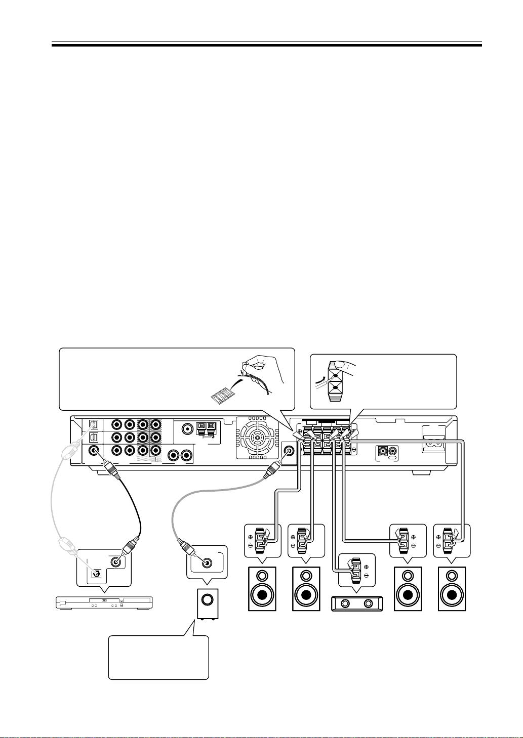
1) Hook up your DVD player, speakers, subwoofer and TV.
Connect your DVD player to this unit using either the coaxial digital terminal or the optical digital terminals,
depending on which type of digital terminal your DVD has. The quality of these two types of connection is the same
so it’s simply a matter of matching like with like, and you don’t need to do both. It is easiest, however, if you follow
this receiver’s default settings and connect your DVD player to coaxial terminal. If your DVD player does not have an
coaxial terminal, use one of the optical terminal to hook it up to this receiver. (In this case you need to assign the
DVD function to that terminal. See p.31 in order to do this.) Follow the diagram below to hook up your DVD player
to either the coaxial or optical terminal(s). Then, hook up the speakers you want to use with this receiver. This
receiver can be used with just two speakers but it’s better to have five speakers to get accurate surround sound. See
pages 16-17 for more details on connecting your speakers. Next, hook up your powered subwoofer, if you have one.
For all speakers make sure to connect the positive (+) and negative (–) terminals on the receiver and speakers with
the same wire (positive to positive, negative to negative).
Before hooking up your speakers affix
the color-coded sticker with the
appropriate name (for example,
“FRONT R”) to the speaker wire so
you always know which speaker that
wire is connected to.
TV/
TV/
SAT
(DVD)
OPT1
DVR /
VCR
OPT2
DVD
(TV/
SAT)
COAX
Optical cable
(sold sepa-
SAT
IN
DVR /
VCR
IN
DVD
IN
R
L
AUD IODIGITAL IN AUD IOVIDEO
Coaxial cable
(sold separately)
1
MONITOR
OUT
2
DVR /
VCR
OUT
R
rately, don’t
pinch or bend
cable sharply)
DIGITAL AUDIO OUT
COAXIAL
OPTICAL
OPEN/
CLOSE
0
Î
3
¡
1
8
¢
7
STANDBY/ON
4
DVD Player
(DV-454, etc.)
When you’re hooking up
your subwoofer make
sure its power cord is
disconnected.
FM UNBA L75
Ω
LOOP
AM
ANTENNA
L
Audio cord
(sold separately)
LINE LEVEL
Front R
(R)
Powered
Subwoofer (SW)
While pressing down
the speaker tab push the
speaker wire into the
terminal and release
speaker terminal tab.
SPEAKERS
FRONT SURROUND
SUB
WOOFER
OUT
CENTER LRLR
IN
OUT
CONTROL
AC IN
Speaker wire
(sold separately)
Front
(L)
Center
L
(C)
Surround R
(RS)
Surround L
If you only hook up two speakers set the Listening
mode to one of the modes for two channel outputs.
(LS)
6
En
Page 7
English
Video cord
(sold separately)
Quick Start Guide
TV/
SAT
(DVD)
OPT1
DVR /
VCR
OPT2
DVD
(TV/
SAT)
COAX
Video cord
(sold separately)
S
1
STANDBY/ON
4
TV/
SAT
IN
DVR /
VCR
IN
DVD
IN
R
L
AUD IODIGITAL IN AUD IOVIDEO
VIDEO OUT
¡
¢
7
1
MONITOR
OUT
FM UNBA L75
2
DVR /
VCR
OUT
OPEN/
CLOSE
0
Î
3
8
Ω
LOOP
AM
ANTENNA
R
L
DVD Player
(DV-454, etc.)
MONITOR IN
WOOFER
SUB
OUT
SPEAKERS
FRONT SURROUND
CENTER LRLR
TV
CONTROL
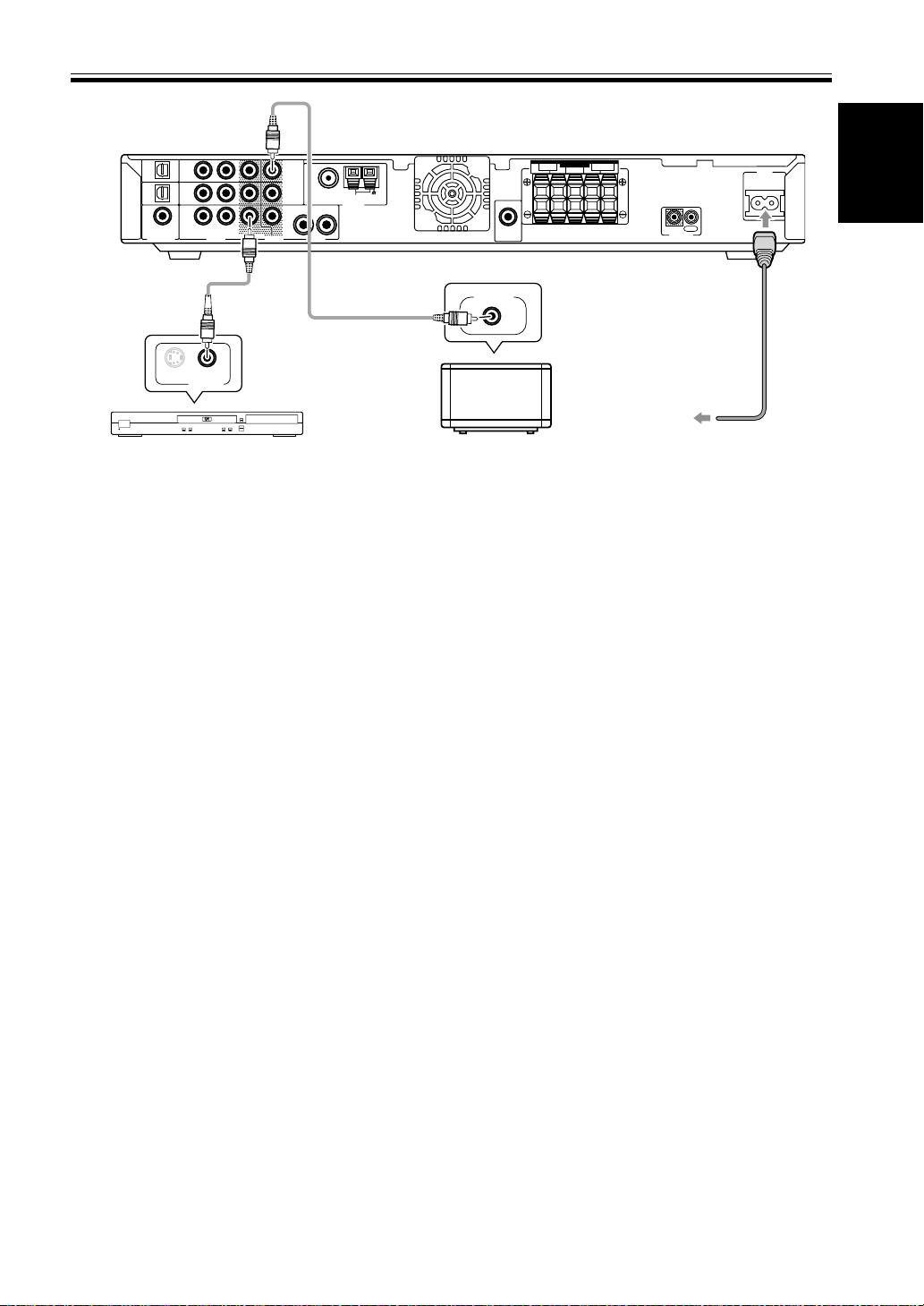
To wall
outlet
IN
OUT
AC IN
Power cord
Lastly, hook up your DVD player to the DVD IN VIDEO and your TV to the MONITOR OUT VIDEO terminals as
shown above and plug in the receiver’s power cord to a power outlet.
Automatic speaker setup (receiver automatically configures Front, Center, Surround speakers and Subwoofer)
Once you have completed the above tasks, the receiver will automatically detect which speakers you have connected
and configure your speaker settings according to that. You don’t have to do anything. This setup establishes the size
and configuration of the speaker system you have connected and is the easy way to setup your speakers for surround
sound. If you don’t have surround speakers or want to make more exact speaker settings, go to page 27.
The Automatic speaker setup will give you acceptable surround sound.
2) Turn on the power on the receiver, your DVD player, your powered
subwoofer and TV.
• Make sure your TV is set to the receiver. If it is not, check the input jack this receiver is hooked up to on your TV
and consult the manual that came with the TV to figure out the proper TV setting.
• Confirm that DVD appears in the receiver’s display, indicating that the receiver is set to the DVD input. If it does
not, press the DVD button to set the receiver to DVD input.
3) Confirm the settings on your DVD player are correct for the source you
want to play.
Make sure your DVD player is outputting a digital signal and choose the soundtrack (Dolby Digital, DTS, etc.) that
you want to hear. If you are unsure about your DVD player’s settings, see page 24 for more information and/or
consult the manual that came with your DVD player.
4) Play a source (like a DVD) and adjust the volume to your liking.
You are now ready to experience home theater with your new surround sound system.
7
En
Page 8

Quick Start Guide
Advanced/Customized Settings
If you want to customize your home theater to your environment, equipment or personal tastes, many settings are
available. One of the most important advanced settings, called Room Setup, establishes the distances between your
speakers and your normal listening position (as well as volume levels, etc.). Making this setting should improve your
surround sound. Room Setup is explained on page 26. After that you could go on to fine tune your surround sound
for maximum sound quality. These settings start on page 27.
The VSX-C100 has many different listening modes to accommodate many different kinds of sources, speaker
configurations and sound reproduction. Experiment with these features to figure out what suits your tastes.
The listening mode explanations and settings start on page 33.
The above is a quick guide to getting you started with your home theater system and a few setup suggestions. It is a
good idea, however, to read this manual in its entirety so you understand what you can do with the VSX-C100 and
the possibilities of home theater in general. You may find many hints in these explanations that help you get better
sound and let you operate all your equipment more effectively.
8
En
Page 9
English
Introductory Information
01
Checking the Supplied
Accessories
Please check that you've received the following supplied
accessories:
• AM loop antenna
• FM wire antenna
• Power cord
• Dry cell batteries (AA Size / IEC R6P) x2
• Remote control unit
• Operating instructions
• Speaker cord labels
Installing the Receiver
• When installing this unit, make sure to put it on a
secure and level plane that is stable.
• Don’t place it on the following places:
– on a color TV (the screen may distort)
– near a cassette deck (or close to a device that gives off a
magnetic field) This may interfere with the sound.
– in direct sunlight
– in damp or wet areas
– in extremely hot or cold areas
– in places where there is a vibration or other movement
– in places that are very dusty
– in places that have hot fumes or oils (such as a kitchen)
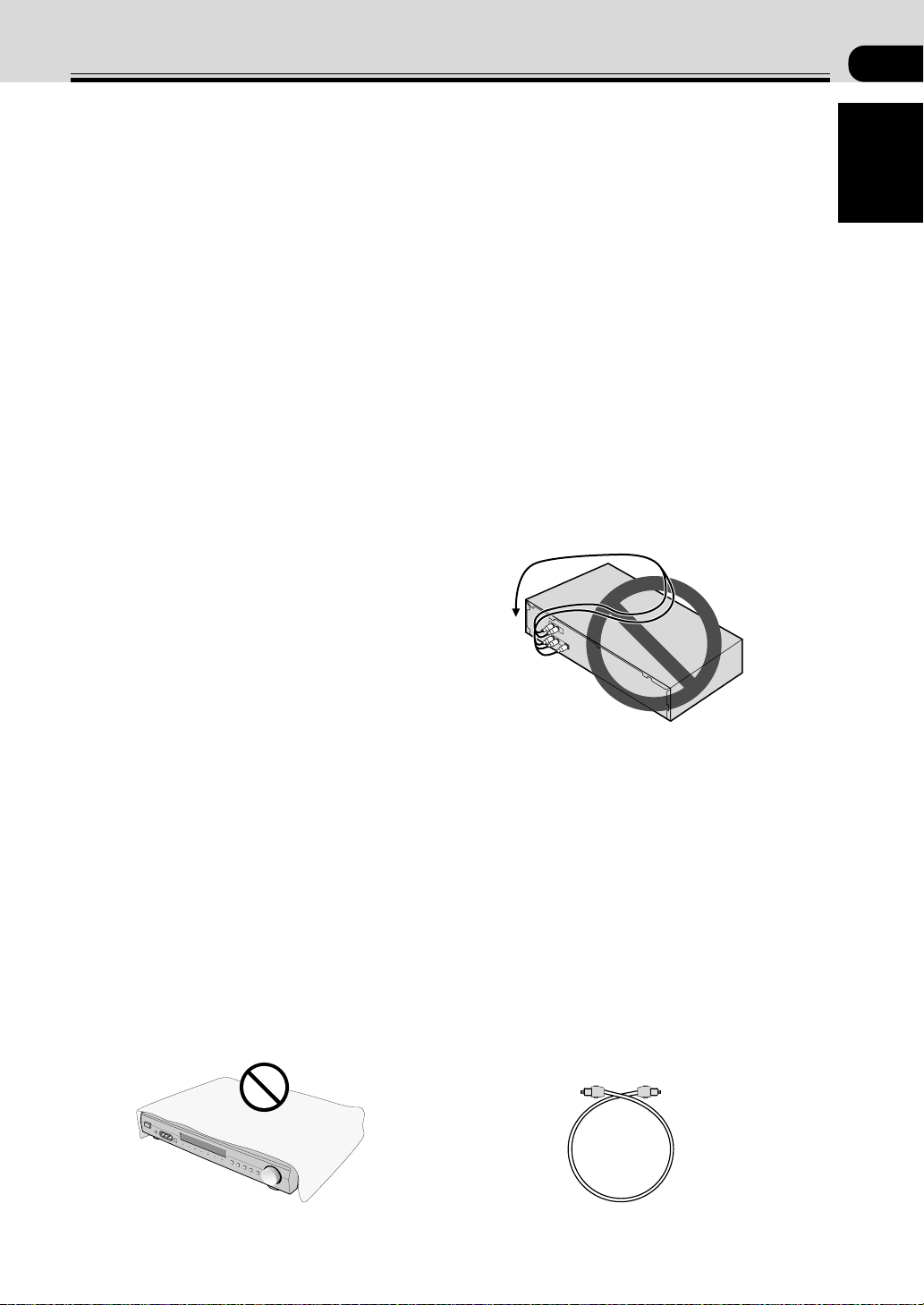
• Don’t place anything on top of the receiver except for
a Pioneer DV-454, 350, 444 or 545 DVD player. If
you do place one of these pieces of equipment on top
of the receiver be sure to leave the ventilation space
over it as prescribed above.
• The receiver may become hot while in use, please
take care around it.
When Making Cable
Connections
Be careful not to arrange cables in a manner that bends
the cables over the top of this unit. If the cables are laid
on top of the unit, the magnetic field produced by the
transformers in this unit may cause a humming noise to
come from the speakers.
Ventilation
• When installing this unit, make sure to leave space
around the unit for ventilation to improve heat
dispersal (at least 20 cm at the top, 50 cm at the rear,
and 10 cm at each side). If not enough space is
provided between the unit and walls or other
equipment, heat will build up inside, interfering with
performance and/or causing malfunctions. See below
for exceptions to this.
• If using a rack to hold the receiver make sure the
back of the rack and the left side are open.
• Also, if you’re using a case with glass doors, leave the
glass doors open when using the receiver.
• Do not place on a thick carpet, bed, sofa or fabric
having a thick pile. Do not cover the receiver with
fabric or other covering. Anything that blocks
ventilation will cause the internal temperature to rise,
which may lead to breakdown or fire hazard.
Cassette deck placement
Depending on where the cassette deck is placed, noise
may occur during playback of your cassette deck which
is caused by leakage flux from the transformer in the
receiver. If you experience noise, move the cassette deck
farther away from the receiver.
Storing optical cable
When storing optical cable, coil loosely as shown below.
The cable may be damaged if bent around sharp corners.
more
+ than =
(15 cm)
En
9
Page 10
Introductory Information
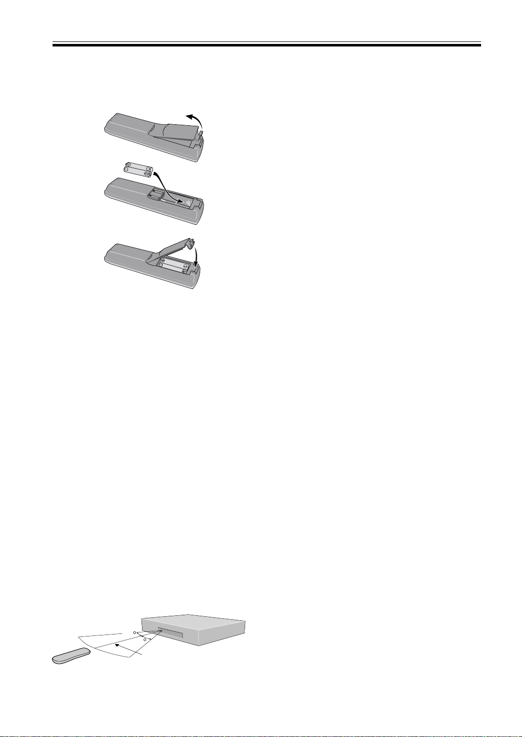
Loading the Batteries
The remote control operates on two AA batteries
(supplied).
1
2
3
CAUTION:
Incorrect use of batteries may result in such hazards as
leakage and bursting. Observe the following precautions:
• Never use new and old batteries together.
• Insert the plus and minus sides of the batteries
properly according to the marks in the battery case.
• Batteries of the same shape may have different
voltages. Do not use different batteries together.
• When disposing of used batteries, please comply
with governmental regulations or environmental
public institution’s rules that apply in your country or
area.
Maintenance of External
Surfaces
• Use a polishing cloth or dry cloth to wipe off dust
and dirt.
• When the surfaces are dirty, wipe with a soft cloth
dipped in some neutral cleanser diluted five or six
times with water, and wrung out well, and then wipe
again with a dry cloth. Do not use furniture wax or
cleansers.
• Never use thinners, benzine, insecticide sprays or
other chemicals on or near this unit, since these will
corrode the surfaces.
10
En
Operating Range of the
Remote Control Unit
The remote control may not work properly if:
• There are obstacles between the remote control and
the receiver's remote sensor.
• Direct sunlight or fluorescent light is shining onto the
remote sensor.
• The receiver is located near a device that is emitting
infrared rays.
• The receiver is operated simultaneously with another
infrared remote control unit.
30
30
7m
Page 11
English
Connecting Y our Equipment
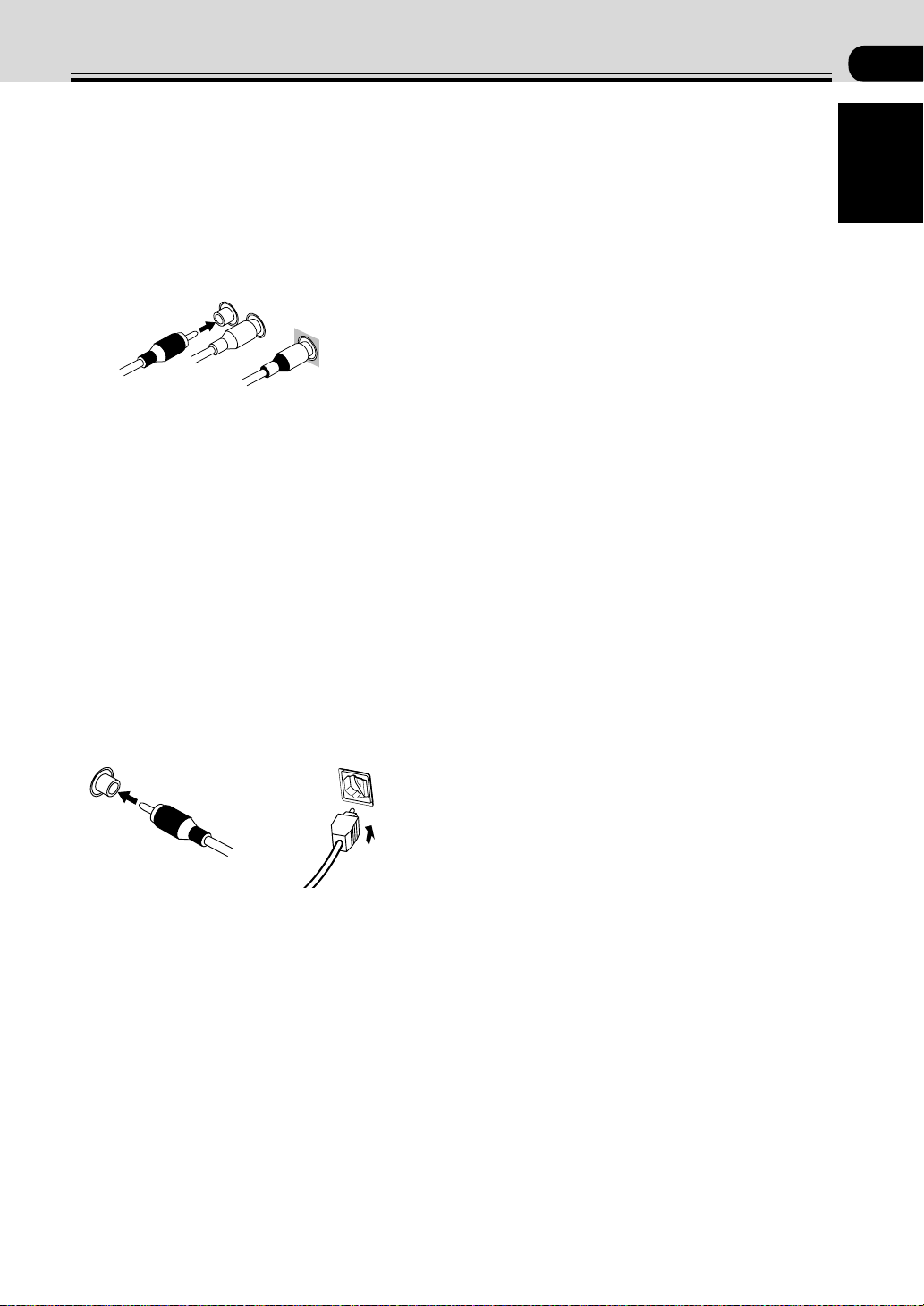
Audio/Video Cords
Use audio/video cords (not supplied) to make analog
audio and video connections.
Connect red plugs to R (right), white plugs to L (left),
and the yellow plugs to VIDEO.
Be sure to insert completely.
R
L
VIDEO
Coaxial Cords/Optical Cables
Commercially available digital audio coaxial cords
(standard video cords can also be used) or optical cables
(not supplied) are used to connect digital components to
this receiver.
Be sure to insert completely and in the case of the
optical cable, right-side up. If it is inserted improperly it
can break the shutter on the optical terminal (this won't,
however, affect the connection or insertion of an optical
cable).
02
Coaxial cord
(or standard composite
video cord)
Optical cable
11
En
Page 12
Connecting Y our Equipment
Before making or changing the connections, switch off the power and disconnect the power cord from the AC wall
outlet.
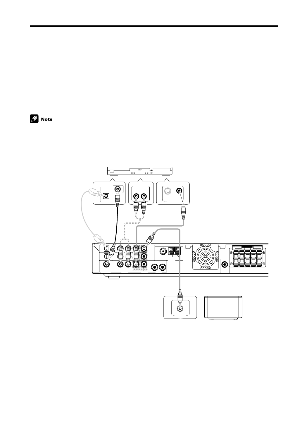
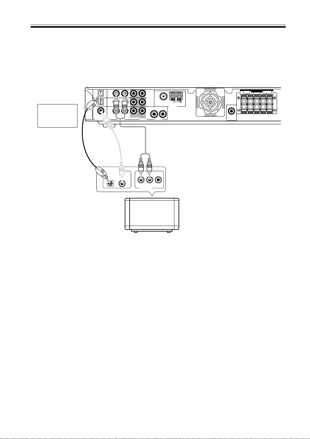
Connecting a DVD Player & TV
In order to play PCM/
22
2 Digital/DTS multichannel soundtracks, you need to make digital audio connections.
22
Connect your DVD player to this unit using either the coaxial digital terminal or the optical digital terminals,
depending on which type of terminal your DVD has. The quality of these two types of connection is the same so it’s
simply a matter of matching like with like. It is easiest, however, if you follow this receiver’s default settings and
connect your DVD player to coaxial terminal. If your DVD player does not have an coaxial terminal, use the optical
terminal to hook it up to this receiver. In this case you need to assign the DVD function to that terminal. See p.31 in
order to do this. Follow the diagram below to hook up your DVD player to either the coaxial or optical terminal(s).
Also, connect your TV to this receiver as shown below.
The basic default settings for the DIGITAL IN terminals are as follows: COAX: DVD; OPT. 1: TV/SAT; OPT. 2: DVR. If
you need to use an optical terminal for your DVD use OPT.1. In this case, assign your coaxial terminal to TV/SAT (see
p.31) and the optical default settings change to: OPT. 1: DVD; OPT. 2: DVR.
Optical cable
(sold separately,
don’t pinch or
DIGITAL AUDIO OUT
COAXIAL
OPTICAL
Coaxial
cable (sold
separately)
DVD Player (DV-454, etc.)
1
STANDBY/ON
4
¡
¢
7
ANALOG OUT
LR
OPEN/
CLOSE
0
Î
3
8
S
VIDEO OUT
Video cord
(sold separately)
bend cable
sharply)
TV/
TV/
SAT
SAT
(DVD)
IN
OPT1
DVR /
DVR /
VCR
VCR
IN
OPT2
DVD
(TV/
DVD
SAT)
IN
COAX
R
L
AUD IODIGITAL IN AUD IOVIDEO
1
MONITOR
OUT
2
DVR /
VCR
OUT
FM UNBA L75
Ω
LOOP
AM
ANTENNA
R
L
SUB
WOOFER
OUT
SPEAKERS
FRONT SURROUND
CENTER LRLR
12
En
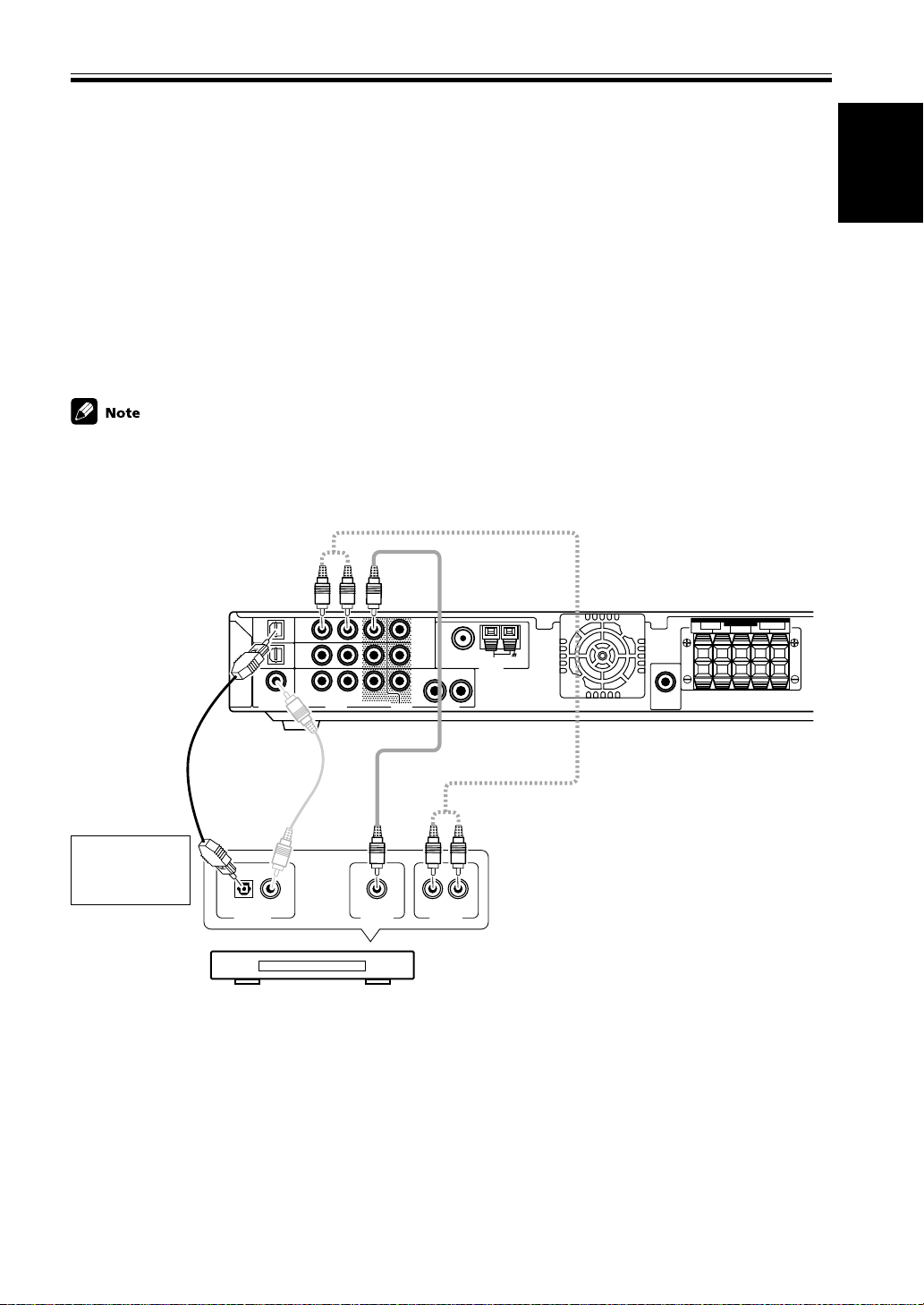
Why you need an analog connection as well as a
digital one:
• If you don’t have an digital output on your DVD
player you will need to use the analog connection
shown here.
• If you want to get an audio signal from the VCR
out you need an analog connection.
• If you want to use your DVD player for karaoke
you need an analog connection.
Video cord (sold separately)
MONITOR IN
TV
Page 13
English
Connecting Y our Equipment
Before making or changing the connections, switch off the power and disconnect the power cord from the AC wall
outlet.
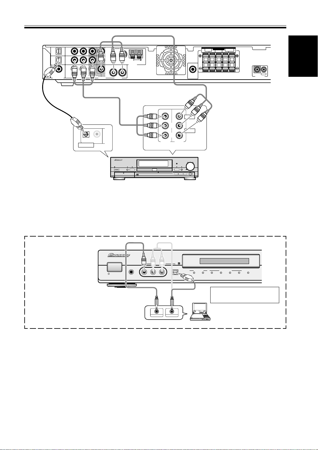
Connecting a Digital Tuner/Set Top Box
If you have an external digital tuner (like a set top box for satellite or cable TV) you need to connect it to either the
optical digital terminals or the coaxial digital terminal in order to play digital cable/satellite broadcasting. The quality
of these two types of connection is the same so it’s simply a matter of matching like with like. It is easiest, however, if
you follow this receiver’s default settings and connect your cable/satellite tuner (or TV/SAT as it’s called on the remote
control) to optical terminal 1. If your TV/SAT does not have an optical terminal, use the coaxial terminal to hook it up
(consult the DVD hook up information on the previous page). In this case you need to assign the TV/SAT function to
that terminal. See p.31 in order to do this. Follow the diagram below to hook up your TV/SAT to either the optical or
coaxial terminal.
Make sure you use a digital connection as well as an analog one for the audio on the cable/satellite tuner, as pictured
below.
The basic default settings for the DIGITAL IN terminals are as follows: COAX: DVD; OPT. 1: TV/SAT; OPT. 2: DVR. If
you need to use the coaxial terminal for your TV/SAT, then assign the coaxial terminal to TV/SAT. The digital terminals settings change to: COAX: TV/SAT; OPT. 1: DVD; OPT. 2: DVR. (see p.31)
Optical cable (sold
separately, don’t
pinch or bend
cable sharply)
Match the shape
of terminal and
the optical plug.
TV/
SAT
(DVD)
OPT1
DVR /
VCR
OPT2
DVD
(TV/
SAT)
COAX
Coaxial cable
(sold separately)
DIGITAL OUT
Digital Set Top Box
TV/
SAT
IN
DVR /
VCR
IN
DVD
IN
R
L
AUD IODIGITAL IN AUD I OVIDEO
1
MONITOR
OUT
FM UNBAL75
2
DVR /
VCR
OUT
Ω
LOOP
AM
ANTENNA
R
L
Video cord (sold separately)
Audio cord
(sold separately)
LR
VIDEO OUT
AUDIO OUT
Why you need an analog connection as well as a
digital one:
• If you don’t have an digital output on your TV tuner
you will need to use an analog connection.
• If the program you want to watch isn’t output from
the digital terminals you need an analog connection.
• If you want to get a signal from a video deck instead
of a TV tuner you need an analog connection.
SUB
WOOFER
OUT
SPEAKERS
FRONT SURROUND
CENTER LRLR
13
En
Page 14
Connecting Y our Equipment
Before making or changing the connections, switch off the power and disconnect the power cord from the AC wall
outlet.
Connecting a TV with an Internal Digital Tuner
If you have an TV with an internal digital tuner follow the directions above for an external digital tuner and in
addition hook up your TV, if you have not already done so when you hooked up your DVD player (see the previous
page). Make sure you use a digital connection as well as an analog one for the audio, as pictured below.
TV/
TV/
SAT
SAT
(DVD)
IN
OPT1
DVR /
DVR /
VCR
VCR
IN
OPT2
Match the shape
of terminal and
the optical plug.
Optical cable (sold
separately, don’t
pinch or bend cable
sharply)
DVD
(TV/
DVD
SAT)
IN
COAX
Coaxial
cable (sold
separately)
DIGITAL OUT
R
L
AUD IODIGITAL IN AUD IOVIDEO
ANALOG OUT
Connecting Video Components
1
MONITOR
OUT
FM UNBAL75
2
DVR /
VCR
OUT
Ω
LOOP
AM
ANTENNA
R
L
Audio cord
(sold separately)
WOOFER
TV with an
internal digital tuner
SUB
OUT
SPEAKERS
FRONT SURROUND
CENTER LRLR
14
En
Connect your video components to the terminals as shown below.
If you have a Digital Video Recorder (a DVR) you need to connect it digitally to either the optical digital terminals or
the coaxial digital terminal in order to play and/or record multichannel sound. The quality of these two types of
connection is the same so it’s simply a matter of matching like with like and using the available terminal(s) after
you’ve hooked up your DVD player and cable/satellite/TV tuner.
Basically the easiest way to connect a DVR is to follow this receiver’s default settings and connect your cable/satellite
tuner (or TV/SAT as it’s called on the remote control) and DVR to optical terminals 1 and 2 respectively, and connect
the DVD to the coaxial terminal.
If this isn’t possible due to the types of terminals each component is equipped with, then you need to figure out
which component will be used for the coaxial terminal and assign it properly (see p. 31). After that follow the optical
terminal defaults (as below).
If you connected the coaxial terminal to DVD and thus left it on the default DVD setting the optical terminals default
settings are:
OPT. 1: TV/SAT
OPT. 2: DVR
If you assigned the coaxial terminal to TV/SAT the optical terminals default settings are:
OPT. 1: DVD
OPT. 2: DVR
All video decks (both DVRs and VCRs) should be hooked up with analog connections as well. If you want to record
programs it is necessary to connect to the DVR/VCR IN AUDIO terminals as shown next page.
Page 15
English
Connecting Y our Equipment
TV/
SAT
(DVD)
OPT1
DVR /
VCR
OPT2
DVD
(TV/
SAT)
TV/
SAT
IN
DVR /
VCR
IN
DVD
IN
COAX
R
L
AUD IODIGITAL IN AUD IOVIDEO
1
MONITOR
OUT
2
DVR /
VCR
OUT
FM UNBAL75
Ω
LOOP
AM
ANTENNA
R
L
SUB
WOOFER
OUT
SPEAKERS
FRONT SURROUND
CENTER LRLR
IN
CONTROL
OUT
Audio/video cord
(sold separately)
Audio/video cord
(sold separately)
VIDEO
OUTPUT
L
R
/AUTO REC
Î
INPUT 2
DVD
TIMER
AUTO REC
OPEN/CLOSE
0
38
STOP PLAY
7
FUNCTION
PAUSE
AUDIO
DVD RECORDER
SMART JOG
DVR-7000
REC
Optical cable (sold
separately, don’t
pinch or bend
cable sharply)
OPTICAL COAXIAL
DIGITAL OUT
DIGITALFL OFF
2
STANDBY/ON
FL DIMMER
DISCNAVI
OPEN
DVD Recorder (DVR-7000, etc.)
You can only record audio signals from video components hooked up with analog connections.
If the input component and the receiver are only connected with an digital cable (coaxial or optical), which is for
audio, you need to connect analog video and audio cables in order to be able to record video programs with
soundtracks.
Front
Select the component hooked
up to the Front video
connections with the FRONT
button on the remote control
or front panel.
STANDBY/ON
PHONES
FRONT INPUT
VIDEO AUDIO
L
VIDEO IN/OUT
R
DIGITAL IN
AUDIO IN/OUT
DIGITAL
2
INPUT SIGNAL
DIGITAL OUT (OPTICAL)
SURROUND MODE
PHONES
/VIRTUAL
2
PRO LOGIC II
ADVANCED
DTS
AUTO
Match the shape of terminal
and the optical plug.
COLOR BRIGHT MONITOR
Portable DVD Player (etc.)
PHONES
HOLDON/OFF
SOUND
MODE
15
En
Page 16
Connecting Y our Equipment
ª
·
Before making or changing the connections, switch off the power and disconnect the power cord from the AC wall
outlet.
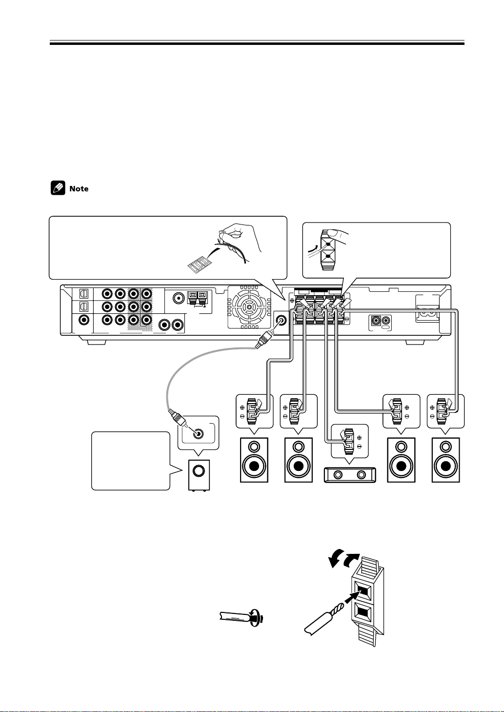
Connecting Speakers
A full complement of five speakers is shown here but, naturally, everyone’s home setup will vary. Simply connect the
speakers you have in the manner described below. The receiver will sense which speakers you have hooked up. The
receiver will work with just two stereo speakers (called “Front” speakers in the diagram) but we recommend you use
five speakers. If you don’t hook up surround speakers you need to adjust the Listening mode settings (see p. 33).
Make sure you connect the speaker on the right to the right terminal and the speaker on the left to the left terminal.
Also make sure the positive and negative (+/–) terminals on the receiver match those on the speakers.
• Use speakers with a nominal impedance of 6 Ω to 16 Ω.
Before hooking up your speakers
affix the color-coded stickers with
the appropriate names (for example,
“FRONT R”) to the speaker wire so
you always know which speaker
each wire is connected to.
TV/
TV/
SAT
SAT
(DVD)
IN
OPT1
DVR /
DVR /
VCR
VCR
IN
OPT2
DVD
(TV/
DVD
SAT)
IN
COAX
R
L
AUD IODIGITAL IN AUD IOVIDEO
1
MONITOR
OUT
2
DVR /
VCR
OUT
FM UNBA L75
R
L
Audio cord
(sold separately)
When you’re
hooking up your
subwoofer make
sure its power cord
is disconnected.
Powered
Subwoofer (SW)
Ω
LOOP
AM
ANTENNA
LINE LEVEL
Front R
(R)
SUB
WOOFER
OUT
Front L
SPEAKERS
FRONT SURROUND
CENTER LRLR
(L)
While pressing down the
speaker tab push the
speaker wire into the
terminal and release
speaker terminal tab.
IN
OUT
CONTROL
Speaker wire
(sold separately)
Center
(C)
Surround R
(RS)
AC IN
Surround L
(LS)
16
En
Speaker terminals
Use good quality speaker wire to connect the speakers to the receiver.
1 Twist about 10 mm of bare wire strands together.
2 Push in the speaker terminal tab and insert the wire.
3 Release speaker terminal tab, it should snugly grip the speaker wire.
10 mm
Caution:
Make sure that all the bare speaker wire is twisted together and inserted fully into the speaker terminal. If any of the
bare speaker wire touches the back panel it may cause the power to cut off as a safety measure.
Page 17
English
Connecting Y our Equipment
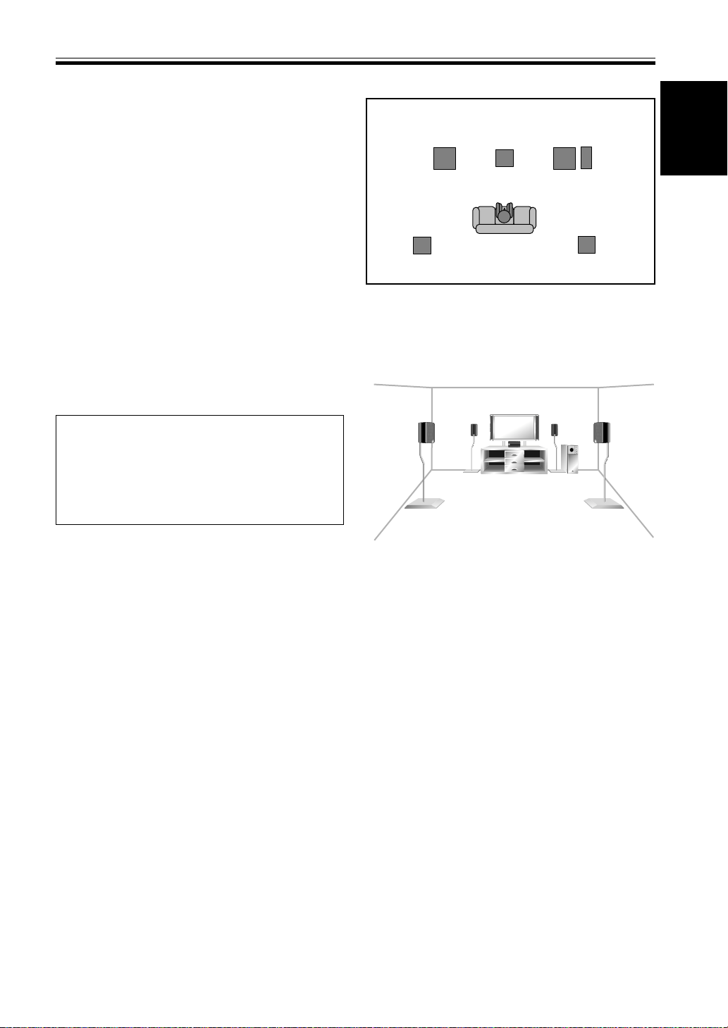
Hints on Speaker Placement
Speakers are usually designed with a particular placement in mind. Some are designed to be floor standing,
while others should be placed on stands to sound their
best. Some should be placed near a wall; others should
be placed away from walls. Follow the guidelines on
placement that the speaker manufacturer provided with
your particular speakers to get the most out of them.
• Place the front left and right speakers at equal
distances from the TV.
• When placing speakers near the TV, we recommend
using magnetically shielded speakers to prevent
possible interference, such as discoloration of the
picture when the TV is switched on. If you do not
have magnetically shielded speakers and notice
discoloration of the TV picture, move the speakers
farther away from the TV.
• Install the center speaker above or below the TV so
that the sound of the center channel is localized at
the TV screen.
CAUTION!
If you choose to install the center speaker on top
of the TV, be sure to secure it by suitable means to
reduce the risk of damage or injury resulting from
the speaker falling from the TV in the event of
external shocks such as earthquakes.
Overhead view of speaker set up
Front Left (L)
Surround
Left (LS)
Center (C)
Listening Position
3-D view of speaker set up
Front
Right (R)
Subwoofer
(SW)
Surround
Right (RS)
• If possible, install the surround speakers slightly
above ear level.
• Try not to install the surround speakers farther away
from the listening position than the front and center
speakers. Doing so can weaken the surround sound
effect.
• Install the subwoofer on the same plane as the front
speakers.
To achieve the best possible surround sound, install your
speakers as shown on the right. Be sure all speakers are
installed securely to prevent accidents and improve
sound quality.
17
En
Page 18
Connecting Y our Equipment
Before making or changing the connections, switch off the power and disconnect the power cord from the AC wall
outlet.
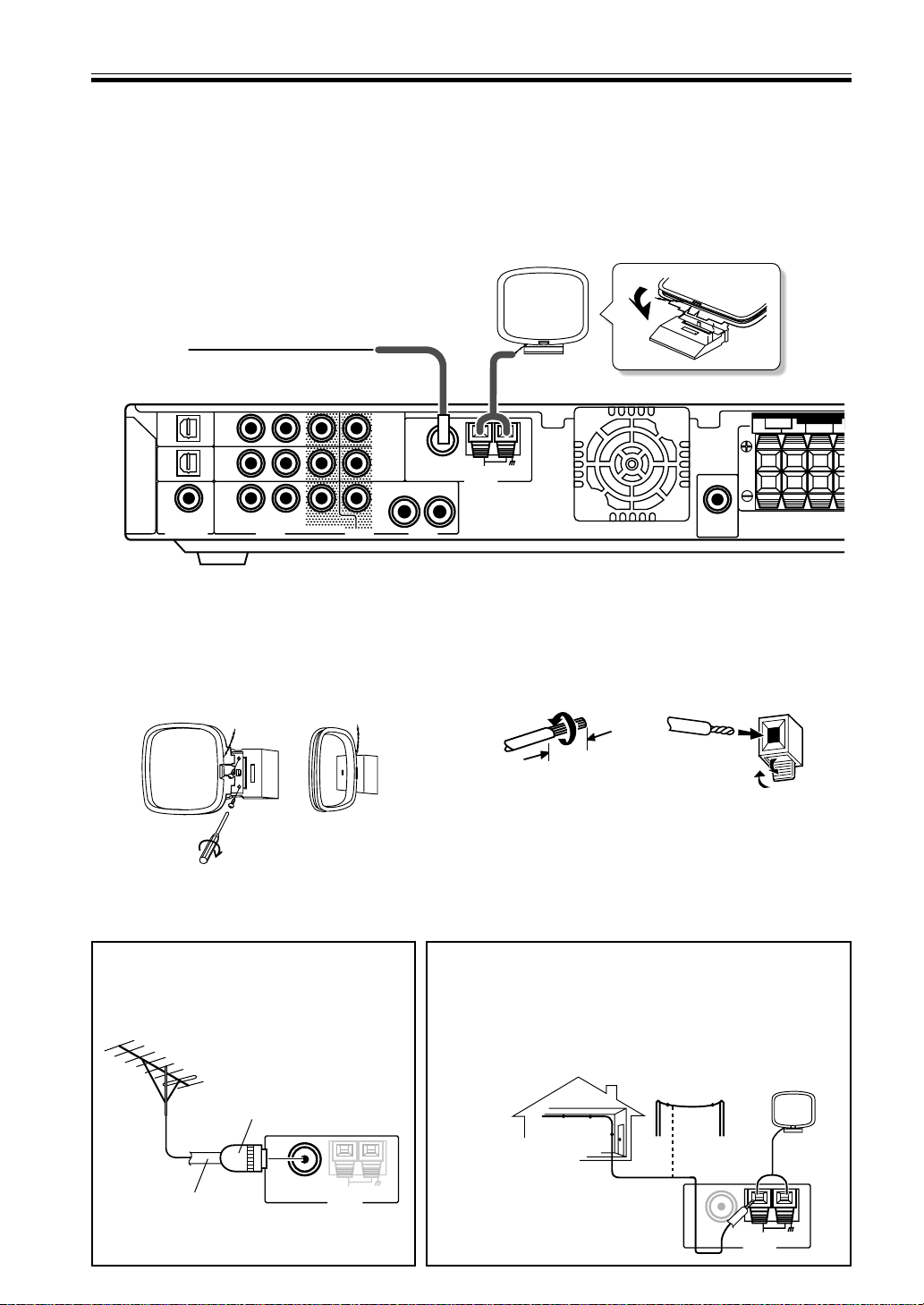
Connecting Antennas
Connect the AM loop antenna and the FM wire antenna as shown below. To improve reception and sound quality,
connect external antennas (see Using External Antennas, below).
TV/
SAT
(DVD)
OPT1
DVR /
VCR
OPT2
DVD
(TV/
SAT)
COAX
TV/
SAT
IN
DVR /
VCR
IN
DVD
IN
R
L
AUD IODIGITAL IN AUD IOVIDEO
1
MONITOR
OUT
2
DVR /
VCR
OUT
AM loop antenna
Assemble the antenna and connect to the receiver.
Attach to a wall, etc. (if desired) and face in the
direction that gives the best reception.
Using External Antennas
R
FM UNBAL75
L
FRONT
Ω
LOOP
AM
ANTENNA
SUB
WOOFER
OUT
AM Antenna connectors
Twist the exposed wire strands together push the tab
back, insert into the hole and release connector.
10mm
FM wire antenna
Connect the FM wire antenna and fully extend vertically
along a window frame or other suitable area.
SPEAKERS
CENTER RLR
18
En
To improve FM reception
Connect an external FM antenna.
PAL connector
FM UNBAL75
Ω
AM
75 Ω coaxial cable
ANTENNA
LOOP
To improve AM reception
Connect a 5-6 m length of vinyl-coated wire to the AM
antenna terminal without disconnecting the supplied AM loop
antenna.
For the best possible reception, suspend horizontally outdoors.
Outdoor antenna
Indoor antenna
(Vinyl-coated wire)
5–6m
FM UNBAL75
Ω
LOOP
AM
ANTENNA
Page 19

English
Connecting Y our Equipment
R
Operating other Pioneer Components with this Unit’s Sensor
By connecting a control cord to the CONTROL terminals of the respective equipment, you can control several Pioneer
components using one remote sensor. Following the diagram below you will see that one component feeds the
CONTROL OUT terminal and on the other end another component is connected to the CONTROL IN terminal. The
component that is the end point (the one that has a cord hooked up to its CONTROL OUT only) it is the component
whose sensor you will use. Point the remote control at that sensor when you want to operate the any of the equipment connected by this system. In the example below you would point the remote control unit towards the remote
sensor of the equipment on the left.
• You can also control Pioneer components by pointing the receiver's remote control directly at the component.
This type of operation does not require control cords. See page 47 for more information.
• To use this kind of remote control you have to hook up a control cord AND the have the component and receiver
hooked up with analog RCA audio/video cords as well (see pages 12–15).
Point remote control towards
remote sensor of component
that only has a cord connected
Components with
an CONTROL
terminals
Components with
an CONTROL
terminals
to its CONTROL OUT
terminal
Mono mini plug
(optional)
TV/
TV/
SAT
SAT
(DVD)
IN
OPT1
DVR /
DVR /
VCR
VCR
IN
OPT2
DVD
(TV/
DVD
SAT)
IN
COAX
R
L
AUD IODIGITAL IN AUD IOVIDEO
1
MONITOR
2
DVR /
VCR
OUT
OUT
FM UNBAL75
Ω
LOOP
AM
ANTENNA
R
L
SUB
WOOFER
OUT
SPEAKERS
FRONT SURROUND
CENTER LRLR
Mono mini plug
(optional)
IN
OUT
CONTROL
Plugging in the Receiver
After you have connected all your components, including the speakers, plug the receiver into a wall outlet.
SPEAKERS
FRONT SURROUND
CENTER LRL
IN
OUT
CONTROL
to wall outlet
• The power cord is removable from main unit for storage.
AC IN
Power cord CAUTION!
Handle the power cord by the plug. Do not pull
out the plug by tugging the cord and never
touch the power cord when your hands are wet
as this could cause a short circuit or electric
shock. Do not place the unit or a piece of furniture, etc., on the power cord, or pinch the cord.
Never make a knot in the cord or tie it with
other cords. The power cords should be routed
such that they are not likely to be stepped on.
A damaged power cord can cause a fire or give
you an electrical shock. Check the power cord
once in a while. When you find it damaged,
ask your nearest PIONEER authorized service
center or your dealer for a replacement.
AC IN
19
En
Page 20

03
Displays & Controls
Front Panel
0 - = ~!
9
PHONES
STANDBY/ON
FRONT INPUT
VIDEO AUDIO
L
DIGITAL IN
R
DIGITAL
2
INPUT SIGNAL
#@$
AUDIO/VIDEO MULTI-CHANNEL RECEI V E R VSX-C100
MASTER
VOLUME
DVD FM/AM FRONT
SURROUND MODE
2
DTS
AUTO
PHONES
PRO LOGIC II
/VIRTUAL
ADVANCED
SOUND
MODE
DVR/VCRTV/SAT
R
DOWN UP
20
En
1
2
3
1 STANDBY/ON (Main power) button
Pressing this button switches the receiver ON from
STANDBY mode.
RECEIVER
button on the remote control also
toggles between ON and STANDBY mode.
The receiver uses a small amount of electricity (less
than 1W) in STANDBY mode.
2 PHONES jack
Use to connect headphones (this switches the
speakers off).
3 FRONT INPUT
You can connect a portable DVD player, video
camera, video game system, or whatever equipment
you would like to have handy, to the FRONT INPUT
(refer to page 15).
4 INPUT SIGNAL indicators
Indicates the kind of input signal.
2 DIGITAL:
When a 2 DIGITAL source is input this indicator
will light.
DTS:
When a DTS source is input this indicator will light.
5 SURROUND MODE indicators
Indicates the SURROUND mode of input signal.
AUTO:
Lights when the AUTO mode is selected. This mode
automatically selects which kind of signal is being
input and plays back in the appropriate mode.
PHONES/VIRTUAL:
Lights when the VIRTUAL or PHONES SURROUND
mode is selected. The VIRTUAL mode simulates
surround sound for two speakers (when headphones
are not plugged in, see p.33). The PHONES SURROUND mode simulates surround sound for
headphones, when they are plugged in.
2 PRO LOGIC II:
Lights when the 2 PRO LOGIC II mode is selected.
This mode automatically plays back in 2 PRO
LOGIC II (see p.33).
4
65
7
8
ADVANCED:
Lights when an ADVANCED mode is selected. These
modes playback emphasizing certain characteristics
of the sound (see p.33–34).
6 SOUND MODE
Lights when you have chosen one of the sound
modes to be applied to playback (see p.35).
7 Input buttons
Use to select the playback source: the possibilities are
DVD, TV/SAT, DVR/VCR, FM/AM and FRONT.
8 MASTER VOLUME
Use to set the overall listening volume.
DISPLAY
9 TUNER indicators
STEREO: Lights when a stereo FM broadcast is being
received in auto stereo mode.
TUNED: Lights when a broadcast is being received.
MONO: Lights when the mono mode is set using
MPX (on the remote control).
RDS: Lights when an RDS broadcast is received.
RF ATT: Lights when the RF ATT is on (see p.36).
0 Digital (DIG) & Analog (ANA) indicators
Light according to the kind of signal, digital or
analog, received (see p.44).
- 96kHz playback indicator
Lights when a 96 kHz source is being played.
= Format indicator
Shows which speakers are currently in use based on
the listening mode chosen, the source material and
the type of decoding being used (see p.24).
~ SLEEP indicator
Lights when the SLEEP function is set or active (see
p.44).
! OVER indicator
Lights when the analog signal is too powerful,
causing possible distortion (see p.31).
Page 21

English
Displays & Controls
@ EON indicators
EON lights when it has been set. The dot indicator
next to it lights when the station you are currently
tuned to carries the EON data service.
Rear Panel
# Volume level indicator
$ Character display
Shows the current input (DVD, TV/SAT, etc.),
listening mode, radio frequency, etc.
1 TV/SAT IN terminals (connect a TV/SAT set top
box here, see page 13)
Use these terminals to input a TV/SAT signal (or from
another kind of source, if you choose). Make sure to
connect to the video terminals and both the analog
and optical digital terminals for audio. To be able to
play digital surround soundtracks you need to make
digital connections. To do this it’s best to use the
optical digital terminal here but you can use the
coaxial digital terminal if necessary (in this case you
need to assign the terminal to the TV/SAT function.
See page 31 in order to do this).
2 MONITOR OUT terminals (connect a TV or
monitor here, see pages 12,14)
Use these terminals to output the signal from the
above terminals 1, 5 or 6 and FRONT INPUT.
These are video jacks. MONITOR 2 outputs the same
signal as MONITOR 1.
3 ANTENNA terminals
Connect AM or FM antennas here (see page 18).
4 SPEAKERS terminals
Use these terminals to connect speakers to the
receiver (see page 16).
5 DVR/VCR IN/OUT terminals (connect a DVR or
VCR here, see page 14–15)
Use the optical digital terminal to connect a DVR out
digitally to this receiver. There are also analog
terminals to input and output the audio and video
signal from a DVR, VCR (or a video camera, etc.).
6 DVD IN terminals (connect a DVD player here,
see page 12)
Use these terminals to input the signal from a DVD
player. Make sure to connect to the video terminals
and both the analog and coaxial digital terminals for
audio. To be able to play Dolby Digital and other
surround soundtracks you need to make digital
connections. To do this it’s best to use the coaxial
digital terminal but you can use the OPT 1 digital
terminal if necessary (in this case you need to assign
the coaxial digital terminal to the TV/SAT function.
See page 31 in order to do this).
7 SUBWOOFER OUT terminals
Use this terminal to connect a powered subwoofer to
the receiver (see page 16).
8 CONTROL IN/OUT terminal
You can use this jack to hook up other PIONEER
equipment, that bears the CONTROL terminal, so
that you can control them all with the remote control
for this receiver (see page 19).
9 AC IN (Power In)
Hook up the power cord to this terminal.
21
En
Page 22

Displays & Controls
Remote Control
All the buttons on the remote control are explained here. See pages 49 & 50 for details relating to using the remote
control with other components (like your DVD player or TV/SAT tuner).
1 RECEIVER (Power) button:
This switches between STANDBY mode and power
ON for this receiver.
2 SIGNAL SELECT button (See p.44):
Press SIGNAL SELECT repeatedly to select one of
the following:
ANALOG: To select an analog signal.
DIGITAL: To select a digital signal.
AUTO: This is the default. If there are analog and
digital signals input, the receiver automatically
selects digital. If only analog is input the
receiver will select analog.
3 Input/Control Mode Select buttons:
Use to put the receiver/remote control in the input
mode stated on the button. The FM/AM button puts
the receiver in tuner mode if it was in another mode
and switches between the FM and the AM band if
the receiver was already in tuner mode.
4 Listening Mode buttons:
AUTO button:
Use this button for direct decoding of the input
signal with no added sound effects. The receiver will
automatically detect what kind of signal (stereo,
multichannel, etc.) is being input and play accordingly.
SURROUND button (see page 34):
Use this button to choose one of the surround
listening modes this receiver is equipped with.
ADVANCED button (see page 34):
Use this button to choose one of the advanced
listening modes this receiver is equipped with.
SOUND MODE button (see page 35):
Use this button to choose one of the sound modes
this receiver is equipped with.
5 System setup buttons:
SETUP button (see page 27):
Use this button to start the receiver setup process
which adjusts the settings to your particular system.
TEST TONE button (see page 32):
Use to sound the TEST TONE when setting the
volume level of each channel.
CH SELECT button (see page 32, note):
Use to select a speaker when setting the volume
level of each channel.
ROOM SETUP button (see page 26):
Use to set the distance from your speakers to your
normal listening position.
+/– buttons (see pages 28–32):
Use these buttons when making adjustments to the
SETUP, TEST TONE, or CH.SELECT features.
1
2
3
4
5
6
7
8
9
0
RECEIVER
SIGNAL SELECT
DVD
TV/SAT
DV R/ V C R
FM/AM
AUTO
SURROUND
SETUP
TEST TONE
MUTE
MASTER
VOLUME
DISPLAY
TOP MENU MENU
EON
B
TUNE
ST
ENTER
TUNE
CLASSCMPX
INPUT
SELECT
RECEIVER
P
AUDIO
P
EXIT
SEARCH
CHANNEL CHANNEL VOLUME
FRONT
ADVANCED
CH_SELECT
T.EDIT
ST
RF ATT
D
TV CONTROL
SOURCE
SLEEP
DIMMER
SOUND
MODE
ROOM
SETUP
ENTER
MENU
SUBTITLE
GUIDE
D.ACCESS
ENTER
-
=
~
!
@
#
$
A
E
%
^
10
&
22
En
Page 23

Displays & Controls
English
ENTER button:
Use this button to enter Room Setup commands.
You can also use this button to exit a SETUP
mode.
6 Volume buttons:
MASTER VOLUME +/– buttons:
Use to set the overall listening volume.
MUTE button (see page 43):
Use to mute the sound or restore the sound if it
has been muted.
7 TOP MENU button:
Use to return to the most basic menu on a DVD
player or disc. Also used for some tuner commands.
8 AUDIO button:
Use to switch the audio tracks of a DVD when in
DVD mode or to access the EON function when
in tuner mode.
9 Number buttons:
Use to enter track number on discs or radio
frequencies.
0 CHANNEL +/– buttons:
Use to select channels on other components such
as a DVR or satellite tuner.
- LED indicator:
This indicator flashes when a command is sent
from the remote control to the receiver. It also
flashes at when teaching the receiver preset codes.
= SOURCE
Use this button to turn on and off the power of
other components.
~ SLEEP button (see page 44):
Use to put the receiver in sleep mode and select
the amount of time before the receiver turns off.
! DIMMER button (see page 43):
Press to change the display brightness. The
DIMMER button allows you to cycle through the
four different brightness strengths for the display.
@ MENU button:
Use to return to the most basic menu on a DVD
player or disc. Also used for some tuner commands.
# } ] ’ ‘ & ENTER buttons
Use these arrow buttons when adjusting the tuner
or navigating TV or DVD menus. See these
respective sections for more information.
$ SUBTITLE button:
Use to switch the subtitles on a DVD player or
disc. Also used to turn on RF ATT when in tuner
mode.
(Power) button:
% Component/Tuner/Satellite Tuner/CATV
control buttons:
The main function of these buttons (3, 7, etc.) is
to control a component (CD, for example) after
you have selected it using the Input/Control
Mode Select buttons. The tuner/satellite tuner
controls above these buttons can be accessed after
you have selected the corresponding Input/
Control Mode Select buttons (TUNER or SAT,
etc.). In this case the buttons marked with letters
(A, etc.) or EXIT will access preset channels or
functions, depending on your particular satellite/
cable TV system.
SEARCH button:
Use when searching for stations in RDS mode.
CLASS button (page 37–38):
Switches between the three banks (classes) of
radio station presets.
MPX button (page 36):
Switches between stereo and mono reception of
FM broadcasts. If the signal is weak then
switching to mono will improve the sound
quality. Also acts as a stop button for CDs, tapes,
or DVDs.
D. ACCESS button (page 37):
After pressing, you can access a radio station
directly using the number buttons.
^ ENTER button (page 49–50):
It can be used to enter commands for TV, CATV
and TUNER.
& TV CONTROL buttons:
These controls are for your TV. They are dedicated TV controls and will work no matter what
mode the remote control is in. They can,
however, be set for different TVs. By default they
will control the TV. Thus if you only have one TV,
assign it to the TV/SAT button (see page 47).
23
En
Page 24

04
Basic Playback
Checking the Settings on Your DVD (or other) Player
If you don’t set the following two features correctly you may experience problems with your surround sound (for
example: no sound whatsoever; the sound is unidimensional or lacks punch; or other problems).
1 Digital output from your DVD player or other component outputting a digital source
Set the DVD player so the signals below are output from the optical terminal (if you are unsure how to do this
check the manual that came with your DVD player). It may or may not be necessary to set the digital output on
other components, like a satellite tuner. Check the manual that came with the component.
• Dolby Digital
• DTS
• 96 kHz PCM (2 channel stereo)
2 Checking the soundtrack on your disc
Choose the surround sound signal (for example, Dolby Digital 5.1 ch or Dolby Surround) that you want to hear
from the disc. Check the manual that came with your DVD player for more information.
• Depending on your DVD player or source discs you may not be able to output sound from other than digital 2
channel stereo and analog. In this case you need to change the listening mode to SURROUND if you want
multichannel surround sound.
Program Format/Speaker Channel Indicators
One very useful feature of this receiver is the Program Format/Speaker Channel Indicators. This indicator looks
something like this:
The letters
(Input indicator)
With this indicator you can determine which channels are present in a Dolby Digital or DTS source as well as the
speakers that are currently being used. The letters L, C, R, LFE, LS & RS represent the signal being input for each
channel respectively, with LFE being the Low Frequency Effects channel which feeds your subwoofer. These letters
will only appear if the input is a Dolby Digital or DTS signal.
The triangular segments and SW represent the output from the receiver. The upper segments represent the front
left, center, and front right speakers while the bottom segments represent the surround left and surround right
channels. SW represents the subwoofer channel. If you have all of these speakers connected and are using either a
multichannel signal (for example, Dolby Digital 5.1 ch or Dolby Surround), or a listening mode to get five
channels sound, all five of the segments will light. For stereo signals only the front left, center, and front right
speakers segments will light.
In some cases, depending on the source and listening mode, the output channels may not light up.
The triangular segments and SW
(Output indicator)
24
En
Page 25

English
Basic Playback
N
U
R
Playing a Source
Here are the basic instructions for playing a disc or videotape (or any other source) with your home theater system.
The following pages will tell you about refinements you can make to the sound but the below procedure (with the
settings you have already made) should allow you to get enjoyable home theater.
1 Turn on the power of the playback compo-
nent (for example a DVD player), your TV
and subwoofer (if you have one).
2 Press RECEIVER to turn the power on.
3 Select the source (like a DVD player) you
want to playback using the individual Input
buttons on the remote control.
4 Set the signal select to AUTO (if necessary).
5 Make sure the TV is set to this receiver.
If you’re not sure which input on your TV this
receiver is hooked up to confirm the input jack on the
back of the TV and consult the manual that came
with your TV to figure out the proper setting.
6 Start playback of the component you selected
in step 3.
7 Press MASTER VOLUME (+/–) to adjust the
volume level.
2
3
RECEIVER
SIGNAL SELECT
DVD
DVR/ V C R
AUTO
SETUP
MUTE
TOP MENU MENU
P
AUDIO
EON
P
EXIT
SEARCH
E
CHANNEL CHANNEL VOLUME
TV/SAT
FM/AM
SURROUND
TEST TONE
MASTER
VOLUME
DISPLAY
ST
CLASSCMPX
INPUT
SELECT
ADVANCED
CH_SELECT
TUNE
ENTER
TUNE
TV CONTROL
FRONT
SOURCE
DIMMER
SOUND
MODE
ROOM
SETUP
ENTER
T.EDIT
ST
RF ATT
D.ACCESS
D
ENTER
SLEEP
MENU
SUBTITLE
GUIDE
A
E
10
4
7
2
STANDBY/ON button
FRONT INPUT
VIDEO AUDIO
L
STANDBY/ON
PHONES
Input buttons
SURROUND MODE
PHONES
/VIRTUAL
PRO LOGIC II
2
ADVANCED
SOUND
MODE
DVD F M/AM FRONT
RECEIVER
R
DVR/VCRTV/SAT
DIGITAL IN
INPUT SIGNAL
2
DTS
AUTO PHO
DIGITAL
MASTER VOLUME
73
AUDIO/VIDEO MULTI-CHANNEL RECEIVER
MASTER
VOLUME
R
VSX-C100
DOWN UP
• If you want to use analog sources choose analog with
the SIGNAL SELECT button (see page 44).
• When you’re using your TV’s internal tuner the TV
shouldn’t be set to this receiver (step 5 above).
• For Karaoke make sure the equipment is hooked up
SU
/VIRT
with analog connections and choose analog with the
SIGNAL SELECT button (see page 44).
25
En
Page 26

05
Fine Tuning Your Surround Sound
Room Setup
This setup establishes the distances from your speakers to your normal listening position. It is important for the
receiver to know these distances so it can output proper surround sound. Alternatively, you can make more precise
speaker distance settings on page 27-29. You don’t have to do both, however.
There are three choices for speaker distances here. They are marked ‘S’, ‘M’ and ‘L’ but they represent the relationship
between how far your front speakers and your surround speakers are from your normal listening position, i.e. the
relationship in distance between the speakers and your listening position. ‘S’ should be used when your surround
speakers are nearer your main listening position than your front speakers. ‘M’ should be used when all your speakers
are equidistant from your main listening position. ‘L’ should be used when your surround speakers are farther from
your main listening position than your front speakers.
Follow the instructions below to set the room type.
(surround speakers closer to
listening position)
LC
SIGNAL SELECT
ST
EON
E
TV/SAT
FM/AM
SURROUND
TEST TONE
MASTER
VOLUME
DISPLAY
TUNE
ENTER
TUNE
CLASSCMPX
RS
FRONT
ADVANCED
CH_SELECT
T.EDIT
ST
RF ATT
D
LS
RECEIVER
1
DVD
DVR/ V C R
AUTO
SETUP
MUTE
TOP MENU MENU
P
AUDIO
P
EXIT
SEARCH
RSW
SOURCE
SLEEP
DIMMER
SOUND
MODE
ROOM
SETUP
ENTER
MENU
SUBTITLE
GUIDE
A
D.ACCESS
E
(speakers are equidistant to
MS
listening position)
LC
LS
1 Press RECEIVER to turn the power on.
2 Press ROOM SETUP.
Cycle through the ‘S’, ‘M’, or ‘L’ settings using the ROOM
SETUP button and choose the one that best represents the
placement of your speakers around the room.
2
The setting will blink for five seconds.
3
3 While the display is blinking press ENTER.
The setting is input into the system and the display shows
ENTERED.
RSW
RS
(front speakers are closer to
L
listening position)
LC
LS
RSW
RS
26
En
STANDBY/ON button
1
PHONES
STANDBY/ON
FRONT INPUT
VIDEO AUDIO
L
• These speaker settings will automatically adjust the distance
between your listening position and the speakers as well as
the output level from each speaker. It is also possible to
INPUT SIGNAL
2
DIGITAL IN
R
DIGITAL
DTS
select these functions manually. To do so see below. For the
distance between the listening position and the speakers see
pages 27-29; For the output level of each speaker see page
32.
• The settings made most recently, whether here or manually,
on the pages mentioned directly above, will supercede any
previous settings.
• The default setting is ‘M’.
Page 27

English
Fine Tuning Your Surround Sound
Personalizing Y our Surround
Sound
This receiver will make the necessary speakers settings
automatically so you can use it to get enjoyable surround sound without doing anything, but making more
exact settings here will give you finer surround sound.
For better surround sound complete the instructions
that follow the speaker settings. Use the first two steps
on this page and continue on page 28. In this way you
can get maximum performance out of the receiver.
You only need to do these settings once (unless you
change the placement of your current speaker system or
add new speakers, etc.). The following pages offer a
more detailed description of the settings available for
each mode. The default setting is also shown on each
page.
1
2
RECEIVER
DVD
DVR/ V C R
AUTO
SETUP
MUTE
TOP MENU MENU
P
AUDIO
EON
P
EXIT
SEARCH
E
CHANNEL CHANNEL VOLUME
SIGNAL SELECT
TV/SAT
FM/AM
SURROUND
TEST TONE
MASTER
VOLUME
DISPLAY
TUNE
ST
ENTER
TUNE
CLASSCMPX
TV CONTROL
INPUT
SELECT
RECEIVER
FRONT
ADVANCED
CH_SELECT
D
T.EDIT
ST
RF ATT
SOURCE
SLEEP
DIMMER
SOUND
MODE
ROOM
SETUP
ENTER
SUBTITLE
D.ACCESS
ENTER
MENU
GUIDE
A
E
3
10
For best results, start with Front speakers setting
mode and make your initial adjustments in the order
described below.
The current settings are displayed automatically.
• Front speakers setting mode (page 28)
Use to specify the size and configuration of the
FRONT speakers you have connected.
• Center speaker setting mode (page 28)
Use to specify the size and configuration of the
CENTER speaker you have connected.
• Surround speaker setting mode (page 28)
Use to specify the size and configuration of the
SURROUND speakers you have connected.
Subwoofer setting mode (page
•
28)
Use to set the subwoofer output and determine at
which frequency the bass tones will be sent to the
subwoofer (if it is on).
• LFE (Low Frequency Effects) attenuator setting
mode (page 29)
Use to lower the level for the LFE channel (a special
bass channel) when the LFE level is so high as to
distort.
• Front speakers distance setting mode (page 29)
Use to specify the distance from your listening
position to your front speaker.
• Center speakers distance setting mode (page 29)
Use to specify the distance from your listening
position to your center speaker.
• Surround speakers distance setting mode (page
30)
Use to specify the distance from your listening
position to your surround speakers.
• Dynamic range control setting mode (page 30)
Use to compress the dynamic range of a Dolby Digital
soundtrack with this feature (for non-Dolby Digital
soundtracks use the MIDNIGHT mode for the same
effect).
• Dual mono setting (page 30)
Use with soundtracks that have dual mono encoding
if you want to isolate one channel to a particular
speaker.
• Input attenuator setting (page 31)
Use to reduce the analog input level coming into the
receiver when it is so loud as to make it distort.
• Coaxial connection setting (page 31)
Use to tell the receiver (assign) which component is
hooked up the other coaxial digital terminal.
3 Press ENTER to exit the setting mode.
1 Press RECEIVER to turn the power on.
2 Press SETUP.
Make the adjustments that match your home
setup using the +/– buttons. When finished
with one setting continue to cycle through
the setting modes using the SETUP button
and make adjustments in the same way.
The setting mode is automatically exited if no operation
is performed within 20 seconds.
27
En
Page 28

Fine Tuning Your Surround Sound
Front speakers
This settings establishes the size and configuration of the
front
speakers you have connected more exactly than the
automatic setup. Select either Large (L) or Small (S). This
will determine if bass sounds are sent by the receiver to the
speakers being set.
Large: If the cone size (diameter) of your speaker(s) is
larger than 12 centimeters, set to Large.
Small: If the cone size (diameter) of your speaker(s) is 12
centimeters or smaller, set to Small.
setting
Follow steps 1&2 on page 27 (if necessary).
Use the +/– buttons to choose a speaker
setting according to the speakers you hooked
up.
Press SETUP to advance to the next receiver setting mode.
Press ENTER if you want to exit the setting
mode.
Center speaker
This settings establishes the size and configuration of the
center speaker you have connected more exactly than the
automatic setup. Select either Large (L) or Small (S).
This will determine if bass sounds are sent by the
receiver to the speaker being set. If no speakers are
connected choose “–”.
Large: If the cone size (diameter) of your speaker(s) is
larger than 12 centimeters, set to Large.
Small: If the cone size (diameter) of your speaker(s) is 12
centimeters or smaller, set to Small.
None (–): Choose this setting if you have no speaker(s)
hooked up to this terminal. Sound coming from this
channel in the original source will be down-mixed to one
of the active speakers.
setting
Follow steps 1&2 on page 27 (if necessary).
Use the +/– buttons to choose a speaker
setting according to the speakers you hooked
up.
Press SETUP to advance to the next receiver setting mode.
Press ENTER if you want to exit the setting
mode.
Surround speakers setting
This settings establishes the size and configuration of the
surround speaker you have connected more exactly than
the automatic setup. Select either Large (L) or Small (S).
This will determine if bass sounds are sent by the receiver
to the speaker being set. If no speakers are connected
choose “–”.
Large: If the cone size (diameter) of your speaker(s) is
larger than 12 centimeters, set to Large.
Small: If the cone size (diameter) of your speaker(s) is 12
centimeters or smaller, set to Small.
None (–): Choose this setting if you have no speaker(s)
hooked up to this terminal. Sound coming from this
channel in the original source will be down-mixed to one
of the active speakers.
Follow steps 1&2 on page 27 (if necessary).
Use the +/– buttons to choose a speaker
setting according to the speakers you hooked
up.
Press SETUP to advance to the next receiver setting mode.
Press ENTER if you want to exit the setting
mode.
• If the front speakers are set to Small (S) you can’t
choose Large (L) for the surround speakers.
• If the center and surround speakers are set to None (–)
the listening modes for all the inputs will automatically
go into AUTO mode.
Subwoofer setting
The Subwoofer setting divides the high and low sounds
(frequencies) between the speakers. Since most smaller
speakers can’t handle deep bass tones, this setting allows
you to send those sounds to the subwoofer instead of the
speakers set to Small (S) in your system. Choose the point
at which you want the frequency routed to the subwoofer.
We recommend setting this to 200 Hz if smaller bookshelf-type speakers are used for your “Small” speakers.
Also, when a subwoofer is used, you have the option of
selecting the PLS setting, which adds extra bass.
Follow steps 1&2 on page 27 (if necessary).
28
En
• If the front speakers are set to Small (S) you can’t
choose Large (L) for the center speaker.
• If the center and surround speakers are set to None (–)
the listening modes for all the inputs will automatically
go into AUTO mode.
Use the +/– buttons to choose subwoofer
setting 100 Hz, 150 Hz, 200 Hz, PLS (plus)
or – – – (off).
SUBWF 200 Hz
Sends bass frequencies below 200 Hz to the
subwoofer.
SUBWF 150 Hz
Sends bass frequencies below 150 Hz to the
subwoofer.
Page 29

English
Fine Tuning Your Surround Sound
SUBWF 100 Hz
Sends bass frequencies below 100 Hz to the
subwoofer.
SUBWF PLS
Adds extra bass to the soundtrack.
SUBWF – – –
Select if you didn’t connect a subwoofer.
Press SETUP to advance to the next receiver setting
mode.
Press ENTER if you want to exit the setting
mode.
• The Subwoofer setting will appear automatically,
depending on whether you have connected a
subwoofer or not.
• The default setting is “200 Hz”.
• You can only select PLS when the front speakers are
set to Large (L).
• If the all the speakers are set to Large (L) you can
only select 100 kHz, PLS or off (– – –) for the
Subwoofer.
• Setting the front speakers to Small (S) means you
will use a subwoofer, thus its setting cannot be
turned off. In this case make sure you set the
subwoofer and choose its cutoff frequency.
• There are some cases where no sound will come from
the subwoofer even if it is (this depends on the
speaker setting, the listening mode and/or the kind of
source material).
LFE attenuator setting
Front speakers distance setting
Set the distance from the front speakers to the listening
position.
Follow steps 1&2 on page 27 (if necessary).
Use the +/– buttons to choose the distance of
the front speakers from the main listening
position (within a range from 0.3 m to 9.0 m).
Press SETUP to advance to the next receiver setting mode.
Press ENTER if you want to exit the setting
mode.
• The default setting is “1.8 m”.
• One step equals about 0.3 m.
• If you do the Room Setup (see page 26) after the
settings here, those will take precedence.
Center speaker distance setting
Set the distance from the center speakers to the listening
position.
Follow steps 1&2 on page 27 (if necessary).
Use the +/– buttons to choose the distance of
the center speaker from the main listening
position (within a range from 0.3 m to 9.0 m).
Press SETUP to advance to the next receiver setting mode.
Press ENTER if you want to exit the setting
mode.
Dolby Digital and DTS audio sources include ultra-low
bass tones. Set the LFE attenuator as needed to prevent
the ultra-low bass tones from distorting the sound from
all the active speakers.
Follow steps 1&2 on page 27 (if necessary).
Use the +/– buttons to choose the attenuation
level 0 dB, 10 dB or LFE OFF.
0 dB
No attenuation.
10 dB
LFE volume is reduced.
LFE OFF
LFE channel is off.
Press SETUP to advance to the next receiver setting
mode.
Press ENTER if you want to exit the setting
mode.
• The default setting is “0 dB”.
• The default setting is “1.5 m”.
• One step equals about 0.3 m.
• When “CENTER –” is selected in Center speaker
setting, the
• If you do the Room Setup (see page 26) after making
the settings here, those will take precedence.
Center speaker
distance cannot be set.
29
En
Page 30

Fine Tuning Your Surround Sound
Surround speakers distance setting
Set the distance from the surround speakers to the
listening position.
Follow steps 1&2 on page 27 (if necessary).
Use the +/– buttons to choose the surround
speakers from the main listening position
(within a range from 0.3 m to 9.0 m).
Press SETUP to advance to the next receiver setting mode.
Press ENTER if you want to exit the setting
mode.
• The default setting is “1.8 m”.
• One step equals about 0.3 m.
• When “SURR. –” is selected in Surround speakers
setting, the Surround speakers distance cannot be set.
• If you do the Room Setup (see page 26) after the
settings here, those will take precedence.
Dynamic range control setting
Dynamic range is the difference between the loudest and
softest sounds in any given signal. The dynamic range
control helps you playback sounds so the quieter sounds
are audible yet the louder sounds don’t get distorted. It
does this by compressing the dynamic range. When
watching a movie at low volume, setting this function
enables low level sounds to be heard more easily but you
won’t be jolted by louder sounds.
Follow steps 1&2 on page 27 (if necessary).
Dual mono setting
Dual mono has two different audio channels in it. You
can use it to listen to soundtracks that have one
language on one channel and a different language on
the other.
The dual mono setting can only be used when listening
to discs that have dual mono software encoded in them,
for example some Dolby Digital discs. As of now these
are not that widely used.
The
ch1 setting plays channel 1 through your center
speaker. If you have selected no Center speaker in the
speakers setting (or are in a 2 ch listening mode) then
you will hear ch1 out of both front speakers. The
setting plays channel 2 through your center speaker. If
you have selected no Center speaker in the speakers
setting (or are in a 2 ch listening mode) then you will
hear channel 2 out of both front speakers. In the
R. c2 setting the speakers will play the soundtrack
independently of each other. The left front speaker will
play channel 1 and the right front speaker will play
channel 2.
Follow steps 1&2 on page 27 (if necessary).
Use the +/– buttons to choose the Dual mono
setting (ch1, ch2 or L. c1 R. c2).
Press SETUP to advance to the next receiver setting mode.
Press ENTER if you want to exit the setting
mode.
• The default setting of this feature is “ch1”.
ch2
L. c1
30
En
Use the +/– buttons to choose the dynamic
range control (OFF, MAX, or MID).
Dynamic range control is operative only when a
Dolby Digital soundtracks with this feature encoded
into it is being played back. For other sources use the
MIDNIGHT mode (see page 35) to achieve the same
effect.
Press SETUP to advance to the next receiver setting mode.
Press ENTER if you want to exit the setting
mode.
• The default setting is “OFF”.
• When listening at high volume, set to OFF.
• For best results at low volumes, set to “MAX” for
maximum dynamic range compression.
• Dynamic range control is expressed as DRC in the
display.
Page 31

English
Fine Tuning Your Surround Sound
Input attenuator setting
You can set the input signal to be lowered if it is
distorting. This is only possible for analog signals,
digital signals can’t be attenuated.
Follow steps 1&2 on page 27 (if necessary).
Use the +/– buttons to set the input attenua-
tor ON or OFF.
Press SETUP to advance to the next receiver setting
mode.
Press ENTER if you want to exit the setting
mode.
• The default setting is “OFF”.
• When the OVER indicator light please put the input
attenuator ON.
• The Input Attenuator is expressed as IN.ATT in the
display.
Coaxial connection setting
(assigning the coaxial terminal)
This receiver has two different ways you can connect
your digital video components (like a DVD player,
satellite tuner, or DVR). You can connect them with an
optical or coaxial cords (see p.11). The easiest way to
hook your equipment is using the default settings of this
receiver. In this case, use a coaxial cord to connect your
DVD player. If you use the coaxial terminal for your
satellite or TV tuner (called TV/SAT on the receiver) you
need to assign that component to the remote (that is,
tell the remote that you used the coaxial terminal for
your TV/SAT). The optical terminals’ default settings
will change in accordance with how you assign the
coaxial terminal here. See the next heading for more
information.
Follow steps 1&2 on page 27 (if necessary).
Optical connection default settings
You can connect your digital video components (like a
DVD player, satellite tuner, or DVR) with optical or
coaxial cords, as explained directly above and on page
11. However, the optical terminals cannot be assigned,
you must follow their default settings in order to match
your equipment to the remote control buttons (and
display names, etc.) of this receiver. Thus if you
followed the default setting for the coaxial terminal and
hooked a DVD up to that terminal the optical terminal
default settings are:
OPT. 1: TV/SAT
OPT. 2: DVR
If you assigned your TV/SAT (displayed as SAT) to the
coaxial terminal (see “Coaxial connection setting” above
and “Connecting Your Equipment” page 12–14) then
the defaults for the optical terminals will change
(because you cannot have one component assigned to
two different places). Thus they become:
OPT. 1: DVD
OPT. 2: DVR
Follow the default settings when hooking up equipment
to the optical terminals.
Use the +/– buttons to choose the component
that you hooked up with coaxial cords.
Press SETUP to advance to the next receiver setting
mode.
Press ENTER if you want to exit the setting
mode.
31
En
Page 32

Fine Tuning Your Surround Sound
Setting the Volume Level of
Each Channel (adjusting the
speaker volume balance)
Use to set the relative volume of each channel as you
find necessary.
1
4
(+/− button)
RECEIVER
DVD
DVR/ V C R
AUTO
SETUP
MUTE
TOP MENU MENU
P
AUDIO
EON
P
EXIT
SEARCH
E
CHANNEL CHANNEL VOLUME
SIGNAL SELECT
TV/SAT
FM/AM
SURROUND
TEST TONE
MASTER
VOLUME
DISPLAY
TUNE
ST
ENTER
TUNE
CLASSCMPX
TV CONTROL
INPUT
SELECT
FRONT
ADVANCED
CH_SELECT
D
T.EDIT
ST
RF ATT
SOURCE
SLEEP
DIMMER
SOUND
MODE
ROOM
SETUP
ENTER
SUBTITLE
D.ACCESS
ENTER
MENU
GUIDE
A
E
3,5
CH SELECT
button
2
10
4 Use the + or
––
– buttons to adjust speaker
––
levels so that you hear the test tone at the
same volume from each speaker when seated
in your main listening position.
• If a speaker is deselected in the center, surround
speaker or subwoofer setting mode (see page 28) then
no test tone will be output for that speaker.
• The channel level range is ± 10 dB.
• Levels can be set for each surround mode.
5 Press TEST TONE to turn off the test tone.
• Since the subwoofer transmits an ultra-low frequency
its sound may seem quieter than it actually is. Be
careful not to turn up your subwoofer too much and
check the volume with an actual source.
• The subwoofer volume is best controlled with the
volume control on the powered subwoofer.
• The speaker volume can be adjusted without
outputting the test tone by pressing CH SELECT and
+/− button.
• The default setting is 0 dB for all channels.
• If you have adjusted the channel level using the +
button, even if the master volume is all the way up
you’ll never actually get a volume level that is 0 dB
(full volume).
32
En
RECEIVER
1 Press RECEIVER to turn the power on.
2 Press MASTER VOLUME + or
––
– to adjust the
––
volume to an appropriate level.
3 Press TEST TONE to output the test tone.
The test tone is output in the following order.
Front L
(L)
Subwoofer
(SW)
The test tone sequence corresponds to the speaker
settings.
Center
(C)
Surround L
(LS)
Front R
(R)
Surround R
(RS)
Page 33

English
Playback Modes
Listening Modes
Intrinsic to home theater, surround sound delivers a realistic and powerful soundtrack that recreates the movie
theater experience. You may need to experiment with these different modes to see which suit your home system and
personal tastes, but in general you should listen to movie sources (like DVDs) in one of the listening modes for
multichannel outputs.
AUTO
This mode automatically detects what kind of signal is being input and employs the proper listening mode of
the receiver. If you don’t know what kind of signal (stereo, multichannel, etc.) you are using or don’t want to
bother with switching listening modes, use this feature. This is the basic home theater decoding mode.
SURROUND
These modes are generally used for two channel sound sources though you can use multichannel sources like
Dolby Digital. If you use multichannel sources with these modes you won’t be able to select the first three.
Try the modes with sources that seem to match the description of the mode below and decide if you like the
results. What modes you are able to access in any given situation will depend on the source you are using, the
surround settings and other receiver factors (for example, you won’t be able to access PHONES SURROUND
mode unless you have the headphones plugged). Also, according to the speaker settings you have made and
the signal input you may or may not be output from a subwoofer in these modes.
2 PRO LOGIC
This mode gives 4.1 channel surround sound. It is less sensitive to the quality of the source material so it may be
useful when PRO LOGIC II MOVIE/MUSIC do not give good results.
2 PRO LOGIC II MOVIE (MOVIE)
This mode gives 5.1 channel surround sound. It is suitable for movies, especially those recorded in Dolby Surround.
The channel separation and movement of surround effects is comparable to Dolby Digital 5.1.
2 PRO LOGIC II MUSIC (MUSIC)
This mode gives 5.1 channel surround sound and is suitable for music. The surround effect is more enveloping than
PRO LOGIC II MOVIE.
VIRTUAL (TRUSURROUND VIRTUAL)
This mode imitates surround sound with two speakers. The sound will only be heard from two speakers in this mode
but the feeling of an all-encompassing surround sound is reproduced.
PHONES SURROUND
When listening with headphones the above mode becomes PHONES SURROUND. Here the effect of overall surround sound is reproduced for headphone listening.
STEREO
Use this mode to listen to conventional stereo sources and retain a stereo sound. Even if a multichannel source is
input when you are using this listening mode, you will only hear two channel sound.
06
ADVANCED
These modes are used to decode all sound sources but each mode emphasizes certain characteristics of the
sound. Experiment with the modes and different sound sources to get an effect that suits you. You cannot
choose ADVANCED modes when inputting 96 kHz signals.
MOVIE
This mode simulates the relaxed environment of a medium size movie theater, and is suitable for watching drama.
MUSIC
This mode simulates the acoustics of a large concert hall and is suitable for music or musical sources.
33
En
Page 34

Playback Modes
TV SURROUND
This mode produces surround sound even for mono or stereo TV sources. It is useful for old movies. A mono TV
signal will be able to approximate the effect of overall surround sound.
GAME
Use this mode when playing a video game. It works especially well with sound moving from left to right in such
software as racing games, shooting games, and those kind of games with movement in them.
VIRTUAL Surround Back (VIRTL SB)
This mode is especially designed to simulate surround back channels for sources that don’t have them. It emulates the
effect of surround back speakers in your listening space.
EXPANDED
This mode is especially designed to give sound depth to Dolby Surround sources. The overall effect expands the
sound, giving a dynamic and broad sound to these sources while allowing a faithful reproduction of five speaker
sound.
5-CH STEREO (5 STEREO)
This mode is especially designed to give sound depth to Stereo sources. The overall effect builds a dynamic and
broad sound space, allowing a reproduction with five speakers.
Selecting a Listening Mode
Choose a listening mode that suits the soundtrack you are listening to or achieves the effect you want, as explained
on the previous page. It will probably be necessary for you to experiment with different modes until you find ones
which suit your tastes.
1 Press AUTO, SURROUND or ADVANCED.
34
En
RECEIVER
DVD
DVR/ V C R
AUTO
SETUP
MUTE
TOP MENU MENU
P
AUDIO
EON
P
EXIT
SEARCH
E
CHANNEL CHANNEL VOLUME
SIGNAL SELECT
TV/SAT
FM/AM
SURROUND
TEST TONE
MASTER
VOLUME
DISPLAY
TUNE
ST
ENTER
TUNE
CLASSCMPX
TV CONTROL
INPUT
SELECT
RECEIVER
FRONT
ADVANCED
CH_SELECT
D
T.EDIT
ST
RF ATT
SOURCE
SLEEP
DIMMER
SOUND
MODE
ROOM
SETUP
ENTER
SUBTITLE
D.ACCESS
ENTER
MENU
GUIDE
A
E
2 If you choose one of the latter two, cycle
through the modes using the SURROUND or the
ADVANCED button and select the one suits the
soundtrack you’re listening to.
Refer to page 33 for more details about each listening
1-2
10
mode.
• The default setting is AUTO. With headphones the
default setting is STEREO.
• You can only select the STEREO or PHONES SURROUND mode when headphones are plugged into the
headphone jack.
• The listening mode you choose with headphones is fully
independent of the listening mode with speakers.
• If you disconnect the headphones while in PHONES
SURROUND mode the receiver will return to the
listening mode it was in before you selected PHONES
SURROUND.
• When inputting a 96 kHz PCM signal you can only use
STEREO listening modes.
• If you are in a different mode than STEREO and then
input a 96 kHz PCM signal the receiver will automatically switch to AUTO.
• Each playback component can be set independently and
retains its sound mode when another component is
being used.
• If you did not connect center and surround speakers you
can only choose VIRTUAL or STEREO in SURROUND
mode.
Page 35

English
Playback Modes
Sound Modes
The Sound Modes allow you to add certain sound elements when playing all kinds of sources (two-channel/stereo
sources, Dolby Surround sources, Dolby Digital or DTS sources). They can be used in conjunction with the listening
modes explained on the previous page.
NATURAL
This mode flattens the total frequency output to make it match the characteristics of the small speakers. When
playing a multichannel source using the small speakers this setting corrects the frequency to achieve better theaterlike surround sound.
MIDNIGHT
This mode makes the softer sounds more audible and the louder sounds a bit softer so you can hear the entire
soundtrack, especially quiet sounds and dialog, with a good surround sound feeling when listening at low volumes.
MANNER
This mode reduces the bass and treble in the signal. It is best used when you feel sounds are too harsh or sharp and
would like to smooth them out.
BRIGHT
This mode is used for 2ch Stereo, and is only audible from the front speakers. It flattens the total frequency output to
make it match the characteristics of the front speakers. When playing two channel sources the bass trim often
becomes muddy and this mode offers clear, true sound in low and high frequencies.
S.BASS
This mode increases the bass in the signal and puts the beat of the music or soundtrack in the forefront.
OFF
No sound mode is applied.
Selecting a Sound Mode
The receiver has three tone effect types that you can add to the Listening mode you are using.
1 Press SOUND MODE.
RECEIVER
SIGNAL SELECT
DVD
DVR/ V C R
AUTO
SETUP
MUTE
TOP MENU MENU
P
ST
AUDIO
EON
P
TV/SAT
FM/AM
SURROUND
TEST TONE
MASTER
VOLUME
DISPLAY
TUNE
ENTER
TUNE
FRONT
ADVANCED
CH_SELECT
T.EDIT
ST
RF ATT
SOURCE
SLEEP
DIMMER
SOUND
MODE
ROOM
SETUP
ENTER
MENU
SUBTITLE
GUIDE
1-2
2 Cycle through the different possibilities
using the SOUND MODE button and select
the one you want.
Refer to above for more details about each sound mode.
• The default setting is NATURAL.
• Each playback component can be set independently and
retains its sound mode when another component is being
used.
• When you choose VIRTUAL mode (page 33) you can’t
select a Sound mode.
• When inputting a 96 kHz PCM signal you can’t select a
Sound mode.
35
En
Page 36

07
Using the Tuner
Finding a Station
The following steps show you how to tune in to FM and
AM radio broadcasts using the automatic (search) and
manual (step) tuning functions. If you already know the
exact frequency of the station you want to listen to, see
“Tuning Directly to a Station” on page 37. Once you are
tuned to a station you can memorize the frequency for
recall later—see “Memorizing Stations” on page 37 for
more on how to do this.
1,2
RECEIVER
SIGNAL SELECT
DVD
DVR/ V C R
AUTO
SETUP
MUTE
TOP MENU MENU
P
AUDIO
EON
P
EXIT
SEARCH
E
TV/SAT
FM/AM
SURROUND
TEST TONE
MASTER
VOLUME
DISPLAY
TUNE
ST
ENTER
TUNE
CLASSCMPX
FRONT
ADVANCED
CH_SELECT
D
T.EDIT
ST
RF ATT
SOURCE
SLEEP
DIMMER
SOUND
MODE
ROOM
SETUP
ENTER
SUBTITLE
D.ACCESS
ENTER
MENU
GUIDE
A
E
3
RF ATT
MPX
10
Automatic tuning
To search for stations in the currently selected band,
press and hold either the TUNE + or TUNE – buttons
for about a second. The receiver will start searching
for the next station, stopping when it has found one.
Repeat this step to search for other stations.
Manual tuning
To change the frequency one step at a time, press the
TUNE + or TUNE – buttons.
High speed tuning
Press and hold the TUNE + or TUNE − buttons for
high speed tuning, releasing the button once the
desired frequency is reached.
MPX mode
If there is interference or noise during a FM radio
broadcast, or the radio reception is weak, press the MPX
button to switch the receiver into mono reception mode.
This should improve the sound quality and allow you to
enjoy the broadcast.
RF ATT mode
If the radio signal is too strong and/or the sound is
distorting press the RF ATT button to attenuate (lower)
the radio signal input and reduce the distortion (for FM
stations only).
TV CONTROL
INPUT
CHANNEL CHANNEL VOLUME
SELECT
RECEIVER
1 Press the FM/AM button on the remote
control to put it in tuner mode.
2 Press the FM/AM button again to change the
band (FM or AM), if necessary.
Each press switches the band between FM and AM.
3 Tune to a station using the TUNE + or TUNE
––
–
buttons.
––
36
En
Page 37

English
Using the Tuner
MUTE
Tuning Directly to a Station
Sometimes, you'll already know the frequency of the
station you want to listen to. In this case, you can simply
enter the frequency directly using the number buttons
on the remote control.
1
RECEIVER
SIGNAL SELECT
DVD
DVR/ V C R
AUTO
SETUP
MUTE
TOP MENU MENU
P
ST
AUDIO
EON
P
EXIT
SEARCH
E
TV/SAT
FM/AM
SURROUND
TEST TONE
MASTER
VOLUME
DISPLAY
TUNE
ENTER
TUNE
CLASSCMPX
FRONT
ADVANCED
CH_SELECT
D
T.EDIT
ST
RF ATT
SOURCE
SLEEP
DIMMER
SOUND
MODE
ROOM
SETUP
ENTER
SUBTITLE
D.ACCESS
MENU
GUIDE
A
E
3
ENTER
10
TV CONTROL
INPUT
CHANNEL CHANNEL VOLUME
SELECT
4
Memorizing Stations
If you often listen to a particular radio station, it's
convenient to have the receiver store the frequency for
easy recall whenever you want to listen to that station.
This saves the effort of manually tuning in each time.
The receiver can memorize up to 30 stations, stored in
three banks, or classes, (A, B and C) of 10 stations each.
When memorizing FM frequencies, the receiver also
stores the MPX setting (auto stereo or mono, see page
36) and the RF ATT setting (see p.36).
MASTER
VOLUME
DISPLAY
5
3
TOP MENU MENU
P
AUDIO
P
EXIT
SEARCH
E
CHANNEL CHANNEL VOLUME
ST
EON
CLASSCMPX
SELECT
TUNE
ENTER
TUNE
TV CONTROL
INPUT
RECEIVER
D
T.EDIT
ST
RF ATT
MENU
SUBTITLE
GUIDE
A
D.ACCESS
E
ENTER
2
4
10
RECEIVER
1 Press the FM/AM button on the remote
control to put it in tuner mode.
2 Press the FM/AM button again to change the
band (FM or AM), if necessary.
Each press switches the band between FM and AM.
3 Press D.ACCESS (Direct access).
4 Use the number buttons to enter the fre-
quency of the radio station.
Example: To tune to 106.00 (FM), press 1 – 0 – 6 – 0
– 0
• If you make a mistake while inputting the frequency,
press the D.ACCESS button twice to cancel the
frequency and start again.
1 Tune to a station you want to memorize.
See “Finding a Station” on page 36 and “Tuning
Directly to a Station” on this page for more detail on
how to do this.
2 Press T.EDIT.
The display shows a blinking memory class.
3 Press CLASS to select one of the three
classes.
Repeatedly pressing this button cycles through the
three available classes, A, B and C.
4 Press the ST + or ST – buttons (or the
number buttons) to select the station
memory number you want.
Pressing these buttons repeatedly cycles through the
10 available station memories in each class.
After choosing the location you want, the preset class
and number blink.
5 Press ENTER while the display is blinking to
input your choice.
6 Repeat steps 1 to 4 to memorize up to 30
stations.
37
En
Page 38

Using the Tuner
Naming Memorized Stations
You can input a name of up to four characters for each
preset station in the receiver’s memory (see the previous
page). This name can be anything you choose. For
example, you could input "BBC1" for that station and
when you listen to it the name, rather than the frequency number, will appear on your display.
1
DVD
DVR/ V C R
AUTO
SETUP
MUTE
TOP MENU MENU
P
ST
AUDIO
EON
P
EXIT
SEARCH
E
FRONT
TV/SAT
FM/AM
SURROUND ADVANCED
CH_SELECT
TEST TONE
MASTER
VOLUME
DISPLAY
TUNE
ENTER
TUNE
CLASSCMPX
D
T.EDIT
ST
RF ATT
SLEEP
DIMMER
SOUND
MODE
ROOM
SETUP
ENTER
MENU
SUBTITLE
GUIDE
D.ACCESS
4
3,5,6,8
A
E
2
1 Press the FM/AM button on the remote
control.
2 Press CLASS repeatedly to select the class.
Repeatedly pressing this button cycles through the
three available classes, A, B and C.
3 Press ST + or ST
channel.
4 Press T.EDIT twice to select the station name
mode.
––
– to select the FM preset
––
8 Press ENTER when you have got the charac-
ters you want to enter.
9 Repeat steps 2 to 6 to memorize up to 30
preset broadcast station names.
To erase or change the station name
Perform the procedures of “Naming Memorized Stations”
and enter four spaces to erase the memorized station
name.
When you want to change a memorized station name,
input the new station name using the same procedure.
Recalling Memorized Stations
Having memorized up to 30 stations (see the previous
explanation for how to do this), preset stations can be
easily recalled.
1
RECEIVER
DVD
DVR/ V C R
AUTO
SETUP
MUTE
TOP MENU MENU
P
AUDIO
EON
P
EXIT
SEARCH
E
SIGNAL SELECT
TV/SAT
FM/AM
SURROUND
TEST TONE
MASTER
VOLUME
DISPLAY
TUNE
ST
ENTER
TUNE
CLASSCMPX
FRONT
ADVANCED
CH_SELECT
D
T.EDIT
ST
RF ATT
SOURCE
SLEEP
DIMMER
SOUND
MODE
ROOM
SETUP
ENTER
SUBTITLE
D.ACCESS
MENU
GUIDE
A
E
3
38
En
5 Press ] (ST +) or } (ST
––
–) to choose the
––
first character.
Scroll through the letters, numbers and symbols you
can input. Stop on the one you want.
6 Press ENTER to input the first of the four
characters.
That character lights steadily in the display and the
cursor automatically moves to the next space.
7 Enter up to three more characters in the
same way.
Any time you want to exit the process you can press
the T.EDIT button.
2
ENTER
1 Press the FM/AM button on the remote
control.
2 Press CLASS to select the class in which the
station is stored.
Repeatedly pressing this button cycles through the
three available classes, A, B and C.
3 Use the ST + or ST
––
– buttons (or the number
––
buttons) to select the station memory in
which the station is stored.
Alternatively, recall the station memory using the
number buttons on the remote control.
• If the receiver is left disconnected from the AC power
outlet or the power is turned off for more than one
month, the station memories will be lost and will
have to be reprogrammed.
Page 39

English
Using the Tuner
An Introduction to RDS
Radio Data System, or RDS as it’s usually known, is a
system used by FM radio stations to provide listeners
with various kinds of information—the name of the
station and the kind of show they’re broadcasting, for
example. This information shows up as text on the
display, and you can switch between the kind of
information shown. Although you don’t get RDS
information from all FM radio stations, you do with
most.
Probably the best feature of RDS is that you can search
automatically by type of program. So, if you felt like
listening to jazz, you could search for a station that’s
broadcasting a show with the program type, "JAZZ."
There are around 30 such program types, including
various genres of music, news, sport, talk shows,
financial information, and so on.
The receiver lets you display three different kinds of RDS
information: “Radio Text”, “Program Service Name”, and
“Program Type”.
“Radio Text” (RT) is messages sent by the radio station.
These can be anything the broadcaster chooses—a talk
radio station might give out it telephone number as RT,
for example.
“Program Service Name” (PS) is the name of the radio
station.
“Program Type” (PTY) indicates the kind of program
currently being broadcast.
The receiver can search for and display the following
program types:
NEWS News
AFFAIRS Current affairs
INFO General information
SPORT Sport
EDUCATE Educational material
DRAMA Radio plays or serials
CULTURE National or regional culture, theatre, etc.
SCIENCE Science and technology
VARIED Usually talk-based material, such as quiz
shows or interviews.
POP M Pop music
ROCK M Rock music
M.O.R. M “Middle of the road” music also called
soft rock
LIGHT M ‘Light’ classical music
CLASSICS ‘Serious’ classical music
OTHER M Other music not fitting any of the above
categories
WEATHER Weather
FINANCE Stock market reports, commerce,
trading, etc.
CHILDREN Programs for children
SOCIAL A Social affairs
RELIGION Programs concerning religion
PHONE IN Public expressing their views by phone
TRAVEL Holiday-type travel rather than traffic
announcements
LEISURE Leisure interests and hobbies
JAZZ Jazz
COUNTRY Country music
NATION M Popular music in a language other than
English
OLDIES Popular music from the ’50s and ’60s
FOLK M Folk music
DOCUMENT Documentaries
In addition, there are two other program types, ALARM,
and NO TYPE. ALARM used for exceptional emergency
announcements. You can’t search for this, but the tuner
will switch automatically to this RDS broadcast signal.
NO TYPE appears when a type cannot be found.
Using the RDS display
To display the different types of RDS information
available (RT, PS and PTY as explained above), press FM/
AM on the remote control and use the DISPLAY button
to cycle through the types of RDS information.
Each press changes the display as follows:
RT
• In the RT mode, if any noise is picked up while
displaying the RT scroll, some characters may be
displayed incorrectly temporarily.
• In the RT, when no RT data is transmitted from the
broadcast station, NO RADIO TEXT DATA is dis-
played once and after that the PS data is displayed. If
you have entered a name for that station it will be
displayed.
• In the PTY mode, there are cases where NO DATA is
displayed. In this case the tuner will automatically
switch to the PS mode after a few seconds.
• If reception conditions are strong but the RDS data is
displayed incorrectly, press RF ATT.
PS PTY
Frequency
39
En
Page 40

Using the Tuner
Searching for RDS Programs
One of the most useful features of RDS is the ability to
search for a particular kind of radio program. You can
search for any of the program types listed on the
previous page —these cover all kinds of music, as well
as news, weather forecasts, sports programs, and a
variety of others.
1
4
RECEIVER
DVD
DVR/ V C R
AUTO
SETUP
MUTE
TOP MENU MENU
P
AUDIO
EON
P
EXIT
SEARCH
E
SIGNAL SELECT
TV/SAT
FM/AM
SURROUND
TEST TONE
MASTER
VOLUME
DISPLAY
TUNE
ST
ENTER
TUNE
CLASSCMPX
FRONT
ADVANCED
CH_SELECT
D
T.EDIT
ST
RF ATT
SOURCE
SLEEP
DIMMER
SOUND
MODE
ROOM
SETUP
ENTER
SUBTITLE
D.ACCESS
MENU
GUIDE
A
E
3
2
When the tuner finds a program type you searched
for, the frequency display will blink for about 5
seconds and then the display will show FINISH
briefly.
If NO PTY is displayed it means the tuner couldn’t
find that program type at the time of the search.
• This function searches RDS stations preset in the 30-
station memory. If this function is set when no
stations have been preset, NO PTY will be displayed.
If the desired PTY could not be found amongst the
RDS stations in memory, the same display appears.
1 Press the FM/AM button to put the receiver
in tuner mode. Press again to select the FM
band (if necessary).
RDS is only broadcast on FM.
2 To select the PTY search mode press the
SEARCH button.
3 Use the ] (ST +) or } (ST –) buttons to
select the program type you want to hear.
4 Press ENTER to search for the program type.
The tuner searches through the FM stations stored in
the station memories.
If the tuner finds a matching program type, the tuner
plays 5 seconds of the station. To listen to that
station, press the ENTER button. (The tuner stops
searching.)
If you don’t press the ENTER button during the
above mentioned 5 seconds, the tuner resumes the
search.
40
En
Page 41

English
Using the Tuner
An Introduction to EON
EON (Enhanced Other Network information)
EON is a function that allows you to set the receiver to switch to a frequency automatically when a program featuring
traffic information or news is being broadcast. It cannot be used in areas that EON information is not transmitted and
when FM broadcast stations do not transmit PTY data. When the broadcast ends, the tuner returns to the original
frequency or function.
There are two types of EON you can set the tuner to:
1) TA (Traffic Announcement)
This mode will set the tuner to pick up traffic information when it is broadcast.
2) NEWS
This mode will set the tuner to pick up news when it is broadcast.
Setting EON allows automated reception of TA/NEWS broadcasts
When EON is turned on, the receiver will automatically jump to those EON-linked broadcasts. Even if a receiver
function other than the tuner is being used, the receiver function will switch to the FM station automatically when an
EON-linked Traffic Information or News program begins. When the program ends, the original function will be
restored. The EON function will not operate, however, when the tuner is on AM.
The Receiver’s Internal Program Identification Function
PI (Program Identification)
This is an identifying marker the tuner automatically attaches to stations stored in your preset memory classes (see
p.37). The marker distinguishes between stations which transmit RDS data and those that don’t, so that the receiver
knows which stations to look at when searching for RDS or EON transmissions. The code is not displayed on the
receiver and you don’t need to do anything in regards to setting the PI codes.
PI code registration and erasure
The receiver will automatically register a PI code for any station you input into the memory classes (see p.37) which
can receive RDS or EON data. If you want to have a station preset in your memory banks but DON’T want the
receiver to search this station for RDS information you can erase the PI code and then the receiver will ignore this
station when searching for RDS transmissions.
To erase PI codes, follow this procedure:
1. When tuned to the station whose PI code you want to erase press the EON button for two seconds or more.
ERASE PI will be displayed.
2. Press the ENTER button within 5 seconds.
41
En
Page 42

Using the Tuner
Using EON
RECEIVER
SIGNAL SELECT
1
3
DVD
DVR/ V C R
AUTO
SETUP
MUTE
TOP MENU MENU
P
ST
AUDIO
EON
P
EXIT
SEARCH
E
1 Press the FM/AM button to put the receiver
in FM tuner mode.
2 Tune into an FM station (see p. 36).
When an FM station is broadcasting a news of traffic
information program, the dot indicator (÷) lights in
the display to inform you that the currently tuned
station carries the EON data service.
3 Press the EON button to select the EON
mode.
There are two EON modes: EON TA and EON
NEWS. EON TA will automatically search for traffic
reports and EON NEWS will automatically search for
news reports among your preset stations.
TV/SAT
FM/AM
SURROUND
TEST TONE
MASTER
VOLUME
DISPLAY
TUNE
ENTER
TUNE
CLASSCMPX
FRONT
ADVANCED
CH_SELECT
D
T.EDIT
ST
RF ATT
SOURCE
SLEEP
DIMMER
SOUND
MODE
ROOM
SETUP
ENTER
SUBTITLE
D.ACCESS
MENU
GUIDE
A
E
2
• The EON mode is canceled if you switch to AM
reception while setting EON. Start once again after
you return to FM reception.
• Simultaneous requests for Traffic Information (TA)
and News programs is not possible.
• When EON is turned on and a function other than
the tuner is selected, the function will switch to the
FM station automatically when Traffic Information or
News begins. When the program ends, the original
function will be restored.
• You cannot operate the T.EDIT and SEARCH buttons
while the EON indicator in the display lights.
• Functions cannot be changed while the EON
indicator in the display blinks (while receiving EON
broadcast). If you want to change to a source other
than tuner, press the EON button and turn the EON
reception off.
• When EON has been set the EON indicator lights.
During reception of news or traffic information
broadcast the EON indicator blinks.
42
En
Each press changes the display as follows:
EON TA
EON NEWS
OFF
4 EON mode has been set. If the receiver finds
such information in the EON-linked broadcast, it will automatically jump to it and the
EON indicator will blink while receiving the
broadcast.
The receiver is set to receive EON information even
when it is not in tuner mode. If such information is
found the receiver will automatically switch into
tuner mode to pick up the EON broadcast. When the
program ends the receiver will return to the original
mode.
Page 43

English
Using Other Functions
N
08
Muting the Sound
Use this feature to mute the volume.
RECEIVER
DVD
DVR/ V C R
AUTO
SETUP
11
MUTE
TOP MENU MENU
P
SIGNAL SELECT
TV/SAT
FM/AM
SURROUND
TEST TONE
MASTER
VOLUME
DISPLAY
TUNE
FRONT
ADVANCED
CH_SELECT
T.EDIT
SOURCE
SLEEP
DIMMER
SOUND
MODE
ROOM
SETUP
ENTER
MENU
1 Press the MUTE button on the remote
control.
No sound will be audible until the MUTE button is
pressed again to cancel the muting. Alternatively,
you can press the MASTER VOLUME +/− buttons to
cancel the muting.
Using the Headphones
The headphone features are explained here.
Changing the Display
Brightness (DIMMER button)
The display on the receiver has four brightness settings.
Use the instructions below to adjust the brightness of
the display.
RECEIVER
SIGNAL SELECT
DVD
DVR/ V C R
AUTO
SETUP
MUTE
TOP MENU MENU
P
ST
AUDIO
EON
P
EXIT
SEARCH
E
CHANNEL CHANNEL VOLUME
TV/SAT
FM/AM
SURROUND
TEST TONE
MASTER
VOLUME
DISPLAY
TUNE
ENTER
TUNE
CLASSCMPX
TV CONTROL
INPUT
SELECT
FRONT
ADVANCED
CH_SELECT
D
T.EDIT
ST
RF ATT
SOURCE
SLEEP
DIMMER
SOUND
MODE
ROOM
SETUP
ENTER
SUBTITLE
D.ACCESS
ENTER
MENU
GUIDE
A
E
10
PHONES
STANDBY/ON
L R
VIDEO AUDIO
PHONES jack
Plug headphones into the PHONES jack on the front
of the receiver.
No sound will be audible from the speakers when
headphones are plugged in.
• When using the headphones you can only select
STEREO or PHONES SURROUND listening modes.
FRONT INPUT
DIGITAL I
RECEIVER
1 Use the DIMMER button to cycle through the
different display brightness settings.
There are four brightness settings, including display
off.
• In the off mode all the lights in the display are off
except for the master volume indicator, which
appears very dimly.
• If you operate the receiver when the display is in the
off or dimmed modes the display will light for about
two seconds and then go off again.
43
En
Page 44

Using Other Functions
N
Input Signal Select
This button selects the type of input signal, ANALOG,
DIGITAL or AUTO, sent to the receiver. You need to take
special care to switch to the appropriate input when
necessary. For example, the switch would have to be on
DIGITAL to hear Dolby Digital or DTS surround sound
material but it would have to be on analog to record
from the ANALOG out jacks on the receiver. The default
setting is AUTO which chooses digital over analog when
both are available but goes with whatever is available if it
is the only choice.
RECEIVER
SIGNAL SELECT
1
DVD
DVR/ V C R
AUTO
SETUP
MUTE
1 Use the SIGNAL SELECT button to cycle
through the three input modes.
FRONT
TV/SAT
FM/AM
SURROUND
ADVANCED
TEST TONE CH_SELECT
MASTER
VOLUME
SOURCE
SLEEP
DIMMER
SOUND
MODE
ROOM
SETUP
ENTER
1 Use the SLEEP button to cycle through the
three sleep time lengths (90 min., 60 min.,
and 30 min.) and set the sleep timer.
SLEEP indicator
• When the SLEEP timer has been set, or is active, a dot
indicator will appear in the display (to the left of the
volume indicator).
• Press the SLEEP button once to view how much time
is left on the timer before shutdown. Each press after
that will cycle through the possible SLEEP time
lengths.
Resetting the System
Use this feature to reset the system to its factory default
settings.
SEL. AUTO
SEL. ANA
SEL. DIG
• If there are no digital inputs (see p.12–15), the
SIGNAL SELECT will default to AUTO.
• Set the SIGNAL SELECT to ANALOG if you want to
use the receiver for karaoke.
The SLEEP Function
Use this function to listen to the receiver and have it turn
off at a specified time without you having to do anything.
As is clear from the title this function is useful for
drifting off to sleep while listening to music.
RECEIVER
DVD
DVR/ V C R
AUTO
SETUP
MUTE
SIGNAL SELECT
TV/SAT
FM/AM
SURROUND
ADVANCED
TEST TONE CH _SELECT
FRONT
SOURCE
SLEEP
DIMMER
SOUND
MODE
ROOM
SETUP
ENTER
1
AUDIO/VIDEO MULTI-CHANNEL RECEI V E R VSX-C100
MASTER
VOLUME
DVD FM/AM FRONT
RROUND MODE
ES
UAL
PRO LOGIC II
2
SOUND
ADVANCED
MODE
DVR/VCRTV/SAT
R
DOWN UP
11
1 Press the TV/SAT button and the FRONT
button at the same time for five seconds to
return all of the settings to their default
mode.
• If the receiver is disconnected from a power source
for more than a month, or the main power is turned
off, it will reset to the default settings.
• The above reset doesn’t affect the presets that you
have programmed into the remote control (see page
46-47).
• The receiver resets to STANDBY.
44
En
Page 45

English
Using Other Functions
Default Settings for the Receiver
All the settings that return to their defaults when you reset the system are listed here (see the previous page “Resetting
the System”).
Setting Type Default Settings
Input
MASTER VOLUME
Listening mode
Listening mode (with headphones) STEREO (all inputs)
Sound mode
Input signal select
Speakers (Front, Center, Surround) setting
Subwoofer
LFE attenuator
Front speakers distance
Center speakers distance
Surround speakers distance
Dynamic range control
Input attenuator
Coaxial connect setting
Setting the volume level of each channel
setting
Dual mono
– – – dB (no sound)
automatically sensed
DVD (OPT1 TV/SAT)
Front “0 dB”, Center “0 dB”,
Surround “0 dB”, Subwoofer “0 dB”
DVD
AUTO (all inputs)
NATURAL
AUTO
200 kHz
0 dB
1.8 m
1.5 m
1.8 m
OFF
ch1
OFF
Page
page 21
page 20
page 33
page 33
page 35
page 44
page 28
page 28
page 29
page 29
page 29
page 29
page 30
page 30
page 30
page 31
page 32
• The default settings for the remote control to control other components are listed on page 43.
45
En
Page 46

09
Controlling the Rest of Your System
Changing the Remote Control Mode
The remote control that comes with this receiver is very flexible and can be switched from controlling this receiver to
controlling other components, even components not made by Pioneer. You can set up the remote to control so it will
be able to control everything in your system and thus you’ll only need to use this remote when operating your home
theater system.
The settings to control other components on this remote control are for Pioneer equipment but you can include most
other brand makers. You do this by inputting preset codes that have been decided for each brand maker into the
remote (see the next page). After these codes are input you’ll be able to operate the equipment.
For this remote, when you press an input button (like DVD) it also changes the remote control from controlling the
receiver to controlling DVD functions as well as switching the input to the receiver.
Switching the Operation Mode of the Remote
Press the button for the piece of equipment you want to control with this remote (for example DVD). Since the
buttons have different functions when operating different equipment pages 46 &47 will give you detailed information
on what each button does in each operation mode.
Buttons for
controlling other
components
Receiver Control
buttons
Input/Control
Mode Select
buttons
Buttons for
controlling other
components
Dedicated TV
CONTROL buttons
Press the button of the component you want to use this remote to
operate. This will both change the input into the receiver and the
remote control operation mode.
The factory settings for all Input/Control Mode Select buttons are
explained here. All the settiings are all for Pioneer components but
you can change this.
DVD: DVD player
TV/SAT: TV
DVR/VCR: DVD recorder
FM/AM: the built-in radio tuner
FRONT: VCR
TV: TV
(For a detailed chart of the factory settings see “Clearing the Preset
Codes” on page 48)
46
En
• The TV CONTROL buttons are dedicated to controlling the TV. They will always control the TV no matter what
operation mode the remote is in. Of course, you need to input the preset code for your TV (if it is not Pioneermade) in order to control it with this remote. If, however, you input the code for a similar component (like a
satellite TV tuner) for a different button (like the TV/SAT button) the TV CONTROL buttons may take on the
controls of that component when in that mode (i.e. when you press the TV/SAT button the TV CONTROL buttons
might control your satellite TV tuner, not your TV).
Page 47

English
Controlling the Rest of Your System
Recalling Preset Codes
The following steps show you how to recall preset codes
for each Input/Control Mode Select button or the TV
CONTROL buttons. In the former case, once the preset
code is assigned, pressing the button will automatically
set the remote to operate the respective component.
• Refer to “Preset Code List” on pages 51–53 for the
components and manufacturers available. You should
have no problem controlling a component if you find
the manufacturer in this list, but you can only set
these codes for the button that is assigned to that
component. So, for example, the TV codes can only
be set to the TV/SAT button.
Please note that there are cases where only certain
functions may be controllable after assigning the
proper preset code, or the codes for the manufacturer
in the list will not work for the model that you are
using.
• Refer to “Controlling the Rest of Your System” on
pages 49 & 50 for detailed explanations on how to
operate your other components.
LED
1
10
2
1
1
TV CONTROL
(power)
RECEIVER
DVD
DVR/ V C R
AUTO
SETUP
MUTE
TOP MENU MENU
P
AUDIO
EON
P
EXIT
SEARCH
E
CHANNEL CHANNEL VOLUME
SIGNAL SELECT
TV/SAT
FM/AM
SURROUND
TEST TONE
MASTER
VOLUME
DISPLAY
TUNE
ST
ENTER
TUNE
CLASSCMPX
TV CONTROL
INPUT
SELECT
FRONT
ADVANCED
CH_SELECT
D
T.EDIT
ST
RF ATT
SOURCE
SLEEP
DIMMER
SOUND
MODE
ROOM
SETUP
ENTER
SUBTITLE
D.ACCESS
ENTER
MENU
GUIDE
A
E
1 While pressing the ENTER button press the
Input/Control Mode Select button you want
to preset. For the TV CONTROL buttons
press the TV CONTROL (Power) button
while pressing the ENTER button.
The LED lights.
To cancel the preset mode at any time
Press ENTER.
The remote control will also return to the previous
mode after thirty seconds of inactivity.
2 Use the number buttons to enter the 3 digit
setup code (see pages 51–53 for “Preset Code
List”).
The LED turns off.
After a code has been input the power of the component being input will turn on or off.
The remote will return to the previous mode after
thirty seconds of inactivity.
The power of the component being input will only
turn on or off if that component is able to be turned
on directly by remote control.
3 Repeat process to assign preset codes for as
many components as you want.
• You can only input a code for the component type
written on each Input/Control Mode Select button.
• Even if you don’t input a preset code for the TV (TV/
SAT Input/Control Mode Select button) you will be
able to control your TV using the dedicated TV
CONTROL on the remote.
CAUTION:
• You may not be able to use a particular code even if it
is listed on pages 51–53.
• The remote control buttons will not be able operate
other equipment unless preset with the method
above.
RECEIVER
47
En
Page 48

Controlling the Rest of Your System
Clearing the Preset Codes
Clears all presets, all learned functions and restores the
factory presets.
1 While pressing the ENTER button press and
hold the 0 button for three seconds.
The LED on the remote control blinks three times
indicating all the preset codes have been cleared. The
remote control will reset as described in the box
below.
Input/Control
Mode Select
button
RECEIVER
DVD
DVR/ V C R
AUTO
SETUP
MUTE
TOP MENU MENU
P
AUDIO
EON
P
EXIT
SEARCH
E
CHANNEL CHANNEL VOLUME
SIGNAL SELECT
TV/SAT
FM/AM
SURROUND
TEST TONE
MASTER
VOLUME
DISPLAY
TUNE
ST
ENTER
TUNE
CLASSCMPX
TV CONTROL
INPUT
SELECT
RECEIVER
FRONT
ADVANCED
CH_SELECT
D
T.EDIT
ST
RF ATT
SOURCE
SLEEP
DIMMER
SOUND
MODE
ROOM
SETUP
ENTER
SUBTITLE
D.ACCESS
ENTER
Preset
Code
1
MENU
GUIDE
A
E
10
1
Component
(Manufacturer)
48
En
DVD
TV/SAT
DVR/VCR
FRONT
TV
CONTROL
000
600
456
DVD (PIONEER)
TV (PIONEER)
DVD Recorder
(PIONEER)
400
VCR (PIONEER)
600 TV (PIONEER)
Page 49

English
Controlling the Rest of Your System
CD/MD/CD-R/VCR/DVD/LD/DVD recorder/Cassette Deck Controls
This remote control can control these components after entering the proper codes or teaching the receiver the
commands (see page 47).
Use Input/Control Mode Select buttons to put the remote control in the stated mode.
)s(nottuBnoitcnuFstnenopmoC
ECRUOSneewtebstnenopmocehthctiwsotsserPYBDNATSYBDNATS
4
¢
8 .gnidrocerrokcabyalpesuaP
¡ .kcabyalpdrawroftsafrofnwoddloH
1 .kcabyalpesrevertsafrofnwoddloH
3 .kcabyalptratS
7
rebmuN
snottuB
.lennahcatcelesyltceriD RCV
nottuB01+
’‘
UNEM .gnisuerauoyRVDroDVDtnerrucehtgninrecnocsunemsyalpsiD redrocerDVD/DVD
UNEMPOT .gnisuerauoyRVDroDVDtnerrucehtfounempotehtsyalpsiD redrocerDVD/DL/DVD
OIDUA .kcartoiduaenonahteromhtiwscsidfokcartoiduaehtsegnahC redrocerDVD/DL/DVD
ELTITBUSsDVDlaugnilitlumnoseltitbusehtsegnahc/syalpsiD redrocerDVD/DVD
}’]‘
RETNE&
.rehtegotdesserp
.snoitpo/sunemDVDetagivaN redrocerDVD/DVD
.)nepootyartcsidehtesuaclliwdeppots
YBDNATSYBDNATSdnaNONONONONO.
YBDNATS
.retpahcroskcartsuoiverpfotratsehtotspiks
.kcedelbisreveranoepatehtfoedisesreverehtyalP kcedettessaC
.retpahcroskcartgniwolloffotratsehtotspiks
.kcedelbisreveranoepatehtfoedisdrawrofehtyalP kcedettessaC
.ecruosmargorpanoskcartsseccayltceriD DL/R-DC/DM/DC
.ecruosmargorpanoretpahcsseccayltceriD redrocerDVD/DVD
.daplortnocemagoedivroDVDrofseltitbussehctiwS emagoediV
sesserpdetaepeR.retpahcrokcarttnerrucehtfotratsehtotnruterotsserP
sesserpdetaepeR.retpahcrokcarttxenehtfotratsehtotecnavdaotsserP
ydaerlasicsidehtnehwsihtgnisserp,sledomemosno(kcabyalppotS
gniniamerehtdnanottubsihtsserP.01nahtrehgihretpahcroskcarttceleS
.)31retpahcrokcart=3+nottuB01+(retpahcrokcartehttegotrebmun
ebtsumsnottubeseht,gnidrocerlatnediccatneverpoT.gnidrocertratS
redrocerDVD
/DL/DVD/R-DC/DM/DC
/DL/DVD/R-DC/DM/DC
redrocerDVD
/RCV/R-DC/DM/DC
redrocerDVD/DL/DVD
/redrocerDVD/RCV
kcedettessaC/R-DC/DM
/DL/DVD/RCV/R-DC/DM/DC
kcedettessaC/redrocerDVD
/DL/DVD/RCV/R-DC/DM/DC
kcedettessaC/redrocerDVD
/DL/DVD/RCV/R-DC/DM/DC
kcedettessaC/redrocerDVD
/DL/DVD/RCV/R-DC/DM/DC
kcedettessaC/redrocerDVD
/DL/DVD/RCV/R-DC/DM/DC
kcedettessaC/redrocerDVD
/DL/DVD/RCV/R-DC/DM/DC
kcedettessaC/redrocerDVD
• Depending on the maker and individual model, there are some buttons that may not be able operate some
equipment or may operate it in a different way.
49
En
Page 50

Controlling the Rest of Your System
Cable TV/Satellite TV/Digital TV/TV Controls
This remote control can control these components after entering the proper codes or teaching the receiver the
commands (see page 47).
Use Input/Control Mode Select buttons to put the remote control in the stated mode.
)s(nottuBnoitcnuFstnenopmoC
VTneewtebVTACroVTehthctiwsotsserPYBDNATSYBDNATS
TUPNI
TCELES
LENNAHC
/+ −
EMULOV
/+ −
UNEM.metsystahtfounemVTehtotuoysekaT
UNEMPOT.metsystahtfounemediugehtotuoysekaT
YALPSID
¡
1 .gniweiverauoyunemehtstixE
4 .unemehtniegapakcabevomotesU VTelbaC
¢
8
7
snottuB
}‘’] &
RETNE
A VTetilletaS
DER/B VTlatigiD/VTetilletaS
nottuB01+
rebmuN
.slennahctceleS VT/VTetilletaS/VTelbaC
EULB/E VTlatigiD/VTetilletaS
NEERG/C VTlatigiD/VTetilletaS
WOLLEY/D VTlatigiD/VTetilletaS
.tupniVTehthctiwsotsserP VT/VTetilletaS/VTelbaC
.emulovVTehttsujdA VT/VTetilletaS/VTelbaC
lennahcsuoiverpehtotuoysekaT VT
.unemehtniegapadrawrofevomotesU VTelbaC
.lennahcVTcificepsatcelesotesU VT/VTetilletaS/VTelbaC
YBDNATSYBDNATSdnaNONONONONO. VT/VTetilletaS/VTelbaC
YBDNATS
.)31retpahcrokcart=3+nottuB01+(retpahcrokcartehttegot
.neercsunemehtnosmetietagivandnatsujdarotcelesotsserP VT/VTetilletaS/VTelbaC
rebmungniniamerehtdnanottubsihtsserP.01nahtrehgihlennnahctceleS
VTlatigiD
VTlatigiD
VT
VT
/VT/VTetilletaS/VTelbaC
/VT/VTetilletaS/VTelbaC
latigiD/VTetilletaS/VTelbaC
50
En
• Depending on the maker and individual model, there are some buttons that may not be able operate some
equipment or may operate it in a different way.
Page 51

English
Preset Code List
Controlling the Rest of Your System
DVD
Manufacturer Code
TOSHIBA 001
SONY 002
PANASONIC 003
JVC 004
SAMSUNG 005
SHARP 006
AKAI 007
RCA 009, 011
DENON 003, 010
HITACHI 012
PHILIPS 013
ZENITH 014
THOMSON 015
SONY
(video game) 016
LOEWE 013
GOLDSTAR 014
PIONEER 000, 003, 008, 111
LD
Manufacturer Code
SONY 101, 102
PHILIPS 104
HITACHI 109
RADIOLA 104
MITSUBISHI 100
DENON 110
TELEFUNKEN 100
PIONEER 100, 111(DVD/LD)
TV
Manufacturer Code
PHILIPS 607, 631, 634, 656
SONY 604
GRUNDIG 631, 653
PANASONIC 608, 622, 631, 642
TOSHIBA 605, 653
TELEFUNKEN 636, 637, 652
SHARP 602
SAMSUNG 607, 638, 644, 646
HITACHI 606, 631, 633, 634,
SABA 631, 636, 642, 651
BRANDT 636
SANYO 635, 645, 648
THOMSON 636, 651, 652
FERGUSON 607, 636, 651
NOKIA 632, 642, 652
MITSUBISHI 609, 631
SCHNEIDER 607, 641, 647
GOLDSTAR 607, 650
BLAUPUNKT 631
NORDMENDE 632, 636, 651, 652
RADIOLA 607
JVC 613
DAEWOO 607, 644, 656
ORION 607, 632, 639, 640
SIEMENS 631
ACURA 644
ADMIRAL 631
AKAI 632, 635, 642
AKUBA 641
ALBA 607, 639, 641, 644
636, 642, 643, 654
AMSTRAD 642, 644, 647
ANITECH 644
ASA 645
ASUKA 641
AUDIOGONIC 607, 636
BASIC LINE 641, 644
BAUR 607, 631, 642
BEKO 638
BEON 607
BLUE SKY 641
BLUE STAR 618
BPL 618
BTC 641
BUSH 607, 641, 642, 644,
647, 656
CASCADE 644
CATHAY 607
CENTURION 607
CGB 642
CIMLINE 644
CLARIVOX 607
CLATRONIC 638
CONDOR 638
CONTEC 644
CROSLEY 632
CROWN 638, 644
CRYSTAL 642
CYBERTRON 641
DAINICHI 641
DANSAI 607
DAYTON 644
DECCA 607, 648
DIXI 607, 644
DUMONT 653
ELIN 607
ELITE 641
ELTA 644
EMERSON 642
ERRES 607
FINLANDIA 635, 643, 655
FINLUX 607, 632, 645, 648,
653, 654, 655
FIRSTLINE 640, 644
FISHER 632, 635, 638, 645
FORMENTI 607, 632, 642
FRONTECH 631, 642, 646
FRONTECH/
PROTECH 632
FUJITSU 648
FUNAI 640, 646
GBC 632, 642
GEC 607, 634, 648
GELOSO 632, 644
GENEXXA 631, 641
GOODMANS 607, 639, 647, 648,
656
GORENJE 638
GPM 641
GRAETZ 631, 642
GRANADA 607, 635, 642, 643,
648
GRANDIENTE 657
GRANDIN 618
HANSEATIC 607, 642
HCM 618, 644
HINARI 607, 641, 644
HISAWA 618
HUANYU 656
HYPSON 607, 618, 646
ICE 646, 647
IMPERIAL 638, 642
INDIANA 607
INGELEN 631
INTERFUNK 607, 631, 632, 642
INTERVISION 646, 649
ISUKAI 641
ITC 642
ITT 631, 632, 642
JEC 605
KAISUI 618, 641, 644
KAPSCH 631
KENDO 642
KENNEDY 632, 642
KORPEL 607
KOYODA 644
LEYCO 607, 640, 646, 648
LIESENK & TTER 607
LOEWE 607
LUXOR 632, 642, 643
M ELECTRONIC 631, 644, 645, 654,
655, 656
M-ELECTRONIC 607, 636, 651
MAGNADYNE 632, 649
MAGNAFON 649
MANESTH 639, 646
MARANTZ 607
MARK 607
MATSUI 607, 639, 640, 642,
644, 647, 648
MCMICHAEL 634
MEDIATOR 607
MEMOREX 644
METZ 631
MINERVA 631, 653
MULTITECH 644, 649
NECKERMANN 607, 631
NEI 607, 642
NIKKAI 605, 607, 641, 646,
648
NOBLIKO 649
OCEANIC 631, 632, 642
OSAKI 641, 646, 648
OSO 641
OSUME 648
OTTO VERSAND 607, 631, 632, 642
PALLADIUM 638
PANAMA 646
PATHO CINEMA 642
PAUSA 644
PHILCO 632, 642
PHOENIX 632
PHONOLA 607
PROFEX 642, 644
PROTECH 607, 642, 644, 646,
649
QUELLE 607, 631, 632, 642,
645, 653
R-LINE 607
RBM 653
REDIFFUSION 632, 642
REX 631, 646
ROADSTAR 641, 644, 646
SAISHO 639, 644, 646
SALORA 631, 632, 642, 643
SAMBERS 649
SBR 607, 634
51
En
Page 52

Controlling the Rest of Your System
SCHAUB LORENZ 642
SEG 642, 646
SEI 632, 640, 649
SELECO 631, 642
SIAREM 632, 649
SINUDYNE 632, 639, 640, 649
SKANTIC 643
SOLAVOX 631
SONOKO 607, 644
SONOLOR 631, 635
SONTEC 607
SOUNDWAVE 607
STANDARD 641, 644
STERN 631
SUSUMU 641
SYSLINE 607
TANDY 631, 641, 648
TASHIKO 634
TATUNG 607, 648
TEC 642
TELEAVIA 636
TELETECH 644
TENSAI 640, 641
THORN 607, 631, 642, 645,
648
TOMASHI 618
TOWADA 642
ULTRAVOX 632, 642, 649
UNIVERSUM 607, 631, 638, 642,
645, 646, 654, 655
VESTEL 607
VOXSON 631
WALTHAM 643
WATSON 607
WATT RADIO 632, 642, 649
WHITE
WESTINGHOUSE 607
YOKO 607, 642, 646
PIONEER 600, 607, 631, 632,
636, 642, 651
STB (SATELLITE/CATV)
Manufacturer Code
JERROLD 716
SA 706, 708
ZENITH 717
PIONEER 200, 204, 231, 700
On digital STB
Manufacturer Code
PIONEER 200
VCR
Manufacturer Code
PHILIPS 414, 428
PANASONIC 408, 432
THOMSON 417, 428, 449
SONY 416, 417, 457, 458
459
JVC 407, 417, 428
GRUNDIG 408, 414, 441, 453
454, 455
AKAI 417, 442
HITACHI 406, 417, 441
TOSHIBA 405, 409, 414, 417
428
MITSUBISHI 407, 409, 414
SHARP 402
ORION 424, 445, 446
SANYO 444
FERGUSON 417, 449, 450
BLAUPUNKT 408, 417, 432, 455
NOKIA 417, 442, 444
SELECO 417
AIWA 441, 446
AKIBA 453
ALBA 424, 446, 447, 448
452
AMBASSADOR 452
AMSTRAD 441
ANITECH 453
ASA 411, 414
BAIRD 417, 441, 444, 450
BASIC LINE 448, 452, 453
BRANDT 449, 451
BRANDT
ELECTRONIQUE 417
BUSH 424, 446, 447, 448
453
CATRON 452
CGB 441
CIMLINE 453
CLATRONIC 452
CONDOR 452
CROWN 448, 452, 453
DAEWOO 448, 452
DANSAI 453
DE GRAAF 406
DECCA 414, 441
DUAL 417
DUMONT 414, 441, 444
ELCATECH 453
FIDELITY 441
FINLANDIA 414, 444
FINLUX 406, 414, 441, 444
FIRSTLINE 405, 409, 411, 424
453
FISHER 444
FRONTECH 452
FUNAI 441
GBC 414
GENERAL 452
GOLDSTAR 411
GOODMANS 411, 441, 448, 452
453
GRAETZ 417, 444
GRANADA 414, 444
GRANDIENTE 441
GRANDIN 411, 441, 453
HCM 453, 454
HINARI 445, 446, 453, 454
HYPSON 453
IMPERIAL 441
INTERFUNK 414
ITT 417, 428, 442, 444
ITV 411, 448
KAISUI 453
KENDO 424, 444
KORPEL 453
LEYCO 453
LOEWE 411, 414, 432
LUXOR 409, 442, 444
M-ELECTRONIC 441
MANESTH 405, 453
MARANTZ 414
MATSUI 424, 445, 446
MEMOREX 411, 441, 444
MEMPHIS 453
METZ 432, 455
MINERVA 455
MULTITECH 441, 453
MURPHY 441
NBC 407, 417
NECKERMANN 414
NESCO 453
NORDMENDE 417, 428
OCEANIC 417, 441
OSAKI 411, 441, 453
OTTO VERSAND 414
PALLADIUM 411, 417, 453
PATHE MARCONI 417
PENTAX 406
PERDIO 441
PHONOLA 414
PORTLAND 452
PROLINE 441, 454
PYE 414
QUELLE 414
RADIOLA 414
REX 417, 428
ROADSTAR 411, 448, 453
SABA 417, 428, 449
SAISHO 424, 445
SALORA 409, 442
SANSUI 407, 417
SBR 414
SCHAUB LORENZ 417, 441
SCHNEIDER 414, 441, 453
SEI 414
SENTRA 452
SHINTOM 453
SIEMENS 411, 444, 455
SINGER 405
SINUDYNE 414
SOLAVOX 452
SUNSTAR 441
SUNTRONIC 441
TASHIKO 441
TATUNG 414, 417, 441
TEC 452
TELEAVIA 417
TELEFUNKEN 417, 428, 449, 451
TENOSAL 453
TENSAI 441
THORN 417, 444
UNIVERSUM 411, 414, 441, 442
455
YAMISHI 453
YOKAN 453
YOKO 452
PIONEER 400, 407, 414, 443
52
En
Page 53

English
Controlling the Rest of Your System
DVD Recorder
Manufacturer Code
PIONEER 456
TAPE
Manufacturer Code
AKAI 829
ARCAM 810
DENON 810, 827
FISHER 813
GRUNDIG 821
JVC 802
KENWOOD 804, 807, 822
LUXMAN 815
MARANTZ 821
MEMOREX 825
MITSUBISHI 829
NAKAMICHI 816
ONKYO 817, 819
PHILIPS 821
SANSUI 824
SHERWOOD 818
SONY 814, 823
TANDBERG 820
TECHNICS 803
TOSHIBA 826, 828
YAMAHA 811, 822
PIONEER 800, 825
CD
Manufacturer Code
AKAI 335
ARCAM 336
ASUKA 337
AUDIO TON 336
BUSH 332
CALIFORNIA
AUDIO LAB 304
CYRUS 336
DENON 309
DUAL 319, 337
FISHER 340
GOLDSTAR 330
GRUNDIG 336
HITACHI 334
INTERSOUND 337
JVC 331
KENWOOD 310, 311
KODAK 322
LINN 336
LUXMAN 341
M ELECTRONIC 344
MARANTZ 304, 336
MATSUI 336
MCS 304
MEMOREX 300
MERIDIAN 336
MITSUBISHI 335
NAD 316
NAIM 336
ONKYO 342
PANASONIC 304
PHILIPS 322, 336
QUAD 336
QUASAR 304
ROADSTAR 344
ROTEL 336
SABA 319
SANYO 340
SHARP 343
SONY 316, 329
TECHNICS 304, 333
TELEFUNKEN 319
THOMSON 319
UNIVERSUM 336
YAMAHA 338, 339
PIONEER 300
CD-R
Manufacturer Code
PIONEER 345
PHILIPS 346
DENON 346
MARANTZ 346
MD
Manufacturer Code
SONY 901
KENWOOD 903
SHARP 902
TEAC 904
ONKYO 905
DENON 906
PIONEER 900, 902,
DAT
Manufacturer Code
PIONEER 907
CAUTION:
• You may not be able to use a
particular code even if it is listed
in these pages.
53
En
Page 54

10
Additional Information
Troubleshooting
Incorrect operations are often mistaken for trouble and malfunctions. If you think that there is something wrong with
this component, check the points below. Sometimes the trouble may lie in another component. Investigate the other
components and electrical appliances being used. If the trouble cannot be rectified even after exercising the checks
listed below, ask your nearest PIONEER authorized service center or your dealer to carry out repair work.
Symptom
The power does not
turn on.
AMP ERR blinks in
the display and the
unit turns off.
HEAT UP blinks in the
display.
OVERHEAT blinks in
the display and no
sound is output.
THDCT NG blinks in
the display and no
sound is output.
Cause
• The power plug is disconnected.
• The protection circuit may have been
activated.
• Speaker wire may be touching the rear
panel.
• Static electricity caused by dry air.
• The receiver has a serious problem.
• The receiver has gotten too hot.
• The receiver has gotten too hot.
• The thermistor (temperature sensor) is
out of order.
Remedy
• Connect the power plug to the wall outlet.
• Disconnect the power plug from the outlet,
and insert again.
• Make sure there are no loose strands of
speaker wire touching the rear panel. This
could cause the receiver to shut off automatically.
• Disconnect the power plug from the outlet,
and insert again.
• Unplug the receiver from the wall and call a
Pioneer-accredited repair center.
• Allow the receiver to cool down with good
ventilation. If problem persists turn off receiver, unplug fr om wall and allow it to cool
down.
• Turn the receiver off and allow it to cool
down with good ventilation. If problem
persists turn the volume down.
• Turn the receiver off, unplug from wall and
call a Pioneer-accredited repair center.
54
En
The unit does not
respond when the
buttons are pressed.
No sound is output
when the AM/FM is
selected.
Considerable noise in
radio broadcasts.
Broadcast stations
cannot be selected
automatically.
• Improper connections.
• Sound is muted.
• The volume is turned down.
• Incorrect frequency.
• The antenna is not connected.
FM broadcasts
• The FM antenna is not fully extended
or is poorly positioned.
• Weak radio signals.
AM broadcasts
• The AM antenna is poorly positioned.
• Weak radio signals.
• Interference caused by other equipment
(fluorescent lamp, motor, etc.).
• The radio signal is too weak .
• Make sure the component is connected cor rectly (refer to pages 12–15).
• Press MUTE on the remote control.
• Adjust the MASTER VOLUME.
• Tune in the correct frequency.
• Connect the antenna (refer to page 18).
• Fully extend the FM wire antenna, position
for best reception, and secure to a wall.
• Connect an outdoor FM antenna (refer to
page 18).
• Adjust the direction and position for best
reception.
• Connect an additional internal or external
AM antenna (refer to page 18).
• Turn off the equipment causing the noise or
move it away from the receiver.
• Place the antenna farther away from the
equipment causing the noise.
• Connect an outdoor antenna (refer to page
18).
Page 55

English
Additional Information
Symptom
No sound from surround
or center speakers.
No sound from
subwoofer
Sound is produced from
analog components, but
not from digital ones
(DVD, LD, CD-ROM
etc.).
Cause
• Surround or center speaker settings are
incorrect.
• The surround and/or center levels are
turned down.
• The surround and/or center speakers ar e
disconnected.
• The subwoofer is disconnected.
• The subwoofer's settings are incorrect.
• The subwoofer's levels are too low.
• The LFE Attenuator is set to OFF.
• Digital connections are incorrect.
.
• The digital output of the player is turned
off.
• The CD-ROM player is outputting a data
stream (not an audio signal) which is incompatible with this receiver.
• Digital connections are incorrect.
• Analog input has been selected.
• The digital input assignment is wrong.
Remedy
• Refer to speakers setting mode on page
28 to check the speaker settings.
• Turn levels up. Refer to “Setting the
Volume Level of Each Channel” on page
32 to check the speaker levels.
• Connect the speakers (refer to page 16).
• Connect the subwoofer (refer to page 16).
• Set the subwoofer (refer to page 28).
• Set the front speakers to Small (S) (refer
to page 28).
• Refer to “Setting the Volume Level of
Each Channel” on page 32 to check the
speaker levels.
• Set the LFE Attenuator to either 0 dB or
10 dB (refer to page 29).
• Make digital connections (refer to page
11–14)
• Turn on the digital output of the player
on (consult the manual that came with
the player , if necessary).
• Use a player that is compatible with this
receiver.
• Make digital connections (refer to page
11–14).
• Select digital input (refer to page 44).
• Assign the digital input (refer to page 31).
No sound is output or a
noise is output when
Dolby Digital/DTS
software is played back.
When a search is performed by a DTS compatible CD player during
playback, noise is output.
The Dolby/DTS indicator
doesn't light when
playing Dolby/DTS
software.
When playing a 96 kHz/
24bit disc the sound is
too loud.
• A DVD player not compatible with
Dolby Digital/DTS is being used.
• The settings on the DVD player are incorrect and/or the DTS signal output is
turned off.
• The digital output level is turned down
on a CD player or other component
equipped with digital output level adjustment capability . (The DTS signal has
been altered by the player, and cannot
be read.)
• The search function performed by the
player slightly alters the digital information, making it unreadable.
• The player is paused.
• The player's sound output settings are
wrong.
• Different discs have different recording
levels so some may be louder than others.
• Make sure your DVD player is compatible with Dolby Digital/DTS.
• Make sure the player's settings are
correct and/or the DTS signal out is on.
Refer to the instruction manual
supplied with the DVD player .
• Set the digital volume level of the player
to full, or to the neutral position.
• This is not a malfunction, but be sure to
turn the volume down to prevent the
output of loud noise from your
speakers.
• Press play.
• Set the player correctly (consult the
manual that came with the player, if
necessary).
• Turn the volume down.
55
En
Page 56

Additional Information
Symptom
The sound distorts.
You can only hear treble
from speakers.
No image is output when
an input is selected.
The settings have all been
cleared.
OVERLOAD blinks in the
display and the power
turns off automatically.
You can't set the subwoofer
frequency route.
The display is dark or off.
Cause
• The analog signal is too strong.
• Master volume is too loud.
• The front speakers are set to small.
• The video connections are incorrect.
• The input source is not pr operly selected.
• The DVD/video player settings are incor -
rect.
• The receiver has been unplugged or the
main power turned off for more than a
month.
• There is a short in your speaker cable.
• The output is too high.
• All the speakers are set to either large or
NO (i.e. no speakers are set to small).
• The DIMMER feature is set to dark or of f.
Remedy
• Turn on input attenuator (see page 30).
• Turn the volume down.
• Set the front speakers to large (refer to
page 28).
• Make sure the video component is connected correctly (refer to pages 11 to 14).
• Make sure the proper component is selected by pressing the correct function
button (see page 20).
• Set correctly. Refer to the instruction
manual supplied with the DVD/video
player.
• Set the receiver again (refer to page 26-
30).
• Fix the short or get new speaker cable.
• Turn the volume down.
• Change the speaker settings (refer to page
27–29).
• Press DIMMER on the remote control r e-
peatedly to select a different brightness.
After making an adjustment the display goes off.
The receiver cannot be remote controlled.
Other components cannot
be remote controlled.
The shutter of the optical
terminal doesn’t close after removing plug.
• The DIMMER feature is set to off.
• The remote control batteries have worn
out.
• You are too far away or at a bad angle for
operation.
• There is an obstacle between the receiver
and the remote control.
• Strong light such as fluorescent light.
• The CONTROL terminal has been
hooked up.
• The proper code hasn't been input into
the remote control to control that component.
• The remote control is in a mode to make some
setting or control something on the receiver.
• Something is plugged into the "CONTROL IN Terminal " (see page 19).
• The plug was inserted improperly.
• Press DIMMER on the remote control r e-
peatedly to select a different brightness.
• Replace the batteries (refer to page 10).
• Operate within 7 m, 30° of the remote
sensor on the front panel (refer to page
10).
• Remove the obstacle or operate from another angle of position.
• A void exposing the remote sensor on the
front panel to direct light.
• Disconnect the CONTROL terminal.
• Input the proper code into the remote
control (see page 47).
• Press the button of the component you
want to control.
• Either point remote at the remote
sensor of the unit that is plugged into
the "Control Terminal in" or unplug the
cable from the "CONTROL IN
Terminal" and use remote normally.
• The terminal is fine but the shutter won’t
close.
56
En
If the unit does not operate normally due to external effects such as static electricity.
Disconnect the power plug from the outlet and insert again to return to normal operating conditions.
Page 57

English
Techno Know How
LANGUAGE
CAPTIONS
SUBTITLES
English
Captioned
5.1
SURROUND
5.1
SURROUND
Understanding DVD Packaging
DVD packaging usually states what sound formats are included on the DVD.
The diagram here shows what you might see on a typical DVD box. The terms
used (Dolby Digital, etc.) are explained in the following sections.
Digital Audio Formats
Home theater uses various types of methods to encode the sound on to the digital sources and these are known as
digital formats. The most common digital formats are explained below.
11
Dolby Digital and Dolby Surround
Dolby Digital is the most widely used system to record soundtracks on DVDs and other media. It's a sound
compression format which records the sound of 6 channels of the theater surround system (Dolby Digital) on a
movie film digital track. Of the 6 channels, the subwoofer channel is intended for bass only, and because the
frequency range is smaller than a main channel, the overall soundtrack is called 5.1 channels.
Dolby Digital is the name of the Dolby surround multichannel digital system that was developed after the Dolby
Surround System and Dolby Pro Logic Surround System.
Dolby Digital is also known as the 5.1 channel system. It is equipped with 5 channels (front left, front right,
center, surround left, surround right) in the frequency range from 20 Hz to 20 kHz and an independent Low
Frequency Effect (LFE) channel. The subwoofer channel is also called Low Frequency Effect (LFE).
This channel can be used with a powered subwoofer to get strong bass sounds.
DTS
DTS is another widely used system to record soundtracks on DVDs and other media. It has been adopted as a
sound recording format in the latest movie theaters since the release of “JURASSIC PARK” in 1993, and has a
good reputation for high quality sound and dynamic surround effects.
In this system, 6 channels of digital sound are recorded on CD-ROM, rather than on the film. DTS adopts a
simultaneous playback format. With a low rate of compression of sound signals and a high rate of transmittance,
a higher sound quality format is produced. Also, unlike the process of recording digital sounds on film directly,
the only components required are a CD-ROM player as might be used with a personal computer and a DTS
processor, and therefore less investment is required than with other formats. For this reason, the format is being
introduced in more and more movie theaters, and is being adopted in home movie software (DVD, LD) and
music software (5.1 channel CD).
R
1
PCM (Pulse Code Modulation)
This is an uncompressed 2 channel stereo format found on most CDs and DATs. PCM can be used as one of the
audio recording formats for DVD but as it's only 2 channel stereo. It is sometimes used for DVD audio discs (or
DVD-A).
57
En
Page 58

Techno Know How
Recording Formats
These are the recording formats. Determining what kind of playback format is being employed with any particular
recording format depends on three things: 1) how the signal is encoded and transmitted; 2) how the signal is
decoded; and 3) how the sound is actually heard through the speakers (where your speaker configuration and the
sound mode you choose have a big effect).
All the possibilities are listed below.
2 Channel Stereo
In this format the signal is recorded on two channels (i.e. stereo), left and right. Most music CDs use this format.
2 Channel Surround (Dolby Surround)
Used mainly for videotape, this is one of the original home theater formats and can be decoded by this receiver.
Because it developed over a time it is the most complicated system explained here. The developers had to solve
the problem of how to offer surround sound to the people who had the proper decoder but at the same time
deliver 2 channel sound to those without the proper decoder. Thus the Dolby Surround format encodes four
channels (left, right, center, surround) into two channels for storage and transmission.
5.1 Channel Surround
This is a format with five channels (front left & right, center, surround left & right) and a channel for bass. (This
is called the LFE channel and is usually output from a subwoofer. Since it is only for bass sounds it is thus
expressed as .1 of a channel.) With this format you can get movie theater-like, powerful surround sound.
Playback Formats
This receiver is equipped with many different playback formats and this flexibility should allow you to get stereo or
surround sound playback (depending on the kind of source you're using) with all speaker configurations.
2 Channel Stereo Playback
This is conventional stereo playback from the left and right speakers (called "front" speakers on this receiver).
Virtual Surround Playback (PHONES/VIRTUAL indicator lights)
With this playback method you can get multichannel-like surround sound even when using just two speakers.
This is achieved by the Virtual surround listening mode which uses SRS Tru Surround technology.
Headphone Surround Playback (PHONES/VIRTUAL indicator lights)
With this playback method you can get multichannel-like surround sound like effects even when listening on
headphones. This new technology is useful for getting a surround sound feeling even when listening with the
privacy of headphones.
Dolby Pro Logic II Playback (2 PRO LOGIC II indicator lights)
Dolby Pro Logic II
Dolby Pro Logic II is an improved version of Dolby Pro Logic technology with extended matrix decoding
technology that can create 5.1 channel sound playback from two channel sources. Dolby Pro Logic II creates basic
5 channel sound by using the innovative "steering logic" circuit. Therefore when listening to typical two-channel
sources like CD, the listener can enjoy a richer spatial effect. When using software encoded with Dolby Surround,
this decoding system affords the listener an improved surround experience with greater sound detail.
This unit has a three Dolby Pro Logic II functions. The first is "MOVIE" (suitable for film soundtracks); "MUSIC"
(suitable for music); "Pro Logic Mode" (this mode is less sensitive to the quality of the source material, so may be
useful when Movie Mode or Music Mode do not give good results). One can select one of them for playback
depending on your soundtrack of choice.
58
En
Multichannel Surround Playback (ADVANCED indicator lights)
These are different multichannel playback methods which are each suited to various sources. These modes will
give you realistic and powerful surround sound playback for five speakers.
Page 59

English
Specifications
Techno Know How
Amplifier Section
Continuous Power Output (STEREO MODE)
FRONT...... 25 W + 2 5 W (DIN 1 kHz, THD 1 %, 8 Ω)
Continuous Power Output (SURROUND MODE)
FRONT.....................30 W/ch (1 kHz, THD 1 %, 8 Ω)
CENTER ....................... 30 W (1 kHz, THD 1 %, 8 Ω)
SURROUND .............30 W/ch (1 kHz, THD 1 %, 8 Ω)
Continuous Power Output (STEREO MODE)
FRONT...... 25 W + 2 5 W (DIN 1 kHz, THD 1 %, 8 Ω)
RMS Power Output
FRONT...................41 W/ch (1 kHz, THD 10 %, 6 Ω)
CENTER ..................... 41 W (1 kHz, THD 10 %, 6 Ω)
SURROUND ...........41 W/ch (1 kHz, THD 10 %, 6 Ω)
• Above specifications are applicable when the power
supply is 230V.
Input (Sensitivity/Impedance)
DVD, TV/SAT, DVR/VCR, FRONT ....... 200 mV/47 kΩ
Frequency Response
DVD, TV/SAT, DVR/VCR, FRONT
.........................................5 Hz to 100,000 Hz dB
+0
–3
Output (Level/Impedance)
VCR OUT ........................................... 200 mV/2.2 kΩ
Signal-to-Noise Ratio
[DIN (Continuous rated power output/50 mW)]
DVD, TV/SAT, DVR/VCR, FRONT ............88 dB/64 dB
VIDEO Section
Input (Sensitivity/Impedance)
DVD, TV/SAT, DVR/VCR, FRONT ........... 1 Vp-p/75 Ω
Output (Level/Impedance)
DVR/VCR, MONITOR ............................. 1 Vp-p/75 Ω
Frequency Response
DVD, TV/SAT, DVR/VCR, FRONT → MONITOR
................................................5 Hz to 7 MHz
Signal-to-Noise Ratio ..........................................55 dB
+0
dB
–3
FM Tuner Section
Frequency Range ......................87.5 MHz to 108 MHz
Usable Sensitivity
........................ Mono:15.2 dBf, IHF (1.6 µV/ 75 Ω)
50 dB Quieting Sensitivity ...................Mono: 20.2 dBf
....................................................... Stereo: 41.2 dBf
Signal-to-Noise Ratio ............. Mono: 76 dB (at 85 dBf)
..........................................Stereo: 72 dB (at 85 dBf)
Distortion .................................. Stereo: 0.6 % (1 kHz)
Alternate Channel Selectivity .............70 dB (400 kHz)
Stereo Separation ...................................40 dB (1 kHz)
Frequency Response .............. 30 Hz to 15 kHz (±1dB)
Antenna Input (DIN) ........................ 75 Ω unbalanced
AM Tuner Section
Frequency Range ...................... 531 kHz to 1,602 kHz
Sensitivity (IHF, Loop antenna) .................... 350 µV/m
Selectivity ...........................................................30 dB
Signal-to-Noise Ratio ..........................................50 dB
Antenna ..................................................Loop antenna
Miscellaneous
Power Requirements
UK model ...........................AC 220 – 230 V, 50/60 Hz
European model ................. AC 220 – 230 V, 50/60 Hz
Power Consumption ......................................... 120 W
In Standby ....................................................... 0.75 W
Dimensions............... 420 (W) x 65 (H) x 319 (D) mm
Weight (without package) ..................................4.8 kg
Furnished Parts
AM loop antenna ....................................................... 1
FM wire antenna........................................................ 1
Dry cell batteries (AA size IEC R6P)........................... 2
Remote control unit ...................................................1
Power cord ................................................................ 1
Speaker cord labels ....................................................1
Operating instructions ...............................................1
• Specifications and the design are subject to possible
modifications without notice, due to improvements.
59
En
Page 60

Published by Pioneer Corporation.
Copyright © 2002 Pioneer Corporation.
All rights reserved.
PIONEER CORPORATION
PIONEER ELECTRONICS [USA] INC.
PIONEER ELECTRONICS OF CANADA, INC.
PIONEER EUROPE NV
PIONEER ELECTRONICS AUSTRALIA PTY. LTD.
PIONEER ELECTRONICS DE MEXICO S.A. DE C.V.
<TNGZC/02C00001>
4-1, Meguro 1-Chome, Meguro-ku, Tokyo 153-8654, Japan
P.O. BOX 1540, Long Beach, California 90801-1540, U.S.A.
300 Allstate Parkway, Markham, Ontario L3R OP2, Canada
Haven 1087, Keetberglaan 1, B-9120 Melsele, Belgium TEL: 03/570.05.11
178-184 Boundary Road, Braeside, Victoria 3195, Australia, TEL: [03] 9586-6300
San Lorenzo 1009 3er Piso Desp. 302 Col. Del Valle Mexico D.F. C.P. 03100
TEL: 55-5688-5290
Printed in china
<ARB7260-A>
 Loading...