


VSX-1020-K
Table of contents
 Loading...
audio/video multi-channel receiver
récepteur audiovisuel multicanal
IMPORTANT
CAUTION
RISK OF ELECTRIC SHOCK
DO NOT OPEN
The lightning flash with arrowhead symbol,
within an equilateral triangle, is intended to
alert the user to the presence of uninsulated
“dangerous voltage” within the product’s
enclosure that may be of sufficient
magnitude to constitute a risk of electric
shock to persons.
CAUTION:
TO PREVENT THE RISK OF ELECTRIC
SHOCK, DO NOT REMOVE COVER (OR
BACK). NO USER-SERVICEABLE PARTS
INSIDE. REFER SERVICING TO QUALIFIED
SERVICE PERSONNEL.
Replacement and mounting of an AC plug on the power supply cord of this unit should be performed only by qualified
service personnel.
IMPORTANT: THE MOULDED PLUG
This appliance is supplied with a moulded three pin mains plug for your safety and convenience. A 10 amp fuse is fitted in this plug. Should
the fuse need to be replaced, please ensure that the replacement fuse has a rating of 10 amps and that it is approved by ASTA or BSI to
BS1362.
Check for the ASTA mark or the BSI mark on the body of the fuse.
If the plug contains a removable fuse cover, you must ensure that it is refitted when the fuse is replaced. If you lose the fuse cover the plug
must not be used until a replacement cover is obtained. A replacement fuse cover can be obtained from your local dealer.
If the fitted moulded plug is unsuitable for your socket outlet, then the fuse shall be removed and the plug cut off and disposed of
safely. There is a danger of severe electrical shock if the cut off plug is inserted into any 13 amp socket.
If a new plug is to be fitted, please observe the wiring code as shown below. If in any doubt, please consult a qualified electrician.
IMPORTANT: The wires in this mains lead are coloured in accordance with the following code:
Blue : Neutral Brown : Live
As the colours of the wires in the mains lead of this appliance may not correspond with the coloured markings identifying the terminals in
your plug, proceed as follows;
The wire which is coloured BLUE must be connected to the terminal which is marked with the
letter N or coloured BLACK.
The wire which is coloured BROWN must be connected to the terminal which is marked with the
letter L or coloured RED.
How to replace the fuse: Open the fuse compartment with a screwdriver and replace the fuse.
The exclamation point within an equilateral
triangle is intended to alert the user to the
presence of important operating and
maintenance (servicing) instructions in the
literature accompanying the appliance.
D3-4-2-1-1_A1_En
D3-4-2-1-2-2*_A1_En
WARNING
This equipment is not waterproof. To prevent a fire or
shock hazard, do not place any container filled with
liquid near this equipment (such as a vase or flower
pot) or expose it to dripping, splashing, rain or
moisture.
D3-4-2-1-3_A1_En
WARNING
Before plugging in for the first time, read the following
section carefully.
The voltage of the available power supply differs
according to country or region. Be sure that the
power supply voltage of the area where this unit
will be used meets the required voltage (e.g., 230 V
or 120 V) written on the rear panel.
D3-4-2-1-4*_A1_En
WARNING
To prevent a fire hazard, do not place any naked flame
sources (such as a lighted candle) on the equipment.
D3-4-2-1-7a_A1_En
VENTILATION CAUTION
When installing this unit, make sure to leave space
around the unit for ventilation to improve heat radiation
(at least 40 cm at top, 10 cm at rear, and 20 cm at each
side).
WARNING
Slots and openings in the cabinet are provided for
ventilation to ensure reliable operation of the product,
and to protect it from overheating. To prevent fire
hazard, the openings should never be blocked or
covered with items (such as newspapers, table-cloths,
curtains) or by operating the equipment on thick carpet
or a bed.
D3-4-2-1-7b*_A1_En
Information for users on collection and disposal of old equipment and used batteries
Symbol for
equipment
Symbol examples
for batteries
Pb
These symbols on the products, packaging, and/or accompanying documents mean
that used electrical and electronic products and batteries should not be mixed with
general household waste.
For proper treatment, recovery and recycling of old products and used batteries,
please take them to applicable collection points in accordance with your national
legislation.
By disposing of these products and batteries correctly, you will help to save valuable
resources and prevent any potential negative effects on human health and the
environment which could otherwise arise from inappropriate waste handling.
For more information about collection and recycling of old products and batteries,
please contact your local municipality, your waste disposal service or the point of sale
where you purchased the items.
These symbols are only valid in the European Union.
For countries outside the European Union:
If you wish to discard these items, please contact your local authorities or dealer and
ask for the correct method of disposal.
K058a_A1_En
Operating Environment
Operating environment temperature and humidity:
+5 °C to +35 °C (+41 °F to +95 °F); less than 85 %RH
(cooling vents not blocked)
Do not install this unit in a poorly ventilated area, or in
locations exposed to high humidity or direct sunlight (or
strong artificial light)
If the AC plug of this unit does not match the AC
outlet you want to use, the plug must be removed
and appropriate one fitted. Replacement and
mounting of an AC plug on the power supply cord of
this unit should be performed only by qualified
service personnel. If connected to an AC outlet, the
cut-off plug can cause severe electrical shock. Make
sure it is properly disposed of after removal.
The equipment should be disconnected by removing
the mains plug from the wall socket when left unused
for a long period of time (for example, when on
vacation).
D3-4-2-1-7c*_A1_En
D3-4-2-2-1a_A1_En
CAUTION
The STANDBY/ON switch on this unit will not
completely shut off all power from the AC outlet.
Since the power cord serves as the main disconnect
device for the unit, you will need to unplug it from the
AC outlet to shut down all power. Therefore, make
sure the unit has been installed so that the power
cord can be easily unplugged from the AC outlet in
case of an accident. To avoid fire hazard, the power
cord should also be unplugged from the AC outlet
when left unused for a long period of time (for
example, when on vacation).
D3-4-2-2-2a*_A1_En
This product is for general household purposes. Any
failure due to use for other than household purposes
(such as long-term use for business purposes in a
restaurant or use in a car or ship) and which requires
repair will be charged for even during the warranty
period.
K041_A1_En

Thank you for buying this Pioneer product. Please read through these operating instructions so you
will know how to operate your model properly. After you have finished reading the instructions, put
them away in a safe place for future reference.
Contents
Flow of settings on the receiver
01 Before you start
Checking what’s in the box
Installing the receiver
Loading the batteries
. . . . . . . . . . . . . . . . 8
. . . . . . . . . . . . . . . . . . . . 8
. . . . . . . . . . . . . . . . . . . . 8
02 Controls and displays
Front panel
Display
Remote control
Operating range of remote control unit
. . . . . . . . . . . . . . . . . . . . . . . . . . . . 9
. . . . . . . . . . . . . . . . . . . . . . . . . . . . . . 11
. . . . . . . . . . . . . . . . . . . . . . . 13
. . . . . 14
03 Connecting your equipment
Rear panel
Determining the speakers’ application
Other speaker connections
Placing the speakers
Some tips for improving sound quality
Connecting the speakers
Installing your speaker system
Bi-amping your speakers
Bi-wiring your speakers
Selecting the Speaker system
Front height setup
Front wide setup
Speaker B setup
Bi-Amping setup
ZONE 2 setup
About the audio connection
About the video converter
Connecting your TV and playback
components
Connecting using HDMI
Connecting your DVD player with no
HDMI output
Connecting your TV with no HDMI input
Connecting a satellite/cable receiver or
other set-top box
Connecting a HDD/DVD recorder, VCR and
other video sources
Connecting other audio components
About the WMA9 Pro decoder
Connecting AM/FM antennas
Connecting external antennas
MULTI-ZONE setup
Making MULTI-ZONE connections
Connecting Optional Bluetooth ADAPTER
Connecting to the network through LAN
interface
. . . . . . . . . . . . . . . . . . . . . . . . . . . 15
. . . . . . 17
. . . . . . . . . . . . . 18
. . . . . . . . . . . . . . . . . . 19
. . . . . 19
. . . . . . . . . . . . . . . . 20
. . . . . . . . . . . . 21
. . . . . . . . . . . . . . . 22
. . . . . . . . . . . . . . . . 22
. . . . . . . . . . . . . 23
. . . . . . . . . . . . . . . . . . . . 23
. . . . . . . . . . . . . . . . . . . . . 23
. . . . . . . . . . . . . . . . . . . . . 23
. . . . . . . . . . . . . . . . . . . . . 23
. . . . . . . . . . . . . . . . . . . . . . . 23
. . . . . . . . . . . . . . 24
. . . . . . . . . . . . . . . . 24
. . . . . . . . . . . . . . . . . . . . . . . . . . 25
. . . . . . . . . . . . . . . 25
. . . . . . . . . . . . . . . . . . . . . . . . 27
. . . . 28
. . . . . . . . . . . . . . . . . . . . . . 29
. . . . . . . . . . . . . . . . . . . . 29
. . . . . . . 30
. . . . . . . . . . . 30
. . . . . . . . . . . . . 31
. . . . . . . . . . . 31
. . . . . . . . . . . . . . . . . . . . . 32
. . . . . . . . 32
. . . . . . . . . . . . . . . . . . . . . . . . . . . . 34
. . .7
. . . 33
Connecting an HDMI-equipped component
to the front panel input
Connecting to the front panel video terminal
Connecting an iPod
Connecting a USB device
Connecting a USB device for Advanced
MCACC output
Connecting an IR receiver
Operating other Pioneer components with
this unit’s sensor
Plugging in the receiver
. . . . . . . . . . . . . . . . . . 34
. . . . . . . . . . . . . . . . . . . . 35
. . . . . . . . . . . . . . . . 36
. . . . . . . . . . . . . . . . . . . . . . . . 36
. . . . . . . . . . . . . . . . 37
. . . . . . . . . . . . . . . . . . . . . . 37
. . . . . . . . . . . . . . . . . 38
04 Basic Setup
Changing the OSD display language
(OSD Language)
Automatically conducting optimum sound
tuning (Auto MCACC)
Problems when using the Auto MCACC
. . . . . . . . . . . . . . . . . . . . . . . . . . . . . . 42
Setup
The Input Setup menu
Input function default and possible
settings
. . . . . . . . . . . . . . . . . . . . . . . 39
. . . . . . . . . . . . . . . . . . . 39
. . . . . . . . . . . . . . . . . . 42
. . . . . . . . . . . . . . . . . . . . . . . . . . . . 43
05 Basic playback
Playing a source
Playing a source with HDMI connection
Playing an iPod
Playing back files stored on an iPod
Playing a USB device
Playing back audio files stored on a USB
memory device
Playing back photo files stored on a USB
memory device
About playable file formats
Listening to the radio
Improving FM sound
Using Neural Surround
Tuning directly to a station
Saving station presets
Naming station presets
Listening to station presets
An introduction to RDS
Bluetooth
Enjoyment of Music
Wireless music play
Pairing the Bluetooth ADAPTER and
Bluetooth wireless technology device
Listening to music contents of a
Bluetooth wireless technology device
with your system
Listening to Internet radio stations
Programming the Internet radio stations
. . . . . . . . . . . . . . . . . . . . . . . 44
. . . . . . . . . . . . . . . . . . . . . . . 45
. . . . . . . 45
. . . . . . . . . . . . . . . . . . . 47
. . . . . . . . . . . . . . . . . . . . . . . 47
. . . . . . . . . . . . . . . . . . . . . . . 48
. . . . . . . . . . . . . . 49
. . . . . . . . . . . . . . . . . . . 50
. . . . . . . . . . . . . . . . . . 50
. . . . . . . . . . . . . . . . 50
. . . . . . . . . . . . . . 50
. . . . . . . . . . . . . . . . . 51
. . . . . . . . . . . . . . . . 51
. . . . . . . . . . . . . . 51
. . . . . . . . . . . . . . . . 52
® ADAPTER for Wireless
. . . . . . . . . . . . . . . . . . . . 53
. . . . . . . . . . . . . . . . . . . 53
. . . . . . 53
. . . . . . . . . . . . . . . . . . . . . 54
. . . . . . . . . 55
. . . 35
. . . . 45
. . . 55

06 Listening to your system
Auto playback
Listening in surround sound
Standard surround sound
Using the Advanced surround effects
Listening in stereo
Using Front Stage Surround Advance
Using Stream Direct
Selecting MCACC presets
Choosing the input signal
Better sound using Phase Control
. . . . . . . . . . . . . . . . . . . . . . . . 57
. . . . . . . . . . . . . . 57
. . . . . . . . . . . . . . 57
. . . . . . 59
. . . . . . . . . . . . . . . . . . . . . 59
. . . . . . . 60
. . . . . . . . . . . . . . . . . . . . 60
. . . . . . . . . . . . . . . . 61
. . . . . . . . . . . . . . . . 61
. . . . . . . . . 62
07 Control with HDMI function
Making Control with HDMI connections
HDMI Setup
Before using synchronization
About synchronized operations
About connections with a product of a
different brand that supports the Control
with HDMI function
Setting the PQLS function
Cautions on the Control with HDMI
function
. . . . . . . . . . . . . . . . . . . . . . . . . . 64
. . . . . . . . . . . . . 65
. . . . . . . . . . . . . . . . . . . 66
. . . . . . . . . . . . . . . 66
. . . . . . . . . . . . . . . . . . . . . . . . . . . . . 67
. . . . . 63
. . . . . . . . . . . . 65
08 Using other functions
Setting the Audio options
Setting the Video options
Switching the speaker terminals
Using the MULTI-ZONE controls
Making an audio or a video recording
Reducing the level of an analog signal
Using the sleep timer
Dimming the display
Checking your system settings
Resetting the system
Default system settings
. . . . . . . . . . . . . . . . 68
. . . . . . . . . . . . . . . . 71
. . . . . . . . . . . 73
. . . . . . . . . . . 73
. . . . . . . 74
. . . . . . 75
. . . . . . . . . . . . . . . . . . . 75
. . . . . . . . . . . . . . . . . . . 75
. . . . . . . . . . . . 75
. . . . . . . . . . . . . . . . . . . 76
. . . . . . . . . . . . . . . . 76
09 Controlling the rest of your system
Operating multiple receivers
Setting the remote to control other
components
Selecting preset codes directly
Programming signals from other remote
controls
Erasing one of the remote control button
settings
Resetting the input assignment of one of
the input function buttons
Direct function
Multi operation and System off
Programming a Multi operation or
a shutdown sequence
Using multi operations
Using System off
Erasing the settings for the
multi-operation
Clearing all the remote control settings
Default preset codes
Controlling components
. . . . . . . . . . . . . . . . . . . . . . . . . . 77
. . . . . . . . . . . . . . . . . . . . . . . . . . . . . 78
. . . . . . . . . . . . . . . . . . . . . . . . . . . . . 79
. . . . . . . . . . . . . . . . . . . . . . . . 80
. . . . . . . . . . . . . . . . . . . . . 82
. . . . . . . . . . . . . . . . . . . . . . 82
. . . . . . . . . . . . . . 77
. . . . . . . . . . . . 78
. . . . . . . . . . . . . . . 80
. . . . . . . . . . . . 81
. . . . . . . . . . . . . . . . . 81
. . . . . . . . . . . . . . . . 82
. . . . . . 83
. . . . . . . . . . . . . . . . . . 83
. . . . . . . . . . . . . . . . . 83
10 The Advanced MCACC menu
Making receiver settings from the Advanced
MCACC menu
Automatic MCACC (Expert)
Manual MCACC setup
Fine Channel Level
Fine Speaker Distance
Standing Wave
Acoustic Calibration EQ Adjust
Acoustic Calibration EQ Professional
Checking MCACC Data
Speaker Setting
Channel Level
Speaker Distance
Standing Wave
Acoustic Cal EQ
Output MCACC data
Data Management
Renaming MCACC presets
Copying MCACC preset data
Clearing MCACC presets
. . . . . . . . . . . . . . . . . . . . . . . . 86
. . . . . . . . . . . . . . . 87
. . . . . . . . . . . . . . . . . . 90
. . . . . . . . . . . . . . . . . . . . 91
. . . . . . . . . . . . . . . . . 91
. . . . . . . . . . . . . . . . . . . . . . . 92
. . . . . . . . . . . 93
. . . . . . 93
. . . . . . . . . . . . . . . . . . 96
. . . . . . . . . . . . . . . . . . . . . . 96
. . . . . . . . . . . . . . . . . . . . . . . 96
. . . . . . . . . . . . . . . . . . . . . 96
. . . . . . . . . . . . . . . . . . . . . . . 97
. . . . . . . . . . . . . . . . . . . . . . 97
. . . . . . . . . . . . . . . . . . 97
. . . . . . . . . . . . . . . . . . . . . 98
. . . . . . . . . . . . . . 98
. . . . . . . . . . . . 98
. . . . . . . . . . . . . . . 99
11 The System Setup and Other
Setup menus
Making receiver settings from the
System Setup menu
Manual speaker setup
Speaker system setting
Speaker Setting
Channel Level
Speaker Distance
X-Curve
Network Setup menu
The Other Setup menu
. . . . . . . . . . . . . . . . . . . . . . . . . . . 104
IP address/Proxy setting
Checking the MAC address
Volume Setup
Remote Control Mode Setup
Flicker Reduction Setup
. . . . . . . . . . . . . . . . . . . 100
. . . . . . . . . . . . . . . . . 100
. . . . . . . . . . . . . . . 101
. . . . . . . . . . . . . . . . . . . . . 102
. . . . . . . . . . . . . . . . . . . . . . 103
. . . . . . . . . . . . . . . . . . . . 103
. . . . . . . . . . . . . . . . . . 104
. . . . . . . . . . . . . . . 104
. . . . . . . . . . . . 105
. . . . . . . . . . . . . . . . . 106
. . . . . . . . . . . . . . . . . . . . . . 106
. . . . . . . . . . . 107
. . . . . . . . . . . . . . . 107
English
Deutsch
Français
Italiano
Nederlands
Español

12 Additional information
Troubleshooting
Power
No sound
Other audio problems
Video
Settings
Professional Calibration EQ graphical
output
Display
Remote control
HDMI
Important information regarding the HDMI
connection
USB interface
ADAPTER PORT
Internet radio
About iPod
Surround sound formats
Dolby
DTS
. . . . . . . . . . . . . . . . . . . . . . . . . . . . . . 121
Windows Media Audio 9 Professional
Auto Surround, ALC and Stream Direct with
different input signal formats
Preset code list
Specifications
Cleaning the unit
. . . . . . . . . . . . . . . . . . . . . . 108
. . . . . . . . . . . . . . . . . . . . . . . . . . . . 108
. . . . . . . . . . . . . . . . . . . . . . . . . 109
. . . . . . . . . . . . . . . . 110
. . . . . . . . . . . . . . . . . . . . . . . . . . . . 112
. . . . . . . . . . . . . . . . . . . . . . . . . . 113
. . . . . . . . . . . . . . . . . . . . . . . . . . . . 114
. . . . . . . . . . . . . . . . . . . . . . . . . . . 114
. . . . . . . . . . . . . . . . . . . . . 115
. . . . . . . . . . . . . . . . . . . . . . . . . . . . 116
. . . . . . . . . . . . . . . . . . . . . . . . 117
. . . . . . . . . . . . . . . . . . . . . . 118
. . . . . . . . . . . . . . . . . . . . 119
. . . . . . . . . . . . . . . . . . . . . . 119
. . . . . . . . . . . . . . . . . . . . . . . . . 121
. . . . . . . . . . . . . . . 121
. . . . . . . . . . . . . . . . . . . . . . . . . . . . 121
. . . . 121
. . . . . . . . . . . . 122
. . . . . . . . . . . . . . . . . . . . . . 123
. . . . . . . . . . . . . . . . . . . . . . . 132
. . . . . . . . . . . . . . . . . . . . . 133

Flow of settings on the receiver
The unit is a full-fledged AV receiver equipped
with an abundance of functions and terminals.
It can be used easily after following the
procedure below to make the connections and
settings.
The colors of the steps indicate the following:
Required setting item
Setting to be made as necessary
English
1
Before you start
• Checking what’s in the box (page 8)
• Loading the batteries (page 8)
2
Determining the speakers’ application (page 17)
• 9.1 channel surround system (Front height)
• 9.1 channel surround system (Front wide)
• 7.1 channel surround system & Speaker B
connection
• 5.1 channel surround system & Front Biamping connection (High quality surround)
• 5.1 channel surround system & ZONE 2
connection (Multi Zone)
• Some tips for improving sound quality (page
19)
3
Connecting the speakers
• Connecting the speakers (page 20)
• Installing your speaker system (page 21)
• Bi-amping your speakers (page 22)
4
Connecting the components
• About the audio connection (page 24)
• About the video converter (page 24)
• Connecting your TV and playback
components (page 25)
• Connecting AM/FM antennas (page 31)
• Plugging in the receiver (page 38)
5
Power On
6
Changing the OSD display language (OSD Language) (page 39)
7
MCACC speaker settings
• Automatically conducting optimum sound
tuning (Auto MCACC) (page 39)
8
The Input Setup menu (page 42)
(When using connections other than the
recommended connections)
9
Basic playback (page 44)
10
Adjusting the sound and picture quality as desired
•Using the various listening modes
• Better sound using Phase Control (page 62)
• Measuring the all EQ type (SYMMETRY/ALL
CH ADJ/FRONT ALIGN) (page 87)
• Changing the channel level while listening
(Tip on page 103)
• Switching on/off the Acoustic Calibration
EQ, Sound retriever or Dialog Enhancement
(page 68)
• Setting the PQLS function (page 66)
• Setting the Audio options (Tone, Loudness
or Sound delay, etc.) (page 68)
• Setting the Video options (page 71)
11
Other optional adjustments and settings
• HDMI Setup (page 64)
• The Advanced MCACC menu (page 86)
• The System Setup and Other Setup menus
(page 100)
12
Making maximum use of the remote control
• Operating multiple receivers (page 77)
• Setting the remote to control other
components (page 77)
• Programming signals from other remote
controls (page 78)
Deutsch
Français
Italiano
Nederlands
Español
En
7
Before you start01
Chapter 1:
Before you start
Checking what’s in the box
Please check that you’ve received the following
supplied accessories:
• Setup microphone (cable: 5 m)
• Remote control unit
• AAA size IEC R03 dry cell batteries (to
confirm system operation) x2
•AM loop antenna
•FM wire antenna
•iPod cable
•Power cord
Warranty card
•
• These operating instructions
Installing the receiver
• When installing this unit, make sure to put
it on a level and stable surface.
Don’t install it on the following places:
– on a color TV (the screen may distort)
– near a cassette deck (or close to a device that
gives off a magnetic field). This may interfere
with the sound.
– in direct sunlight
– in damp or wet areas
– in extremely hot or cold areas
– in places where there is vibration or other
movement
– in places that are very dusty
– in places that have hot fumes or oils (such as
a kitchen)
• Do not touch this receiver’s bottom panel
while the power is on or just after it is
turned off. The bottom panel becomes hot
when the power is on (or right after it is
turned off) and could cause burns.
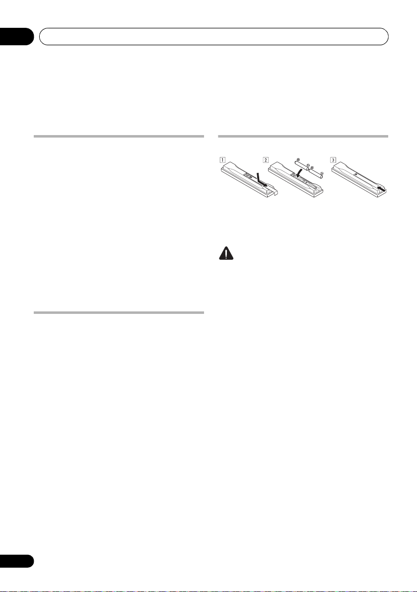
Loading the batteries
The batteries included with the unit are to
check initial operations; they may not last over
a long period. We recommend using alkaline
batteries that have a longer life.
CAUTION
Incorrect use of batteries may result in such
hazards as leakage and bursting. Observe the
following precautions:
• Never use new and old batteries together.
• Insert the plus and minus sides of the
batteries properly according to the marks
in the battery case.
• Batteries with the same shape may have
different voltages. Do not use different
batteries together.
• When disposing of used batteries, please
comply with governmental regulations or
environmental public instruction’s rules
that apply in your country or area.
• WARNING
Do not use or store batteries in direct
sunlight or other excessively hot place,
such as inside a car or near a heater. This
can cause batteries to leak, overheat,
explode or catch fire. It ca n also reduce the
life or performance of batteries.
8
En
Controls and displays 02
SPEAKERS
AUTO/ALC/DIRECT STEREO STANDARD
LISTENING MODE
ADV SURROUND DIRECT CONTROL
iPod iPhone
CONTROL ON/OFFMULTI-ZONE
PQLS HDMI BAND TUNER EDITiPhone
iPod
MCACC
ADVANCED
TUNE
TUNE
PRESET PRESET
ENTER
PHONES
INPUT
SELECTOR
STANDBY/ON
PHASE
CONTROL
MASTER
VOLUME
MCACC
SETUP MIC
AUDIO/VIDEO MULTI-CHANNEL RECEIVER
VSX
-1020
VIDEO CAMERA
iPod
iPhone
USB HDMI 5
MCACC
SETUP MIC
VIDEO 2 INPUT
AUDIOLRVIDEO
iPod
iPhone
USB
12 73 5 8
10
11 1412 13
14 16 13
15
49
6
VSX-1020/VSX-1025
VSX-920
Chapter 2:
Controls and displays
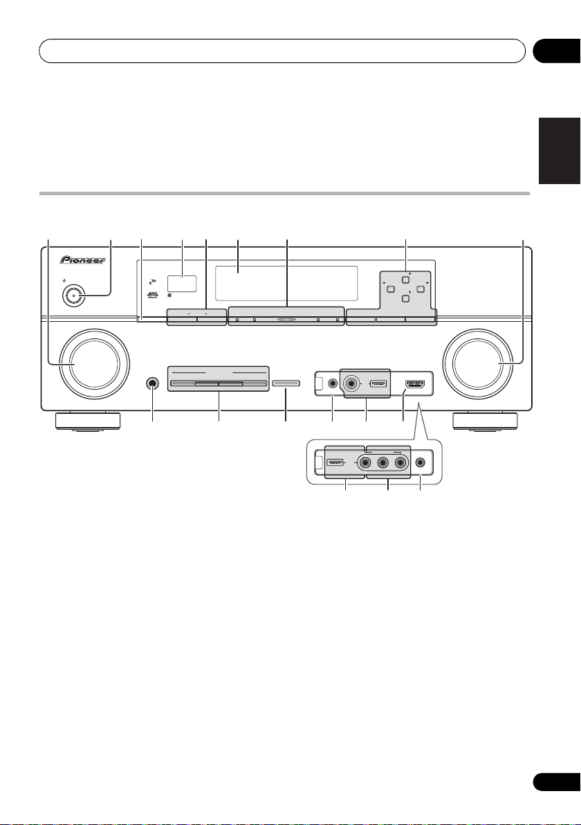
Front panel
1
INPUT SELECTOR
Select an input function.
2
STANDBY/ON
Switches the receiver between on and standby.
3
SPEAKERS
See Switching the speaker terminals on
page 73.
4 Remote sensor
Receives the signals from the remote control
(see Operating range of remote control unit on
page 14).
dial
5
MULTI-ZONE
If you’ve made MULTI-ZONE connections (see
MULTI-ZONE setup on page 32) use these
controls to control the sub zone from the main
zone (see Using the MULTI-ZONE controls on
page 73).
6 Character display
See Display on page 11.
7Indicators
ADVANCED MCACC
set to
ON
PQLS – Lights when the PQLS feature is
active (page 66).
HDMI – Blinks when connecting an HDMI-
equipped component; lights when the
component is connected (page 25).
controls
in the
AUDIO PARAMETER
– Lights when EQ is
menu.
English
Deutsch
Français
Italiano
Nederlands
Español
9
En

Controls and displays02
iPod/iPhone – Lights to indicate iPod/
iPhone is connected (page 45).
8 Tuner controls
BAND – Switches between the AM and FM
radio bands (page 50).
TUNER EDIT –
PRESET /
name stations for recall
TUNE / –
(page 50)
PRESET / – Find preset stations
(page 50).
9
MASTER VOLUME
10
PHONES
Connect the headphones. When the
headphones are connected, there is no sound
output from the speakers.
11 Listening mode buttons
AUTO/ALC/DIRECT – Switches between
Auto Surround (page 57), Auto Level
Control mode and Stream Direct mode
(page 60).
STEREO – Switches between stereo
playback and Front Stage Surround
Advance modes (page 60).
STANDARD – Press for Standard decoding
and to switch between the various 2 Pro
Logic IIx and Neo:6 options (page 57).
ADV SURROUND – Switch between the
various surround modes (page 59).
12
iPod iPhone DIRECT CONTROL
Change the receiver’s input to the iPod and
enable iPod operations on the iPod (page 46).
13
MCACC SETUP MIC
Connect the supplied microphone (page 39).
14
iPod/iPhone/USB
Connect your Apple iPod as an audio and video
source, or connect a USB device for audio and
photo playback (page 35, 36).
Use with
and
ENTER
Find radio frequencies
.
dial
jack
jack
terminals
TUNE /
to memorize and
(page 50)
,
.
15
VSX-1020/VSX-1025 only:
connector
Use for connection to a compatible HDMI
device (Video camera, etc.)(page 34).
16
VSX-920 only:
Use to connect your portable equipment such
as camcorders, video games and portable
audio/video equipment (page 35).
VIDEO 2 INPUT terminals
HDMI input
10
En
Controls and displays 02
SIRIUS
PCM
HDMI
DIGITAL
ANALOG
L C R
SL SR
XL XR
XC
LFE
AUTO
DIGITAL PLUS
AUTO SURROUND
STREAM DIRECT
PROLOGIC x
Neo:6
ADV.SURROUND
STEREO STANDARD
SP AB
SLEEP
DSD PCM
DTS HD ES 96/24
MSTR
S.RTRV SOUND UP MIX
OVER
MONO
dB
2
MULTI-ZONE STEREO
TrueHD WMA9Pro
TUNED
RDS
PQLS
ALC
ATT
2
2
USB
VIDEO
TV
DVD
HDMI
DVR
BD
CD
TUNER
CD-R
iPod
[ 2 ]
[ 3 ]
[ 4 ]
21 3 9754 108
11
12 13
18 1915 16 17
14
7
6
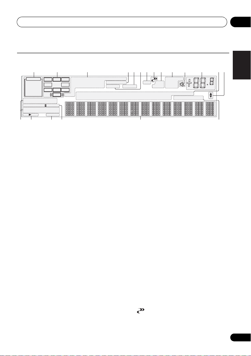
Display
1
SIGNAL
indicators
Light to indicate the currently selected input
signal. AUTO lights when the receiver is set to
select the input signal automatically (page 61).
2 Program format indicators
Light to indicate the channels to which digital
signals are being input.
L/R – Left front/Right front channel
C – Center channel
SL/SR – Left surround/Right surround channel
LFE
– Low frequency effects channel (the
indicators light when an LFE signal is being input)
XL/XR – Two channels other than the ones above
XC – Either one channel other than the ones
above, the mono surround channel or matrix
encode flag
3 Digital format indicators
Light when a signal encoded in the
corresponding format is detected.
2
DIGITAL
– Lights with Dolby Digital decoding.
TrueHD
– Lights with Dolby TrueHD decoding.
– Lights with DTS decoding.
2 DIGITAL PLUS – Lights with Dolby Digital
Plus decoding.
2
DTS
DTS HD – Lights with DTS-HD decoding.
96/24 – Lights with DTS 96/24 decoding.
WMA9 Pro – Lights to indicate that a WMA9 Pro
signal is being decoded.
DSD PCM – Light during DSD (Direct Stream
Digital) to PCM conversion with SACDs.
PCM – Lights during playback of PCM signals.
MSTR – Lights during playback of DTS-HD
Master Audio signal.
4
MULTI-ZONE
Lights when the MULTI-ZONE feature is active
(page 73).
5
SOUND
Lights when any of the Midnight, Loudness or
tone controls feature is selected (page 68).
Lights when Dialog Enhancement is switched on.
6
S.RTRV
Lights when the Sound Retriever function is
(( ))
active (page 69).
7 Listening mode indicators
AUTO SURROUND – Lights when the
Auto Surround feature is switched on
(page 57).
ALC – Lights when the ALC (Auto level
control) mode is selected (page 60).
STREAM DIRECT – Lights when Direct/
Pure Direct is selected (page 60).
ADV.SURROUND – Lights when one of the
Advanced Surround modes has been
selected (page 59).
STEREO – Lights when stereo listening is
switched on (page 59).
STANDARD – Lights when one of the
Standard Surround modes is switched on
(page 57).
8 (PHASE CONTROL)
Lights when Phase Control is switched on
(page 62).
English
Deutsch
Français
Italiano
Nederlands
Español
11
En

Controls and displays02
9 Analog signal indicators
Light to indicate reducing the level of an analog
signal (page 75).
10 Tuner indicators
TUNED – Lights when a broadcast is being
received.
STEREO –
is being received in auto stereo mode.
MONO – Lights when the mono mode is
set using MPX.
RDS – Lights when an RDS broadcast is
received.
11
Lights when the sound is muted (page 14).
12 Master volume level
Shows the overall volume level.
“---” indicates the minimum level, and “+12dB”
indicates the maximum level.
13 Input function indicators
Light to indicate the input function you have
selected.
14 Scroll indicators
Light when there are more selectable items
when making the various settings.
15 Speaker indicators
Indicates the speaker terminal, A and/or B, to
which audio signal output is currently set
(page 73).
16
SLEEP
Lights when the receiver is in sleep mode
(page 75).
17 Matrix decoding format indicators
2PRO LOGIC IIx – This lights to indicate
2 Pro Logic II / 2 Pro Logic IIx decoding
(page 57).
Neo:6 – When one of the Neo:6 modes of
the receiver is on, this lights to indicate
Neo:6 processing (page 57).
18 Character display
Displays various system information.
Lights when a stereo FM broadcast
19 Remote control mode indicator
Lights to indicate the receiver’s remote control
mode setting. (Not displayed when set to 1.)
(page 77)
12
En
Controls and displays 02
RECEIVER
LISTENING MODE
AUTO / ALC /
DIRECT
STEREO
D.ACCESS
CH LEVEL A.ATT DIMMER
SIGNAL SEL
S.RETRIEVER
MCACC SLEEP
MIDNIGHT
TV
/
DTV MPX PQLS
PHASE
CTRL STATUS
PGM
iPod CTRL
HOME
MENU
TUNE
TUNE
TOOLS
LIST
CH
TV CONTROL
INPUT
INPUT
SELECT ZONE 2
iPod
USB TUNER VIDEO TV CTRL
ADAPTERNET RADIO
CDTV
BD DVD
R.SETUP
SOURCERECEIVER
MULTI
OPERATION
DVR/BDR HDMI
RECEIVER
MUTE
MASTER
VOLUME
VOL
PRESET
TOP MENU
BAND GUIDE
T.EDIT
VIDEO
PARAMETER
AUDIO
PARAMETER
ENTER
PRESET
RETURN
PTY
SEARCH
MENU
AUDIO
INFO
CLASS
ENTER
DISP
HDD DVD
546
8
0
79
213
/ CLR
CH
STANDARD ADV SURR
1
2
3
4
8
9
5
6
7
10
11
12
13
14
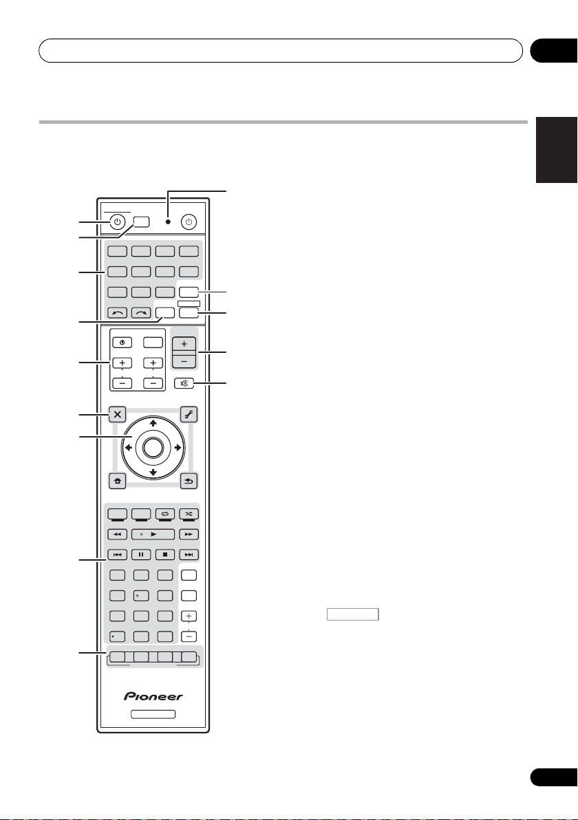
Remote control
This section explains how to operate the
remote control for the receiver.
The remote has been conveniently color-coded
according to component control using the
following system:
• White – Receiver control, TV control
• Blue – Other controls (See page 45, 47, 50,
53, 55 and 83.)
1 RECEIVER
This switches between standby and on for this
receiver.
2
MULTI OPERATION – Use to perform
multi operations (page 81).
R.SETUP – Use to input the preset code
when making remote control settings and
to set the remote control mode (page 77).
3 Input function buttons
Press to select control of other components
(page 77).
4
ZONE 2
Switch to perform operations in the sub zone
(page 74).
5
TV CONTROL
buttons
These buttons are dedicated to control the TV
assigned to the TV CTRL button.
– Turn on/off the power of the TV.
INPUT – Select the TV input signal.
CH +/– – Select channels.
VOL +/– – Adjust the volume on your TV.
6 Receiver controls
Press first to access:
RECEIVER
AUDIO PARAMETER – Use to access the
Audio options (page 68).
VIDEO PARAMETER – Use to access the
Video options (page 71).
HOME MENU – Use to access the Home
Menu (pages 39, 42, 64, 86, 100 and 106).
RETURN – Press to confirm and exit the
current menu screen.
English
Deutsch
Français
Italiano
Nederlands
Español
13
En
Controls and displays02
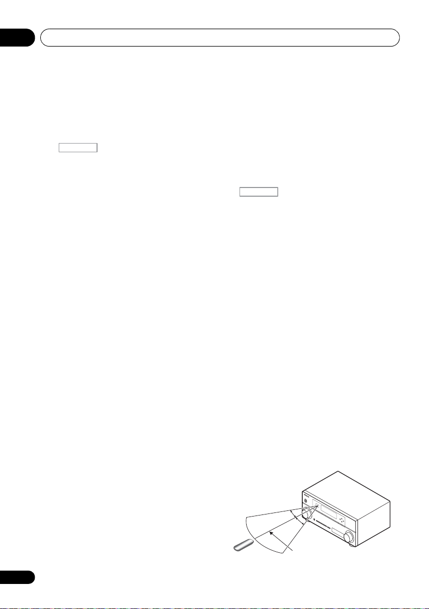
RECEIVER
7 m
30°
30°
14
En
7
///, ENTER
Use the arrow buttons when setting up your
surround sound system (page 86) and the
Audio or Video options (page 68 or 71).
8 Receiver controls
Press first to access:
RECEIVER
PHASE CTRL – S wi tch o n/ of f P ha se Co nt ro l
(page 62).
STATUS – Check selected receiver settings
(page 75).
PQLS – Select the PQLS setting (page 66).
S.RETRIEVER – Press to restore CD quality
sound to compressed audio sources
(page 69).
MIDNIGHT – Switches to Midnight or
Loudness listening (page 68).
SIGNAL SEL – Select an input signal
(page 61).
MCACC – Switch between MCACC presets
(page 61).
SLEEP – Use to put the receiver in sleep
mo de a nd se lec t th e am ount of t ime b efo re
sleep (page 75).
CH LEVEL – Press repeatedly to select a
channel, then use / to adjust the level
(page 103).
A.ATT – Attenuates (lowers) the level of an
analog input signal to prevent distortion
(page 75).
DIMMER – Dims or brightens the display
(page 75).
9 LISTENING MODE controls
AUTO/ALC/DIRECT –
Auto Surround
Control mode and Stream Direct mode
(page 60).
STEREO – Switches between stereo
playback and Front Stage Surround
Advance modes (page 60).
STANDARD – Press for Standard decoding
and to switch between the various 2 Pro
Logic IIx and Neo:6 options (page 57).
Switches between
(page 57)
, Auto Level
ADV SURR – Switch between the various
surround modes (page 59).
10 Remote control LED
Lights when a command is sent from the
remote control (page 77).
11
TV CTRL
Set the preset code of your TV’s manufacturer
when controlling TV (page 78).
12
Switches the remote to control the receiver
(used to select the white commands (SIGNAL
SEL, etc.)).
Switch to perform operations in the main zone.
Also use to set up surround sound.
13
MASTER VOLUME +/–
Set the listening volume.
14
MUTE
Mutes the sound or restores the sound if it has
been muted (adjusting the volume also
restores the sound).
Operating range of remote control unit
The remote control may not work properly if:
• There are obstacles between the remote
control and the receiver’s remote sensor.
• Direct sunlight or fluorescent light is
shining onto the remote sensor.
• The receiver is located near a device that is
emitting infrared rays.
• The receiver is operated simultaneously
with another infrared remote control unit.
Connecting your equipment 03
HDMI
ASSIGNABLE
PB
PR
ASSIGNABLE
ASSIGNABLE
ASSIGNABLE
(
DVD
)
(
DVR/BDR
)
(
DVD
)
Y
P
B
PR
Y
P
B
PR
Y
L
R
R
FRONT CENTER SURROUND
SURROUND BACK
FRONT HEIGHT/WIDE/
LR LR L
RL
ZONE 2
OUT
DVR/BDR
DVD
OUT IN
CD-R/TAPE
OUT ININ
CD
IN
TV/SATINVIDEO
IN
(
DVR/BDR
)
(
OUTPUT 5 V 100 mA MAX
)
(CD)
(
Single
)
SUBWOOFER
(
TV/SAT
)
AM LOOP
FM UNBAL 75
COMPONENT VIDEO
AUDIO
PRE OUT
ANTENNA
OPTICAL
ADAPTER PORT
VIDEO
IR CONTROL
SPEAKERS
SPEAKERS
MONITOR
OUT
LAN
COAXIAL
BD IN IN IN IN IN
OUT
(
10/100
)
IN
1IN2
1
IN
1
IN
2
1 4
2 3 4
IN
1
A
IN
2
B
IN
OUTINOUT
AC IN
VSX-1020/VSX-1025
VSX-920
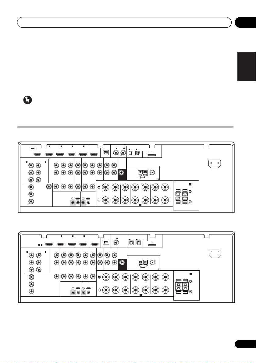
Chapter 3:
Connecting your equipment
This receiver provides you with many connection possibilities, but it doesn’t have to be difficult.
This page explains the kinds of components you can connect to make up your home theater system.
Important
• Illustration shows the VSX-1020, however connections for the VSX-1025 and the VSX-920 are
the same except where noted.
Rear panel
ASSIGNABLE
COAXIAL
LAN
(
)
10/100
IN
1
(
)
DVD
PRE OUT
IN
(
TV/SAT
1
)
IN
(
DVR/BDR
OPTICAL
2
ASSIGNABLE
ADAPTER PORT
(
OUTPUT 5 V 100 mA MAX
)
ANTENNA
SUBWOOFER
CD-R/TAPE
OUT ININ
FRONT CENTER SURROUND
LR LR L
R
SPEAKERS
AM LOOP
A
FM UNBAL 75
SURROUND BACK
)
(
Single
)
FRONT HEIGHT/WIDE/
RL
SPEAKERS
B
COMPONENT VIDEO
ASSIGNABLE
1
IN
(
)
DVD
Y
PB
PR
Y
P
B
PR
HDMI
ASSIGNABLE
1 3
2
IN
(
DVR/BDR
Y
B
P
PR
MONITOR
OUT
1
BD IN IN IN IN
AUDIO
)
L
R
ZONE 2
2 3
DVR/BDR
DVD
OUT IN
OUT
VIDEO
IR CONTROL
IN
OUTINOUT
OUT
CD
TV/SATINVIDEO 1
IN
IN
English
Deutsch
Français
Italiano
Nederlands
Español
AC IN
15
En
Connecting your equipment03
CAUTION
• Before making or changing the
connections, switch off the power and
disconnect the power cord from the power
outlet. Plugging in should be the final step.
Important
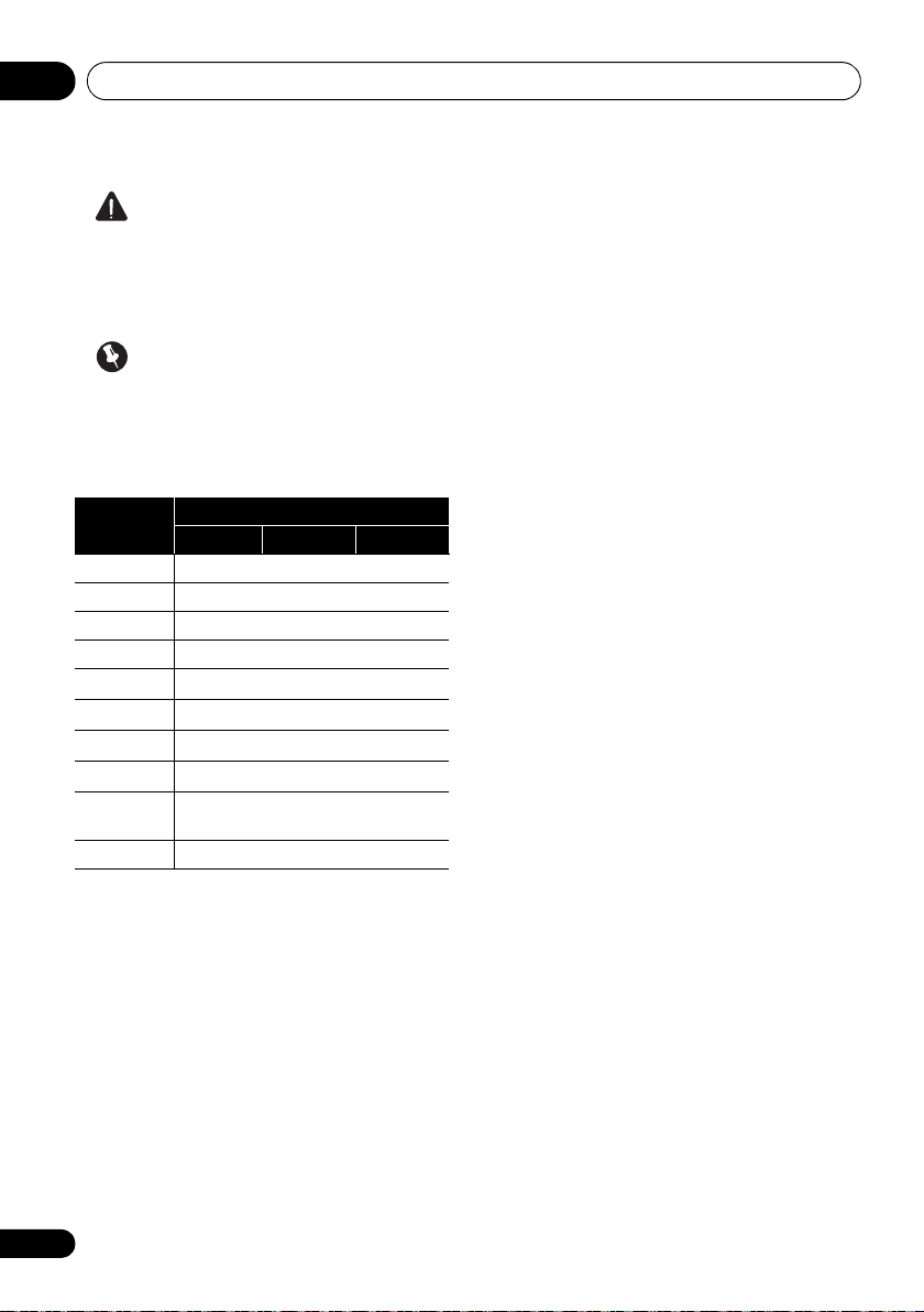
• The input functions below are assigned by
default to the receiver’s different input
terminals. Refer to The Input Setup menu
on page 42 to change the assignments if
other connections are used.
Input
function
DVD COAX-1 IN 1
BD (BD)
TV/SAT OPT-1
DVR/BDR OPT-2 IN 2
HDMI 1
HDMI 2
HDMI 3
a
HDMI 4
a
HDMI 5
(front panel)
CD COAX-2
a. VSX-1020/VSX-1025 only
Input Terminals
Digital HDMI
(HDMI-1)
(HDMI-2)
(HDMI-3)
(HDMI-4)
(HDMI-5)
a
Component
16
En
Connecting your equipment 03
Speaker B
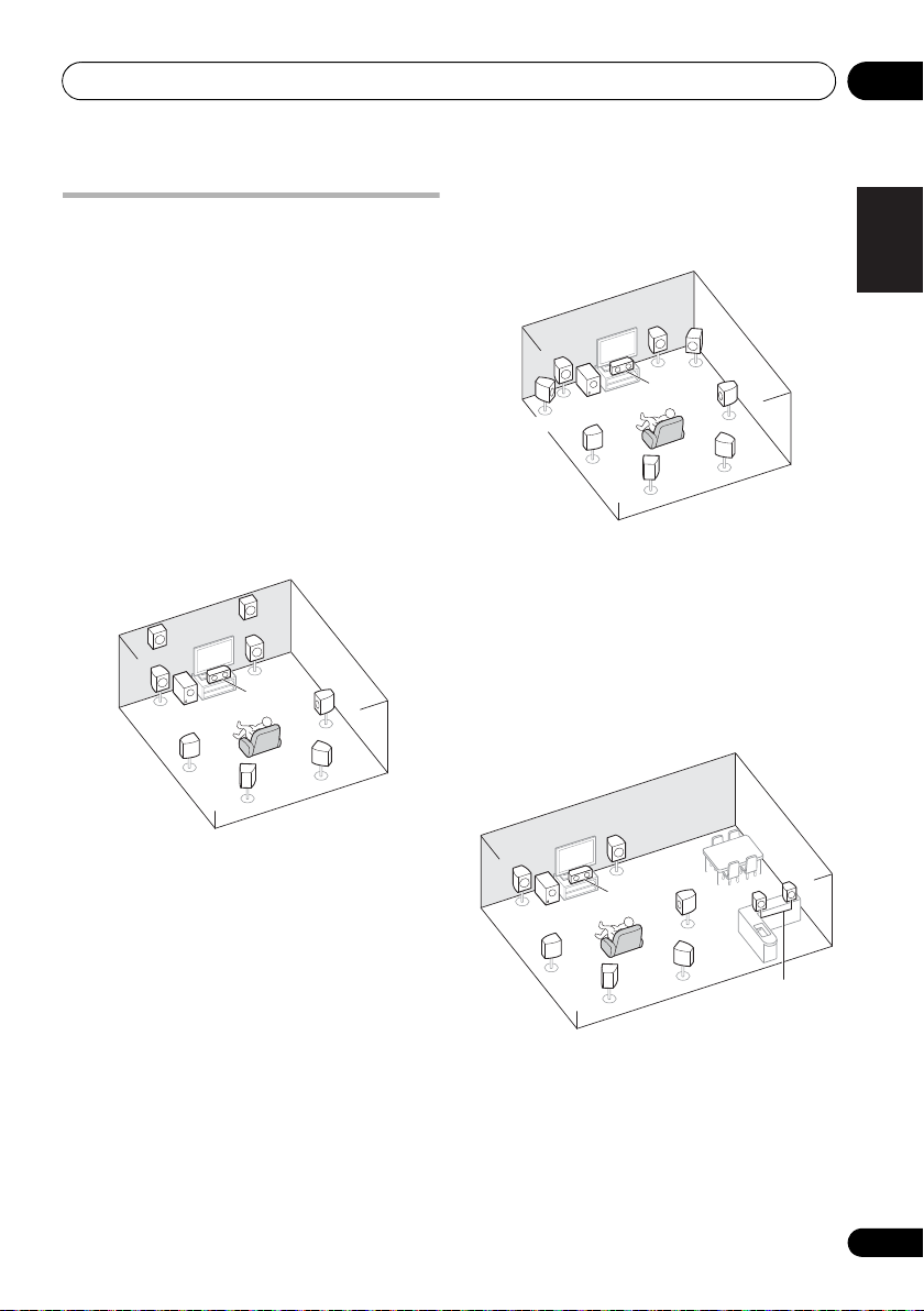
Determining the speakers’ application
This unit permits you to build various surround
systems, in accordance with the number of
speakers you have.
• Be sure to connect speakers to the front
left and right channels (L and R).
• It is also possible to only connect one of the
surround back speakers (SB) or neither.
Choose one from Plans [A] to [E] below.
[A] 9.1 channel surround system (Front height)
*Default setting
• Speaker System setting: Normal(SB/FH)
FHR
FHL
L
SW
SL
A 9.1 ch surround system connects the left and
right front speakers (L/R), the center speaker
(C), the left and right front height speakers
(FHL/FHR), the left and right surround
speakers (SL/SR), the left and right surround
back speakers (SBL/SBR), and the subwoofer
(SW).
This surround system produces a more true-tolife sound from above.
R
C
SBL
SR
SBR
[B] 9.1 channel surround system (Front wide)
•
Speaker System setting: Normal(SB/FW)
R
FWR
C
SBL
SR
SBR
FWL
L
SW
SL
This plan replaces the left and right front
height speakers shown in [A] with the left and
right front wide speakers (FWL/FWR).
This surround system produces a true-to-life
sound over a wider area.
[C] 7.1 channel surround system & Speaker B connection
• Speaker System setting: Speaker B
R
L
SW
SL
C
SBL
SR
SBR
R
L
With these connections you can
simultaneously enjoy 5.1-channel surround
sound in the main zone with stereo playback of
the same sound on the B speakers. The same
connections also allow for 7.1-channel
surround sound in the main zone when not
using the B speakers.
English
Deutsch
Français
Italiano
Nederlands
Español
17
En
Connecting your equipment03
L
R
SL
SW
C
SR
Front Bi-Amp
ZONE 2
Main zone
Sub zone
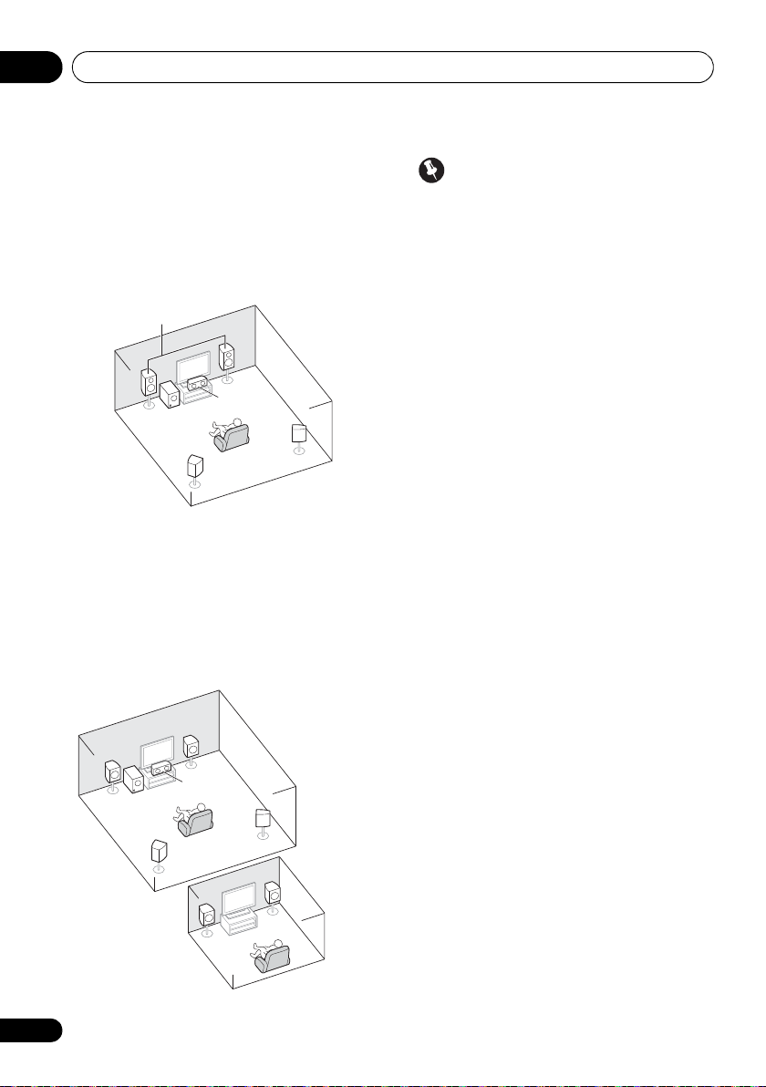
[D] 5.1 channel surround system & Front Bi-amping connection (High quality surround)
• Speaker System setting: Front Bi-Amp
Bi-amping connection of the front speakers for
high sound quality with 5.1-channel surround
sound.
[E] 5.1 channel surround system & ZONE 2 connection (Multi Zone)
• Speaker System setting: ZONE 2
With these connections you can
simultaneously enjoy 5.1-channel surround
sound in the main zone with stereo playback
on another component in ZONE 2 (The
selection of input devices is limited.)
Important
•The Speaker System setting must be
made if you use any of the connections
shown above other than [A] (see Speaker
system setting on page 101).
• Sound does not come through
simultaneously from the front height, front
wide, speaker B and surround back
speakers. Output speakers are different
depending on the input signal or listening
mode.
Other speaker connections
• Your favorite speaker connections can be
selected even if you have fewer than 5.1
speakers (except front left/right speakers).
• When not connecting a subwoofer,
connect speakers with low frequency
reproduction capabilities to the front
channel. (The subwoofer’s low frequency
component is played from the front
speakers, so the speakers could be
damaged.)
• After connecting, be sure to conduct
the Auto MCACC (speaker environment
setting) procedure.
See Automatically conducting optimum
sound tuning (Auto MCACC) on page 39.
18
En
R
L
C
SW
SR
SL
L
R
Connecting your equipment 03
L
SW
C
FHL
FWL
SL
SBL
SBR
SB
SR
FWR
R
FHR
30 30
60
60
60
120 120
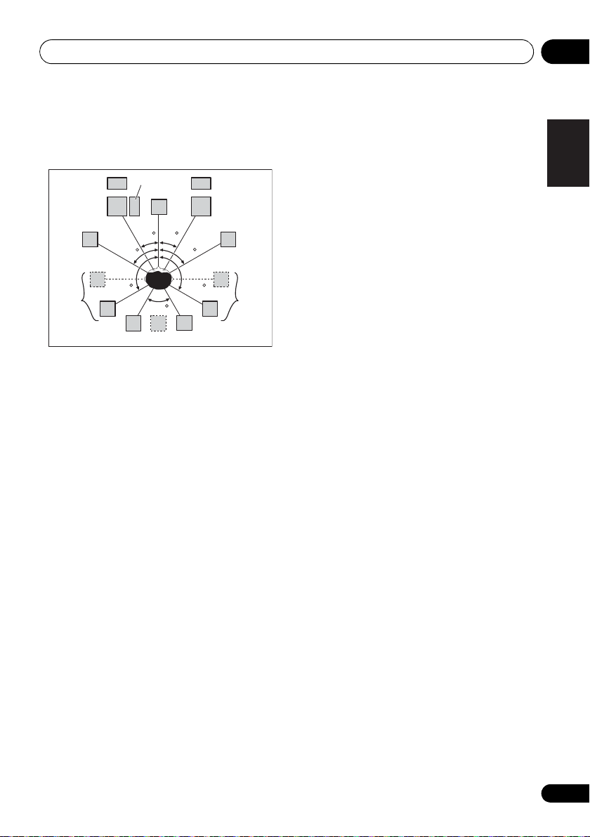
Placing the speakers
Refer to the chart below for placement of the
speakers you intend to connect.
• Place the surround speakers at 120º from
the center. If you, (1) use the surround back
speaker, and, (2) don’t use the front height
speakers / front wide speakers, we
recommend placing the surround speaker
right beside you.
• If you intend to connect only one surround
back speaker, place it directly behind you.
• Place the left and right front height
speakers at least 1 m directly above the left
and right front speakers.
Some tips for improving sound quality
Where you put your speakers in the room has
a big effect on the quality of the sound. The
following guidelines should help you to get the
best sound from your system.
• The subwoofer can be placed on the floor.
Ideally, the other speakers should be at
about ear-level when you’re listening to
them. Putting the speakers on the floor
(except the subwoofer), or mounting them
very high on a wall is not recommended.
• For the best stereo effect, place the front
speakers 2 m to 3 m apart, at equal
distance from the TV.
• If you’re going to place speakers around
your CRT TV, use shielded speakers or
place the speakers at a sufficient distance
from your CRT TV.
• If you’re using a center speaker, place the
front speakers at a wider angle. If not,
place them at a narrower angle.
• Place the center speaker above or below
the TV so that the sound of the center
channel is localized at the TV screen. Also,
make sure the center speaker does not
cross the line formed by the leading edge
of the front left and right speakers.
• It is best to angle the speakers towards the
listening position. The angle depends on
the size of the room. Use less of an angle
for bigger rooms.
• Surround and surround back speakers
should be positioned 60 cm to 90 cm higher
than your ears and tilted slightly downward.
Make sure the speakers don’t face each
other. For DVD-Audio, the speakers should
be more directly behind the listener than for
home theater playback.
• Try not to place the surround speakers
farther away from the listening position
than the front and center speakers. Doing
so can weaken the surround sound effect.
English
Deutsch
Français
Italiano
Nederlands
Español
19
En
Connecting your equipment03
12 3
10 mm
10 mm
Connecting the speakers
Each speaker connection on the receiver
comprises a positive (+) and negative (–)
terminal. Make sure to match these up with the
terminals on the speakers themselves.
CAUTION
• These speaker terminals carry
HAZARDOUS LIVE voltage. To prevent
the risk of electric shock when connecting
or disconnecting the speaker cables,
disconnect the power cord before touching
any uninsulated parts.
• Make sure that all the bare speaker wire is
twisted together and inserted fully into the
speaker terminal. If any of the bare speaker
wire touches the back panel it may cause
the power to cut off as a safety measure.
Bare wire connections
A-Speaker terminals:
1 Twist exposed wire strands together. 2 Loosen terminal and insert exposed wire. 3 Tighten terminal.
Important
• Please refer to the manual that came with
your speakers for details on how to connect
the other end of the speaker cables to your
speakers.
• Use an RCA cable to connect the subwoofer.
It is not possible to connect using speaker
cables.
CAUTION
• Make sure that all speakers are securely
installed. This not only improves sound
quality, but also reduces the risk of
damage or injury resulting from speakers
being knocked over or falling in the event of
external shocks such as earthquakes.
B-Speaker terminals:
1 Twist exposed wire strands together.
2 Push open the tabs and insert exposed wire.
3 Release the tabs.
12 3
20
En
Connecting your equipment 03
HDMI
ASSIGNABLE
P
B
P
R
ASSIGNABLE
ASSIGNABLE
ASSIGNABLE
(
DVD
)
(
DVR/BDR
)
(
DVD
)
Y
P
B
P
R
Y
P
B
P
R
Y
L
R
R
FRONT CENTER SURROUND
SURROUND BACK
FRONT HEIGHT/WIDE/
LR LR L
RL
ZONE 2
OUT
DVR/BDR
DVD
OUT IN
CD-R/TAPE
OUT ININ
CD
IN
TV/SATINVIDEO
IN
(
DVR/BDR
)
(
OUTPUT 5 V 100 mA MAX
)
(CD)
(
Single
)
SUBWOOFER
(
TV/SAT
)
AM LOOP
FM UNBAL 75
COMPONENT VIDEO
AUDIO
PRE OUT
ANTENNA
OPTICAL
ADAPTER PORT
VIDEO
IR CONTROL
SPEAKERS
SPEAKERS
MONITOR
OUT
LAN
COAXIAL
BD IN IN IN IN IN
OUT
(
10/100
)
IN
1IN2
1
IN
1
IN
2
1 4
2 3 4
IN
1
A
IN
2
B
IN
OUTINOUT
AC IN
LINE LEVEL
INPUT
Front left
Subwoofer
Center
Surround right
Surround back left
Surround back right
Front right
Surround left
7.1 ch surround setting
Not connected
Surround back
6.1 ch surround setting
Not connected
5.1 ch surround setting
Not connected
Speaker B - left
Speaker B - right
Speaker B setting
Front wide left
Front wide right
Front height left
Front height setting
Front height right
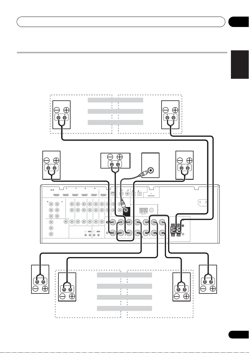
The front height terminals can also be used for
the front wide and Speaker B speakers.
Front wide setting
ZONE 2 setting
ZONE 2 - left
ZONE 2 - right
The surround back terminals
can also be used for ZONE2.
VSX-1020/VSX-1025
Installing your speaker system
At the very least, front left and right speakers only are necessary. Note that your main surround
speakers should always be connected as a pair, but you can connect just one surround back
speaker if you like (it must be connected to the left surround back terminal).
English
Deutsch
Français
Italiano
Nederlands
Español
21
En
Connecting your equipment03
HDMI
ASSIGNABLE
PB
PR
ASSIGNABLE
ASSIGNABLE
ASSIGNABLE
(
DVD
)
(
DVR/BDR
)
(
DVD
)
Y
P
B
PR
Y
P
B
PR
Y
L
R
R
FRONT CENTER SURROUND
SURROUND BACK
FRONT HEIGHT/WIDE/
LR LR L
RL
ZONE 2
OUT
DVR/BDR
DVD
OUT IN
CD-R/TAPE
OUT ININ
CD
IN
TV/SATINVIDEO
IN
(
DVR/BDR
)
(
OUTPUT 5 V 100 mA MAX
)
(CD)
(
Single
)
SUBWOOFER
(
TV/SAT
)
AM LOOP
FM UNBAL 75
COMPONENT VIDEO
AUDIO
PRE OUT
ANTENNA
OPTICAL
ADAPTER PORT
VIDEO
IR CONTROL
SPEAKERS
SPEAKERS
MONITOR
OUT
LAN
COAXIAL
BD IN IN IN IN IN
OUT
(
10/100
)
IN
IN
1IN2
1
IN
1
IN
2
1 4
2 3 4
IN
1
A
IN
2
B
IN
OUTINOUT
High
Low
High
Low
AC IN
Front left
Subwoofer
Center
Surround right
Front right
Surround left
Bi-amp compatible
speaker
Bi-amp compatible
speaker
VSX-1020/VSX-1025
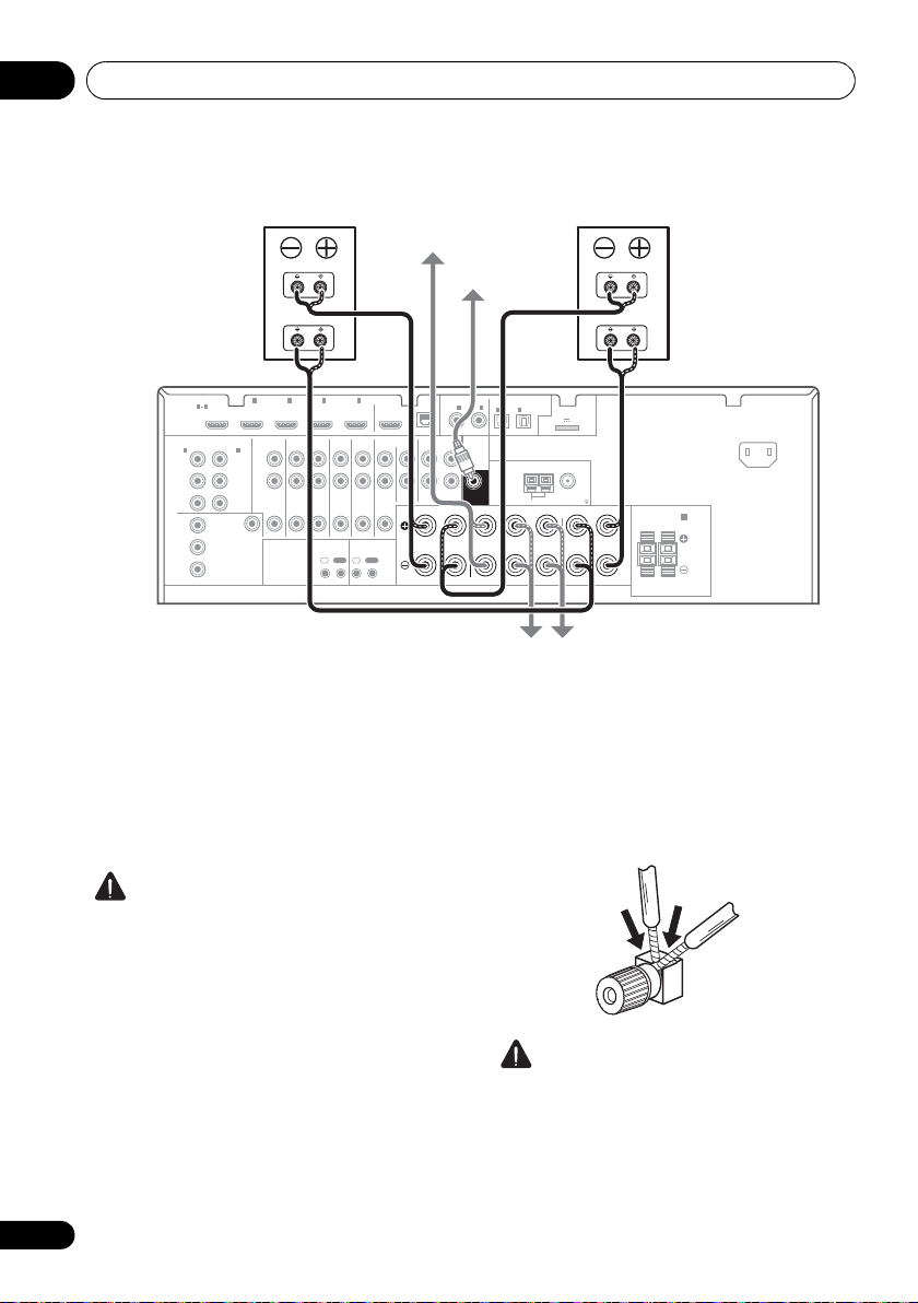
Bi-amping your speakers
Bi-amping is when you connect the high
frequency driver and low frequency driver of
your speakers to different amplifiers for better
crossover performance. Your speakers must be
bi-ampable to do this (having separate
terminals for high and low) and the sound
improvement will depend on the kind of
speakers you’re using.
CAUTION
• Most speakers with both High and Low
terminals have two metal plates that
connect the High to the Low terminals.
These must be removed when you are biamping the speakers or you could severely
damage the amplifier. See your speaker
• If your speakers have a removable
22
En
manual for more information.
crossover network, make sure you do not
remove it for bi-amping. Doing so may
damage your speakers.
Bi-wiring your speakers
Your speakers can also be bi-wired if they
support bi-amping.
• With these connections, the Speaker
System setting makes no difference.
• To bi-wire a speaker, connect two speaker
cords to the speaker terminal on the receiver.
• Don’t connect different speakers from the
• When bi-wiring as well, heed the cautions
CAUTION
same terminal in this way.
for bi-amping shown at the left.

Connecting your equipment 03
Selecting the Speaker system
The front height terminals can be used for front
wide and Speaker B connections, in addition to
for the front height speakers. Also, the
surround back terminals can be used for biamping and ZONE 2 connections, in addition
to for the surround back speakers. Make this
setting according to the application.
Front height setup
*Default setting
1 Connect a pair of speakers to the front height speaker terminals.
See Connecting the speakers on page 20.
2 If necessary, select ‘
the
Speaker System
See Speaker system setting on page 101 to do
this.
Front wide setup
1 Connect a pair of speakers to the front height speaker terminals.
See Connecting the speakers on page 20.
2 Select ‘
Speaker System
See Speaker system setting on page 101 to do
this.
Normal(SB/FW)
Speaker B setup
You can listen to stereo playback in another
room.
1 Connect a pair of speakers to the front height speaker terminals.
See Connecting the speakers on page 20.
2 Select ‘
System
See Speaker system setting on page 101 to do
this.
Speaker B
menu.
menu.
menu.
’ from the
Normal(SB/FH)
’ from the
Speaker
’ from
Bi-Amping setup
Bi-amping connection of the front speakers for
high sound quality with 5.1-channel surround
sound.
1 Connect a Bi-amp compatible speakers to the front and surround back speaker terminals.
See Bi-amping your speakers on page 22.
2 Select ‘
System
See Speaker system setting on page 101 to do
this.
Front Bi-Amp
menu.
’ from the
Speaker
ZONE 2 setup
With these connections you can
simultaneously enjoy 5.1-channel surround
sound in the main zone with stereo playback
on another component in ZONE 2.
1 Connect a pair of speakers to the surround back speaker terminals.
See Connecting the speakers on page 20.
2 Select ‘
System
See Speaker system setting on page 101 to do
this.
ZONE 2
menu.
’ from the
Speaker
English
Deutsch
Français
Italiano
Nederlands
Español
23
En
Connecting your equipment03
Note
High picture quality
Terminal for
connection with
source device
Terminal for
connection with TV
monitor
Video signals can be output
This product incorporates copyright protection
technology that is protected by U.S. patents and other
intellectual property rights. Use of this copyright
protection technology must be authorized by Rovi
Corporation, and is intended for home and other limited
viewing uses only unless otherwise authorized by Rovi
Corporation. Reverse engineering or disassembly is
prohibited.
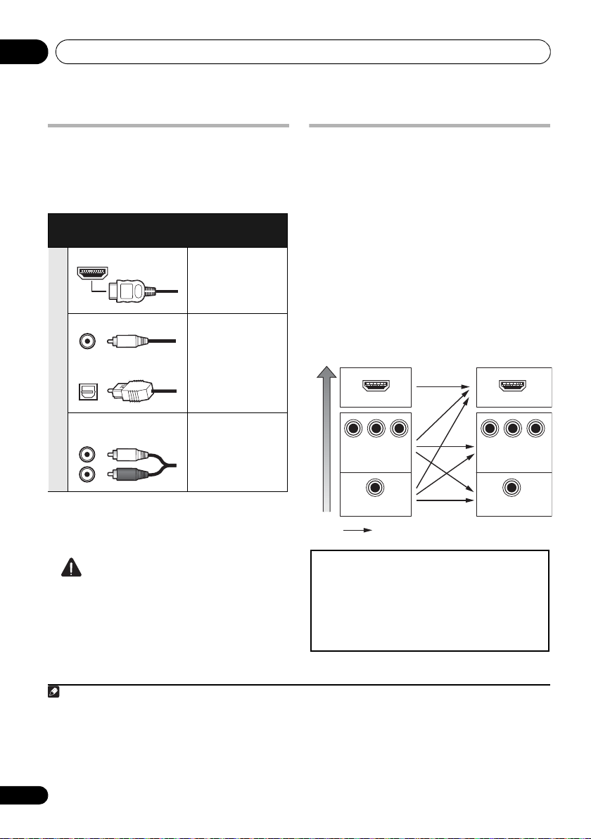
About the
audio connection
There are several types of audio input and output
terminals on this receiver. The receiver selects
the first available signal in the following order
when you choose
Types of cables and
AUTO
terminals
as the input signal:
Transferable
audio signals
HDMI HD audio
Digital (Coaxial) Conventional
digital audio
Digital (Optical)
Sound signal priority
RCA (Analog)
(White/Red)
Conventional analog audio
• With an HDMI cable, video and audio
signals can be transferred in high quality
over a single cable.
About the video converter
The video converter ensures that all video
sources are output through all of the
MONITOR OUT jacks. The only exception is
HDMI: since this resolution cannot be
downsampled, you must connect your
monitor/TV to the receiver’s HDMI video
outputs when connecting this video source.
If several video components are assigned to
the same input function (see The Input Setup
menu on page 42), the converter gives priority
to HDMI, component, then composite (in that
order).
HDMI IN
P
P
B
VIDEO IN
VIDEO IN
R
Y
COMPONENT VIDEO
MONITOR OUT
MONITOR OUT
Y
COMPONENT
HDMI OUT
P
B
VIDEO
1
P
R
CAUTION
• When connecting optical cables, be careful
when inserting the plug not to damage the
shutter protecting the optical socket.
• When storing optical cable, coil loosely.
The cable may be damaged if bent around
sharp corners.
1 • If the video signal does not appear on your TV, try adjusting the resolution settings on your component or display.
Note that some components (such as video game units) have resolutions that may not be converted. In this case, try
switching Digital Video Conversion (in Setting the Video options on page 71) OFF.
• The signal input resolutions that can be converted from the component video input for the HDMI output are 480i/
576i, 480p/576p, 720p and 1080i. 1080p signal cannot be converted.
• Only signals with an input resolution of 480i/576i can be converted from the component video input for the
composite MONITOR OUT terminals.
24
En
Connecting your equipment 03
T
A
HDMI IN
HDMI OUT HDMI OUT
DIGITAL OUT
OPTICAL
ANALOG
RL
AUDIO OUT
Other HDMI/DVIequipped component
HDMI/DVI-compatible
Blu-ray disc player
HDMI/DVI-compatible TV
Select one
This connection is
required in order to
listen to the sound of
the TV over the receiver.
VSX-1020/
VSX-1025
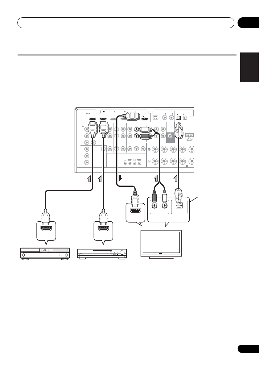
Connecting your TV and playback components
Connecting using HDMI
If you have an HDMI or DVI (with HDCP) equipped component (BD: Blu-ray disc player, etc.), you
can connect it to this receiver using a commercially available HDMI cable.
If the TV and playback components support the Control with HDMI function, the convenient
Control with HDMI functions can be used (see Control with HDMI function on page 63).
1
BD IN IN IN IN IN
HDMI
ASSIGNABLE
1 4
COMPONENT VIDEO
1
IN
(
)
DVD
Y
P
B
P
R
Y
P
B
P
R
ASSIGNABLE
MONITOR
OUT
VIDEO
IN
(
DVR/BDR
Y
P
P
AUDIO
2
)
L
R
B
R
2 3 4
ZONE 2
DVR/BDR
OUT IN
OUT
DVD
IR CONTROL
IN
OUTINOUT
TV/SATINVIDEO
OUT
CD
IN
IN
ASSIGNABLE
LAN
COAXIAL
(
)
10/100
IN
1IN2
IN
(
)
(CD)
DVD
PRE OUT
SUBWOOFER
CD-R/TAPE
OUT ININ
FRONT CENTER SURROUND
LR
R
IN
1
(
)
TV/SAT
ANTENNA
SPEAKERS
2
(
DVR/BDR
OPTICAL
ASSIGNABLE
)
AM LOOP
A
(
OUTPU
English
Deutsch
Français
Italiano
Nederlands
Español
• For input components, connections other
than HDMI connections are also possible
(see Connecting your DVD player with no
HDMI output on page 27).
• If you want to listen to the sound of the TV
over the receiver, connect the receiver and
TV with audio cables.
25
En

Connecting your equipment03
Note
About HDMI
1
The HDMI connection transfers
uncompressed digital video, as well as almost
every kind of digital audio that the connected
component is compatible with, including DVDVideo, DVD-Audio, SACD, Dolby Digital Plus,
Dolby TrueHD, DTS-HD Master Audio (see
below for limitations), Video CD/Super VCD
and CD. See About the video converter on
page 24 for more on HDMI compatibility.
This receiver incorporates High-Definition
Multimedia Interface (HDMI
This receiver supports the functions described
below through HDMI connections.
®
) technology.
2
• Digital transfer of uncompressed video
(contents protected by HDCP (1080p/24,
1080p/60, etc.))
• 3D signal transfer
• Deep Color signal transfer
• x.v.Color signal transfer
3
3
3
• Input of multi-channel linear PCM digital
audio signals (192 kHz or less) for up to 8
channels
• Input of the following digital audio
formats:
4
– Dolby Digital, Dolby Digital Plus, DTS,
High bitrate audio (Dolby TrueHD, DTS-HD
Master Audio, DTS-HD High Resolution
Audio), DVD-Audio, CD, SACD (DSD
signal), Video CD, Super VCD
• Synchronized operation with components
using the Control with HDMI function (see
Control with HDMI function on page 63).
HDMI, the HDMI Logo and High-Definition
Multimedia Interface are trademarks or
regis tered trad emark s of H DM I L ice nsin g, LLC i n
the United States and other countries.
“x.v.Color” and x.v.Color logo are trademarks of
Sony Corporation.
1 • An HDMI connection can only be made with DVI-equipped components compatible with both DVI and High
Bandwidth Digital Content Protection (HDCP). If you choose to connect to a DVI connector, you will need a separate
adaptor (DVIHDMI) to do so. A DVI connection, however, does not support audio signals. Consult your local audio
dealer for more information.
• If you connect a component that is not compatible with HDCP, an HDCP ERROR message is displayed on the front
panel display. Some components that are compatible with HDCP still cause this message to be displayed, but so long
as there is no problem with displaying video this is not a malfunction.
• Depending on the component you have connected, using a DVI connection may result in unreliable signal transfers.
This receiver supports SACD,
•
these formats, however, make sure that the component connected to this receiver also supports the corresponding
format.
2 • Use a High Speed HDMI® cable. If an HDMI cable other than a High Speed HDMI® cable is used, it may not work
properly.
• When an HDMI cable with a built-in equalizer is connected, it may not operate properly.
3 Signal transfer is only possible when connected to a compatible component.
4 • HDMI format digital audio transmissions require a longer time to be recognized. Due to this, interruption in the
audio may occur when switching between audio formats or beginning playback.
• Turning on/off the device connected to this unit's HDMI OUT terminal during playback, or disconnecting/
connecting the HDMI cable during playback, may cause noise or interrupted audio.
Dolby Digital Plus, Dolby TrueHD
and
DTS-HD Master Audio
. To take advantage of
26
En
Connecting your equipment 03
L
5
D
HDMI IN
DIGITAL OUT
COAXIAL OPTICAL
ANALOG
RL
AUDIO OUT
VIDEO OUT
Y
P
B
PR
COMPONENT VIDEO OUT
DIGITAL OUT
OPTICAL
ANALOG
RL
AUDIO OUT
DVD player etc.
HDMI/DVI-compatible TV
Select one
Select one
Select one
This connection is
required in order to
listen to the sound of
the TV over the receiver.
VSX-1020/
VSX-1025
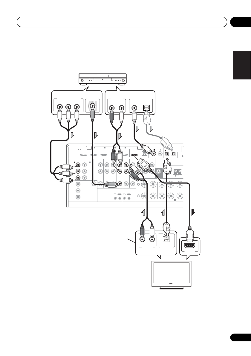
Connecting your DVD player with no HDMI output
This diagram shows connections of a TV (with HDMI input) and DVD player (or other playback
component with no HDMI output) to the receiver.
ASSIGNABLE
LAN
COAXIAL
(
)
10/100
IN
1IN2
(
)
(CD)
DVD
PRE OUT
SUBWOOFER
CD-R/TAPE
OUT ININ
FRONT CENTER SURROUND
LR
R
IN
1
(
TV/SAT
ANTENNA
SPEAKERS
OPTICAL
ASSIGNABLE
IN
2
A
(
OUTPUT
(
)
)
DVR/BDR
AM LOOP
F
A
1
IN
(
DVR/BDR
Y
P
P
VIDEO
2
B
R
AUDIO
)
L
R
2 3 4
ZONE 2
DVR/BDR
OUT IN
OUT
DVD
IR CONTROL
IN
OUTINOUT
TV/SATINVIDEO
OUT
CD
IN
IN
BD IN IN IN IN IN
HDMI
ASSIGNABLE
1 4
COMPONENT VIDEO
ASSIGNABLE
1
IN
(
)
DVD
Y
P
B
P
R
Y
B
P
P
R
MONITOR
OUT
English
Deutsch
Français
Italiano
Nederlands
Español
• If you want to listen to the sound of the TV over the receiver, connect the receiver and TV with
audio cables.
• If the connection was made using an optical cable, you’ll need to tell the receiver which digital
input you connected the DVD player to (see The Input Setup menu on page 42).
27
En
Connecting your equipment03
U
DVD player etc.
TV
Select one
Select one
Select one
Select one
This connection is
required in order to
listen to the sound of
the TV over the receiver.
VSX-1020/
VSX-1025
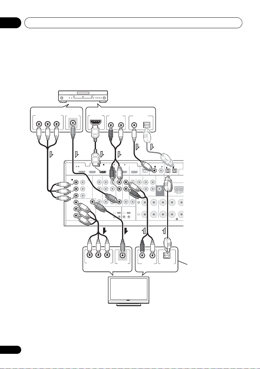
Connecting your TV with no HDMI input
This diagram shows connections of a TV (with no HDMI input) and DVD player (or other playback
component) to the receiver.
• With these connections, the picture is not output to the TV even if the DVD player is connected with
an HDMI cable. Connect the DVD player’s video signals using a composite or component cord.
• If the connection was made
using an optical cable, you’ll
need to tell the receiver which
COMPONENT VIDEO OUT
PR
B
P
VIDEO OUT
Y
HDMI OUT
AUDIO OUT
ANALOG
RL
DIGITAL OUT
COAXIAL OPTICAL
digital input you connected
the DVD player to (see The
Input Setup menu on page 42).
1
AUDIO
2
IN
(
)
DVR/BDR
L
Y
R
P
B
ZONE 2
OUT
PR
VIDEO
PR
B
P
COMPONENT VIDEO IN
2 3 4
DVR/BDR
DVD
OUT IN
IR CONTROL
IN
OUTINOUT
Y
VIDEO IN
TV/SATINVIDEO
OUT
CD
IN
IN
BD IN IN IN IN IN
HDMI
ASSIGNABLE
1 4
COMPONENT VIDEO
ASSIGNABLE
1
IN
(
)
DVD
Y
PB
PR
MONITOR
OUT
Y
P
B
PR
• Connect using an HDMI cable to listen to HD audio on the receiver. Do not use an HDMI cable
to input video signals.
Depending on the video component, it may not be possible to output signals connected by
HDMI and other methods simultaneously, and it may be necessary to make output settings.
ASSIGNABLE
LAN
COAXIAL
(
)
10/100
IN
1IN2
IN
(
)
(CD)
DVD
PRE OUT
SUBWOOFER
CD-R/TAPE
OUT ININ
FRONT CENTER SURROUND
LR
R
RL
ANALOG
AUDIO OUT
OPTICAL
DIGITAL OUT
1
(
)
TV/SAT
ANTENNA
SPEAKERS
IN
2
(
DVR/BDR
OPTICAL
ASSIGNABLE
)
AM LOOP
A
(
OUTP
Please refer to the operating instructions supplied with your component for more information.
28
En
Connecting your equipment 03
U
X
R
STB
Select one
VSX-1020/VSX-1025
E
P
ANALOG
RL
AUDIO IN
VIDEO IN
ANALOG
RL
AUDIO OUT
VIDEO OUT
DIGITAL OUT
COAXIAL OPTICAL
HDD/DVD recorder, VCR, etc.
Select one
VSX-1020/VSX-1025
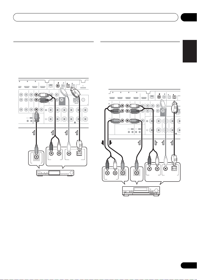
Connecting a satellite/cable receiver or other set-top box
Satellite and cable receivers, and terrestrial
digital TV tuners are all examples of so-called
‘set-top boxes’.
2 3 4
DVR/BDR
OUT IN
IN IN
DVD
IR CONTROL
IN
OUTINOUT
TV/SATINVIDEO
VIDEO OUT
OUT
IN
ASSIGNABLE
COAXIAL
LAN
(
)
10/100
IN1IN
(
)
(CD)
DVD
PRE OUT
SUBWOOFER
CD
CD-R/TAPE
OUT ININ
IN
FRONT CENTER SURROUND
R
LR LR
RL
ANALOG
AUDIO OUT
2
IN
IN
1
2
(
(
)
DVR/BDR
TV/SAT
ANTENNA
SPEAKERS
COAXIAL OPTICAL
DIGITAL OUT
OPTICAL
ASSIGNABLE
ADAPTER PO
(
OUTPUT 5 V 100 mA MA
)
AM LOOP
FM UNBAL 75
A
SURRO
Connecting a HDD/DVD recorder, VCR and other video sources
This receiver has two sets of audio/video
inputs and outputs suitable for connecting
analog or digital video devices, including
HDD/DVD recorders and VCRs.
122 3 4
IN IN IN IN
AUDIO
)
R/BDR
L
R
B
ZONE 2
DVR/BDR
OUT IN
OUT
R
EO
DVD
TV/SATINVIDEO
IR CONTROL
IN
OUTINOUT
OUT
IN
ASSIGNABLE
LAN
COAXIAL
(
)
10/100
IN
1IN2
(
)
(CD)
DVD
PRE OUT
SUBWOOFER
CD
CD-R/TAPE
OUT ININ
IN
FRONT CENTER SURROUND
R
LR
IN
1
(
)
TV/SAT
ANTENNA
SPEAKERS
IN
(
DVR/BDR
OPTICAL
2
AM LOOP
ASSIGNABL
)
A
(
OUT
English
Deutsch
Français
Italiano
Nederlands
Español
• If the connection was made using a coaxial
cable, you’ll need to tell the receiver which
digital input you connected the set-top box
to (see The Input Setup menu on page 42).
• If the connection was made using a coaxial
cable, you’ll need to tell the receiver which
digital input you connected the recorder to
(see The Input Setup menu on page 42).
• In order to record, you must connect the
analog audio cables (the digital connection
is for playback only).
29
En
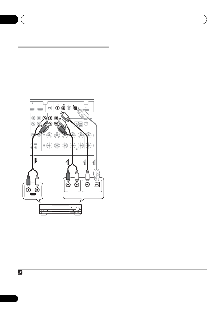
Connecting your equipment03
D
ANALOG
RL
AUDIO OUT
DIGITAL OUT
COAXIAL OPTICAL
RL
AUDIO IN
REC
CD-R, MD, DAT, etc.
Select one
VSX-1020/VSX-1025
Note
Connecting other audio components
This receiver has both digital and analog
inputs, allowing you to connect audio
components for playback.
One of these inputs have corresponding outputs
for use with analog audio recorders.
4
IN
TV/SATINVIDEO
CONTROL
IN
OUT
OUT
CD
IN
ASSIGNABLE
LAN
COAXIAL
(
)
10/100
IN
1IN2
(
)
(CD)
DVD
PRE OUT
SUBWOOFER
CD-R/TAPE
OUT IN
IN
FRONT CENTER SURROUND
R
LR LR
IN
1
(
TV/SAT
ANTENNA
SPEAKERS
OPTICAL
IN
2
(
)
DVR/BDR
AM LOOP
ASSIGNABLE
ADAPTER PORT
(
OUTPUT 5 V 100 mA MAX
)
FM UNBAL 75
A
)
SURROUN
• If your turntable has line-level outputs (i.e.,
it has a built-in phono pre-amp), connect it
to the CD inputs instead.
• If you’re connecting a recorder, connect
the analog audio outputs to the analog
audio inputs on the recorder.
About the WMA9 Pro decoder
This unit has an on-board Windows Media™
Audio 9 Professional
it is possible to playback WMA9 Pro-encoded
audio using HDMI, coaxial or optical digital
connection when connected to a WMA9 Procompatible player. However, the connected
DVD player, set-top box, etc. must be able to
output WMA9 Pro format audio signals
through a coaxial or optical digital output.
1
(WMA9 Pro) decoder, so
• If the connection was made using an
optical cable, you’ll need to tell the receiver
which digital input you connected the
component to (see The Input Setup menu
on page 42).
1• Windows Media and the Windows logo are trademarks or registered trademarks of Microsoft Corporation in the United
States and/or other countries.
30
En
• With WMA9 Pro, sound problems may occur depending on your computer system. Note that WMA9 Pro 96 kHz
sources will be downsampled to 48 kHz.
Loading...