


VSX-1020-K
Table of contents
 Loading...
2010
VSX-1020-K
For details, refer to "Important Check Points for good servicing".
AUDIO/VIDEO MULTI-CHANNEL RECEIVER
VSX-1020-K
VSX-1025-K
THIS MANUAL IS APPLICABLE TO THE FOLLOWING MODEL(S) AND TYPE(S).
Model Type Power Requirement Remarks
VSX-1020-K UXCNCB AC 120 V
VSX-1025-K CUXCN AC 120 V
ORDER NO.
RRV4045
PIONEER CORPORATION 1-1, Shin-ogura, Saiwai-ku, Kawasaki-shi, Kanagawa 212-0031, Japan
PIONEER ELECTRONICS (USA) INC. P.O. Box 1760, Long Beach, CA 90801-1760, U.S.A.
PIONEER EUROPE NV Haven 1087, Keetberglaan 1, 9120 Melsele, Belgium
PIONEER ELECTRONICS ASIACENTRE PTE. LTD. 253 Alexandra Road, #04-01, Singapore 159936
PIONEER CORPORATION
K-IZK MAR.
2010 Printed in Japan
1
1. SAFETY PRECAUTIONS
The following check should be performed for the
continued protection of the customer and service
technician.
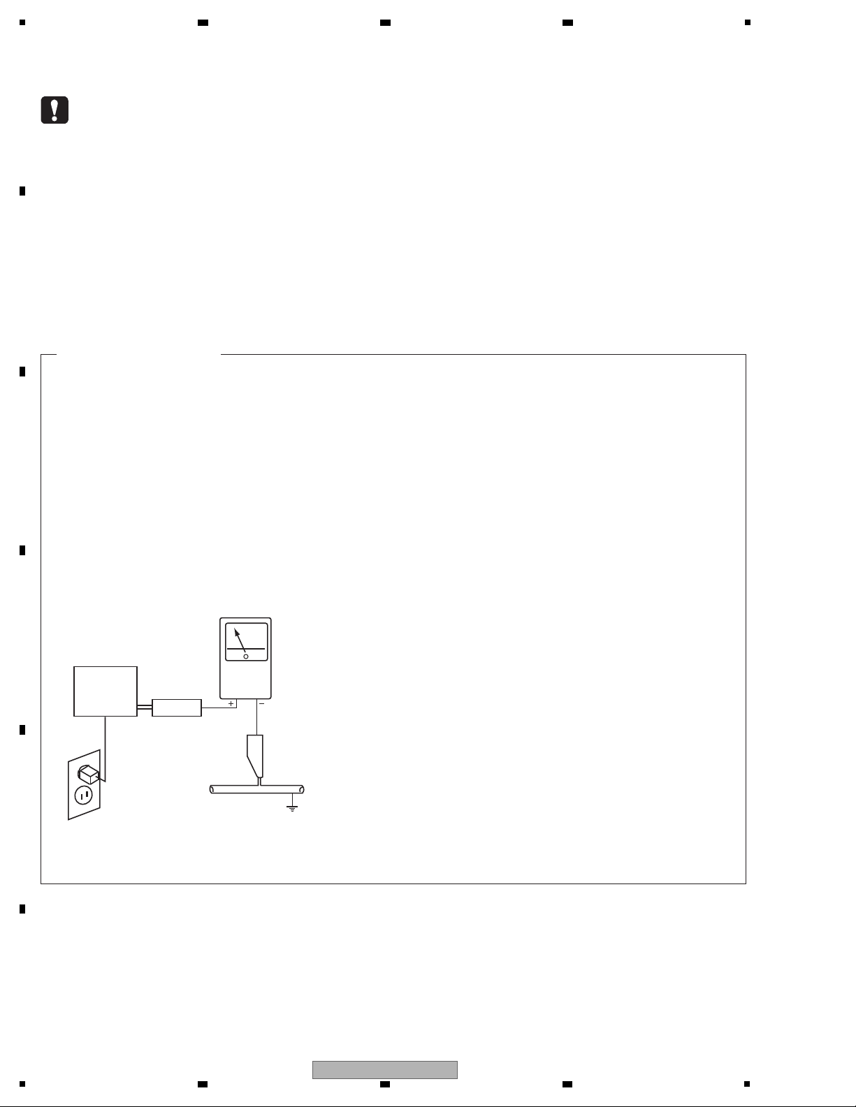
LEAKAGE CURRENT CHECK
Measure leakage current to a known earth ground
(water pipe, conduit, etc.) by connecting a leakage
current tester such as Simpson Model 229-2 or
equivalent between the earth ground and all exposed
metal parts of the appliance (input/output terminals,
screwheads, metal overlays, control shaft, etc.). Plug
the AC line cord of the appliance directly into a 120V
AC 60 Hz outlet and turn the AC power switch on. Any
current measured must not exceed 0.5 mA.
ANY MEASUREMENTS NOT WITHIN THE LIMITS
OUTLINED ABOVE ARE INDICATIVE OF A POTENTIAL
SHOCK HAZARD AND MUST BE CORRECTED BEFORE
RETURNING THE APPLIANCE TO THE CUSTOMER.
2. PRODUCT SAFETY NOTICE
Many electrical and mechanical parts in the appliance
have special safety related characteristics. These are
often not evident from visual inspection nor the protection
afforded by them necessarily can be obtained by using
replacement components rated for voltage, wattage, etc.
Replacement parts which have these special safety
characteristics are identified in this Service Manual.
Electrical components having such features are
identified by marking with a > on the schematics and on
the parts list in this Service Manual.
The use of a substitute replacement component which
does not have the same safety characteristics as the
PIONEER recommended replacement one, shown in the
parts list in this Service Manual, may create shock, fire,
or other hazards.
Product Safety is continuously under review and new
instructions are issued from time to time. For the latest
information, always consult the current PIONEER Service
Manual. A subscription to, or additional copies of,
PIONEER Service Manual may be obtained at a nominal
charge from PIONEER.
Leakage
current
tester
Reading should
not be above
0.5 mA
Device
under
test
Test all
exposed metal
surfaces
Also test with
plug reversed
(Using AC adapter
plug as required)
Earth
ground
AC Leakage Test
(FOR USA MODEL ONLY)
WARNING
This product may contain a chemical known to the State of California to cause cancer, or birth defects or other reproductive
harm.
Health & Safety Code Section 25249.6 - Proposition 65
This service manual is intended for qualified service technicians ; it is not meant for the casual do-ityourselfer. Qualified technicians have the necessary test equipment and tools, and have been trained
to properly and safely repair complex products such as those covered by this manual.
Improperly performed repairs can adversely affect the safety and reliability of the product and may
void the warranty. If you are not qualified to perform the repair of this product properly and safely, you
should not risk trying to do so and refer the repair to a qualified service technician.
2 3 4
SAFETY INFORMATION
A
B
C
D
E
F
2
1
2 3 4
VSX-1020-K
5
[Important Check Points for Good Servicing]
In this manual, procedures that must be performed during repairs are marked with the below symbol.
Please be sure to confirm and follow these procedures.
1. Product safety
Please conform to product regulations (such as safety and radiation regulations), and maintain a safe servicing environment by
following the safety instructions described in this manual.
1 Use specified parts for repair.
Use genuine parts. Be sure to use important parts for safety.
2 Do not perform modifications without proper instructions.
Please follow the specified safety methods when modification(addition/change of parts) is required due to interferences such as
radio/TV interference and foreign noise.
3 Make sure the soldering of repaired locations is properly performed.
When you solder while repairing, please be sure that there are no cold solder and other debris.
Soldering should be finished with the proper quantity. (Refer to the example)
4 Make sure the screws are tightly fastened.
Please be sure that all screws are fastened, and that there are no loose screws.
5 Make sure each connectors are correctly inserted.
Please be sure that all connectors are inserted, and that there are no imperfect insertion.
6 Make sure the wiring cables are set to their original state.
Please replace the wiring and cables to the original state after repairs.
In addition, be sure that there are no pinched wires, etc.
7 Make sure screws and soldering scraps do not remain inside the product.
Please check that neither solder debris nor screws remain inside the product.
8 There should be no semi-broken wires, scratches, melting, etc. on the coating of the power cord.
Damaged power cords may lead to fire accidents, so please be sure that there are no damages.
If you find a damaged power cord, please exchange it with a suitable one.
9 There should be no spark traces or similar marks on the power plug.
When spark traces or similar marks are found on the power supply plug, please check the connection and advise on secure
connections and suitable usage. Please exchange the power cord if necessary.
a Safe environment should be secured during servicing.
When you perform repairs, please pay attention to static electricity, furniture, household articles, etc. in order to prevent injuries.
Please pay attention to your surroundings and repair safely.
2. Adjustments
To keep the original performance of the products, optimum adjustments and confirmation of characteristics within specification.
Adjustments should be performed in accordance with the procedures/instructions described in this manual.
4. Cleaning
For parts that require cleaning, such as optical pickups, tape deck heads, lenses and mirrors used in projection monitors, proper
cleaning should be performed to restore their performances.
3. Lubricants, Glues, and Replacement parts
Use grease and adhesives that are equal to the specified substance.
Make sure the proper amount is applied.
5. Shipping mode and Shipping screws
To protect products from damages or failures during transit, the shipping mode should be set or the shipping screws should be
installed before shipment. Please be sure to follow this method especially if it is specified in this manual.
6 7 8
A
B
C
D
5
VSX-1020-K
6 7 8
E
F
3

1
2 3 4
CONTENTS
SAFETY INFORMATION ..........................................................................................................................................................2
1. SERVICE PRECAUTIONS ....................................................................................................................................................5
A
B
C
D
E
F
1.1 NOTES ON SOLDERING ...............................................................................................................................................5
1.2 NOTES ON REPLACING PARTS ...................................................................................................................................5
1.3 CAUTION ........................................................................................................................................................................5
2. SPECIFICATIONS .................................................................................................................................................................6
2.1 SPECIFICATIONS...........................................................................................................................................................6
2.2 PANEL FACILITIES .........................................................................................................................................................7
3. BASIC ITEMS FOR SERVICE.............................................................................................................................................11
3.1 CHECK POINTS AFTER SERVICING..........................................................................................................................11
3.2 PCB LOCATIONS .........................................................................................................................................................12
3.3 JIGS LIST......................................................................................................................................................................13
4. BLOCK DIAGRAM...............................................................................................................................................................14
4.1 OVERALL WIRING DIAGRAM......................................................................................................................................14
4.2 DIGITAL AUDIO BLOCK DIAGRAM..............................................................................................................................16
4.3 ANALOG AUDIO BLOCK DIAGRAM ............................................................................................................................18
4.4 DIGITAL VIDEO BLOCK DIAGRAM..............................................................................................................................19
4.5 ANALOG VIDEO BLOCK DIAGRAM ............................................................................................................................20
4.6 GND BLOCK DIAGRAM ...............................................................................................................................................22
5. DIAGNOSIS.........................................................................................................................................................................25
5.1 DIAGNOSIS FLOWCHART...........................................................................................................................................25
5.2 ERROR INDICATIONS..................................................................................................................................................40
6. SERVICE MODE .................................................................................................................................................................41
6.1 TEST MODE .................................................................................................................................................................41
7. DISASSEMBLY ....................................................................................................................................................................43
8. EACH SETTING AND ADJUSTMENT ................................................................................................................................50
8.1 HOW TO UPDATE FIRMWARE ....................................................................................................................................50
8.2 IDLE CURRENT ADJUSTMENT ..................................................................................................................................53
9. EXPLODED VIEWS AND P
ARTS LIST...............................................................................................................................54
9.1 PACKING SECTION......................................................................................................................................................54
9.2 EXTERIOR SECTION...................................................................................................................................................56
10. SCHEMATIC DIAGRAM ....................................................................................................................................................60
10.1 AUDIO ASSY ..............................................................................................................................................................60
10.2 COMPONENT ASSY ..................................................................................................................................................62
10.3 COMPOSITE, MIC, F-VIDEO and BRIDGE2 ASSYS.................................................................................................64
10.4 F-HDMI, USB MTG and HDMI MTG ASSYS ..............................................................................................................66
10.5 AMP ASSY..................................................................................................................................................................68
10.6 DISPLAY, HEADPHONE and POWER SW ASSYS....................................................................................................70
10.7 D-MAIN ASSY (1/12) ..................................................................................................................................................72
10.8 D-MAIN ASSY (2/12) ..................................................................................................................................................78
10.9 D-MAIN ASSY (3/12) ..................................................................................................................................................80
10.10 D-MAIN ASSY (4/12) ................................................................................................................................................82
10.11 D-MAIN ASSY
(5/12) ................................................................................................................................................84
10.12 D-MAIN ASSY (6/12) ................................................................................................................................................86
10.13 D-MAIN ASSY (7/12) ................................................................................................................................................88
10.14 D-MAIN ASSY (8/12) ................................................................................................................................................90
10.15 D-MAIN ASSY (9/12) ................................................................................................................................................92
10.16 D-MAIN ASSY (10/12) ..............................................................................................................................................94
10.17 D-MAIN ASSY (11/12) ..............................................................................................................................................96
10.18 D-MAIN ASSY (12/12) ..............................................................................................................................................98
10.19 MAIN and BRIDGE1 ASSYS ..................................................................................................................................100
11. PCB CONNECTION DIAGRAM ......................................................................................................................................102
11.1 AUDIO ASSY ............................................................................................................................................................102
11.2 COMPONENT ASSY
................................................................................................................................................104
11.3 COMPOSITE, MIC, F-VIDEO and BRIDGE2 ASSYS...............................................................................................106
11.4 F-HDMI, USB MTG and HDMI MTG ASSYS ............................................................................................................108
11.5 AMP ASSY................................................................................................................................................................110
11.6 DISPLAY, HEADPHONE and POWER SW ASSYS..................................................................................................114
11.7 D-MAIN ASSY...........................................................................................................................................................118
11.8 MAIN ASSY...............................................................................................................................................................122
11.9 BRIDGE1, GUIDE3 GIUIDE-L and GUIDE-R ASSYS ..............................................................................................126
12. PCB PARTS LIST ............................................................................................................................................................128
4
1
2 3 4
VSX-1020-K
5
• For environmental protection, lead-free solder is used on the printed circuit boards mounted in this unit.
Be sure to use lead-free solder and a soldering iron that can meet specifications for use with lead-free solders for repairs
accompanied by reworking of soldering.
• Compared with conventional eutectic solders, lead-free solders have higher melting points, by approximately 40 ºC.
Therefore, for lead-free soldering, the tip temperature of a soldering iron must be set to around 373 ºC in general, although
the temperature depends on the heat capacity of the PC board on which reworking is required and the weight of the tip of
the soldering iron.
Do NOT use a soldering iron whose tip temperature cannot be controlled.
Compared with eutectic solders, lead-free solders have higher bond strengths but slower wetting times and higher melting
temperatures (hard to melt/easy to harden).
The following lead-free solders are available as service parts:
• Parts numbers of lead-free solder:
GYP1006 1.0 in dia.
GYP1007 0.6 in dia.
GYP1008 0.3 in dia.
The part listed below is difficult to replace as a discrete component part.
When the part listed in the table is defective, replace whole Assy.
EMMA2RL2 UPD61283F1-407LU2A BGA
IC1501 HDMI Receiver SII9233ACTU IC with heat-pad
Assy Name
D-MAIN Assy
IC800
7028069261010-IL
PCB Assy Part No.
Ref No. Function Part No.
Parts that is Difficult to Replace
Remarks
• Discharging
For more detail, please refer to “7. DISASSEMBLY - 1. Discharging”.
• Notes on Ground Points Connection
For more detail, please refer to “7. DISASSEMBLY - 2. Notes on Ground Points Connection”.
6 7 8
1. SERVICE PRECAUTIONS
1.1 NOTES ON SOLDERING
A
B
1.2 NOTES ON REPLACING PARTS
1.3 CAUTION
C
D
E
F
VSX-1020-K
5
6 7 8
5
1
iPod cable
(L308102013010-IL)
Accessories
Remote control
(8300759500010-IL)
AM loop antenna
(ATB7013)
FM wire antenna
(ADH7030)
Dry cell batteries
(AAA size IEC R03) x2
Microphone (for Auto MCACC setup)
(APM7008)
(VSX-1020-K)
(VSX-1025-K)
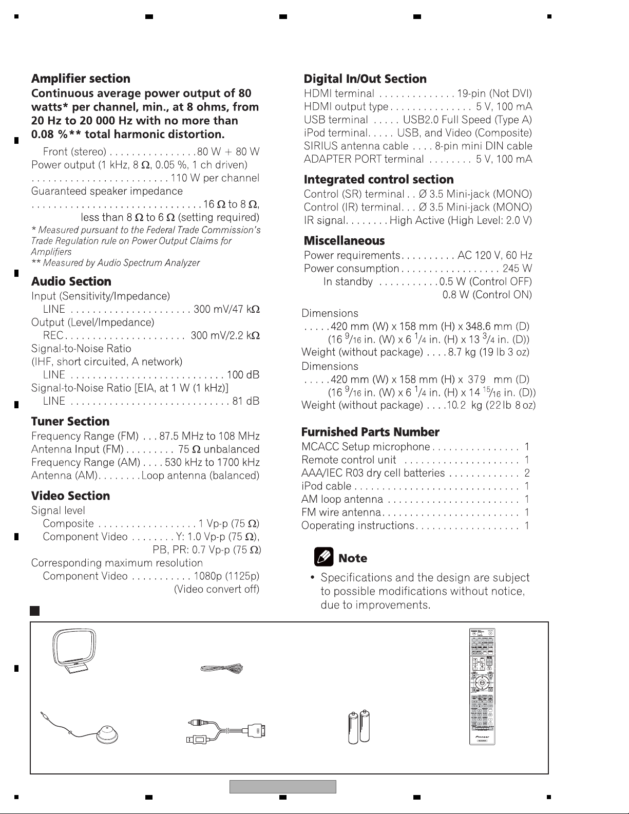
2. SPECIFICATIONS
2.1 SPECIFICATIONS
A
B
2 3 4
C
D
E
F
6
1
2 3 4
VSX-1020-K
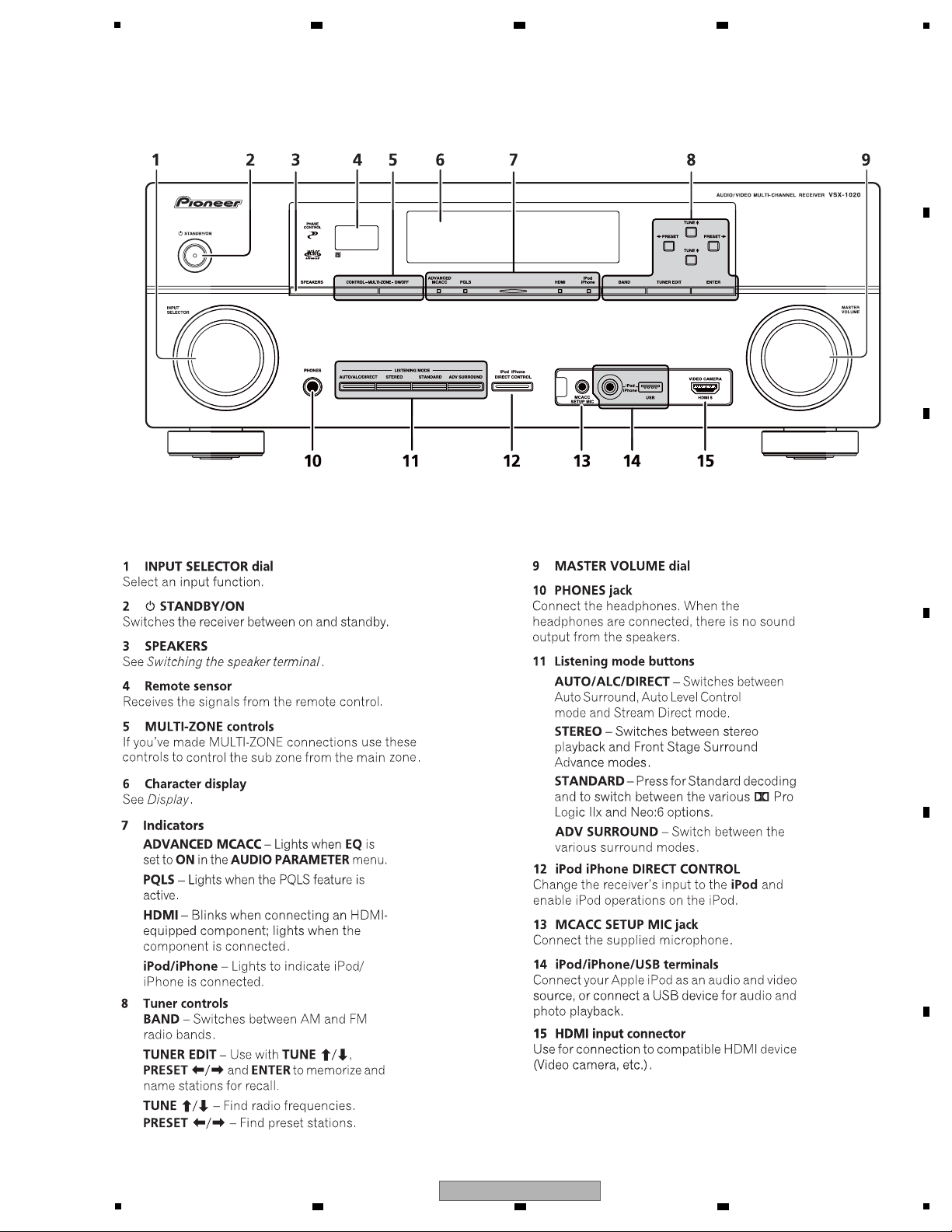
Front panel
5
2.2 PANEL FACILITIES
6 7 8
A
B
C
D
E
F
VSX-1020-K
5
6 7 8
7
A
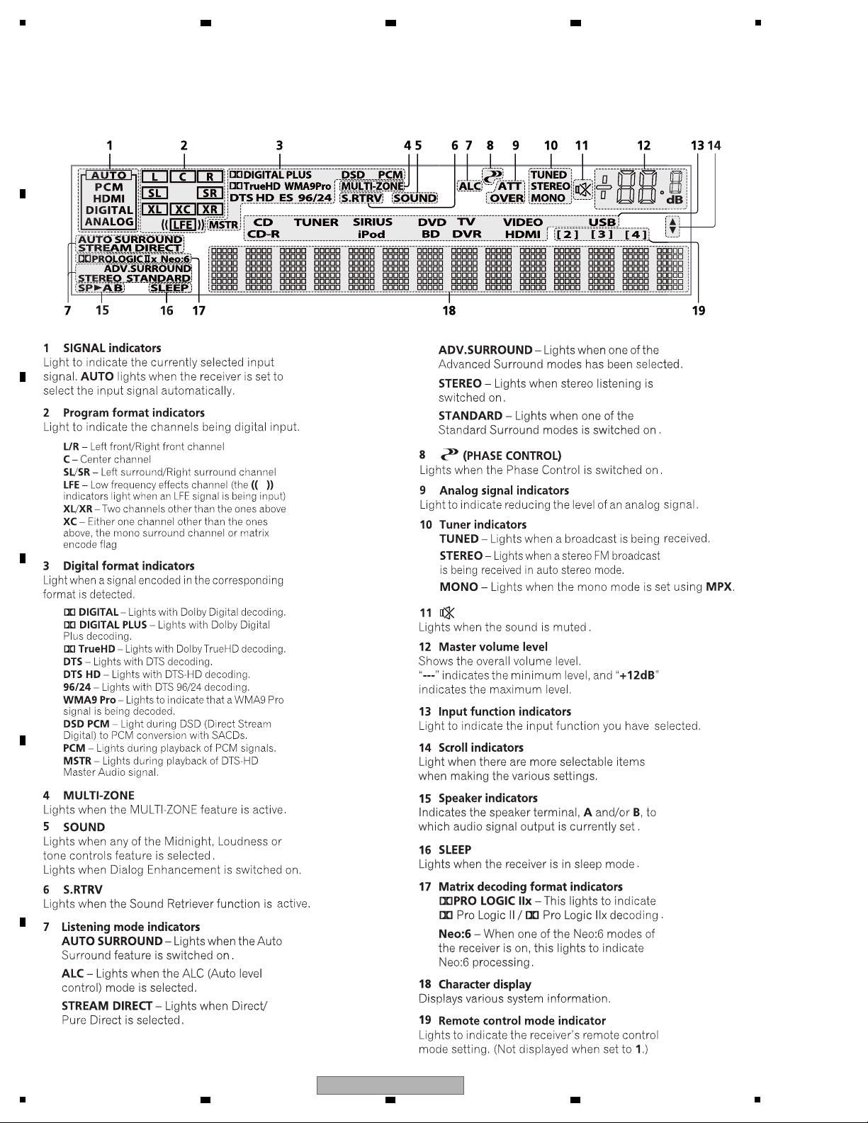
Display
B
1
2 3 4
C
D
E
F
8
1
2 3 4
VSX-1020-K
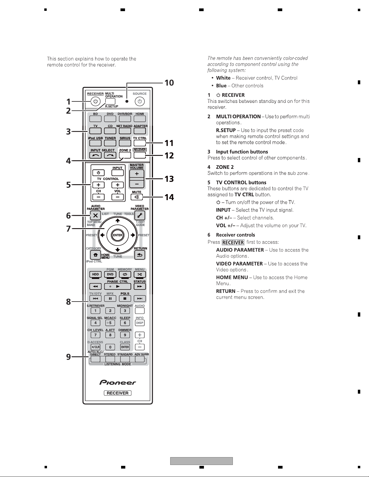
Remote control
5
6 7 8
A
B
C
D
E
F
VSX-1020-K
5
6 7 8
9
1
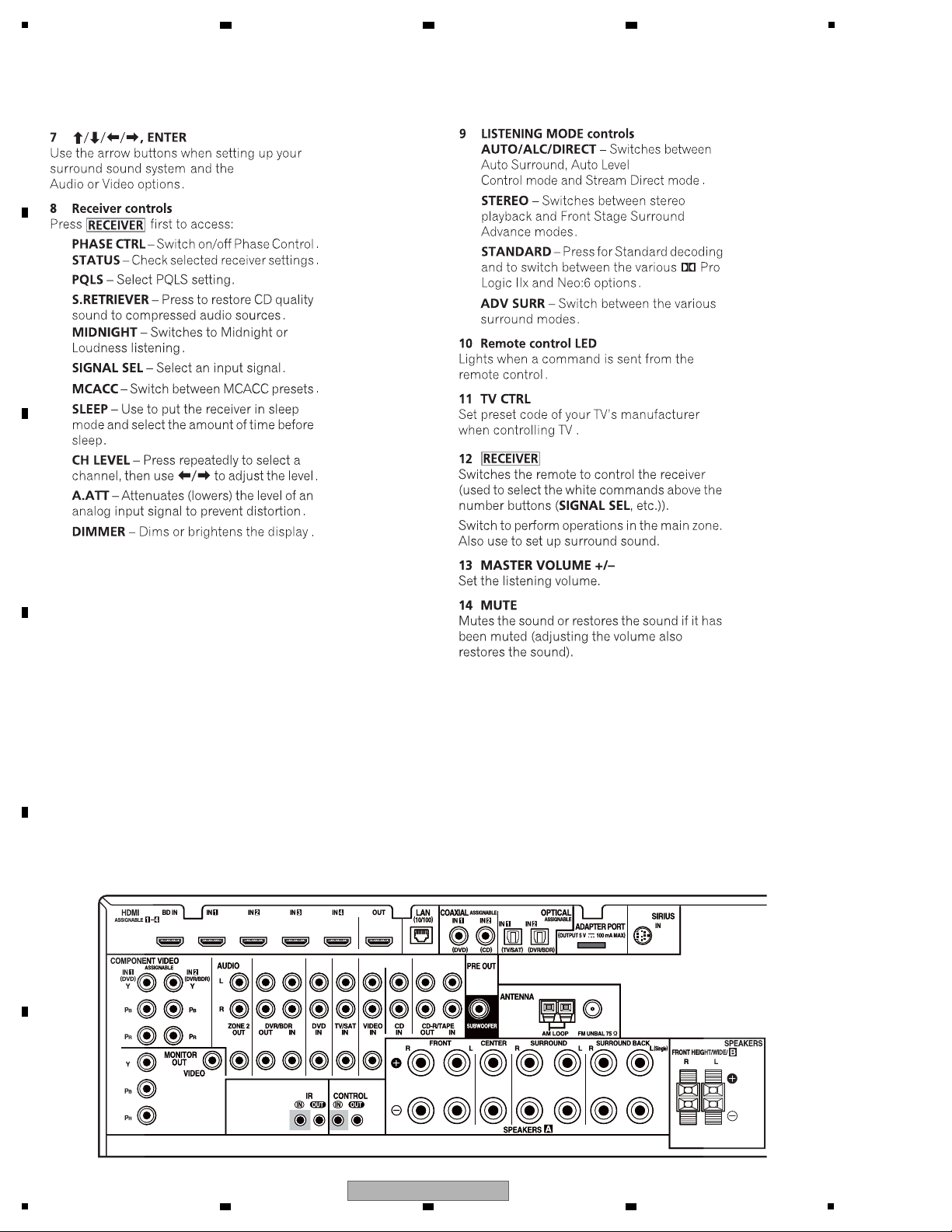
Rear panel
A
B
2 3 4
C
D
E
F
10
1
2 3 4
VSX-1020-K
5
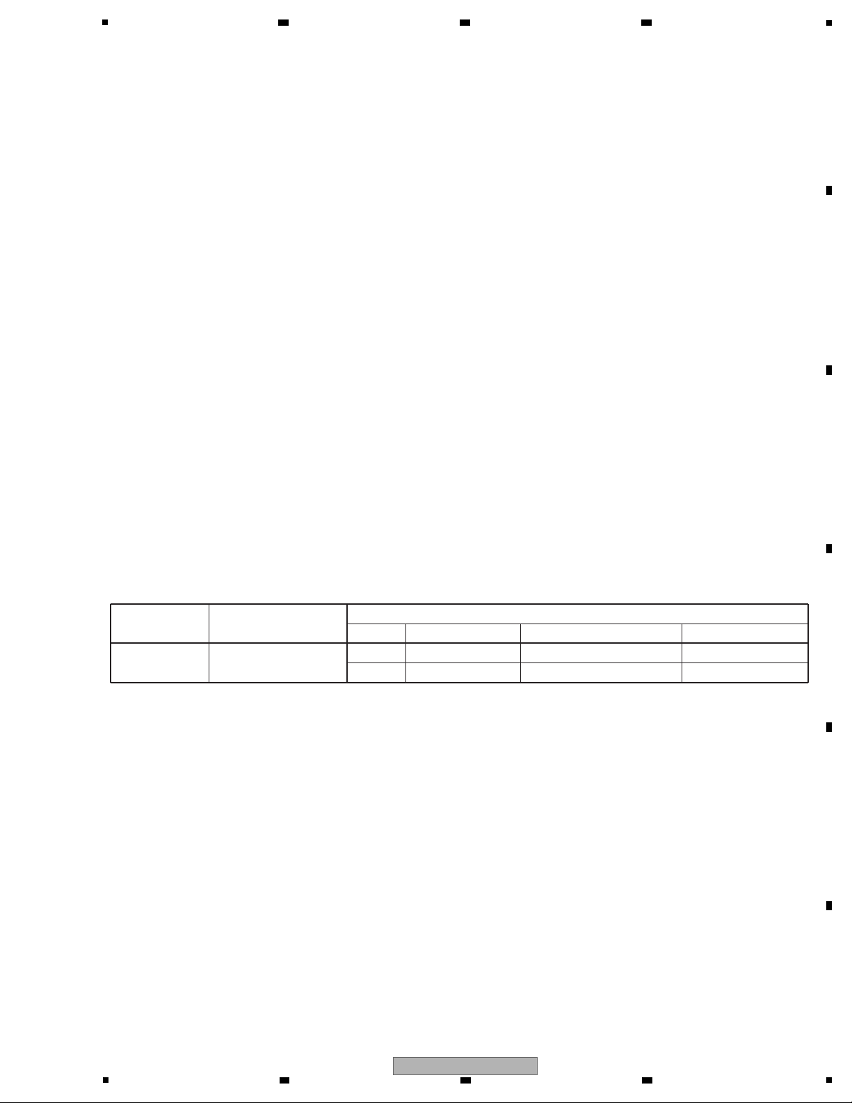
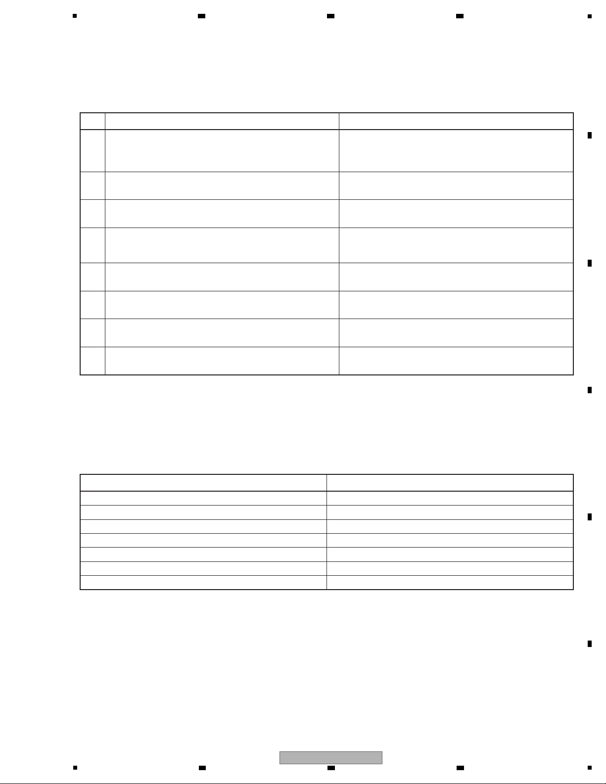
Item to be checked regarding video Item to be checked regarding audio
Block noise Distortion
Horizontal noise Noise
Flicker Volume too low
Disturbed image (video jumpiness) Volume too high
Too dark Volume fluctuating
Too bright Sound interrupted
Mottled color
No. Procedures Check points
1
2
3
4
5
6
7
8
Confirm whether the customer complain has been solved.
If the customer complain occurs with the particular source,
such as Dolby Digital, DTS, AAC, DVD-A and HDMI, input it for
the operation check.
The customer complain must not be reappeared.
Video, Audio and operations must be normal.
Check the analog audio playback.
(Make the analog connections with a DVD player.)
Each channel audio and operations must be normal.
Check the digital audio playback.
(Make the digital connections with a DVD player.)
Each channel audio and operations must be normal.
Check surround playback.
(Select Surround mode and check the multichannel operations
via the DSP circuit.)
Each channel audio and operations must be normal.
Check the tuner (AM and FM) operations. Audio and operations must be normal.
Check the video outputs.
(Connect with a DVD player.)
Video and operations must be normal.
Check the sound from headphone output. Sound must be normal, without noise.
Check the appearance of the product. No scratches or dirt on its appearance after receiving it for
service.
Items to be checked after servicing / VSX, SC
To keep the product quality after servicing, confirm recommended check points shown below.
See the table below for the items to be checked regarding video and audio.
6 7 8
3. BASIC ITEMS FOR SERVICE
3.1 CHECK POINTS AFTER SERVICING
A
B
C
D
E
F
VSX-1020-K
5
6 7 8
11
1
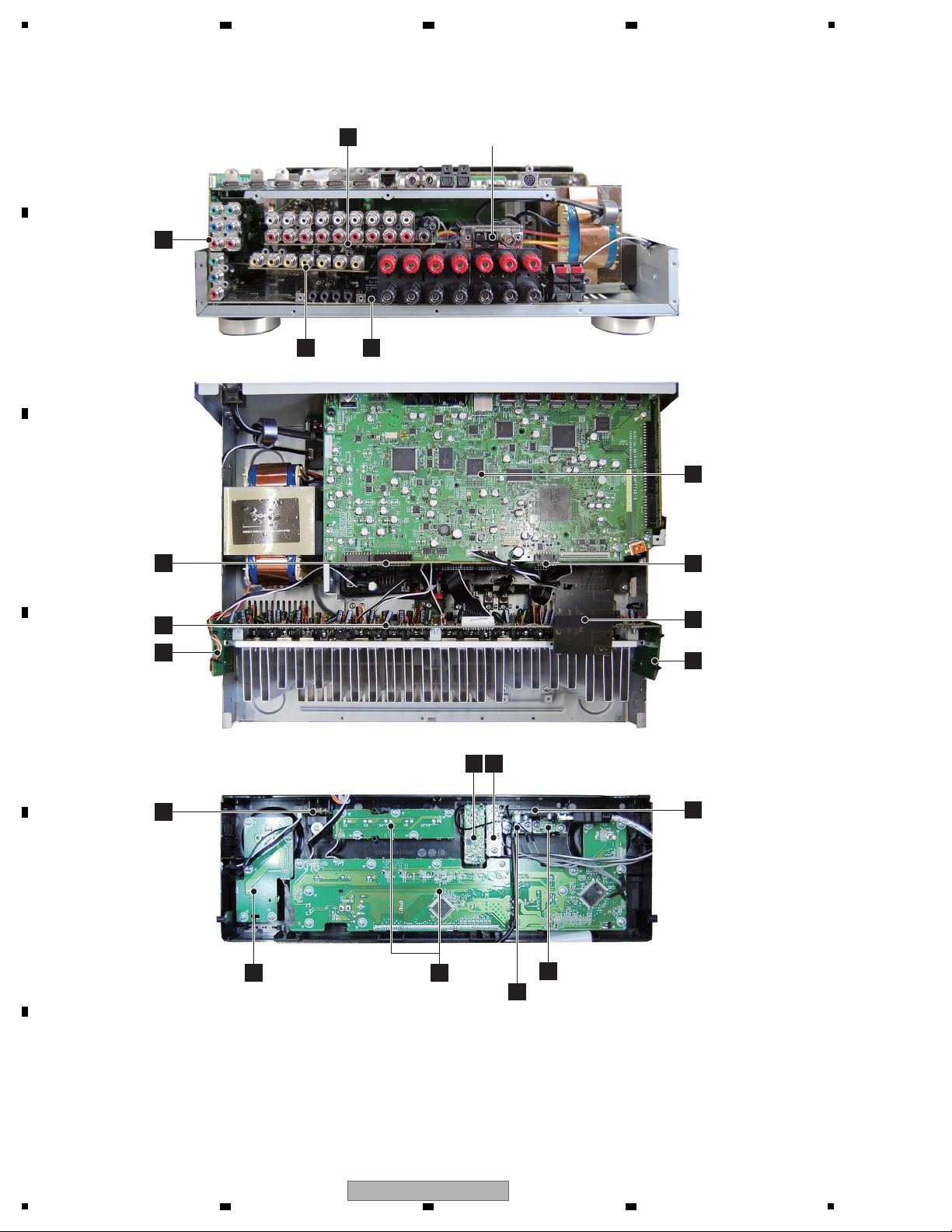
MAIN ASSY
O
DISPLAY ASSY
K
USB MTG ASSY
H
HDMI MTG ASSY
I
POWER SW ASSY
M
COMPOSITE ASSY
C
N
D-MAIN ASSY
P
BRIDGE1 ASSY
G
F-HDMI ASSY
Q
GUIDE3 ASSY
S
GUIDE-R ASSY
B
COMPONENT
ASSY
J
AMP ASSY
F
BRIDGE2 ASSY
L
HEADPHONE
ASSY
R
GUIDE-L ASSY
AUDIO ASSY
A
MIC ASSY F-VIDEO ASSY
D E
FM/AM TUNER UNIT
3.2 PCB LOCATIONS
A
2 3 4
B
C
D
E
F
12
VSX-1020-K
1
2 3 4
5
NSP 1..MAIN ASSY 7025HK0918010-IL
2..MAIN ASSY 7028069211010-IL
2..BRIDGE1 ASSY 7028069213010-IL
2..GUIDE-L ASSY 7028069214010-IL
2..GUIDE-R ASSY 7028069215010-IL
2..GUIDE3 ASSY 7028069218010-IL
NSP 1..FRONT ASSY (VSX-1020-K) 7025HK0918011-IL
NSP 1..FRONT ASSY (VSX-1025-K) 7025HK0918051-IL
2..DISPLAY ASSY (VSX-1020-K) 7028069221010-IL
2..DISPLAY ASSY (VSX-1025-K) 70280692210C0-IL
2..POWER SW ASSY 7028069222010-IL
2..USB MTG ASSY 7028069223010-IL
2..HDMI MTG ASSY 7028069224010-IL
2..HEADPHONE ASSY 7028069225010-IL
NSP 1..AMP ASSY 7025HK0918012-IL
2..AMP ASSY 7028069531010-IL
NSP 1..INPUT ASSY 7025HK0918013-IL
2..AUDIO ASSY 7028069241010-IL
2..COMPONENT ASSY 7028069242010-IL
2..COMPOSITE ASSY 7028069243010-IL
2..BRIDGE2 ASSY 7028069244010-IL
2..F-VIDEO ASSY 7028069245010-IL
2..MIC ASSY 7028069246010-IL
NSP 1..F-HDMI ASSY 7025HK0918014-IL
2..F-HDMI ASSY 7028069251010-IL
NSP 1..D-MAIN ASSY 7025HK0918015-IL
2..D-MAIN ASSY 7028069261010-IL
Mark No. Description Part No. Mark No. Description Part No.
LIST OF ASSEMBLIES
NOTES: - Parts marked by “NSP” are generally unavailable because they are not in our Master Spare Parts List.
-
The > mark found on some component parts indicates the importance of the safety factor of the part.
Therefore, when replacing, be sure to use parts of identical designation.
Jigs List
Jig Name Part No. Remarks
7P extension jig cable GGD1671 Diagnosis (AMP Assy ↔ MAIN Assy)
2P short connector jig GGD1672 Diagnosis (Posistor ↔ MAIN Assy)
13P extension jig cable GGD1669 Diagnosis (AMP Assy ↔ AUDIO Assy)
8P extension jig cable GGD1670 Diagnosis (AMP Assy ↔ MAIN Assy)
Board to board extension jig cable GGD1675 Diagnosis (COMPONENT Assy ↔ MAIN Assy)
Lubricants and Glues List
Name Part No. Remarks
Silicon grease GEM1057 Refer to “9.2 EXTERIOR SECTION”.
Silicon adhesive GYA1011 (KE40RTV-W) Refer to “9.2 EXTERIOR SECTION”.
6 7 8
A
B
3.3 JIGS LIST
C
D
E
VSX-1020-K
5
6 7 8
F
13
1
J
AMP
(702
O
MAIN ASSY
(7028069211010-
K
DISPLAY ASSY
(7028069221010-IL: VSX-1020-K)
(70280692210C0-IL: VSX-1025-K)
G
F-HD
(702
L
HEADPHONE ASSY
(7028069225010-IL)
Q
GUIDE3 ASSY
(7028069218010-IL)
M
POWER SW ASSY
(7028069222010-IL)
H
USB MTG ASSY
(7028069223010-IL)
I
H
(
POWER TRANS
FM/AM
TUNER UNIT
R
GUIDE-L ASSY
(7028069214010-IL)
S
GUIDE-R ASSY
(7028069215010-IL)
-
When ordering service parts, be sure to refer to "EXPLODED VIEWS and PARTS LIST" or "PCB PARTS LIST".
-
The > mark found on some component parts indicates the importance of the safety factor of the part.
Therefore, when replacing, be sure to use parts of identical designation.
-
: The power supply is shown with the marked box.
2 3 4
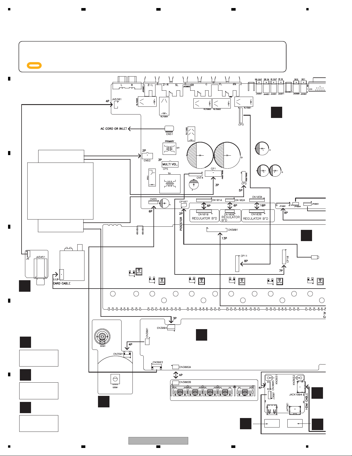
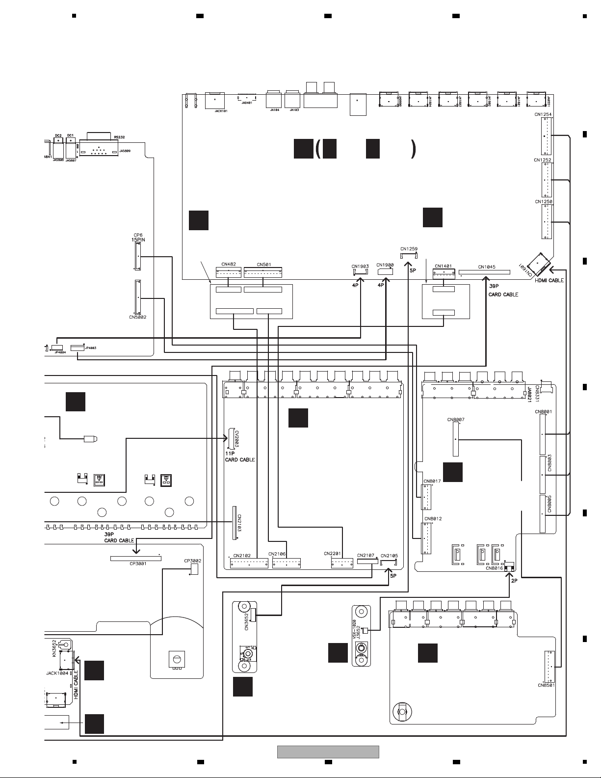
4. BLOCK DIAGRAM
4.1 OVERALL WIRING DIAGRAM
A
B
C
D
E
F
14
1
2 3 4
VSX-1020-K
5
A
AUDIO ASSY
(7028069241010-IL)
J
AMP ASSY
(7028069531010-IL)
ASSY
B
COMPONENT ASSY
(7028069242010-IL)
D
MIC ASSY
(7028069246010-IL)
F
BRIDGE2 ASSY
(7028069244010-IL)
P
BRIDGE1 ASSY
(7028069213010-IL)
G
F-HDMI ASSY
(7028069251010-IL)
I
HDMI MTG ASSY
(7028069224010-IL)
E
F-VIDEO ASSY
(7028069245010-IL)
C
COMPOSITE ASSY
(7028069243010-IL)
CN7612
CN7601
CN7602
CN7614
CN7615CN7613
D-MAIN ASSY
(7028069261010-IL)
N
N N
1/12- 12/12
A
B
C
A
B
C
6 7 8
A
B
C
D
5
6 7 8
VSX-1020-K
E
F
15
1
N
D-MAIN ASSY
2 3 4
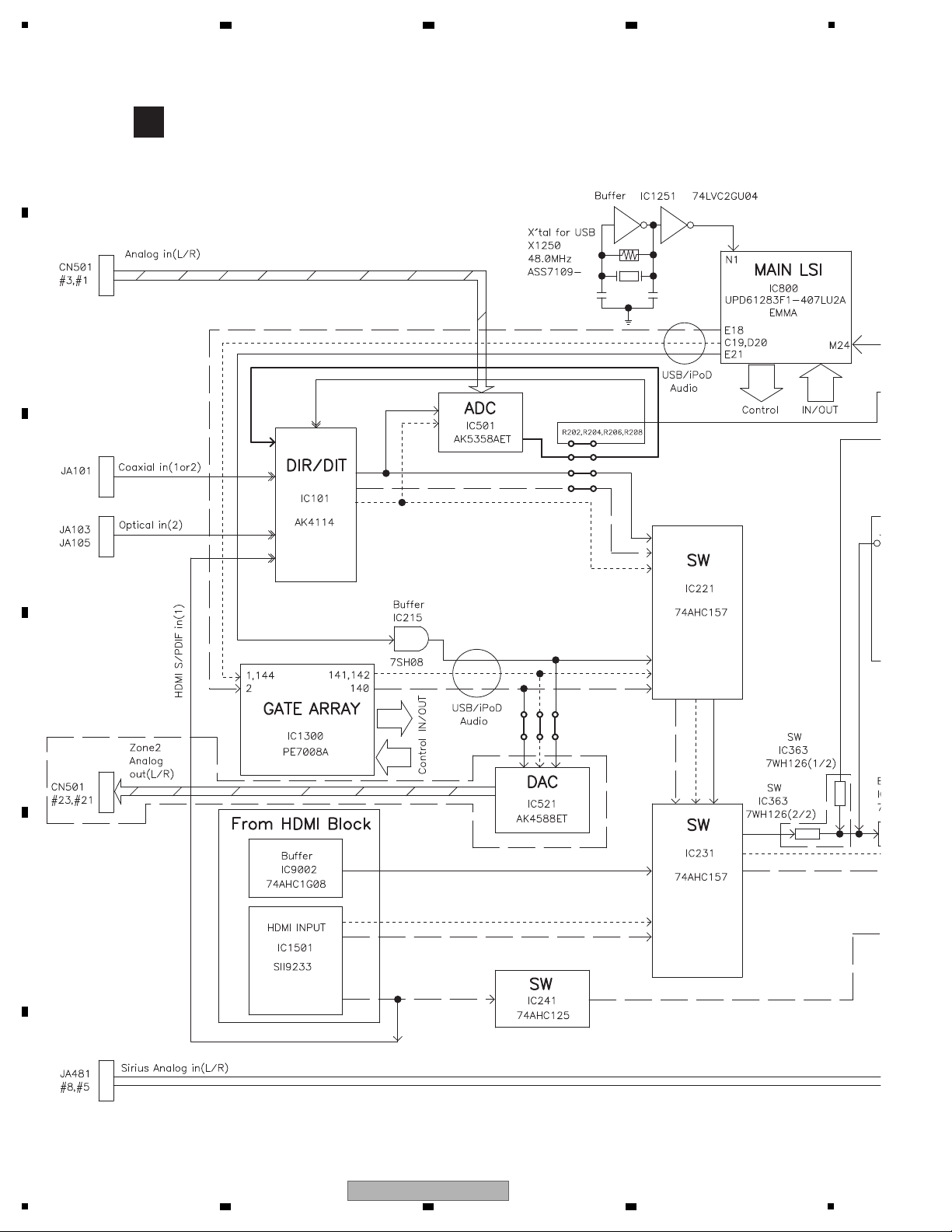
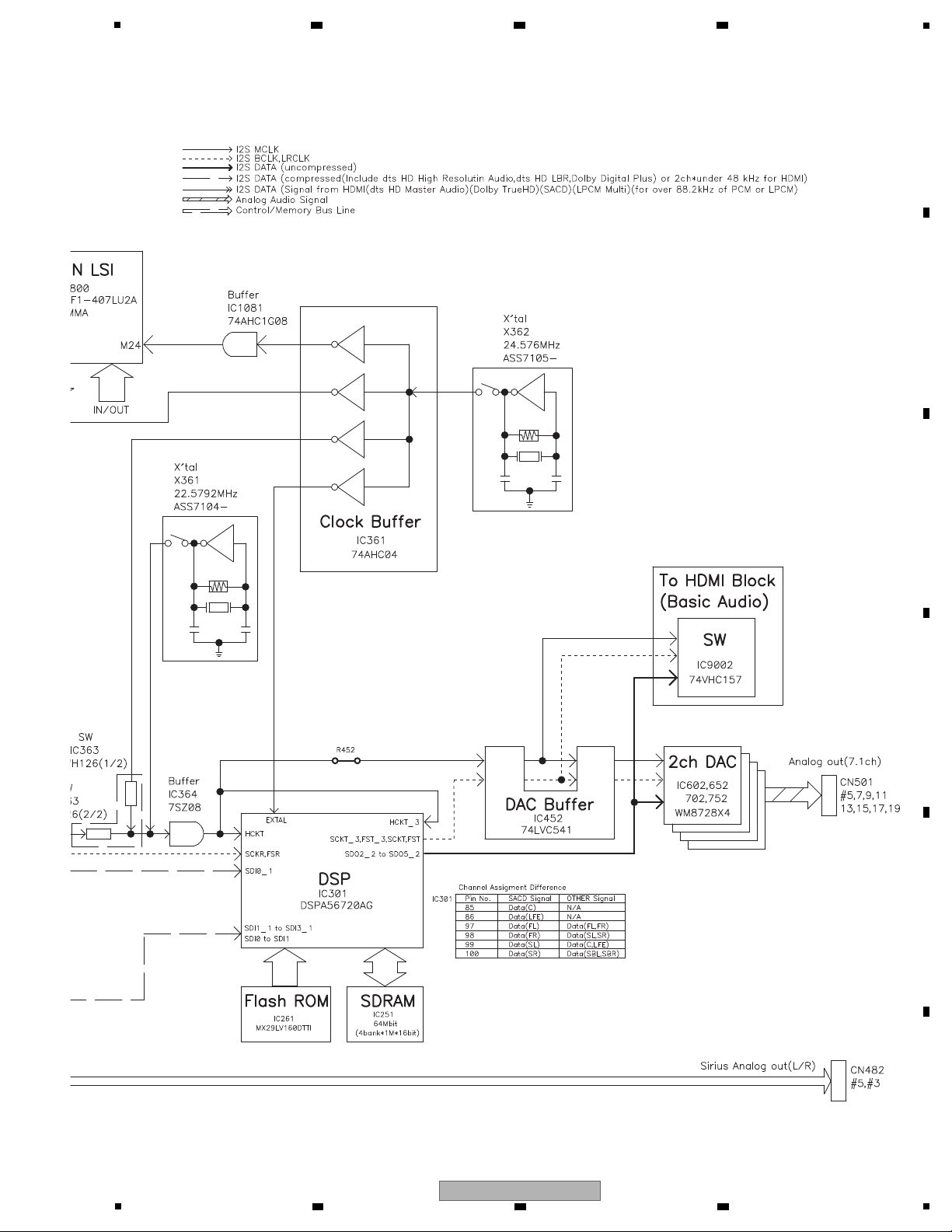
4.2 DIGITAL AUDIO BLOCK DIAGRAM
A
B
C
D
E
F
16
1
2 3 4
VSX-1020-K
5
6 7 8
A
B
C
D
E
F
VSX-1020-K
5
6 7 8
17
1
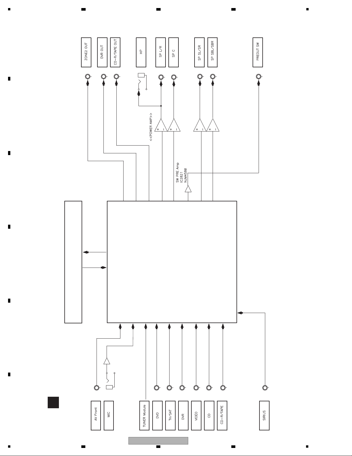
A
AUDIO ASSY
DIGITAL AUDIO BLOCK
Selector / Volume / PRE Amp
IC2501
BD3473KS2
2 3 4
4.3 ANALOG AUDIO BLOCK DIAGRAM
A
B
C
D
E
F
18
1
2 3 4
VSX-1020-K
5
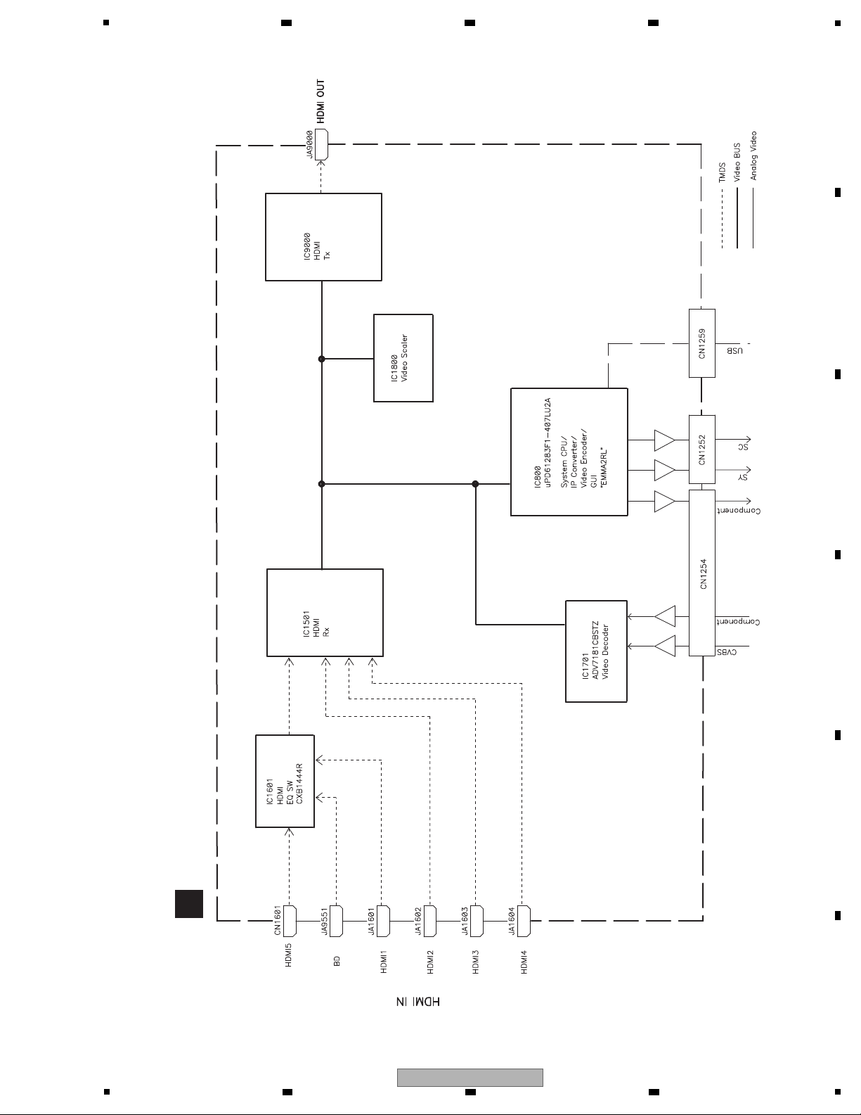
N
D-MAIN ASSY
6 7 8
4.4 DIGITAL VIDEO BLOCK DIAGRAM
A
B
C
D
E
F
VSX-1020-K
5
6 7 8
19
1
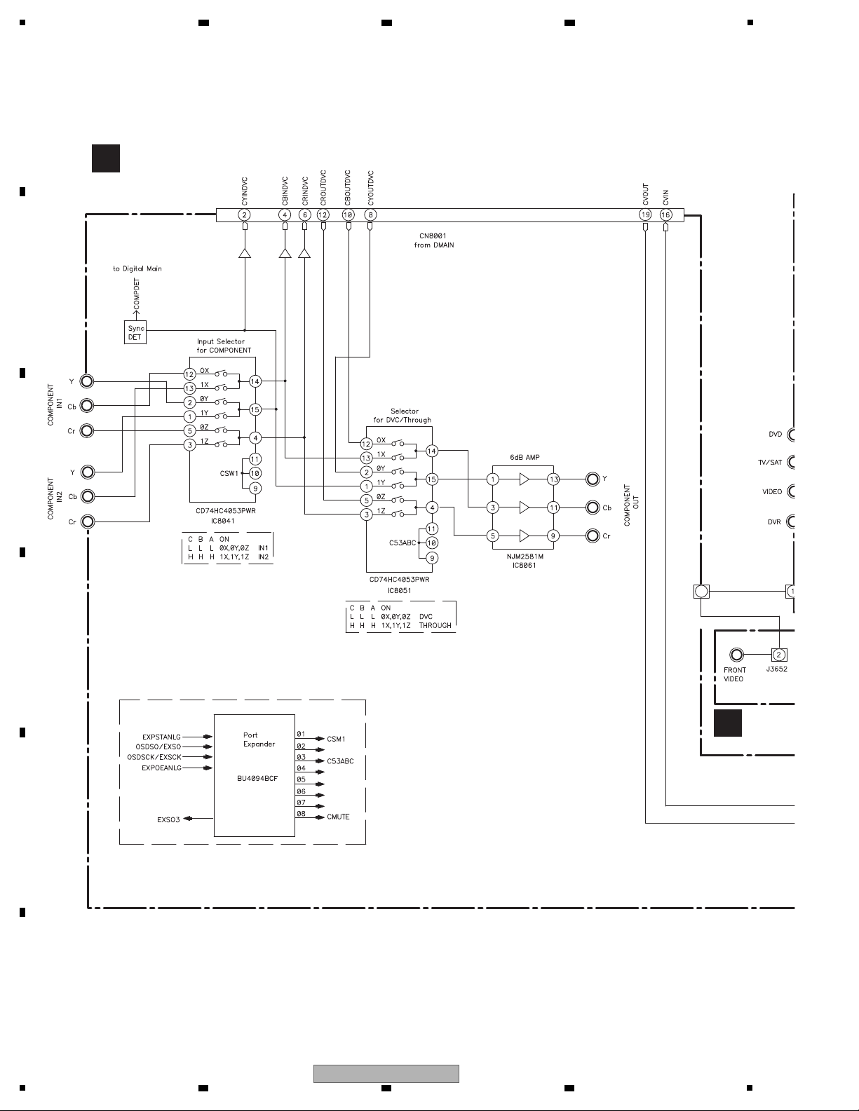
B
COMPONENT ASSY
E
F-VIDE
2 3 4
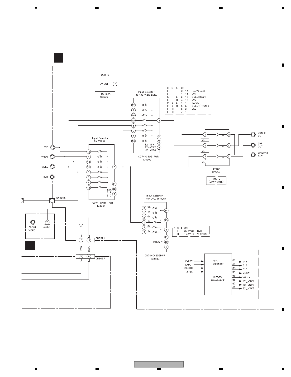
4.5 ANALOG VIDEO BLOCK DIAGRAM
A
B
C
D
E
F
20
1
2 3 4
VSX-1020-K
5
C
COMPOSITE ASSY
E
F-VIDEO ASSY
6 7 8
A
B
C
D
E
F
VSX-1020-K
5
6 7 8
21
1
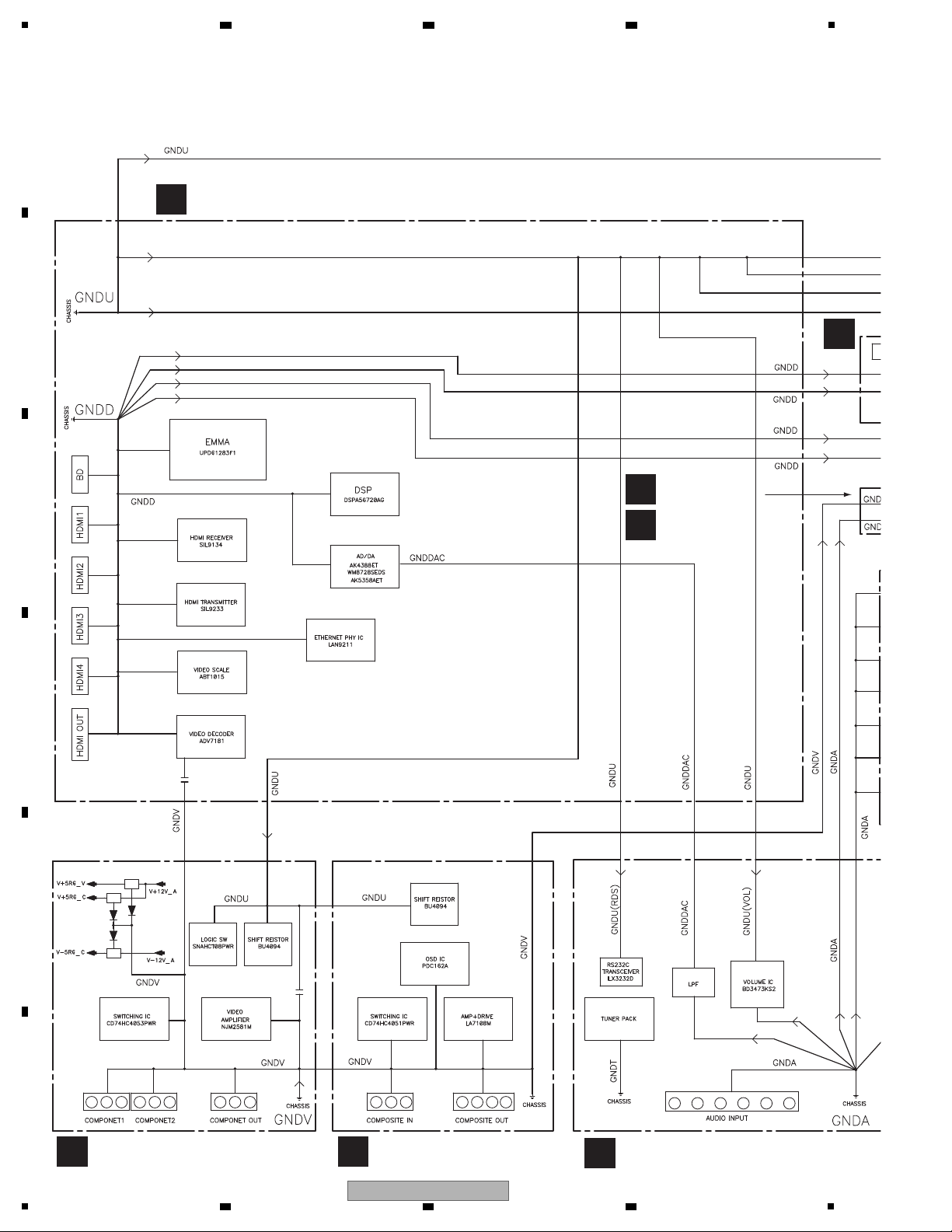
N
D-MAIN ASSY
D
MIC ASSY
E
F-VIDEO
ASSY
B
COMPONENT ASSY
C
COMPOSITE ASSY
A
AUDIO ASSY
G
F-H
4.6 GND BLOCK DIAGRAM
A
B
2 3 4
C
D
E
F
22
1
VSX-1020-K
2 3 4
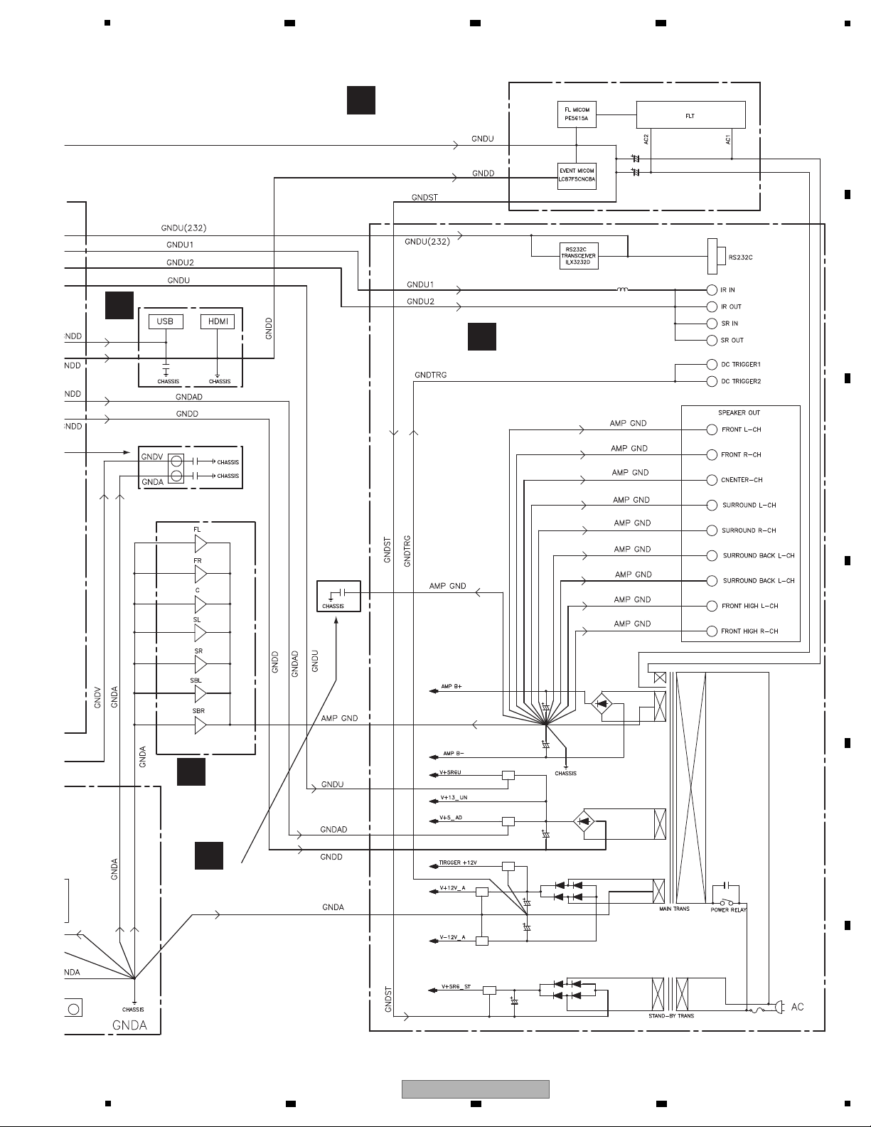
O
MAIN ASSY
J
AMP ASSY
L
HEADPHONE ASSY
G
F-HDMI ASSY
K
DISPLAY ASSY
5
6 7 8
A
B
C
D
E
5
VSX-1020-K
6 7 8
F
23

1
A
B
2 3 4
C
D
E
F
24
1
2 3 4
VSX-1020-K
5
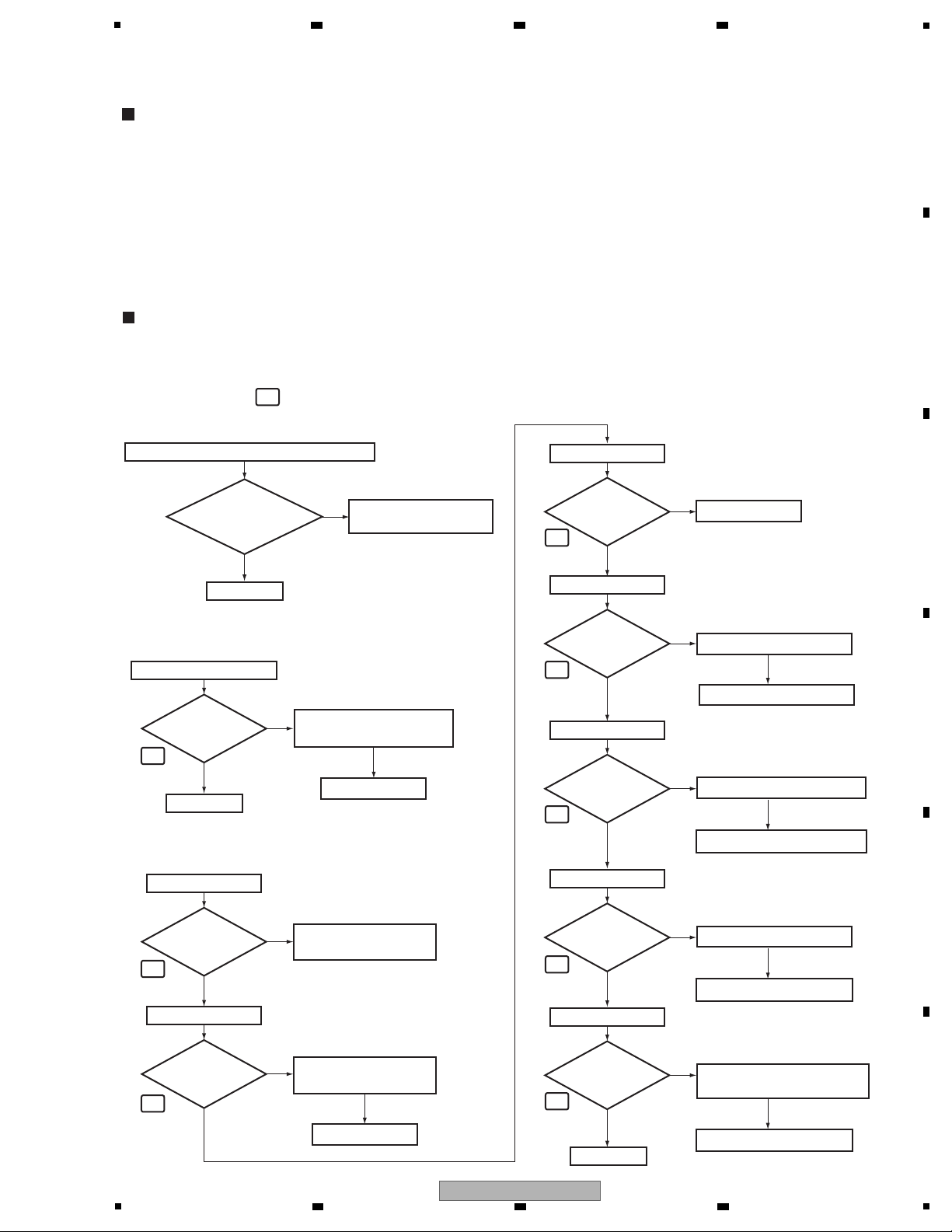
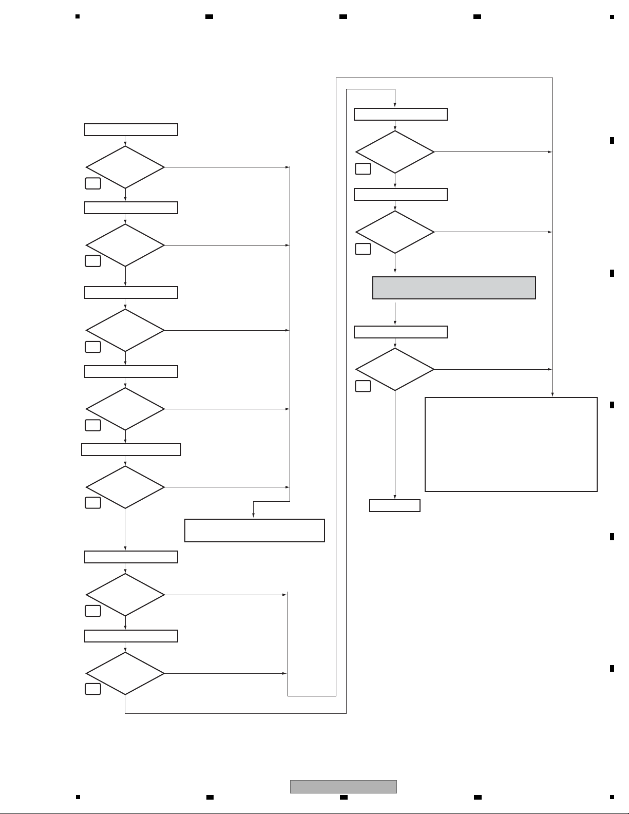
Step 1: MUTE pin
Replace IC301.
Replace D582.
To Step 2
To Step 3
Step 0: Preliminary confirmation
Confirm the following items before checking
Do
screws of
earth terminal (KN481)
securely tighten
?
Tighten screws securely.
Note:
If this section is not fixed,
the GND for DSP module
may lifted from the chassis
and cause instable potential
and lead to product failures.
No
Ye s
To Step 1
IC301 (Pin 84) (or R324)
Is the
voltage of output
signal 0 V
?
No
No
Ye s
Replace IC582 (side B).
NG
Replace IC581.
NG
DSP1MUTE
V+5_DDD1
Check the Q1900 and
its periphery block.
Check the C121, C114,
C509 and C459.
Check the C333.
IC581 (Pin 1)
Is the
voltage of around
5 V input?
Is the
voltage of 3.3 V
output?
No
Ye s
(to chassis)
V+3R3_D
(to chassis)
D582 (Cathode)
Is the
voltage of around
2.7 V output
?
No
Ye s
IC581 (Pin 3)
No
Ye s
Is the
voltage of 1 V
input?
C333 (+ side)
No
Ye s
V+1_DSPF
NG
Check the C506 and C527.
Check the MAIN Assy.
Is the
voltage of 5 V
input?
C506 (+ side)
No
Ye s
V+5_DAC
NG
Check the C606, C656, C706
and C756.
Replace Q551 (side B).
Is the
voltage of 5 V
input?
C606 (+ side)
No
Ye s
V+5_DACA
NG
Check the C552.
Replace R552.
Is the
voltage of around
5 V input?
C552 (+ side)
No
Ye s
V+5_DACD
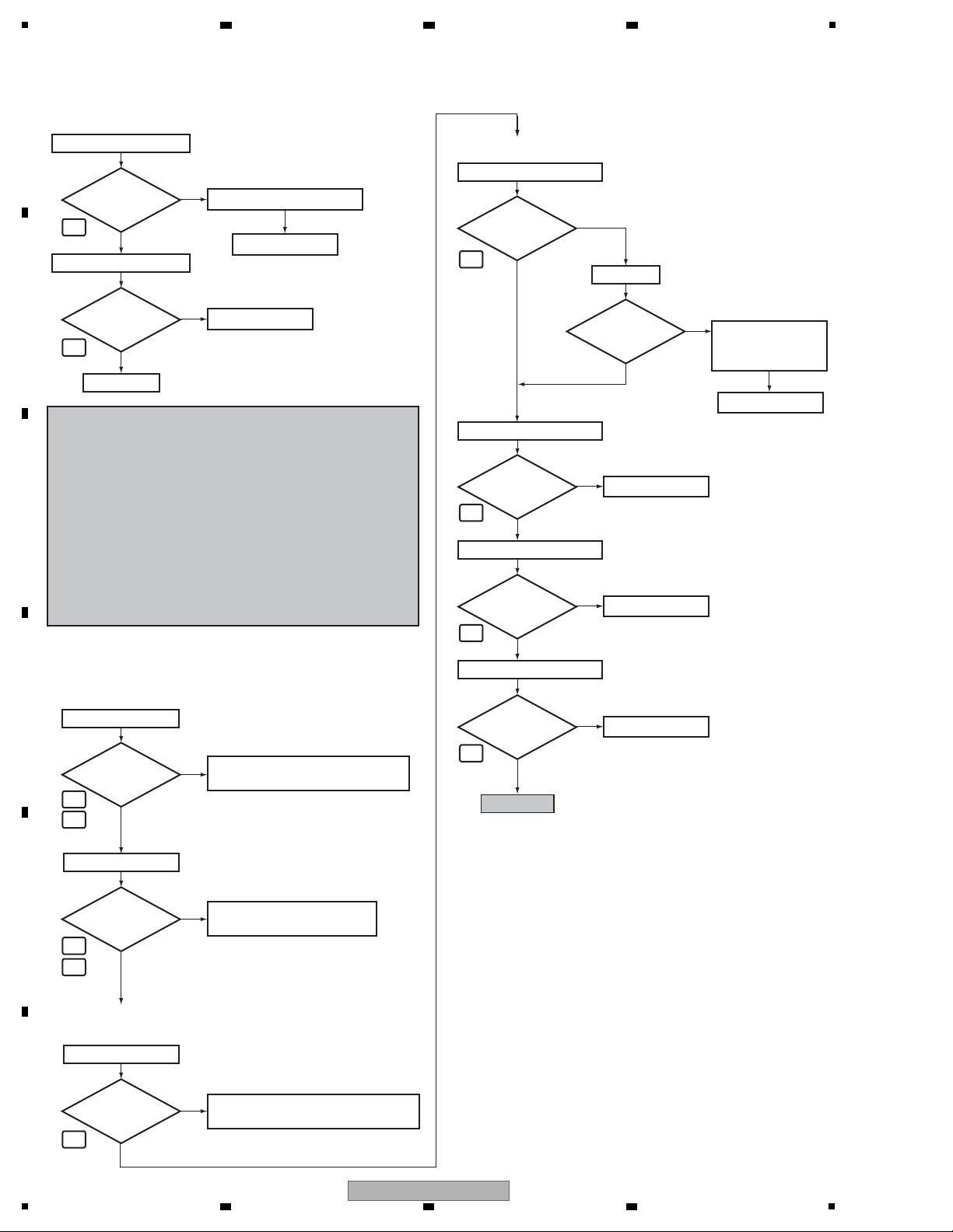
Step 2: Power supply
Simplified diagnosis
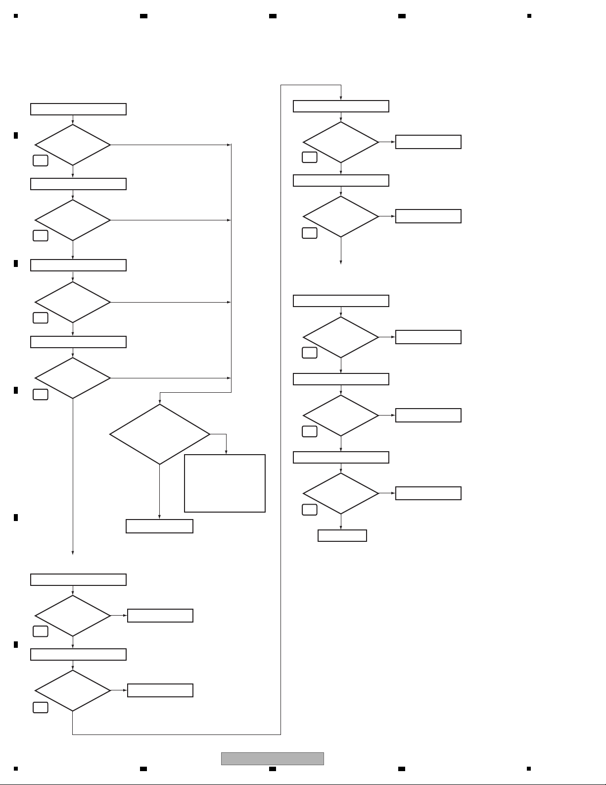
Errors in the Audio Part of the D-MAIN Assy (those simply and roughly predictable by machine operation only)
• Sound abnormality in Delay
If sound abnormality does not occur in the Delay OFF state but occurs in the Delay ON state, it is most likely that a failure
has occurred in SDRAM (IC251) or LATCH (IC281, IC291) in the DSP Part.
• No sound at analog signal input
If sound abnormality does not occur with digital signal input (COAX, OPT, etc.) but occurs only with analog signal input,
it is most likely that a failure has occurred in the AD converter (IC501).
• No sound with the PQLS ON (normal sound with the PQLS OFF)
If no sound is output during CD playback with the PQLS ON, it is most likely that a failure has occurred in the crystal
oscillator (X361). (Diagnosis point A)
<If no sound is output in Multi-Channel-Signal Playback or Surround mode with the COAX, OPT, USB, and HDMI inputs>
• Assume that the LCRs are neither in poor connection nor damaged.
• Assume that diagnosis is performed from Side A.
• This shows failure analysis for the DSP Part of the D-MAIN Assy.
DSP Troubleshooting
Check the DSP and down
stream block. Go to step 6.
1
4
5
6
7
8
2
3
1
• The parts marked like in the following chart are located in "Check Points of the D-MAIN Assy."
6 7 8
5. DIAGNOSIS
5.1 DIAGNOSIS FLOWCHART
A
B
C
D
E
5
VSX-1020-K
6 7 8
F
25
A
Step 4: DIR
Step 4-1
Check the parts and patterns
in the path.
Check the HDMI part, and the parts
and patterns in the path.
Check the OPTICAL IN JACK,
and parts and patterns in the path.
Check the path to
the IC1305
(Port expander).
R101, R102
OPT
Check that the S/PDIF signal is output.
Check that changes by pulling out and inserting the digital
input lines.
Can
observe the
digital signal
?
No
(0 V ⇔ 4 V)
Ye s
R122, R123
COAX
Can
observe the
digital signal
?
No
Ye s
Ye s
Check that it changes in the Playback and Pause modes of
the HDMI.
(0 V ⇔ 3.3 V)
IC101 (Pin 5)
From HDMI part
Can
observe the
digital signal
?
No
(1.65 V center, amplitude more than 0.2 Vp-p)
Step 3: X'tal
To Step 4
Check the X362 (side B).
Replace IC361.
Replace IC361.
Ye s
IC361 (Pins 1, 3, 5, 13)
IC361 (Pins 2, 4, 6, 12)
No
NG
Is there
a 24.576 MHz
input?
No
Is there
a 24.576 MHz
output?
Ye s
Replace IC101.
Ye s
No
Is there
a bit clock
output?
(0 V ⇔ 3.3 V)
To Step 5-3
Replace IC101.
(0 V ⇔ 3.3 V)
Ye s
No
Is there
a LR clock
output?
Replace IC101.
Ye s
R117
XDIRRST
No
NG
Is the
input signal
3.3 V?
Replace IC101.
(0 V ⇔ 3.3 V)
Ye s
No
Is there a
data output?
(0 V ⇔ 3.3 V)
IC101 (Pin 23) (or R110)
DIRMCLK (Master clock)
IC101 (Pin 24) (or R111)
DIRLRCK (LR clock)
IC101 (Pin 25) (or R112)
DIRADAT (Data)
IC101 (Pin 26) (or R113)
DIRBCK (Bit clock)
No
Ye s
Is there a
master clock
output?
Check that the data and clock signals are output.
• When the COAX or OPT is input, go to Step 4.
• When the HDMI (SPDIF path) is input, go to Step 4-1.
Used Source:
[dts HD High Resolution Audio], [dts HD LBR],
[Dolby Digital Plus], [2ch of 48kHz sampling rate or less],
[Other compression stream]
• When the HDMI (SACD) is input, go to Step 5-1.
Used Source: [SACD]
• When the HDMI (I2S path) is input, go to Step 5-2.
Used Source:
[dts HD Master Audio], [Dolby True HD],
[PCM or LPCM of 88.2kHz sampling rate or more],
[LPCM Multi ch]
• When the USB is input, go to Step 5-3.
9
9
10
11
13
14
15
16
17
18
19
B
1
2 3 4
C
D
E
F
26
1
VSX-1020-K
2 3 4
5
To Step 6
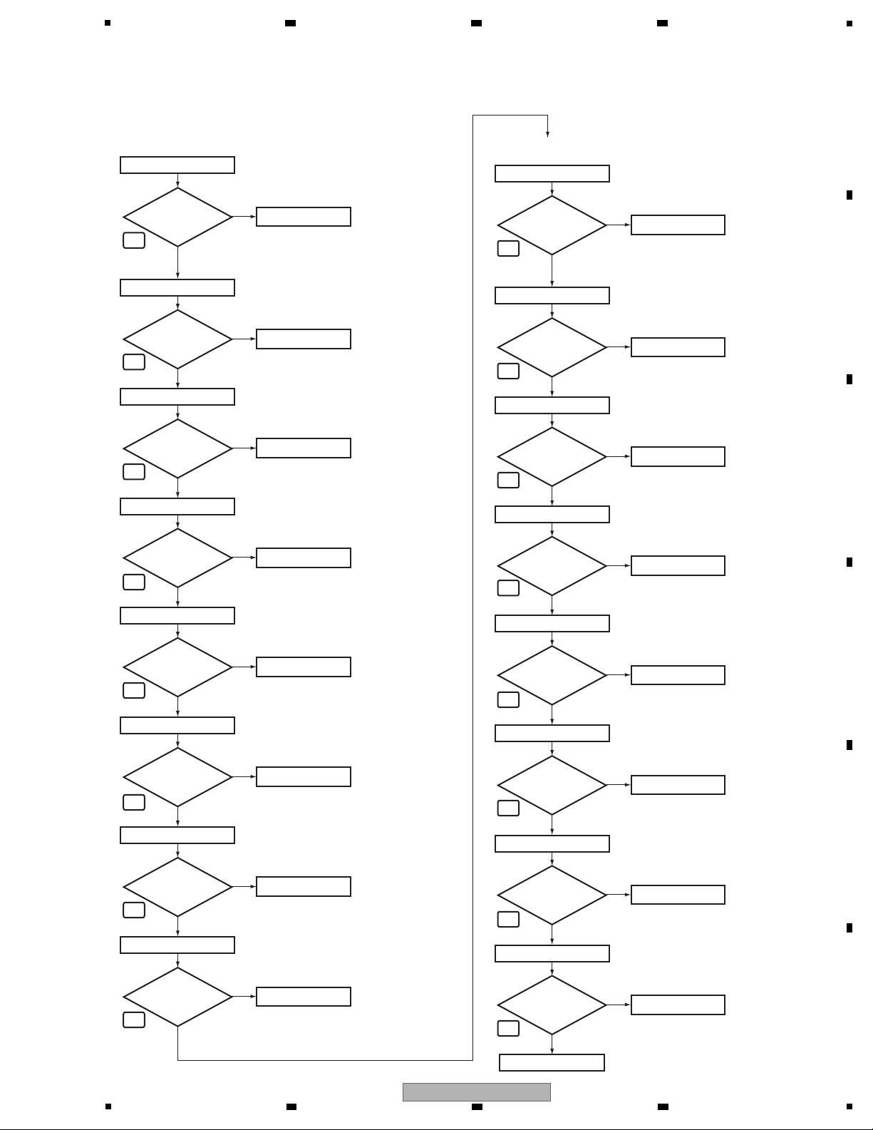
Step 5: DSP input (digital)
Step 5-1
Step 5-3
Step 5-2
Step 5-4
Digital input of each CH when inputting the digital
signal with audio.
Ye s
IC301 (Pin 86) (or R326)
IC301 (Pin 85) (or R325)
IC301 (Pin 98) (or R332)
IC301 (Pin 99) (or R332)
LFE data (SACD)
No
Is there
a data input?
Ye s
Center data (SACD)
No
Is there
a data input?
Ye s
Surround L/R data
(Front R data (SACD))
No
Is there
a data input?
(0 V ⇔ 3.3 V)
(0 V ⇔ 3.3 V)
(0 V ⇔ 3.3 V)
Ye s
Center/LFE data
(Surround L data (SACD))
No
Is there
a data input?
(0 V ⇔ 3.3 V)
IC301 (Pin 100) (or R332)
Ye s
Surround Back L/R data
(Surround R data (SACD))
No
Is there
a data input?
(0 V ⇔ 3.3 V)
IC301 (Pin 89) (or R327)
IC301 (Pin 134)
Ye s
DSP0MCLK
No
Is there
a data input?
(0 V ⇔ 3.3 V)
Ye s
DSP1MCLK
No
Is there
a data input?
(0 V ⇔ 3.3 V)
IC301 (Pin 93) (or R330)
Ye s
S3BCK
No
Is there
a data input?
(0 V ⇔ 3.3 V)
IC301 (Pin 97) (or R332)
Ye s
Front L/R data
(Front L data (SACD))
No
Is there
a data input?
(0 V ⇔ 3.3 V)
IC301 (Pin 94) (or R331)
S3LRCK
No
Is there
a data input?
(0 V ⇔ 3.3 V)
Check the HDMI part, and the parts
and patterns in the path.
• When the USB is input, check the IC1300
and IC800, and the parts and patterns in
the path.
• When the HDMI I2S or HDMI SACD is input,
check the HDMI part, and the parts and
patterns in the path.
• When the COAX, OPT or HDMI SPDIF is
input, check the parts and patterns in the
path.
When the source is SACD, go to Step 6.
When the source is others, go to Step 5-4.
20
21
22
22
22
23
24
25
22
26
6 7 8
A
B
C
D
E
F
VSX-1020-K
5
6 7 8
27
1
Step 6: DSP output (digital)
DAC Buffer
Digital output of each CH when inputting the digital
signal with audio.
Ye s
Center/LFE data
No
Is there
a data output?
Ye s
Surround L/R data
No
Is there
a data output?
Ye s
Front L/R data
No
Is there
a data output?
(0 V ⇔ 3.3 V)
(0 V ⇔ 3.3 V)
(0 V ⇔ 3.3 V)
Ye s
Surround Back L/R data
No
Is there
a data output?
(0 V ⇔ 3.3 V)
IC301 (Pin 123) (or R348)
IC301 (Pin 124) (or R348)
IC301 (Pin 125) (or R348)
IC301 (Pin 122) (or R348)
IC301 (Pin 123) (or R348)
IC301 (Pin 124) (or R348)
IC301 (Pin 125) (or R348)
IC301 (Pin 122) (or R348)
IC452 (Pin 16) (or R459)
IC452 (Pin 13) (or R458)
IC452 (Pin 11) (or R458)
Digital output of each CH when inputting the digital signal
(-∞ dB (no audio)).
Replace IC301.
There is a possibility
of the Boot error.
(Identification of the
defective part near
DSP is extremely
difficult.)
No
Ye s
Is the
voltage of
XDSP1RST at 3.3 V?
(Does it drop to 0V
periodically?)
Ye s
Replace IC301.
Surround L/R data
No
Is the output
0 V fixing?
Replace IC301.
Ye s
Center/LFE data
No
Is the output
0 V fixing?
Surround Back L/R data
Ye s
Replace IC301.
Front L/R data
No
Is the output
0 V fixing?
Ye s
Replace IC301.
No
Is the output
0 V fixing?
DA2MCLK (Master clock)
Ye s
Replace IC452.
No
Is there
a master clock
output?
Check that the clock signal is output.
(0 V ⇔ 3.3 V)
DA2BCK (Bit clock)
Ye s
Replace IC452.
No
Is there
a bit clock
output?
(0 V ⇔ 3.3 V)
(0 V ⇔ 3.3 V)
DA2LRCK (LR clock)
Ye s
Replace IC452.
No
Is there
a LR clock
output?
To Step 7
27
27
27
27
27
27
27
27
28
29
29
A
2 3 4
B
C
D
E
F
28
1
VSX-1020-K
2 3 4
5
Replace IC651.
Ye s
CN501 (Pin 9)
Surround R out
No
Replace IC601.
Ye s
CN501 (Pin 7)
Front L out
No
Replace IC601.
Ye s
CN501 (Pin 5)
Front R out
No
Replace IC701.
Ye s
CN501 (Pin 15)
Center out
No
Replace IC701.
Ye s
CN501 (Pin 13)
Sub Woofer out
No
Replace IC751.
Ye s
CN501 (Pin 19)
Surround Back L out
No
Replace IC751.
Ye s
CN501 (Pin 17)
Surround Back R out
No
Replace IC651.
Ye s
CN501 (Pin 11)
Surround L out
No
Analog output of each CH when inputting the digital
signal (-∞ dB (no audio)).
End
Is the output
2.5 V fixing?
Is the output
2.5 V fixing?
Is the output
2.5 V fixing?
Is the output
2.5 V fixing?
Is the output
2.5 V fixing?
Is the output
2.5 V fixing?
Is the output
2.5 V fixing?
Is the output
2.5 V fixing?
Replace IC651.
Ye s
CN501 (Pin 9)
Surround R out
No
Is there
a data output?
Replace IC601.
Ye s
CN501 (Pin 7)
Front L out
No
Is there
a data output?
Replace IC601.
Ye s
CN501 (Pin 5)
Front R out
No
Is there
a data output?
Step 7: DAC output (analog)
Analog output of each CH when inputting the digital signal
with audio.
Replace IC701.
Ye s
CN501 (Pin 15)
Center out
No
Is there
a data output?
Replace IC701.
Ye s
CN501 (Pin 13)
Sub Woofer out
No
Is there
a data output?
Replace IC751.
Ye s
CN501 (Pin 19)
Surround Back L out
No
Is there
a data output?
Replace IC751.
Ye s
CN501 (Pin 17)
Surround Back R out
No
Is there
a data output?
Replace IC651.
Ye s
CN501 (Pin 11)
Surround L out
No
Is there
a data output?
34
34
34
34
34
34
34
34
34
34
34
34
34
34
34
34
6 7 8
A
B
C
D
5
6 7 8
VSX-1020-K
E
F
29
1
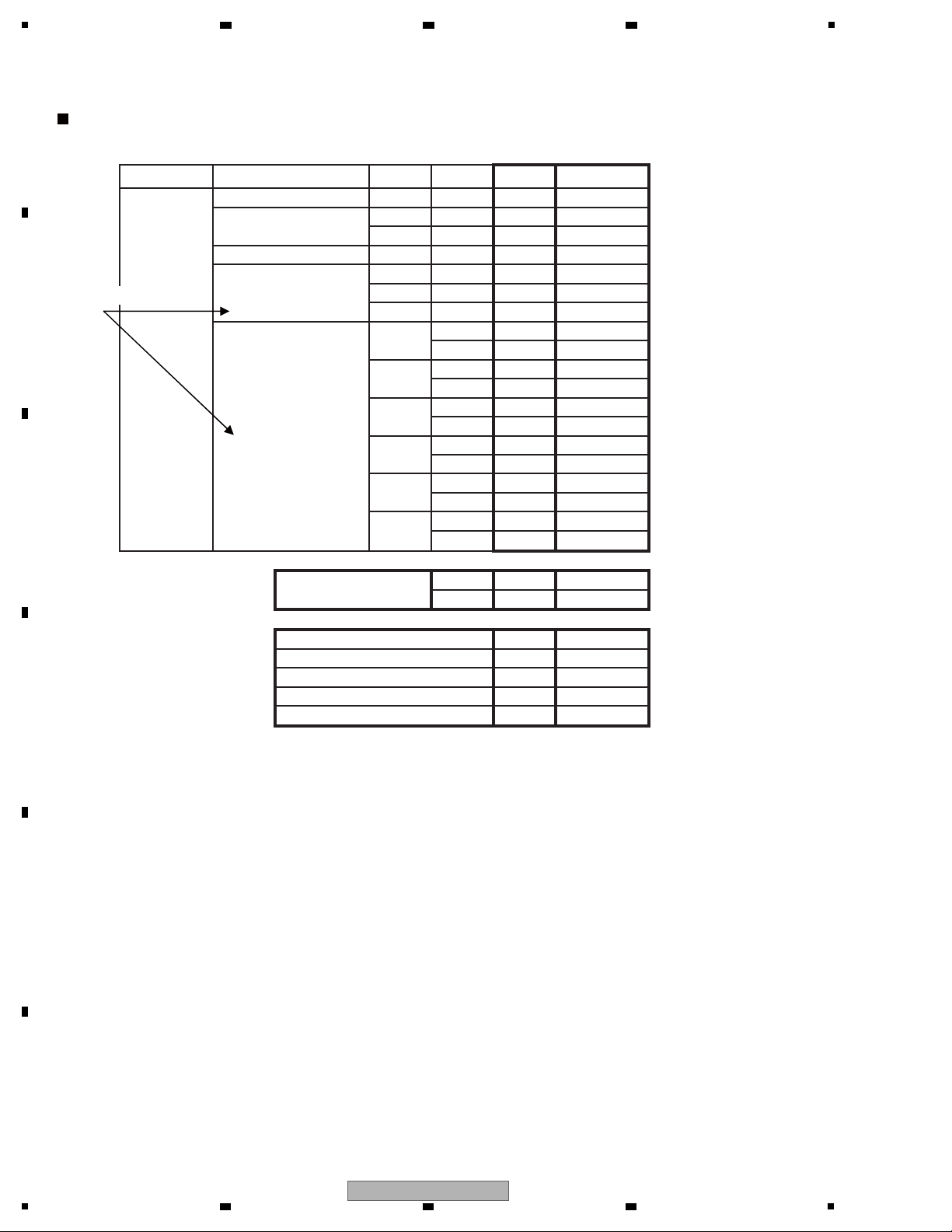
Conditions for selecting SPDIF or I2S output (HDMI transmission)
pcm
fs (kHz) I2S (3 lines)SPDIFLayout
Compression DVD-V 48
Compression *.WAV 44
48
dts-CD 44
PCM 44
48
DVD-V
96 2ch
LPCM 44
Multi
48 2ch
Multi
88 2ch
Multi
DVD-A
96 2ch
Multi
176
Multi
192 2ch No
2ch No
No
No
No
No
No
2ch No
2ch No
2ch No
2ch No
2ch No
2ch No
No
No
Yes
Yes
Yes
Yes
Yes
Yes
Yes
Yes
Yes
Yes
Yes
Yes
Yes
Yes
Yes
Yes
Yes
Yes
Yes
Yes
Yes
Yes
Yes
Yes
Yes
Yes
2ch
Multi NA NA
NA NA
SACD
2ch (DSD)
Multi
No
No (DSD)
dts HD Master Audio
dts HD High Resolution Audio No
dts HD LBR No
Dolby TrueHD
No
No
Dolby Digital Plus No
Indistinguishable
A
2 3 4
B
C
D
E
F
30
VSX-1020-K
1
2 3 4
Loading...