


Installation Manual
SPH-DA210
SPH-DA110
AppRadio
Connecting the system
Precautions before |
|
• Do not route wires where they will be |
|
||
connecting the system |
|
exposed to high temperatures. If the |
|
||
|
insulation heats up, wires may become |
|
|||
|
|
|
|||
WARNING |
|
damaged, resulting in a short circuit or |
|
||
|
malfunction and permanent damage to |
|
|||
|
|
|
|||
Do not take any steps to tamper with or |
|
the product. |
|
||
disable the parking brake interlock sys- |
|
• Do not cut the GPS antenna cable to |
|
||
tem which is in place for your protec- |
|
shorten it or use an extension to make |
|
||
tion. Tampering with or disabling the |
|
it longer. Altering the antenna cable |
|
||
parking brake interlock system could |
|
could result in a short circuit or mal- |
|
||
result in serious injury or death. |
|
function. |
|
||
CAUTION |
|
• Do not shorten any leads. If you do, the |
|
||
|
protection circuit (fuse holder, fuse |
|
|||
• If you decide to perform the installa |
- |
resistor or filter, etc.) may fail to work |
|
||
tion yourself, and have special training |
|
properly. |
|
||
and experience in the mobile electron- |
|
• Never feed power to other electronic |
|
||
ics installations, please carefully fol |
|
- |
|
|
|
low all of the steps in the installation |
|
products by cutting the insulation of |
|
||
|
the power supply lead of this product |
|
|||
manual. |
|
and tapping into the lead. The current |
|
||
• Secure all wiring with cable clamps or |
|
capacity of the lead will be exceeded, |
|
||
electrical tape. Do not allow any bare |
|
causing overheating. |
|
||
wiring to remain exposed. |
|
|
|
|
|
• Do not directly connect the yellow lead |
|
|
|
|
|
of this product to the vehicle battery. If |
|
Before installing this product |
|
||
the lead is directly connected to the |
|
• Use this unit with a 12-volt battery and |
|
||
battery, engine vibration may eventu- |
|
|
|||
|
negative grounding only. Failure to do so |
|
|||
ally cause the insulation to fail at the |
|
|
|||
|
may result in a fire or malfunction. |
|
|||
point where the wire passes from the |
|
|
|||
|
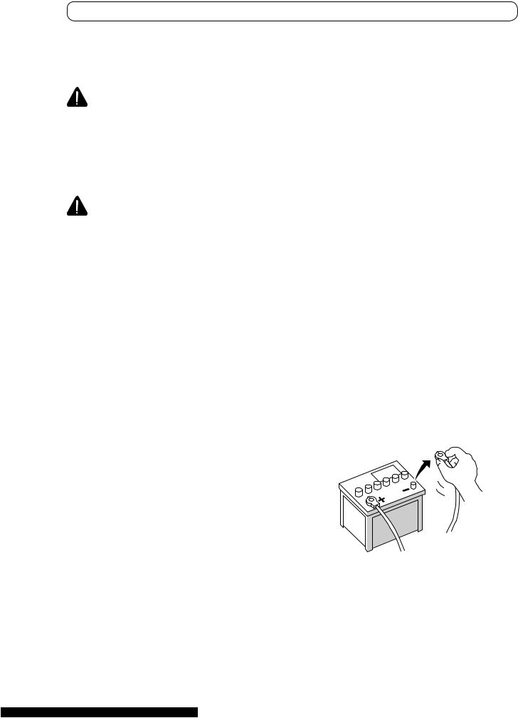
To avoid shorts in the electrical system, be |
|
|||
passenger compartment into the |
|
|
|||
|
sure to disconnect the (−) battery cable be |
- |
|||
engine compartment. If the yellow |
|
||||
|
fore installation. |
|
|||
lead’s insulation tears as a result of |
|
|
|||
|
|
|
|
|
|
contact with metal parts, short-circuit |
|
- |
|
|
|
ing can occur, resulting in considerable |
|
|
|
|
|
danger. |
|
|
|
|
|
• It is extremely dangerous to allow |
|
|
|
|
|
|
|
|
|
|
|
cables to become wound around the |
|
|
|
|
|
|
|
|
|
|
|
steering column or shift lever. Be sure |
|
|
|
|
|
|
|
|
|
|
|
to install this product, its cables, and |
|
|
|
|
|
wiring away in such so that they will |
|
|
|
|
|
|
|
|
|
|
|
not obstruct or hinder driving. |
|
|
|
|
|
•Make sure that the cables and wires will not interfere with or become caught in any of the vehicle’s moving parts, especially the steering wheel, shift lever, parking brake, sliding seat tracks, doors, or any of the vehicle’s controls.
Connecting the system
To prevent damage
 WARNING
•Use speakers over 50 W (output value) and between 4 Ω to 8 Ω (impedance value). Do not use 1 Ω to 3 Ω speakers for this unit.
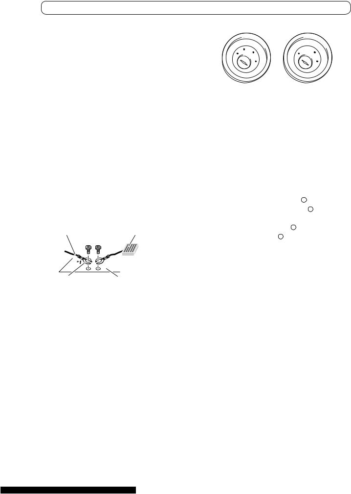
•The black cable is ground. When installing this unit or power amp (sold separately), make sure to connect the ground wire first. Ensure that the ground wire is properly connected to metal parts of the car’s body. The ground wire of the power amp and the one of this unit or any other device must be connected to the car sepa rately with different screws. If the screw for the ground wire loosens or falls out, it could result in fire genera tion of smoke or malfunction.
Ground wire |
Power amp |
Other devices Metal parts of car’s body (Another electronic
device in the car)
*1 Not supplied for this unit.
•When replacing the fuse, be sure to only use a fuse of the rating prescribed on this product.
•When disconnecting a connector, pull the connector itself. Do not pull the lead, as you may pull it out of the con nector.
•This product cannot be installed in a vehicle without ACC (accessory) posi tion on the ignition switch.
|
|
CC |
|
|
|
|
|
|
|
|
|
|
|
|
|
F |
A |
O |
|
|
F |
|
|
O |
|
|
|||
|
|
N |
|
|
|
|
N |
|
||||||
O |
F |
|
|
|
|
O |
F |
|
|
|
|
|
||
|
|
S |
|
|
|
|
|
|
S |
|
||||
|
|
|
|
|
|
|
|
|
|
|
||||
|
|
|
T |
|
|
|
|
|
|
|
|
T |
|
|
|
|
|
A |
|
|
|
|
|
|
|
R |
A |
|
|
|
|
|
R |
|
|
|
|
|
|
|
|
|
||
|
|
|
T |
|
|
|
|
|
|
|
T |
|
|
|
ACC position |
No ACC position |
|
||||||||||||
• To avoid short-circuiting, cover the dis |
- |
|||||||||||||
connected lead with insulating tape. It is |
|
|||||||||||||
especially important to insulate all un |
- |
|||||||||||||
used speaker leads, which if left uncov |
- |
|||||||||||||
ered may cause a short circuit. |
|
|
||||||||||||
• Refer to the owner’s manual for details |
|
|||||||||||||
on connecting the power amp and other |
|
|||||||||||||
-units, then make connections according |
- |
|||||||||||||
ly. |
|
|
|
|
|
|
|
|
|
|
|
|
|
|
• Since a unique BPTL circuit is employed, |
|
|||||||||||||
do -not directly ground the |
|
|
side of the |
|
||||||||||
|
|
|||||||||||||
speaker lead or connect the |
|
|
side of an |
- |
||||||||||
|
|
|||||||||||||
other side of the speaker lead together. |
|
|||||||||||||
Be sure to connect the |
|
side of the |
|
|||||||||||
|
|
|||||||||||||
speaker lead to the |
|
side of the speaker |
|
|||||||||||
|
|
|||||||||||||
lead on this product. |
|
|
|
|
|
|
|
|
|
|
||||
Notice for the blue/white lead
•When the ignition switch is turned on (ACC ON), a control signal is output through the blue/white lead. Connect to an external power amp’s system remote control terminal (max. 300 mA 12 V DC). The control signal is output through the blue/white lead, even if the AV source is switched off.
•Be sure not to use this lead as the power supply lead for the external power amps.
Suchconnection could cause excessive current drain and malfunction.
•Be sure not to use this lead as the power
supply lead for the auto-antenna or an |
- |
- |
|
tenna booster. Such connection could |
|
cause excessive current drain and mal |
- |
function. |
|
Connecting the system
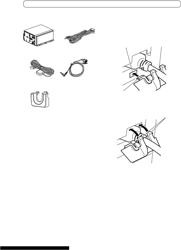
Parts supplied |
Installing the HDMI® cable holder |
|
1 Insert the lower tab of the HDMI ca- |
|
ble holder into the groove of this prod- |
|
uct. |
|
Groove |
This product |
Power cord |
GPS antenna |
Microphone |
|
Tab |
|
2 Insert the two upper tabs into the |
|
|
HDMI cable holder |
this product by pushing the HDMI ca |
- |
|
ble holder. |
Tabs |
|
|
|
|
|
|
pUse the HDMI cable holder when you connect this product with the separately sold HDMI/USB interface cable for iPod / iPhone (CD-IH202) or App Connectivity Kit (CD-AH200).
pNever grip the holder tightly or use force when removing or attaching.
Connecting the system
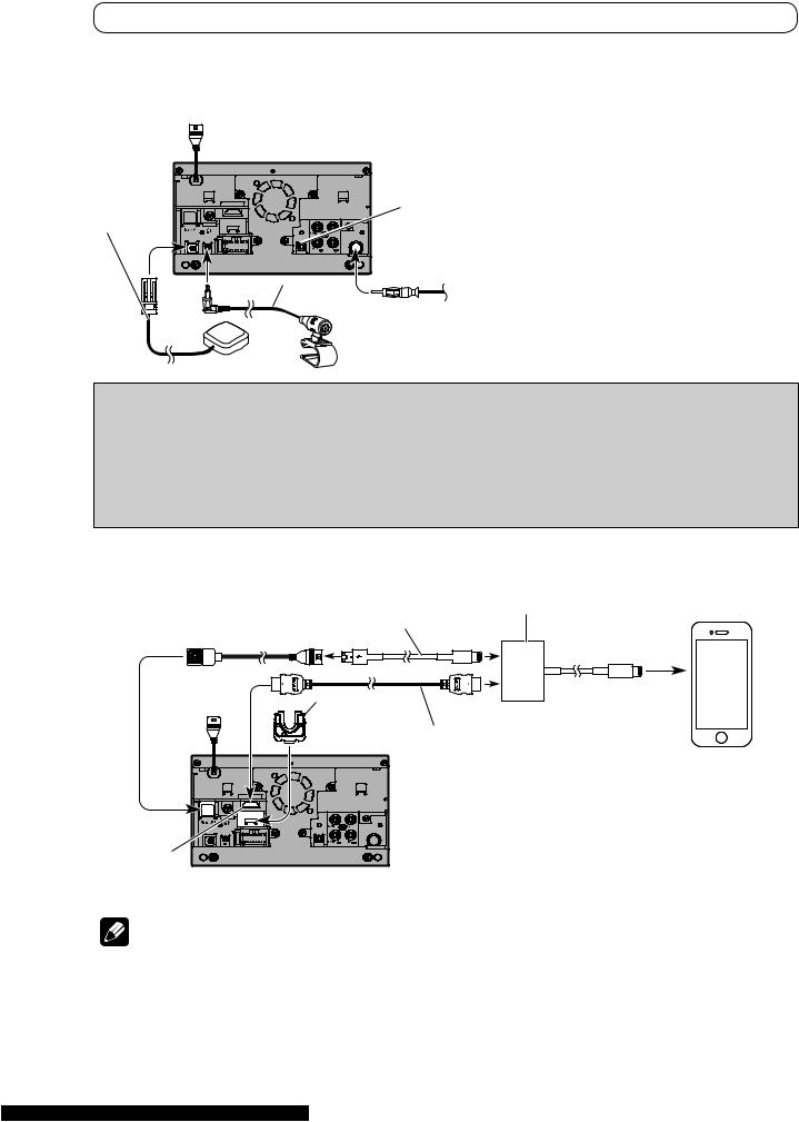
Connecting the system
3.55 m
(1 ft. 2 in.)
This product
4 m
(13 ft. 1 in.)
Wired remote input
Please refer to the instruction manual for the Hard-wired remote control adapter (sold separately).
Vehicle antenna
Microphone
GPS antenna
 WARNING
•To avoid the risk of accident and the potential violation of applicable laws, this product should never be used while the vehicle is being driven except for navigation purposes.
•In some countries, the viewing of images on a display inside a vehicle even by persons other than the driver may be illegal. Where such regulations apply they must be obeyed and this product’s app-based content should not be used.
When connecting an iPhone with Lightning connector
USB cable (*2) (sold separately) 1.5 m (4 ft. 11 in.) 
HDMI port
Lightning Digital AV Adapter Lightning to USB Cable (Apple Inc. products) (sold separately) (CD-IU52) (sold separately)
HDMI cable
holder
High Speed HDMI® Cable (Type A-A) (*2)
(sold separately) 2 m (6 ft. 7 in.) iPhone with Lightning connector (*1)
(*1) For details concerning operations and compatibility, refer to the Operation Manual.
(*2) For details about how to connect the separately sold HDMI/ USB interface cable for iPod / iPhone (CD-IH202), refer to the HDMI/USB interface cable for iPod / iPhone manual.
|
Notes |
|
|
• |
When you connect the High Speed HDMI® Cable, use the HDMI cable holder to fix it securely. |
|
|
• |
The constant connection of the separately sold |
Lightning Digital AV Adapter (Apple |
Inc. |
|
products) is not guaranteed. Disconnect it when it is not used as with a mobile device. |
|
|
|
|
|
|

Connecting the system
When connecting an iPhone with 30-pin
USB interface cable for iPod / iPhone (*4) (sold separately)
 2 m
2 m
(6 ft. 7 in.)
iPhone with 30-pin (*3)
(*3) For details concerning operations and compatibility, refer to the Operation Manual.
(*4) For details about how to connect the separately sold USB interface cable for iPod / iPhone (CD-IU201N), refer to the USB interface cable for iPod / iPhone manual.
When connecting an Android device with an HDMI port
USB cable (*6) (Type USB A - USB A) (sold separately) 0.75 m (2 ft. 6 in.)
USB - micro USB cable (*6) (Type USB A - micro USB B) (sold separately) 1.5 m (4 ft. 11 in.)
USB cable
HDMI port
High Speed HDMI® |
Adapter cable (*6) |
|
|
Cable (*6) (Type A - A) |
|
||
(HDMI Type A - D) |
|
||
(sold separately) |
|
||
(sold separately) |
Android device (*5) |
||
|
|||
HDMI cable holder |
|
||
|
|
(*5) For details concerning operations and compatibility, refer to the Operation Manual.
(*6) For details about how to connect the separately sold App Connectivity Kit (CD-AH200), refer to the App Connectivity Kit manual.
 Notes
Notes
•When you connect the High Speed HDMI® Cable, use the HDMI cable holder to fix it securely.
•An MHL adapter will not be used if you use the adapter cable.
 Loading...