


STEREO CD TUNER
COMBINÉ RADIO/CD
XC-F10
STEREO POWER AMPLIFIER
AMPLIFICATEUR DE PUISSANCE STÉRÉO
M-F10
SPEAKER SYSTEM
ENCEINTES ACOUSTIQUE
S-F10-LRW
Operating Instructions
Mode d’emploi
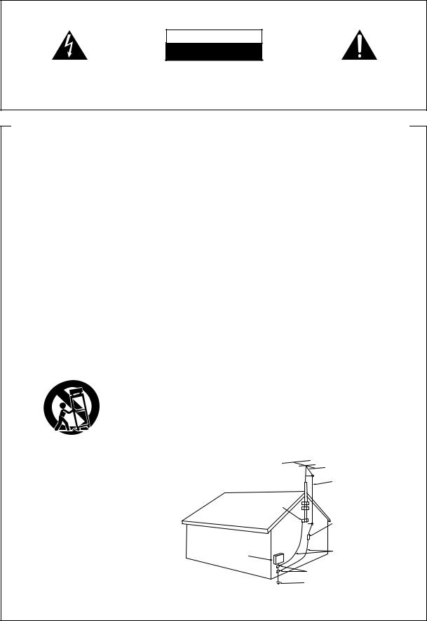
IMPORTANT
CAUTION
RISK OF ELECTRIC SHOCK
DO NOT OPEN
The lightning flash with arrowhead symbol, within an equilateral triangle, is intended to alert the user to the presence of uninsulated "dangerous voltage" within the product's enclosure that may be of sufficient magnitude to constitute a risk of electric shock to persons.
CAUTION:
TO PREVENT THE RISK OF ELECTRIC SHOCK, DO NOT REMOVE COVER (OR BACK). NO USER-SER- VICEABLE PARTS INSIDE. REFER SERVICING TO QUALIFIED SERVICE PERSONNEL.
The exclamation point within an equilateral triangle is intended to alert the user to the presence of important operating and maintenance (servicing) instructions in the literature accompanying the appliance.
IMPORTANT SAFETY INSTRUCTIONS
READ INSTRUCTIONS — All the safety and operating |
GROUNDING OR POLARIZATION |
OBJECT AND LIQUID ENTRY — Never push objects of |
|
instructions should be read before the product is |
¶ If this product is equipped with a polarized alternating |
any kind into this product through openings as they |
|
operated. |
current line plug (a plug having one blade wider than |
may touch dangerous voltage points or short-out |
|
RETAIN INSTRUCTIONS — The safety and operating |
the other), it will fit into the outlet only one way. This |
parts that could result in a fire or electric shock. |
|
instructions should be retained for future reference. |
is a safety feature. If you are unable to insert the plug |
Never spill liquid of any kind on the product. |
|
HEED WARNINGS — All warnings on the product and |
fully into the outlet, try reversing the plug. If the plug |
SERVICING — Do not attempt to service this product |
|
in the operating instructions should be adhered to. |
should still fail to fit, contact your electrician to |
yourself as opening or removing covers may expose |
|
FOLLOW INSTRUCTIONS — All operating and use |
replace your obsolete outlet. Do not defeat the |
you to dangerous voltage or other hazards. Refer all |
|
instructions should be followed. |
safety purpose of the polarized plug. |
servicing to qualified service personnel. |
|
CLEANING — Unplug this product from the wall outlet |
¶ If this product is equipped with a three-wire |
DAMAGE REQUIRING SERVICE — Unplug this product |
|
before cleaning. The product should be cleaned only |
grounding type plug, a plug having a third (grounding) |
from the wall outlet and refer servicing to qualified |
|
with a polishing cloth or a soft dry cloth. Never clean |
pin, it will only fit into a grounding type power outlet. |
service personnel under the following conditions: |
|
with furniture wax, benzine, insecticides or other |
This is a safety feature. If you are unable to insert the |
¶ When the power-supply cord or plug is damaged. |
|
volatile liquids since they may corrode the cabinet. |
plug into the outlet, contact your electrician to |
¶ If liquid has been spilled, or objects have fallen into |
|
ATTACHMENTS — Do not use attachments not |
replace your obsolete outlet. Do not defeat the |
the product. |
|
recommended by the product manufacturer as they |
safety purpose of the grounding type plug. |
¶ If the product has been exposed to rain or water. |
|
may cause hazards. |
POWER-CORD PROTECTION — Power-supply cords |
¶ If the product does not operate normally by following |
|
WATER AND MOISTURE — Do not use this product |
should be routed so that they are not likely to be |
the operating instructions. Adjust only those controls |
|
near water — for example, near a bathtub, wash |
walked on or pinched by items placed upon or |
that are covered by the operating instructions as an |
|
bowl, kitchen sink, or laundry tub; in a wet basement; |
against them, paying particular attention to cords at |
improper adjustment of other controls may result in |
|
or near a swimming pool; and the like. |
plugs, convenience receptacles, and the point where |
damage and will often require extensive work by a |
|
ACCESSORIES — Do not place this product on an |
they exit from the product. |
qualified technician to restore the product to its |
|
unstable cart, stand, tripod, bracket, or table. The |
OUTDOOR ANTENNA GROUNDING — If an outside |
normal operation. |
|
product may fall, causing serious injury to a child or |
antenna or cable system is connected to the product, |
¶ If the product has been dropped or damaged in any |
|
adult, and serious damage to the product. Use only |
be sure the antenna or cable system is grounded so |
way. |
|
with a cart, stand, tripod, bracket, or table |
as to provide some protection against voltage surges |
¶ When the product exhibits a distinct change in |
|
recommended by the manufacturer, or sold with |
and built-up static charges. Article 810 of the National |
performance — this indicates a need for service. |
|
the product. Any mounting of the product should |
Electrical Code, ANSI/NFPA 70, provides information |
REPLACEMENT PARTS — When replacement parts |
|
follow the manufacturer’s instructions, and should |
with regard to proper grounding of the mast and |
are required, be sure the service technician has used |
|
use a mounting accessory recommended by the |
supporting structure, grounding of the lead-in wire |
replacement parts specified by the manufacturer or |
|
manufacturer. |
to an antenna discharge unit, size of grounding |
have the same characteristics as the original part. |
|
CART — A product and cart combination should be |
conductors, location of antenna-discharge unit, |
Unauthorized substitutions may result in fire, electric |
|
moved with care. Quick stops, excessive force, and |
connection to grounding electrodes, and |
shock, or other hazards. |
|
uneven surfaces may cause the product and cart |
requirements for the grounding electrode. |
SAFETY CHECK — Upon completion of any service or |
|
combination to overturn. |
See Figure A. |
repairs to this product, ask the service technician to |
|
|
LIGHTNING — For added protection for this product |
perform safety checks to determine that the product |
|
|
during a lightning storm, or when it is left unattended |
is in proper operating condition. |
|
|
and unused for long periods of time, unplug it from |
WALL OR CEILING MOUNTING — The product should |
|
|
the wall outlet and disconnect the antenna or cable |
not be mounted to a wall or ceiling. |
|
|
system. This will prevent damage to the product |
HEAT — The product should be situated away from heat |
|
|
due to lightning and power-line surges. |
sources such as radiators, heat registers, stoves, or |
|
|
POWER LINES — An outside antenna system should |
other products (including amplifiers) that produce |
|
|
not be located in the vicinity of overhead power lines |
heat. |
|
|
or other electric light or power circuits, or where it |
|
|
|
can fall into such power lines or circuits. When |
|
|
VENTILATION — Slots and openings in the cabinet are |
installing an outside antenna system, extreme care |
|
|
should be taken to keep from touching such power |
|
||
provided for ventilation and to ensure reliable |
|
||
lines or circuits as contact with them might be fatal. |
|
||
operation of the product and to protect it from |
|
||
overheating, and these openings must not be OVERLOADING — Do not overload wall outlets, |
|
||
blocked or covered. The openings should never be |
extension cords, or integral convenience receptacles |
|
|
as this can result in a risk of fire or electric shock. |
|
||
blocked by placing the product on a bed, sofa, rug, |
ANTENNA |
||
|
|||
or other similar surface. This product should not be |
|
LEAD IN |
|
placed in a built-in installation such as a bookcase or |
|
WIRE |
|
rack unless proper ventilation is provided or the |
GROUND |
|
|
manufacturer’s instructions have been adhered to. |
|
||
POWER SOURCES — This product should be operated |
CLAMP |
|
|
only from the type of power source indicated on the |
|
ANTENNA |
|
marking label. If you are not sure of the type of |
|
||
|
DISCHARGE UNIT |
||
power supply to your home, consult your product |
|
||
|
(NEC SECTION 810-20) |
||
dealer or local power company. |
|
||
|
|
||
LOCATION – The appliance should be installed in a |
|
|
|
stable location. |
ELECTRIC |
GROUNDING CONDUCTORS |
|
NONUSE PERIODS – The power cord of the appliance |
SERVICE |
(NEC SECTION 810-21) |
|
should be unplugged from the outlet when left un- |
EQUIPMENT |
|
|
used for a long period of time. |
|
GROUND CLAMPS |
|
|
|
||
|
|
POWER SERVICE GROUNDING |
|
|
Fig. A |
ELECTRODE SYSTEM |
|
|
|
(NEC ART 250, PART H) |
|
NEC — NATIONAL ELECTRICAL CODE
2
En/Fr
WARNING: TO PREVENT FIRE OR SHOCK HAZARD, DO NOT EXPOSE THIS APPLIANCE TO RAIN OR MOISTURE.
[For U.S. model]
IMPORTANT NOTICE
The serial number for this equipment is located in the rear. Please write this serial number on your enclosed warranty card and keep it in a secure area. This is for your security.
[For Canadian model]
CAUTION: TO PREVENT ELECTRIC SHOCK DO NOT USE THIS (POLARIZED) PLUG WITH AN EXTENSION CORD, RECEPTACLE OR OTHER OUTLET UNLESS THE BLADES CAN BE FULLY INSERTED TO PREVENT BLADE EXPOSURE
ATTENTION: POUR PREVENIR LES CHOCS ELECTRIQUES NE PAS UTILISER CETTE FICHE POLARISEE AVEC UN PROLONGATEUR, UNE PRISE DE COURANT OU UNE AUTRE SORTIE DE COURANT, SAUF SI LES LAMES PEUVENT ETRE INSERESS A FOND SANS EN LAISSER AUCUNE PARTIE A DECOUVERT.
ATTENTION: AFIN DE PREVENIR TOUS
RISQUES DE CHOC ELECTRIQUE OU DE DEBUT D‘INCENDIE, NE PAS EXPOSER CET APPAREIL A L‘HUMIDITE OU A LA PLUIE.
[For Canadian model]
This Class B digital apparatus complies with Canadian ICES-003.
[Pour le modèle Canadien]
Cet appareil numérique de la classe B est conforme à la norme NMB-003 du Canada.
English |
aisçFran
THE STANDBY/ON BUTTON IS SECONDARY CONNECTED AND THEREFORE DOES NOT SEPARATE THE UNIT FROM MAINS POWER IN STANDBY POSITION.
CAUTION:
¶Use of controls or adjustments or performance of procedures other than those specified herein hazardous radiation exposure.
¶The use of optical instruments with this product will increase eye hazard.
NOTE: This equipment has been tested and found to comply with the limits for a Class B digital device, pursuant to Part 15 of the FCC Rules. These limits are designed to provide reasonable protection against harmful interference in a residential installation. This equipment generates, uses, and can radiate radio frequency energy and, if not installed and used in accordance with the instructions, may cause harmful interference to radio communications. However, there is no guarantee that interference will not occur in a particular installation. If this equipment does cause harmful interference to radio or television reception, which can be determined by turning the equipment off and on, the user is encouraged to try to correct the interference by one or more of the following measures:
–Reorient or relocate the receiving antenna.
–Increase the separation between the equipment and receiver.
–Connect the equipment into an outlet on a circuit different from that to which the receiver is connected.
–Consult the dealer or an experienced radio/TV technician for help.
CAUTION:
This product satisfies FCC regulations when shielded cables and connectors are used to connect the unit to other equipment. To prevent electromagnetic interference with electric appliances such as radios and televisions, use shielded cables and connectors for connections.
Information to User
Alteration or modifications carried out without appropriate authorization may invalidate the user’s right to operate the equipment.
3
En/Fr

Contents
1 |
Before You Start |
|
|
Checking what's in the box ...................................................... |
6 |
|
Using this manual .................................................................... |
6 |
|
Putting the battery in the remote ............................................. |
7 |
|
Using the remote control .......................................................... |
8 |
|
Hints on installation ................................................................. |
9 |
|
Avoiding condensation problems ...................................... |
9 |
|
Disc compatible with this system ............................................. |
9 |
2 |
Connecting Up |
|
|
Connecting the CD-tuner to the amplifier ............................. |
10 |
|
Connecting the speakers ......................................................... |
12 |
|
Connecting the satellite speakers .................................... |
12 |
|
Connecting the subwoofer ............................................... |
14 |
|
Placing the speakers ............................................................... |
15 |
|
Wall-mounting your system ................................................... |
16 |
|
Connecting the AM and FM antennas .................................... |
17 |
|
AM loop antenna ............................................................. |
17 |
|
FM wire antenna .............................................................. |
18 |
|
Connecting external antennas ............................................... |
19 |
|
External AM antenna ...................................................... |
19 |
|
External FM antenna ...................................................... |
19 |
|
Connecting to other components ........................................... |
19 |
|
Connecting the power ............................................................. |
20 |
|
Power cord caution .......................................................... |
20 |
|
Ventilation ........................................................................ |
20 |
3 |
Controls and Displays |
|
|
Remote control ....................................................................... |
21 |
|
Display ..................................................................................... |
22 |
|
CD tuner .................................................................................. |
23 |
|
Amplifier ................................................................................. |
23 |
4 |
Getting Started |
|
|
Using menus ........................................................................... |
24 |
|
Switching on and setting the clock ........................................ |
24 |
|
Playing a CD ........................................................................... |
26 |
|
About the automatic door open sensor ........................... |
28 |
|
Adjusting the sound ................................................................ |
29 |
|
Listening to the radio .............................................................. |
30 |
|
Improving poor FM reception ......................................... |
31 |
5 |
More CD Features |
|
|
Programming the track order ................................................ |
32 |
|
Checking the playlist order ............................................. |
33 |
|
Deleting the playlist ......................................................... |
33 |
|
Using repeat play .................................................................... |
34 |
|
Using random play ................................................................. |
35 |
|
Changing the display .............................................................. |
36 |
|
When a disc is stopped ..................................................... |
36 |
|
When a disc is playing ..................................................... |
36 |
6 |
More Tuner Features |
|
|
Saving station presets ............................................................. |
37 |
|
Listening to a station preset .................................................... |
38 |
|
Giving a station memory a name .......................................... |
39 |
|
Changing the tuning frequency interval ............................... |
41 |
7 |
Using the Timer |
|
|
The timer menu ...................................................................... |
42 |
|
Setting the wake-up timer ...................................................... |
43 |
|
Cancelling the wake-up timer ......................................... |
44 |
|
Setting the sleep timer ............................................................ |
45 |
8 |
Additional Information |
|
|
Care information .................................................................... |
46 |
|
Handling discs ................................................................. |
46 |
|
Storing discs ..................................................................... |
46 |
|
Discs you should avoid .................................................... |
47 |
|
Cleaning external surfaces .............................................. |
47 |
|
Moving the unit ............................................................... |
47 |
|
CD lens cleaner ................................................................ |
47 |
|
Magnetic shielding of speakers ....................................... |
48 |
|
Removing/replacing the satellite speaker grilles ........... |
48 |
|
Switching the door open sensor on/off .................................. |
49 |
|
Switching the demo on/off ..................................................... |
49 |
|
Switching the open/close beep on/off .................................... |
50 |
|
Switching the auxiliary attenuator on/off ............................. |
50 |
|
Setting the display brightness ................................................. |
51 |
|
Switching the time format ...................................................... |
51 |
|
Troubleshooting ...................................................................... |
52 |
|
Specifications .......................................................................... |
54 |
4
En/Fr

Sommaire
1 |
Informations préliminaires |
|
|
Vérification du contenu de l’emballage ................................... |
6 |
|
Utilisation de ce manuel .......................................................... |
6 |
|
Mise en place de la pile dans la télécommande ....................... |
7 |
|
Utilisation de la télécommande ............................................... |
8 |
|
Conseils sur l’installation ......................................................... |
9 |
|
Évitez les problèmes de condensation ............................... |
9 |
|
Disques compatibles avec ce système ....................................... |
9 |
2 |
Raccordements |
|
|
Raccordement du CD tuner à l’amplificateur ....................... |
10 |
|
Raccordement des enceintes ................................................... |
12 |
|
Raccordement des enceintes satellites ............................ |
12 |
|
Raccordement du caisson des graves .............................. |
14 |
|
Emplacement des enceintes ................................................... |
15 |
|
Installation du système sur une paroi .................................... |
16 |
|
Raccordement des antennes AM et FM ................................... |
17 |
|
Antenne cadre AM ............................................................ |
17 |
|
Antenne fil FM ................................................................. |
18 |
|
Raccordement d’antennes externes ....................................... |
19 |
|
Antenne AM externe ......................................................... |
19 |
|
Antenne FM externe ......................................................... |
19 |
|
Raccordement d’autres composants ...................................... |
19 |
|
Branchement sur le secteur .................................................... |
20 |
|
Précaution relative au cordon d’alimentation ............... |
20 |
|
Ventilation ........................................................................ |
20 |
3 Les commandes et affichages |
|
|
|
Télécommande ....................................................................... |
21 |
|
Afficheur .................................................................................. |
22 |
|
CD Tuner ................................................................................. |
23 |
|
Amplificateur .......................................................................... |
23 |
4 |
Démarches fondamentales |
|
|
Utilisation des menus ............................................................. |
24 |
|
Mise sous tension et réglage de l’horloge ............................... |
24 |
|
Lecture d’un CD ...................................................................... |
26 |
|
A propos du capteur d’ouverture automatique de porte ..... |
28 |
|
Réglage du son ....................................................................... |
29 |
|
Ecoute de la radio ................................................................... |
30 |
|
Amélioration d’une réception FM médiocre ................... |
31 |
5 |
Autres fonctions CD |
|
|
Programmation de l’ordre des plages .................................... |
32 |
|
Vérification de la liste de lecture ..................................... |
33 |
|
Suppression de la liste de lecture .................................... |
33 |
|
Lecture répétée des plages ....................................................... |
34 |
|
Lecture aléatoire des plages .................................................... |
35 |
|
Changement d’affichage ........................................................ |
36 |
|
Pendant l’arrêt du disque ................................................ |
36 |
|
Pendant la lecture du disque .......................................... |
36 |
6 Autres fonctions du tuner |
|
Mémorisation des stations préréglées ..................................... |
37 |
Écoute d’une station mémorisée ............................................ |
38 |
Attribution d’un nom à une station mémorisée .................... |
39 |
Changement de l’intervalle de fréquence d’accord ............... |
41 |
7 Utilisation de la minuterie |
|
Le menu Minuterie ................................................................. |
42 |
Réglage de la minuterie réveil ............................................... |
43 |
Annulation de la minuterie réveil ................................... |
44 |
Réglage de la minuterie réveil ............................................... |
45 |
8 Informations complémentaires |
|
Informations relatives à l’entretien ........................................ |
46 |
Maniement des disques ................................................... |
46 |
Rangement des disques ................................................... |
46 |
Disques à éviter ................................................................ |
47 |
Nettoyage des coffrets ...................................................... |
47 |
Déplacement de l’appareil .............................................. |
47 |
Produit de nettoyage de lentille CD ................................. |
47 |
Blindage magnétique des enceintes ................................ |
48 |
Installation / dépose de la grille des enceintes |
|
satellites ........................................................................... |
48 |
Mise en/hors tension du capteur d’ouverture de porte .......... |
49 |
Mise en/hors service de la démonstration .............................. |
49 |
Mise en/hors service du bip d’ouverture/fermeture ............... |
50 |
Mise en/hors service de l’atténuateur auxiliaire .................... |
50 |
Réglage de la luminosité de l’afficheur ................................. |
51 |
Changement du cycle de l’heure ............................................ |
51 |
Guide de dépannage ............................................................... |
53 |
Spécifications .......................................................................... |
54 |
Français English
5
En/Fr

1 Before You Start
Checking what’s in the box
Thank you for buying this Pioneer product. Before starting to set up your new system, please check that you have received the following supplied accessories:
•Lithium battery (CR2025) (for remote control)
•Remote control unit
•Stand A (mounting bracket)
•Stand B (table-top stand)
•Paper pattern (for wall-mounting speakers)
•System cable
•AC power cord
•FM wire antenna
•AM loop antenna
•Warranty card
•These operating instructions
With the speakers you should also have received the follwing:
•Subwoofer connecting cable
•Speaker cables (× 2)
•Speaker stands (× 2)
•Extra speaker grilles (× 2)
1 Informations préliminaires
Vérification du contenu de l’emballage
Merci pour l’achat de ce produit Pioneer. Avant d’installer votre nouveau système, veuillez vérifier que vous avez bien reçu tous les accessoires fournis suivants:
•Pile au lithium (CR2025) (pour la télécommande)
•Télécommande
•Support A (applique de montage)
•Support B (support de table)
•Gabarit de papier (pour installation des enceintes sur paroi)
•Câble de système
•Cordon d’alimentation
•Antenne fil FM
•Antenne cadre AM
•Carte de garantie
•Ce Mode d’emploi
Avec les enceintes, vous devez aussi recevoir les accessoires suivants:
•Câble de branchement de caisson des graves
•Câbles d’enceintes (× 2)
•Supports d’enceintes (× 2)
•Grilles d’appoint d’enceintes (× 2)
Using this manual
This manual is for the XC-F10, M-F10, S-F10-LRW. It is split into three sections: setting up (chapters 1 and 2); using the system (chapters 3 to 7), and additional information (chapter 8). This last chapter contains care information for the unit and discs, a troubleshooting section and specifications.
Utilisation de ce manuel
Ce manuel est destiné aux XC-F10, M-F10, S-F10-LRW. Il se divise en trois sections: Installation (les chapitres 1 et 2), Utilisation du système (les chapitres 3 à 7) et Informations complémentaires (le chapitre 8). Cette dernière partie fournit des informations sur l’entretien de l’appareil et des disques, un guide de dépannage et des données techniques.
6
En/Fr
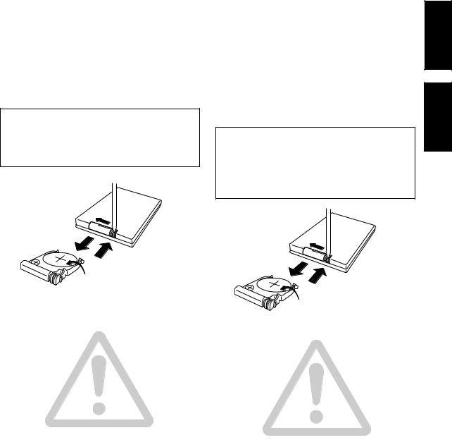
Putting the battery in the remote
1Turn over the remote control, then use a pen or pencil to release the battery cover catch.
2 Slide out the battery holder.
3Put in the supplied battery.
Take care to put it in the right way up (+ side up).
4Push the battery holder back in, and your remote is ready for use.
CAUTION
Danger of explosion if battery is incorrectly replaced.
Replace only with the same or equivalent type recommended by the manufacturer. Discard used batteries according to the manufacturer’s instructions.
1
2
4
3
Caution !
Incorrect use of batteries can result in hazards such as leakage and bursting. Please observe the following:
•Make sure that the plus and minus sides of each battery match the indications in the battery compartment.
•Remove batteries from equipment that isn’t going to be used for a month or more.
•Keep the lithium battery out of reach of children.
•If somebody swallows the lithium battery, immediately call your doctor.
•When disposing of used batteries, please comply with governmental regulations or environmental public institution’s rules that apply in your country or area.
•Be careful never to insert the battery holder in a wrong orientation, for this will result in damage.
Mise en place de la pile dans la télécommande
1Retournez la télécommande et servez-vous d’un crayon ou d’un stylo-bille pour relâcher la patte du couvercle du logement de la pile.
2 Faites glisser le porte-pile vers l’extérieur.
3Insérez la pile fournie.
Veillez à l’introduire correctement (côté + vers le haut).
4 Repoussez le porte-pile en place. La télécommande est prête.
ATTENTION
Danger d’explosion si la pile n’est pas remplacée correctement.
Remplacez-la uniquement par le même type de pile ou un type équivalent recommandé par le fabricant. Débarrassez-vous des piles usées selon les instructions du fabricant.
1
2
4
3
Attention !
Une utilisation incorrecte des piles peut provoquer un suintement d’électrolyte, voire une explosion. Respectez les points suivants:
•Assurez-vous que les pôles plus et moins de chaque pile correspondent aux indications dans le logement.
•Retirez les piles de l’appareil si vous prévoyez de ne pas l’utiliser pendant plus d’un mois.
•Gardez les piles au lithium hors de portée des petits enfants.
•Si quelqu’un devait avaler une pile au lithium, consultez immédiatement un médecin.
•Lorsque vous jetez des piles usagées, respectez les règlements gouvernementaux ou les instructions des autorités responsables de l’environnement en vigueur dans votre pays ou votre région.
•Veillez à ne jamais insérer le porte-pile dans le mauvais sens, car ceci provoquerait des dégâts.
aisçFran English
7
En/Fr
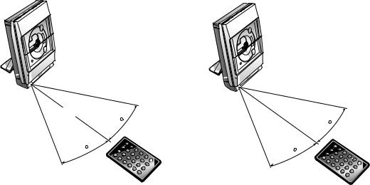
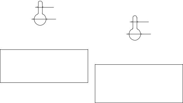
Using the remote control
The diagram below shows the operating range of the remote control.
Utilisation de la télécommande
Le schéma suivant illustre la portée utilisable de la télécommande.
23 ft.
7 meters
30
30
Keep in mind the following when using the remote control:
•Make sure that nothing is blocking the remote sensor on the unit.
•Remote operation may become unreliable if direct sunlight or fluorescent light is shining onto the remote sensor.
•Remotes for different devices can interfere with each other. Avoid using remotes for other equipment located nearby this unit.
•Replace the battery when you notice a fall off in the operating range of the remote.
7 mètres
30
30
Gardez les points suivants à l’esprit lorsque vous utilisez la télécommande:
•Assurez-vous que rien ne fait obstacle au capteur de télécommande sur l’appareil.
•La télécommande risque de ne pas fonctionner correctement si le capteur de télécommande est exposé directement au soleil ou à une lampe fluorescente.
•Les télécommandes de divers appareils peuvent créer des interférences. Évitez d’utiliser d’autres télécommandes près de cet appareil.
•Remplacez la pile si vous constatez une réduction notoire de la portée de la télécommande.
8
En/Fr

Hints on installation
We want you to enjoy using this system for years to come, so please bear in mind the following points when choosing a suitable location for it:
Do...
Use in a well-ventilated room.
Place on a solid, flat, level surface, such as a table, shelf or stereo rack.
Don’t...
Use in a place exposed to high temperatures or humidity, including near radiators and other heat-generating appliances.
Place on a window sill or other place where the system will be exposed to direct sunlight.
Use in an excessively dusty or damp environment.
Use near a television or monitor as you may experience interference—especially if the television uses an indoor antenna.
Use in a kitchen or other room where the system may be exposed to smoke or steam.
Use on a thick rug or carpet, or cover with cloth—this may prevent proper cooling of the unit.
Place on an unstable surface, or one that is not large enough to support the system fully.
Avoiding condensation problems
Condensation may form inside the system if it is brought into a warm room from outside, or if the temperature of the room rises quickly. Although the condensation won’t damage the system, it may temporarily impair its performance. For this reason you should leave it to adjust to the warmer temperature for about an hour before switching on and using.
Conseils sur l’installation
Pour profiter pleinement de ce système pendant de nombreuses années, veuillez noter les points suivants lors du choix d’un emplacement:
Veillez à...
Choisir un endroit bien ventilé.
Poser les appareils sur une surface solide, plate et de niveau, comme une table, une étagère ou un rack stéréo.
Veillez à ne pas...
Installer le système dans un endroit soumis à de fortes températures ou une humidité élevée, notamment près d’un radiateur ou d’un appareil de chauffage.
Placer le système près d’une fenêtre ou un endroit il serait exposé directement aux rayons du soleil.
Utiliser le système dans un endroit très humide ou poussiéreux.
Utiliser le système près d’un téléviseur ou d’un moniteur afin d’éviter des interférences, en particulier si le téléviseur a une antenne intérieure.
Utiliser le système dans une cuisine ou une pièce où il peut être exposé à de la fumée ou de la vapeur.
Utiliser le système sur une moquette ou un tapis épais ou le recouvrir d’un linge car ceci empêcherait son refroidissement.
Poser le système sur une surface instable ou trop étroite pour supporter toute sa base.
Évitez les problèmes de condensation
De la condensation peut se former à l’intérieur du système si vous l’apportez directement d’une pièce froide dans une pièce chaude ou si la température de la pièce augmente subitement. Bien que la condensation ne risque pas d’endommager le système, ses performances peuvent en être temporairement réduites. Il est donc conseillé de laisser le système pendant une heure environ dans son environnement avant de le mettre sous tension et de l’utiliser.
Français English
Discs compatible with this system
Any disc that displays one of the following logos should play in this system. Other discs (such as CD-ROMs) will not play in this unit. Note that this unit cannot record onto recordable discs.
This unit can play CD-R and CD-RW discs recorded with audio. However, depending on the quality of the initial recording, and the condition of the disc, you may find that not all discs will play successfully. (For example, if the disc is scratched or dirty, or if the player’s pickup lens is dirty.) Some CD-R and CD-RW discs may need to be finalized* before playing successfully.
*Check with the instruction manual of the recording component used to make the CD-R or CD-RW disc for finalization procedures.
Disques compatibles avec ce système
N’importe quel disque portant un des logos suivants peut être lu par ce système. D’autres disques (tels que les CD-Rom) ne seront pas acceptés. Notez aussi que cet appareil ne permet pas d’enregistrer sur des disques enregistrables.
Cet appareil peut reproduire des CD-R et des CD-RW sur lesquels des signaux audio ont été enregistrés. Suivant la qualité de l’enregistrement initial et l’état des disques, il est cependant possible que tous les disques ne puissent être reproduits efficacement. (Par exemple, si le disque est rayé ou souillé ou si la lentille du capteur optique du lecteur est souillée.) Il se peut également que certains CD-R et CD-RW doivent être finalisés* pour assurer une lecture efficace.
* Vérifiez les procédures de finalisation des CD-R et des CD-RW
dans le mode d’emploi du composant enregistreur utilisé.
9
En/Fr
2 Connecting Up
Connecting the CD tuner to the amplifier
Connect the CD tuner to the amplifier as described below. If you also have the optional CD-R recorder, see their accompanying instructions before following the instructions on this page. This will make connecting up several components easier.
•Important: When connecting or disconnecting the system cable, make sure that the power is switched off and the unit unplugged from the wall outlet.
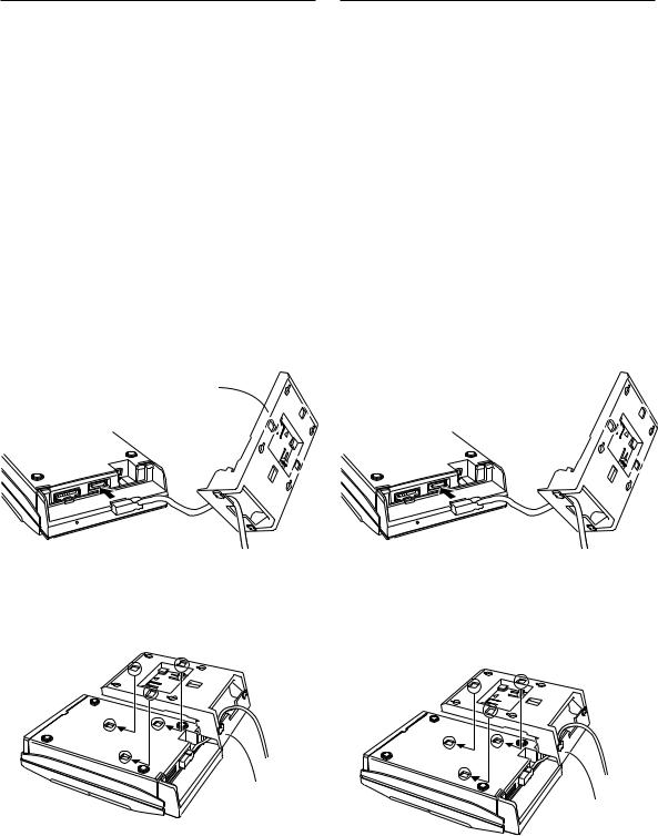
1Pass the system cable through Stand A, as shown, and connect the L-shaped end of the system cable to the socket on the underside of the CD tuner.
Line up the plug and socket before inserting. Make sure the plug clicks home.
•If you plan to wall-mount the CD tuner, connect using the other end of the system cable.
Stand A 
2Slot Stand A on to the rear side of the CD tuner.
Line up the three tabs on Stand A with the holes on the CD tuner, then slot it into place.
Stand A
2 Raccordements
Raccordement du CD tuner à l’amplificateur
Raccordez le CD tuner sur l’amplificateur comme expliqué cidessous. Si vous avez aussi la platine CR-R en option, reportezvous au mode d’emploi qui les accompagne avant de suivre les instructions de cette page. Il vous sera alors plus facile de raccorder plusieurs composants.
•Important: Avant de brancher ou de débrancher le câble de système, assurez-vous que l’alimentation est coupée et que l’appareil est débranché au niveau de sa prise secteur.
1Faites passer le câble de système par le Support A comme illustré et branchez le bout en L du câble de système sur la prise, prévue sur le fond du CD tuner.
Alignez la fiche et la prise avant l’insertion. Assurez-vous que la fiche s’enclenche avec un déclic.
•Si vous prévoyez de fixer le CD tuner sur un mur, faites la connexion en utilisant l’autre bout du câble de système.
Support A
2Glissez le Support A sur l’arrière du CD tuner
Faites correspondre les 3 taquets sur le Support A avec les orifices du CD-tuner, puis glissez pour fixer les deux éléments.
Support A
•If you have the optional CD-R recorder, connect these before attaching Stand A. (The ribbon cable can pass under Stand A to keep it tidy.)
10
•Si vous utilisez la platine CD-R en option, raccordez-les avant de fixer le Support A. (Le câble ruban peut passer sous le Support A pour le maintenir bien en place.)
En/Fr

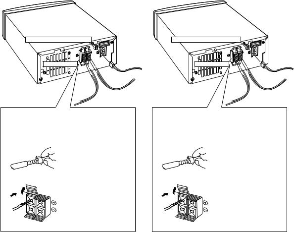
3Connect the other end of the system cable to the socket on the rear panel of the power amplifier.
Line up the plug and socket before inserting. Make sure the plug clicks home.
•If you plan to wall-mount the CD tuner, connect the L- shaped end of the system cable to the amplifier.
Ferrite core (Sound tuning part)
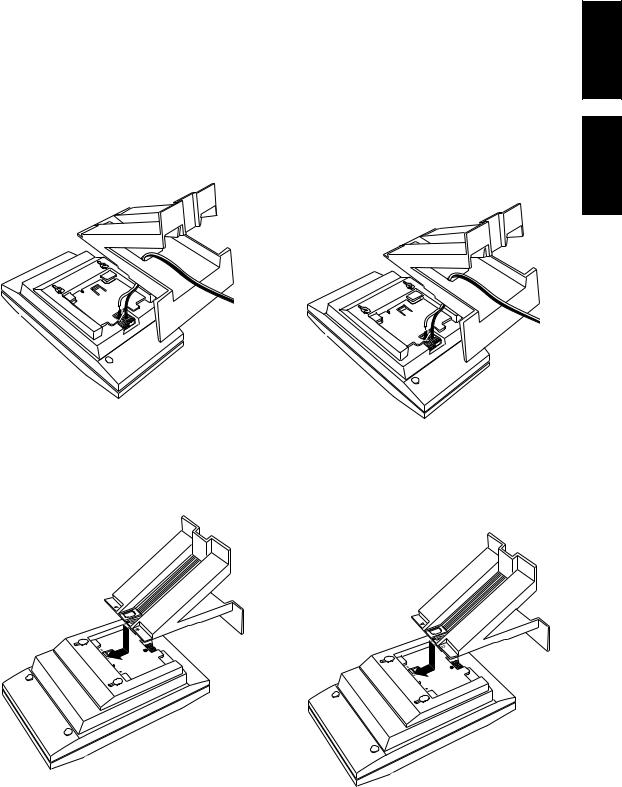
4If you plan to use the CD tuner on a table-top or shelf, attach Stand B.
Line up the tab on Stand B with the center hole on Stand A and slot it into place. Stand B will slide under the two tabs on the back of Stand A.
If you plan to wall-mount the unit, see Wall-mounting your system on page 16.
Stand B
Stand A
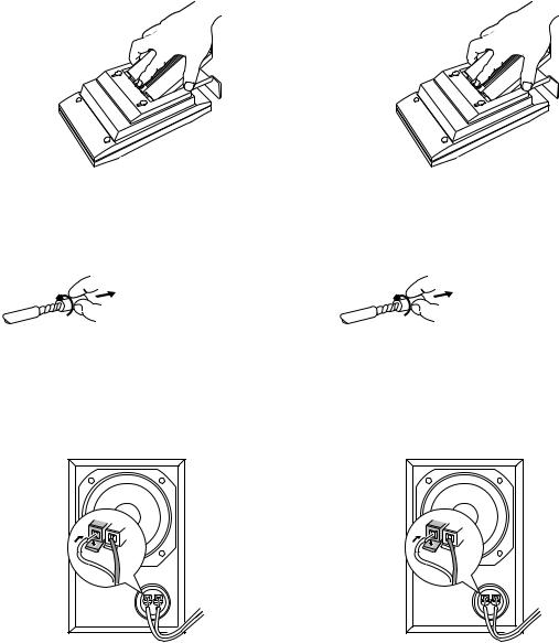
•To remove Stand B, push the center tab, as indicated, and slide off.
PUSH
•To remove Stand A, pull the tab, as indicated, and slide off.
PULL
3 Branchez l’autre bout du câble de système sur |
English |
la prise du panneau arrière de l’amplificateur |
|
la fiche s’enclenche avec un déclic. |
|
de puissance. |
|
Alignez la fiche et la prise avant l’insertion. Assurez-vous que |
|
• Si vous prévoyez de fixer le CD tuner sur un mur, branchez |
|
le bout en L du câble de système sur l’amplificateur. |
|
|
aisçFran |
Ame de ferrite (Partie d’accord sonore)
4Si vous prévoyez d’installer le CD tuner sur une table ou une étagère, fixez le Support B.
Alignez la patte du Support B avec l’orifice central du Support A et glissez-la en place. Le Support B coulissera sous les deux pattes à l’arrière du Support A.
Si vous prévoyez d’installer l’appareil sur un mur, reportez-vous à “Installation du système sur une paroi” à la page 16.
Support B
Support A
•Pour retirer le Support B, appuyez sur la patte centrale comme illustré et glissez pour détacher.
PUSH
•Pour retirer le Support A, appuyez sur la patte comme illustré et glissez pour détacher.
PULL
11
En/Fr
Connecting the speakers
The speaker system consists of stereo satellite speakers and a subwoofer for powerful bass sound. Connect the speakers to the amplifier unit as shown below.
•Important: When connecting or disconnecting speakers, make sure that the power is switched off and the unit unplugged from the wall outlet.
Connecting the satellite speakers
To get the best sound from the system, it’s important that the red
(+) and black (–) speaker terminals on the amplifier are connected to the corresponding terminals on each speaker. To help you match up the terminals correctly, the supplied speaker cable is color coded: connect the white half of the cable to the black (–) terminals, and the grey striped half to the red (+) terminals.
•Important: Make sure that the bare speaker wires cannot touch each other, or come into contact with other metal parts once the unit is switched on.
1Insert a wire into each speaker terminal on the rear of the amplifier.
Raccordement des enceintes
Le système acoustique comprend les enceintes satellites stéréo et un caisson des graves pour restituer des basses puissantes. Raccordez les enceintes sur l’amplificateur comme indiqué ci-dessous.
•Important: Avant de brancher ou de débrancher les enceintes, assurez-vous que l’alimentation est coupée et que l’appareil est débranché au niveau de sa prise secteur.
Raccordement des enceintes satellites
Pour obtenir un son optimal, les bornes d’enceintes rouges (+) et noires (–) de l’amplificateur doivent être raccordées aux bornes correspondantes de chaque enceinte. Pour faciliter le raccordement, les câbles d’enceintes fournis sont de couleurs différentes: raccordez le fil blanc du câble sur les bornes noires (–) et le fil rayé gris aux bornes rouges (+).
•Important: Assurez-vous que les extrémités dénudées des fils ne se touchent pas ou ne touchent pas des parties métalliques lorsque l’appareil est sous tension.
1Insérez un fil dans chaque borne d’enceinte à l’arrière de l’amplificateur.
Subwoofer (Super woofer) terminal
Speaker terminals
Borne de caisson des graves (Super woofer)
Bornes d’enceintes
Speaker terminal connectors
Note: Make sure that the bare speaker wires cannot touch each other, or come into contact with other metal parts unit is switched on.
Twist off the plastic shielding then twist the exposed wire strands together.
L |
To open a terminal, press |
|
|
|
down on the tab. Insert the |
|
wire, then push the tab back |
SPEAKERS |
to secure it. |
|
12
Connecteurs de borne d’enceinte Remarque: Vérifiez que les fils d’enceinte dénudés ne se touchent pas ou ne sont pas en contact avec une pièce métallique lorsque l’appareil est sous tension.
Faites tourner la gaine plastique pour l’enlever, puis torsadez les torons des fils dénudés.
L |
Pour ouvrir la borne, appuyez |
|
sur la patte. Insérez le fil, puis |
|
repoussez la patte pour |
|
immobiliser le fil. |
SPEAKERS
En/Fr
2If you plan to use your speakers on a table-top or shelf, pass the free end of each speaker cable through the speaker stand.
See the diagram under step 3, below.
3Insert the speaker wires into the terminals on the rear of each speaker.
Connect the white half of the cable to the black (–) terminals, and the grey striped half to the red (+) terminals. To open a terminal, press down on the tab. Insert the wire, then release the tab to secure it.
4If you are going to use the speakers on the stands, slot the stand into place.
If you plan to wall-mount the speakers, see Wall-mounting your system on page 16.
2Si vous prévoyez d’installer les enceintes sur une table ou une étagère, faites passer le bout libre de chaque câble d’enceinte par le support d’enceinte.
Reportez-vous au dessin sous l’étape 3 ci-après.
3Insérez les fils d’enceintes dans les bornes à l’arrière de chaque enceinte.
Raccordez le fil blanc du câble sur les bornes noires (–) et le fil rayé gris aux bornes rouges (+). Pour ouvrir la borne, appuyez sur la patte. Insérez le fil, puis relâchez la patte pour immobiliser le fil.
4Si vous prévoyez d’utiliser les enceintes sur les supports, glissez le support en place.
Si vous prévoyez d’installer les enceintes sur un mur, reportezvous à “Installation du système sur une paroi” à la page 16.
aisçFran English
13
En/Fr
•To remove the stand, press the center tab and slide the stand from the speaker.
•Pour détacher le support, appuyez sur la patte centrale et glissez le support pour le séparer de l’enceinte.
Connecting the subwoofer
Use the supplied subwoofer cable to connect the subwoofer to the amplifier.
1Twist off the plastic shielding then twist the exposed wire strands together.
2Connect the bare wire ends of the cable to the subwoofer.
The white wire connects to the black terminal; the gray wire to the red.
To open a terminal, press down on the tab. Insert the wire, then release the tab to secure it.
3Connect the other end to the amplifier.
The cable will only plug in one way; line up the plug and socket before fully inserting.
Caution!
Do not connect any other amplifier to this system. In rare cases this may result in smoke or fire.
Do not block the port opening on the front of the subwoofer. Also, do not put your hand or other object into the port: you may damage the subwoofer.
If you wish to connect speakers other than the ones supplied, use only speakers with a nominal impedance of 8 Ω . Refer to the instructions that came with your speakers if you are unsure of their impedance before connecting them and switching on.
14
Raccordement du caisson des graves
Utilisez le câble fourni avec le caisson des graves pour le raccorder à l’amplificateur.
1Faites tourner la gaine plastique pour l’enlever, puis torsadez les torons des fils dénudés.
2Branchez les bouts dénudés du câble sur le caisson des graves.
Le fil blanc se branche sur la borne noire et le fil gris sur la rouge.
Pour ouvrir la borne, appuyez sur la patte. Insérez le fil, puis relâchez la patte pour immobiliser le fil.
3Branchez l’autre bout sur l’amplificateur.
L’insertion n’est possible que dans un sens. Présentez correctement la fiche sur la prise et insérez-la à fond.
Attention!
Ne raccordez aucun autre amplificateur sur ce système. Dans certains cas rares, ceci pourrait provoquer de la fumée, voire un incendie.
N’obstruez pas l’évent sur l’avant du caisson des graves. De plus, sous peine d’endommager le caisson des graves,
n’introduisez pas la main ou un autre objet par l’ouverture.
Si vous souhaitez utiliser des enceintes autres que celles qui sont fournies, choisissez uniquement des enceintes dont l’impédance nominale est de 8 Ω . Reportez-vous aux instructions qui accompagnent les enceintes avant de les raccorder et de les mettre en service si vous hésitez quant à leur impédance.
En/Fr
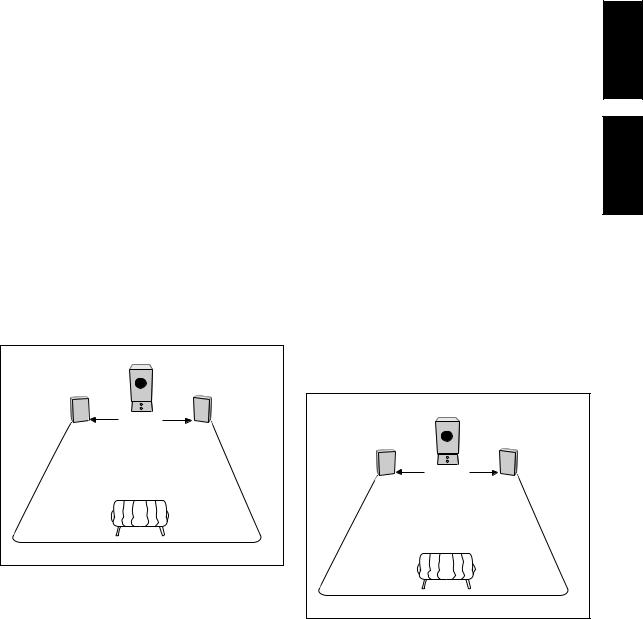
Placing the speakers
Ideally, the satellite speakers should be at about ear-level when you’re listening to them. Putting them on the floor, or mounting them very high on a wall is not recommended. For the best stereo effect, place the speakers 2–3 meters apart.
Placement of the subwoofer is not as critical as the satellite speakers because bass sounds are much less directional than middle and treble sounds. However, bear the following points in mind when choosing a suitable location.
•The subwoofer can be placed on top of the amplifier.
•As with other audio components, don’t place the subwoofer near heaters, radiators or other appliances that generate heat.
•Although you have some freedom in placement, experiment with different subwoofer locations—some will sound better than others from your usual listening position.
•Don’t use the amplifier/subwoofer on a thick rug or carpet as this can also cause ventilation problems.
Note: Avoid touching the actual speaker cone when installing or moving the subwoofer.
Left speaker |
Subwoofer |
Right speaker |
|
Amplifier |
|
|
2-3 meters |
|
|
Listening position |
|
Emplacement des enceintes
Idéalement parlant, les enceintes satellites doivent se trouver environ au niveau des oreilles lorsque vous êtes à la position d’écoute. Il n’est pas conseillé de les installer sur le plancher ou très haut sur un mur. Pour obtenir un effet stéréo optimal, séparez les deux enceintes de 2 à 3 mètres.
L’emplacement du caisson des graves n’est pas aussi critique que celui des enceintes satellites parce que les sons graves sont moins directionnels que le médium et l’aigu. Néanmoins, tenez compte des points suivants pour choisir un emplacement approprié.
•Le caisson des graves peut être posé sur l’amplificateur.
•Comme pour tout autre appareil audio, ne placez pas le caisson des graves près d’un appareil de chauffage, d’un radiateur ou d’un appareil dégageant de la chaleur.
•Bien que le choix de l’emplacement soit assez libre, placez le caisson à différents endroits pour voir quel son vous obtenez et choisissez la meilleure position.
•Pour éviter des problèmes de ventilation, ne posez pas l’amplificateur / caisson des graves sur une moquette ou un tapis épais.
Remarque: Évitez de toucher le cône de haut-parleur du caisson des graves lorsque vous l’installez ou le déplacez.
|
Caisson des |
|
Enceinte gauche |
graves |
Enceinte droite |
|
Amplificateur |
|
|
2-3 mètres |
|
|
Position d’écoute |
|
aisçFran English
15
En/Fr
Wall-mounting your system
If you prefer, you can hang the satellite speakers and/or the CD tuner (together with the optional tape deck, MD recorder and CDRecorder) on a wall. (Screws and other fixings are not supplied.)
Make sure of the following when wall-mounting any equipment:
•The wall is strong enough to support the weight.
•The screws are suitable for the wall material (concrete, wood, etc.), and are long enough to support the weight.
•You’ll still be able to easily operate the system using the remote control or the top panel controls.
•You fix all the required screws (2 for each speaker; 4 for the CD tuner and other components). Using fewer than this may make the system unstable, causing an accident.
After finding a suitable location, stick the supplied paper pattern on the wall. This makes putting the screws in the correct place very easy.
If you’re wall-mounting the CD tuner (or other optional components), attach only Stand A. If wall-mount the satellite speakers, do not attach the speaker stands.
The diagram below shows the dimensions for the screws you’ll need.
3.5mm
10mm
After fixing the screws, hang the speakers and/or other components on the wall.
Important
Pioneer bears no responsibility for accidents resulting from faulty assembly or installation, insufficient mounting strength of walls or other building fixtures, misuse or natural disasters.
Installation du système sur une paroi
Si vous le souhaitez, vous pouvez suspendre les enceintes satellites et/ou le CD tuner (ainsi que la platine-cassette, la platine MD et la platine CD-R en option) sur un mur. (Les vis et autres éléments de fixation ne sont pas fournis.)
Vérifiez les points suivants avant d’installer un équipement sur une paroi.
•La paroi est assez solide pour supporter le poids.
•Les vis conviennent au matériau de la paroi (béton, bois, etc.) et elles sont assez longues pour supporter l’appareil.
•Il est possible d’utiliser facilement le système à l’aide de la télécommande ou des commandes de son panneau supérieur.
•Vous utilisez toutes les vis nécessaires (2 pour chaque enceinte, 4 pour le CD tuner et les autres composants). L’installation risque d’être instable et de causer un accident si vous n’utilisez pas toutes les vis.
Après avoir trouvé un endroit approprié, placez le gabarit de papier contre le mur. Il est ainsi facile de localiser exactement l’emplacement des vis.
Si vous installez le CD tuner (ou d’autres composants en option) sur un mur, fixez uniquement le Support A. Si vous installez les enceintes satellites sur un mur, ne fixez pas les supports d’enceintes.
Le dessin ci-dessous indique les dimensions des vis nécessaires.
3,5mm
10mm
Après avoir fixé les vis, suspendez les enceintes et/ou les autres composants sur le mur.
Important
Pioneer n’assume aucune responsabilité en cas d’accidents, provenant d’une installation ou d’un assemblage défectueux, d’une solidité insuffisante d’un mur ou d’une paroi, d’une utilisation erronée ou de désastres naturels.
16
En/Fr
Connecting the AM and FM antennas
Connecting the supplied antennas will allow you to listen to both AM and FM radio broadcasts. If you find that reception quality is poor, an outdoor antenna should give you better sound quality— see Connecting external antennas on page 19 for more on how to do this.
•Before making or changing antenna connections, make sure that the power is switched off and the unit disconnected from the AC wall outlet.
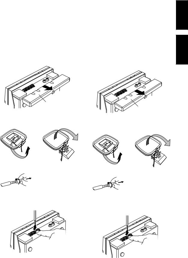
Slide off the top cover to access the antenna terminals and the auxiliary inputs (AUX IN).
Press down on the center of topcover while sliding off.
Raccordement des antennes AM et FM
En raccordant les antennes fournies, vous pourrez écouter les émissions AM et FM. Si la réception laisse à désirer, vous obtiendrez un meilleur son en raccordant une antenne externe. Reportez-vous à “Raccordement d’antennes externes” à la page 19 pour plus de détails à ce sujet.
•Avant d’effectuer ou de changer les connexions d’antenne, assurez-vous que l’alimentation est coupée et que l’appareil est débranché au niveau de sa prise secteur.
Faites glisser le panneau supérieur pour avoir accès aux bornes d’antenne et aux entrées auxiliaires (AUX IN).
Appuyez au centre du panneau supérieur en le faisant coulisser.
aisçFran English
Top cover
Panneau supérieur
AM loop antenna
1 Assemble the antenna as shown.
2 Twist the exposed wire stands together.
3Press the tabs to open the terminals then insert a wire fully into each. Release the tab to secure the wire.
Antenne cadre AM
1 Assemblez l’antenne comme illustré.
2 Torsadez les torons exposés du fil.
3Appuyez sur les pattes pour ouvrir les bornes et insérez à fond un fil dans chacune. Relâchez la patte pour immobiliser le fil.
17
En/Fr
 Loading...