

Page 1

Quick Start Guide
Guide rapide
Kurzanleitung
SC-LX83
SC-LX73
Page 2
IMPORTANT
CAUTION
RISK OF ELECTRIC SHOCK
DO NOT OPEN
The lightning flash with arrowhead symbol,
within an equilateral triangle, is intended to
alert the user to the presence of uninsulated
“dangerous voltage” within the product’s
enclosure that may be of sufficient
magnitude to constitute a risk of electric
shock to persons.
CAUTION:
TO PREVENT THE RISK OF ELECTRIC
SHOCK, DO NOT REMOVE COVER (OR
BACK). NO USER-SERVICEABLE PARTS
INSIDE. REFER SERVICING TO QUALIFIED
SERVICE PERSONNEL.
Replacement and mounting of an AC plug on the power supply cord of this unit should be performed only by qualified
service personnel.
IMPORTANT: THE MOULDED PLUG
This appliance is supplied with a moulded three pin mains plug for your safety and convenience. A 10 amp fuse is fitted in this plug. Should
the fuse need to be replaced, please ensure that the replacement fuse has a rating of 10 amps and that it is approved by ASTA or BSI to
BS1362.
Check for the ASTA mark or the BSI mark on the body of the fuse.
If the plug contains a removable fuse cover, you must ensure that it is refitted when the fuse is replaced. If you lose the fuse cover the plug
must not be used until a replacement cover is obtained. A replacement fuse cover can be obtained from your local dealer.
If the fitted moulded plug is unsuitable for your socket outlet, then the fuse shall be removed and the plug cut off and disposed of
safely. There is a danger of severe electrical shock if the cut off plug is inserted into any 13 amp socket.
If a new plug is to be fitted, please observe the wiring code as shown below. If in any doubt, please consult a qualified electrician.
IMPORTANT: The wires in this mains lead are coloured in accordance with the following code:
Blue : Neutral Brown : Live
As the colours of the wires in the mains lead of this appliance may not correspond with the coloured markings identifying the terminals in
your plug, proceed as follows;
The wire which is coloured BLUE must be connected to the terminal which is marked with the
letter N or coloured BLACK.
The wire which is coloured BROWN must be connected to the terminal which is marked with the
letter L or coloured RED.
How to replace the fuse: Open the fuse compartment with a screwdriver and replace the fuse.
The exclamation point within an equilateral
triangle is intended to alert the user to the
presence of important operating and
maintenance (servicing) instructions in the
literature accompanying the appliance.
D3-4-2-1-1_A1_En
D3-4-2-1-2-2*_A1_En
WARNING
This equipment is not waterproof. To prevent a fire or
shock hazard, do not place any container filled with
liquid near this equipment (such as a vase or flower
pot) or expose it to dripping, splashing, rain or
moisture.
D3-4-2-1-3_A1_En
WARNING
Before plugging in for the first time, read the following
section carefully.
The voltage of the available power supply differs
according to country or region. Be sure that the
power supply voltage of the area where this unit
will be used meets the required voltage (e.g., 230 V
or 120 V) written on the rear panel.
D3-4-2-1-4*_A1_En
WARNING
To prevent a fire hazard, do not place any naked flame
sources (such as a lighted candle) on the equipment.
D3-4-2-1-7a_A1_En
Operating Environment
Operating environment temperature and humidity:
+5 °C to +35 °C (+41 °F to +95 °F); less than 85 %RH
(cooling vents not blocked)
Do not install this unit in a poorly ventilated area, or in
locations exposed to high humidity or direct sunlight (or
strong artificial light)
D3-4-2-1-7c*_A1_En
Page 3
Information for users on collection and disposal of old equipment and used batteries
Symbol for
equipment
These symbols on the products, packaging, and/or accompanying documents mean
that used electrical and electronic products and batteries should not be mixed with
general household waste.
For proper treatment, recovery and recycling of old products and used batteries,
please take them to applicable collection points in accordance with your national
legislation.
By disposing of these products and batteries correctly, you will help to save valuable
Symbol examples
for batteries
resources and prevent any potential negative effects on human health and the
environment which could otherwise arise from inappropriate waste handling.
For more information about collection and recycling of old products and batteries,
please contact your local municipality, your waste disposal service or the point of sale
where you purchased the items.
These symbols are only valid in the European Union.
For countries outside the European Union:
If you wish to discard these items, please contact your local authorities or dealer and
ask for the correct method of disposal.
Pb
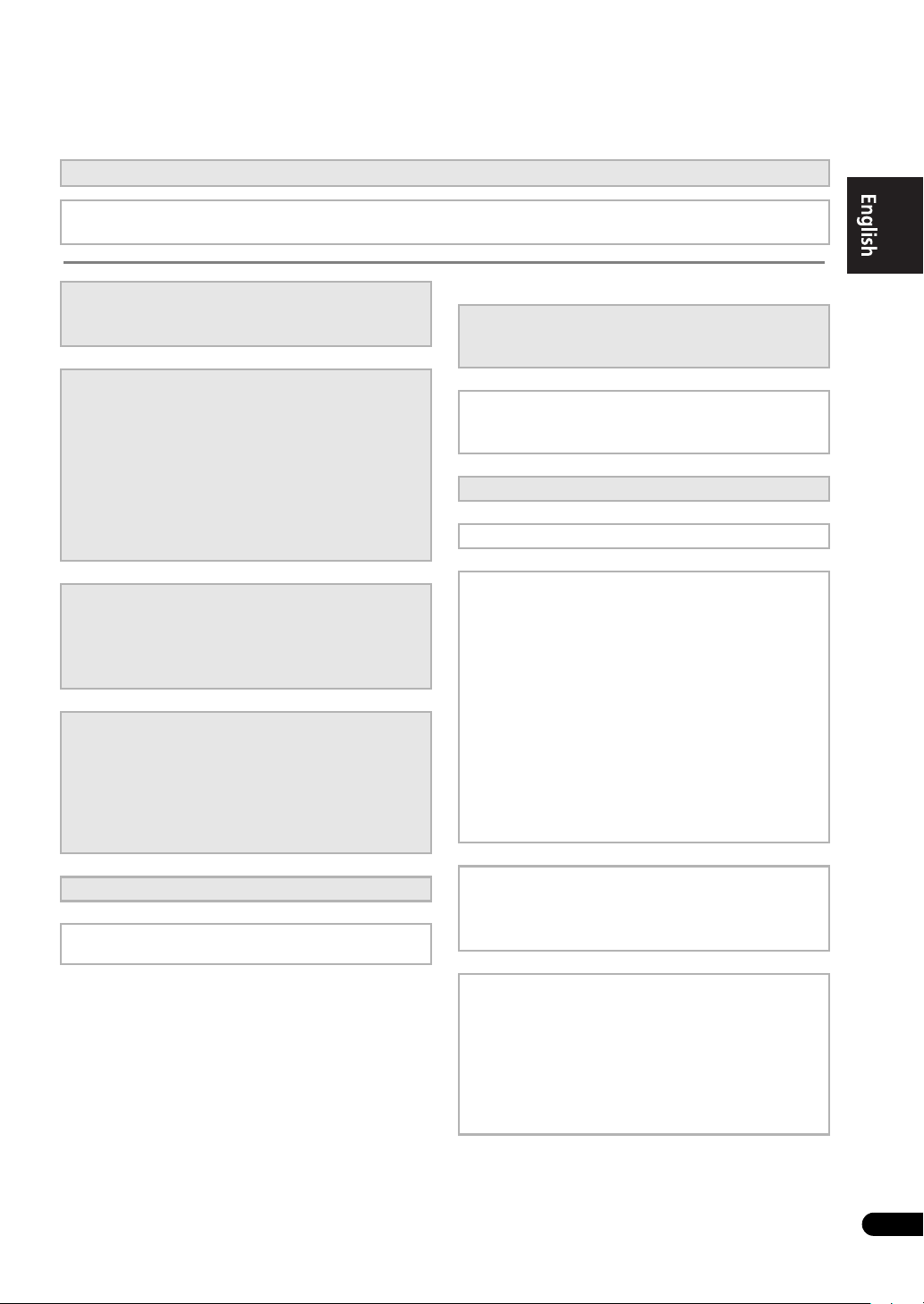
VENTILATION CAUTION
When installing this unit, make sure to leave space
around the unit for ventilation to improve heat radiation
(at least 20 cm at top, 10 cm at rear, and 20 cm at each
side).
WARNING
Slots and openings in the cabinet are provided for
ventilation to ensure reliable operation of the product,
and to protect it from overheating. To prevent fire
hazard, the openings should never be blocked or
covered with items (such as newspapers, table-cloths,
curtains) or by operating the equipment on thick carpet
or a bed.
D3-4-2-1-7b*_A1_En
K058a_A1_En
If the AC plug of this unit does not match the AC
outlet you want to use, the plug must be removed
and appropriate one fitted. Replacement and
mounting of an AC plug on the power supply cord of
this unit should be performed only by qualified
service personnel. If connected to an AC outlet, the
cut-off plug can cause severe electrical shock. Make
sure it is properly disposed of after removal.
The equipment should be disconnected by removing
the mains plug from the wall socket when left unused
for a long period of time (for example, when on
vacation).
D3-4-2-2-1a_A1_En
CAUTION
The
STANDBY/ON
switch on this unit will not
completely shut off all power from the AC outlet.
Since the power cord serves as the main disconnect
device for the unit, you will need to unplug it from the
AC outlet to shut down all power. Therefore, make
sure the unit has been installed so that the power
cord can be easily unplugged from the AC outlet in
case of an accident. To avoid fire hazard, the power
cord should also be unplugged from the AC outlet
when left unused for a long period of time (for
example, when on vacation).
D3-4-2-2-2a*_A1_En
This product is for general household purposes. Any
failure due to use for other than household purposes
(such as long-term use for business purposes in a
restaurant or use in a car or ship) and which requires
repair will be charged for even during the warranty
period.
K041_A1_En
Page 4

Thank you for buying this pioneer product.
This Quick Start Guide includes instructions for basic
connections and operations to allow simple use of the
receiver. For detailed descriptions of the receiver, see the
“Operating Instructions” provided on the included CDROM. The operating instructions can also be downloaded
from the Pioneer website (http://www.pioneer.eu).
See below for instructions on handling the CD-ROM.
Terms of Use
Copyright to data provided on this CD-ROM belongs to
Pioneer Corporation. Unauthorized transfer, duplication,
broadcast, public transmission, translation, sales,
lending or other such matters that go beyond the scope
of “personal use” or “citation” as defined by Copyright
Law may be subject to punitive actions. Permission to
use this CD-ROM is granted under license by Pioneer
Corporation.
4
En
Operating Environment
This CD-ROM can be used with Microsoft® Windows®
XP/Vista/7 and Apple Mac OS X 10.4.
Adobe Reader (Version 4.0 or later) is required to read
this CD-ROM.
Precautions For Use
This CD-ROM is for use with a personal computer. It
cannot be used with a DVD player or music CD player.
Attempting to play this CD-ROM with a DVD player or
music CD player can damage speakers or cause
impaired hearing due to the large volume.
License
Please agree to the “Terms of Use” indicated below
before using this CD-ROM. Do not use if you are
unwilling to consent to the terms of its use.
===============================================================
General Disclaimer
Pioneer Corporation does not guarantee the operation of
this CD-ROM with respect to personal computers using
any of the applicable OS. In addition, Pioneer
Corporation is not liable for any damages incurred as a
result of use of this CD-ROM and is not responsible for
any compensation. The names of private corporations,
products and other entities described herein are the
registered trademarks or trademarks of their respective
firms.
* When Using a Mac OS:
Place this CD-ROM in a CD drive and then double-click
on the CD-ROM icon to start up the application.
Contents
01 Before you start
Checking what’s in the box. . . . . . . . . . . . . . . . . . . . . . 6
Loading the batteries . . . . . . . . . . . . . . . . . . . . . . . . . . 6
Operating range of remote control unit for
infrared (IR) signal transmission . . . . . . . . . . . . . . . . . 7
Using the RF communications function
(SC-LX83 only) . . . . . . . . . . . . . . . . . . . . . . . . . . . . . . . . 7
Flow for operating the receiver with RF two-way
communications (SC-LX83 only) . . . . . . . . . . . . . . . . . . 8
Remote control (In case of SC-LX83). . . . . . . . . . . . . . . 8
Remote control (In case of SC-LX73). . . . . . . . . . . . . . 11
02 Connecting your equipment
Determining the speakers’ application. . . . . . . . . . . . 13
Placing the speakers . . . . . . . . . . . . . . . . . . . . . . . . . 15
Connecting the speakers . . . . . . . . . . . . . . . . . . . . . . 15
Installing your speaker system . . . . . . . . . . . . . . . . . . 16
Selecting the Speaker system. . . . . . . . . . . . . . . . . . . 18
About the audio connection . . . . . . . . . . . . . . . . . . . . 18
About the video converter. . . . . . . . . . . . . . . . . . . . . . 18
About HDMI . . . . . . . . . . . . . . . . . . . . . . . . . . . . . . . . 19
Connecting your TV and playback components . . . . . 20
Connecting an HDD/DVD recorder, BD recorder
and other video sources . . . . . . . . . . . . . . . . . . . . . . . 23
Connecting a satellite/cable receiver or other
set-top box . . . . . . . . . . . . . . . . . . . . . . . . . . . . . . . . . 24
Connecting the multichannel analog inputs. . . . . . . . 25
Connecting other audio components . . . . . . . . . . . . . 26
Connecting AM/FM antennas. . . . . . . . . . . . . . . . . . . 27
MULTI-ZONE setup. . . . . . . . . . . . . . . . . . . . . . . . . . . 27
Connecting to the network through
LAN interface . . . . . . . . . . . . . . . . . . . . . . . . . . . . . . . 29
Plugging in the receiver . . . . . . . . . . . . . . . . . . . . . . . 29
03 Basic Setup
Automatically conducting optimum sound tuning
(Full Auto MCACC) . . . . . . . . . . . . . . . . . . . . . . . . . . . 30
04 Basic playback
Playing a source. . . . . . . . . . . . . . . . . . . . . . . . . . . . . 33
Listening in surround sound. . . . . . . . . . . . . . . . . . . . 33
Using Auto surround, ALC, Optimum surround and
Stream Direct modes . . . . . . . . . . . . . . . . . . . . . . . . . 34
Playing an iPod . . . . . . . . . . . . . . . . . . . . . . . . . . . . . 35
Playing a USB device . . . . . . . . . . . . . . . . . . . . . . . . . 36
Listening to the radio . . . . . . . . . . . . . . . . . . . . . . . . . 36
Listening to Internet radio stations (SC-LX73 only) . . . 37
Playback with HOME MEDIA GALLERY inputs
(SC-LX83 only) . . . . . . . . . . . . . . . . . . . . . . . . . . . . . . . 37
Bluetooth® ADAPTER for Wireless Enjoyment of
Music. . . . . . . . . . . . . . . . . . . . . . . . . . . . . . . . . . . . . 38
Page 5
Flow of settings on the receiver
The unit is a full-fledged AV receiver equipped with an abundance of functions and terminals. It can be used easily
after following the procedure below to make the connections and settings.
The colors of the steps indicate the following:
Required setting item (These items are included in this Quick Start Guide.)
Setting to be made as necessary (These items are explained in the “Operating Instructions” provided on the
included CD-ROM.)
1 Before you start
• Checking what’s in the box (page 6)
• Loading the batteries (page 6)
2
Determining the speakers’ application (page
13)
• 9.1 channel surround system (Front height)
• 9.1 channel surround system (Front wide)
• 7.1 channel surround system & Speaker B
connection
• 5.1 channel surround system & Front Bi-amping
connection (High quality surround)
• 5.1 channel surround system & ZONE 2 connection
(Multi Zone)
3 Connecting the speakers
• Placing the speakers (page 15)
• Connecting the speakers (page 15)
• Installing your speaker system (page 16)
• Bi-amping your speakers (page 17)
4 Connecting the components
• About the audio connection (page 18)
• About the video converter (page 18)
• Connecting your TV and playback components
(page 20)
• Connecting AM/FM antennas (page 27)
• Plugging in the receiver (page 29)
5Power On
6 Changing the OSD display language (OSD
Language)
7 MCACC speaker settings
• Automatically conducting optimum sound tuning
(Full Auto MCACC) (page 30)
8 The Input Setup menu
(When using connections other than the
recommended connections)
9 Basic playback (page 33)
10 Switching the HDMI output
11 Adjusting the sound and picture quality as desired
• Using the various listening modes
• Better sound using Phase Control
• Better sound using Phase Control and Full Band
Phase Control (SC-LX83 only)
• Measuring the all EQ type
(SYMMETRY/ALL CH ADJ/FRONT ALIGN)
• Changing the channel level while listening
• Switching on/off the Acoustic Calibration EQ,
Sound retriever or Dialog Enhancement
• Setting the PQLS function
• Setting the Audio options
(Tone, Loudness or Sound delay, etc.)
• Setting the Video options
12 Other optional adjustments and settings
• Control with HDMI function
• The Advanced MCACC menu
• The System Setup and Other Setup menus
13 Making maximum use of the remote control
SC-LX83:
• Operating multiple receivers
• Setting the remote to control other components
• Using the RF communications function
SC-LX73:
• Operating multiple receivers
• Setting the remote to control other components
En
5
Page 6
01
Before you start
Chapter 1:
Before you start
Checking what’s in the box
Please check that you’ve received the following supplied
accessories:
In case of SC-LX83
• Setup microphone (cable: 5 m)
• Omni-directional remote control (CU-RF100)
•RF adapter
•IR blaster cable x2
• AA/LR6 dry cell batteries x4
• AM loop antenna
•FM wire antenna
• iPod cable
• Bluetooth ADAPTER (AS-BT100)
•Power cord
• Warranty card
• Operating instructions (CD-ROM)
• These quick start guide
In case of SC-LX73
• Setup microphone (cable: 5 m)
• Remote control unit
• AAA size IEC R03 dry cell batteries
(to confirm system operation) x2
• AM loop antenna
•FM wire antenna
• iPod cable
• Bluetooth ADAPTER (AS-BT100)
•Power cord
• Warranty card
• Operating instructions (CD-ROM)
• These quick start guide
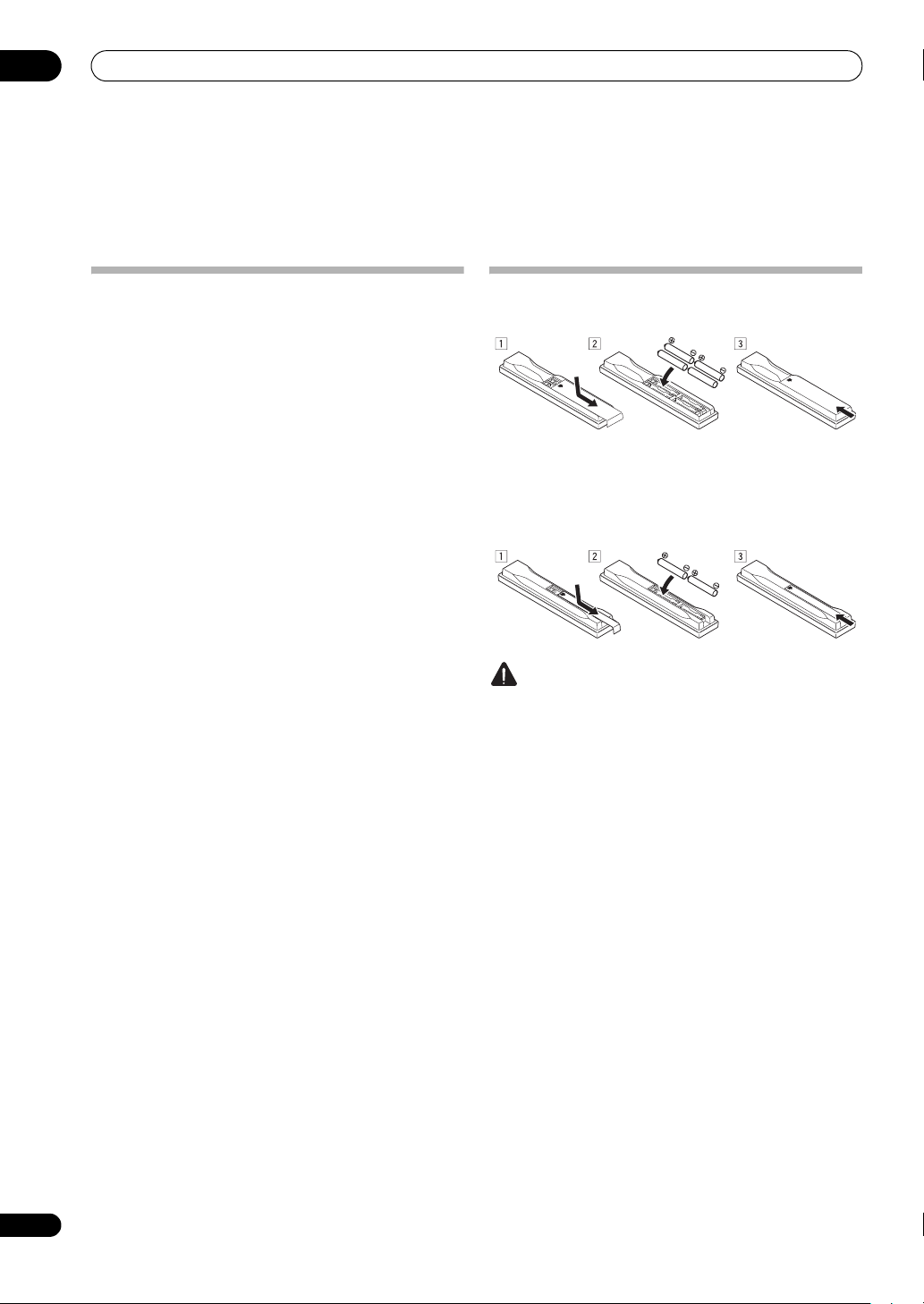
Loading the batteries
In case of SC-LX83
In case of SC-LX73
The batteries included with the unit are to check initial
operations; they may not last over a long period.
We recommend using alkaline batteries that have a
longer life.
CAUTION
Incorrect use of batteries may result in such hazards as
leakage and bursting. Observe the following precautions:
• Never use new and old batteries together.
• Insert the plus and minus sides of the batteries
properly according to the marks in the battery case.
• Batteries with the same shape may have different
voltages. Do not use different batteries together.
• When disposing of used batteries, please comply
with governmental regulations or environmental
public instruction’s rules that apply in your country or
area.
• WARNING
Do not use or store batteries in direct sunlight or
other excessively hot place, such as inside a car or
near a heater. This can cause batteries to leak,
overheat, explode or catch fire. It can also reduce the
life or performance of batteries.
6
En
Page 7
Before you start
R
T
01
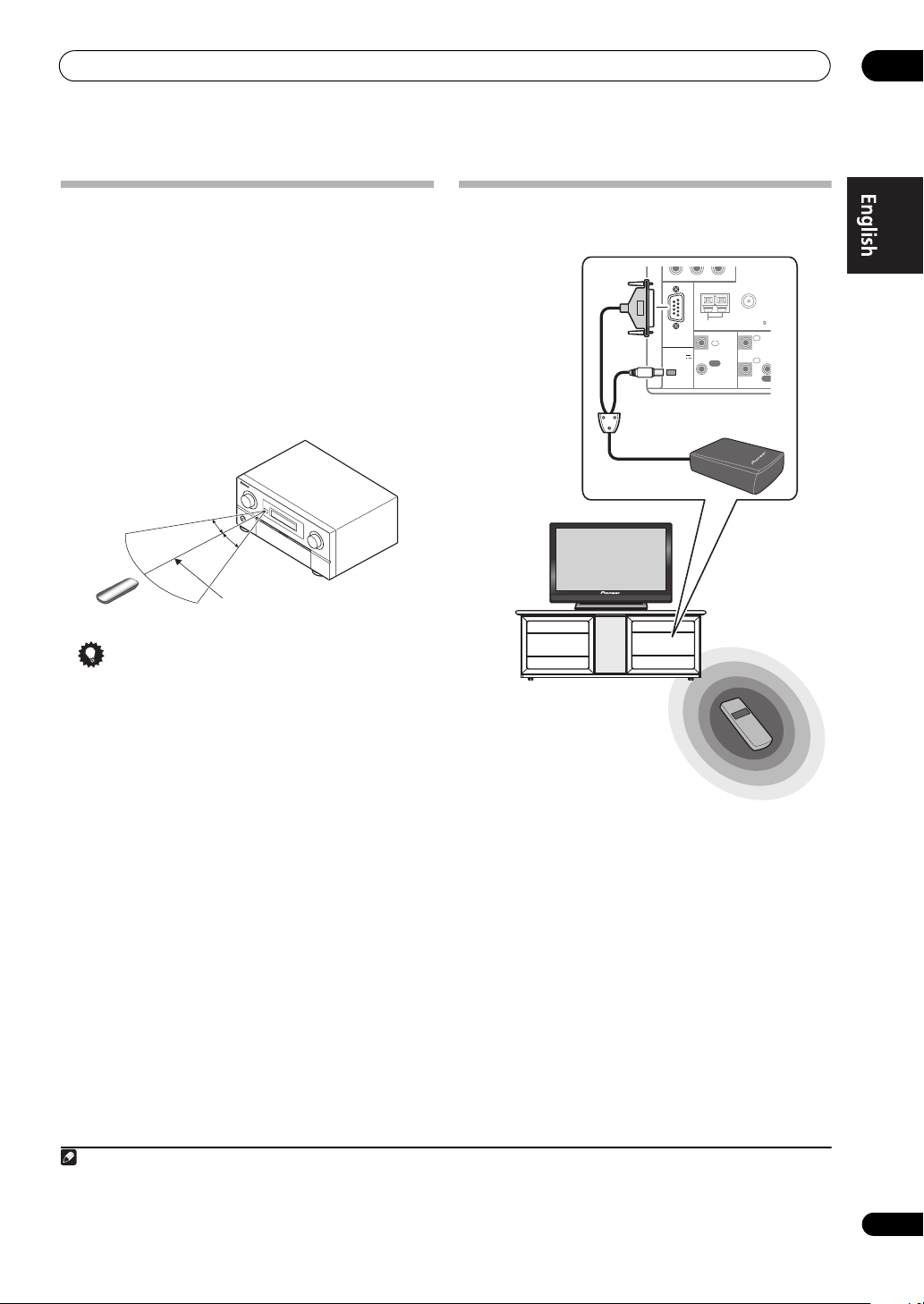
Operating range of remote control unit for infrared (IR) signal transmission
The remote control may not work properly if:
• There are obstacles between the remote control and
the receiver’s remote sensor.
• Direct sunlight or fluorescent light is shining onto the
remote sensor.
• The receiver is located near a device that is emitting
infrared rays.
• The receiver is operated simultaneously with another
infrared remote control unit.
30°
30°
7 m
Tip
• By connecting an RF adapter to the RS-232C and CURF100 terminals (SC-LX83) / EXTENSION terminals
(SC-LX73), the CU-RF100 omni-directional remote
control can be used for RF two-way communications
with the receiver.
communications function (SC-LX83 only) below.
1
For details, see Using the RF
Using the RF communications function
(SC-LX83 only)
Y
PRP
B
ANTENNA
FM UNBAL 75 AM LOOP
I
IN
1
2
IN
OU
Operation of the receiver or
other components placed in a
rack is possible
Operation is possible in any
direction the remote control is
pointed (360°)
RS-232C
(
OUTPUT 5 V
)
150 mA MAX
CU-RF100
Receiver
RF Adapter
Remote control operation
CONTROL
IN
OUT
With RF two-way communications, the information of the
receiver’s display can be displayed on the remote control
in your hands and the remote control can be operated
without worrying about obstacles or the direction in
which the remote control is pointing.
2
For details, see
Flow for operating the receiver with RF two-way
communications (SC-LX83 only) on page 8.
Note
1 The RF adapter and CU-RF100 omni-directional remote control are included with the SC-LX83, sold separately with the SC-LX73.
2 The maximum line-of-sight distance for RF two-way communications is abou t 10 meters. This line-of-sight communications distance is a rough
indication, and may differ according to the surrounding environment.
7
En
Page 8
01
Before you start
Flow for operating the receiver with RF
two-way communications
This remote control unit is set for operations using
infrared signals upon shipment from the factory. To set it
for RF operations, take the steps below (See the
Operating Instructions in CD-ROM for detail).
1 Connecting the RF adapter to the RS-232C and CU-
RF100 terminals.
See Using the RF communications function (SC-
LX83 only) on page 7.
2
Setting the ‘
receiver.
1 Switch on the receiver.
2 Push gently on the lower third portion of the
receiver’s front panel, then press HOME MENU.
3 Use / to select System Setup
ENTER
4 Use / to select Other Setup
ENTER
5 Use / to select RF Remote Setup
ENTER
6 Use / to select ON
MENU
3 Pairing the RF adapter and remote control.
1 Press the SETTING button on the front of the RF
adapter.
RF adapter’s LED blinks red.
2 While pressing MULTI OPERATION, press
VIDEO PARAMETER on the remote control.
The remote display shows PAIRING.
3 Press ENTER on the remote control.
When pairing is successful, SUCCESS is displayed and
pairing is completed. RF adapter’s LED lights green.
4
Setting ‘RECEIVER MAIN’ to ‘
remote control unit’s ‘
1 While pressing MULTI OPERATION, press
HOME MENU.
The remote display shows SETUP MENU.
2 Use / to select IR/RF SELECT, then press
ENTER.
3 Use / to select
ENTER.
4 Use / to select RF MODE, then press
5 Press and hold MULTI OPERATION for a couple
of seconds
RF Remote Setup
.
.
.
.
IR/RF SELECT
RECEIVER MAIN
to exit and store the operation
(SC-LX83 only)
’ to ‘ON’ with the
, then press
, then press
, then press
RF MODE
’ setting.
, then press
HOME
’ for the
, then press
ENTER.
.
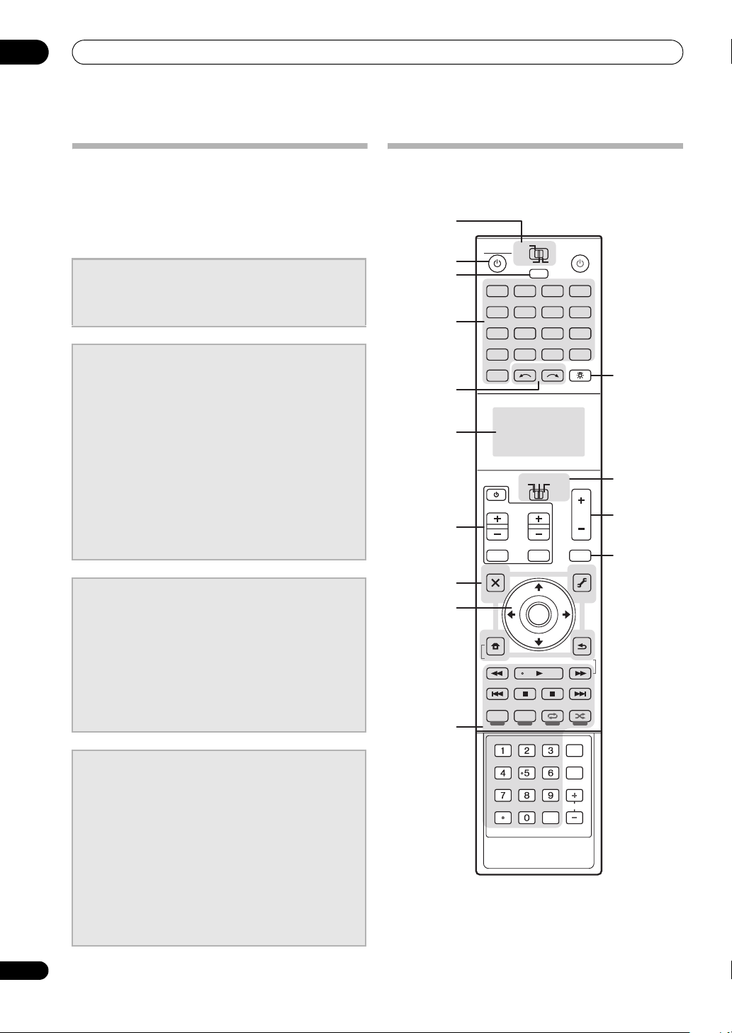
Remote control (In case of SC-LX83)
This section explains how to operate the remote control
for the receiver.
1
MAIN
RECEIVER SOURCE
ZONE2
2
3
BD
TV
4
USB
iPod
PHONO
AUX
5
6
CH
7
TV CONTROL
INPUT MUTE
AUDIO
PARAMETER
8
TOP MENU
BAND
9
PRESET PRESET
CATEGORY
iPod CTRL
STATUS
THX PQLSMPX MEMORY
AUTO/ALC/
DIRECT
10
PGM MENU
SIGNAL SEL SLEEP AUDIO
A.ATT
D.ACCESS
CLR
LIST
HOME
MENU
3
MULTI
OPERATION
BDR
DVD
NET RADIO
HMG
CD
OPTION
12
TUNER
MULTI CH
VIDEO
IN
INPUT SELECT LIGHT
SOURCE
TV
RECEIVER
VOL
TUNE
TOOLS
ENTER
TUNE
PHASE CTRL CH LEVEL
STANDARD ADV SURR
STEREO
DIMMER
SBch MCACC
HDMI OUT
CLASS
ENTER
HDMIDVR
ADAPTER
CD-R
VOL
MUTE
VIDEO
PARAMETER
T.EDIT
GUIDE
RETURN
PTY SEARCH
INFO
DISP
CH
11
12
13
14
8
En
Page 9

Before you start
01
The remote has been conveniently color-coded according
to component control using the following system:
• White – Receiver control, TV control
• Blue – Other controls (see the Operating Instructions
in CD-ROM for detail)
1 MULTI-ZONE operation selector switch
Switch to perform operations in the main zone, ZONE 2
and ZONE 3.
2
RECEIVER
This switches between standby and on for this receiver.
3
MULTI OPERATION
Use this button to perform multi operations.
4 Input function buttons
Press to select control of other components. There is no
AUX input on this receiver, so the AUX button cannot be
used.
5
INPUT SELECT
Use to select the input function.
6 Character display
This display shows information when transmitting
control signals. The remote screen’s display differs when
operating the receiver by sending infrared signals from
the remote control and when operating it by RF two-way
communications. For details, see Remote control display
on page 10.
7
TV CONTROL
buttons
These buttons are dedicated to control the TV assigned to
the TV operation selector switch.
8 Receiver setting buttons
Set the remote control operation selector switch to
RECEIVER first to access:
AUDIO PARAMETER – Use to access the Audio
options.
VIDEO PARAMETER – Use to access the Video
options.
HOME MENU – Use to access the Home Menu.
RETURN – Press to confirm and exit the current
menu screen.
9
////ENTER
Use the arrow buttons when setting up your surround
sound system and the Audio or Video options.
10 Receiver Control buttons
Set the remote control operation selector switch to
RECEIVER first to access:
STATUS – Press to check selected receiver settings.
PHASE CTRL – Press to switch on/off Phase Control
or Full Band Phase Control.
CH LEVEL – Press repeatedly to select a channel,
then use / to adjust the level.
THX – Press to select a Home THX listening mode.
PQLS – Press to select the PQLS setting.
AUTO/ALC/DIRECT – Switches between Auto
Surround (page 34), Auto Level Control, Optimum
Surround mode and Stream Direct mode (page 34).
STEREO – Switches between stereo playback and
Front Stage Surround Advance modes.
STANDARD – Press for Standard decoding and to
switch various modes (2 Pro Logic, Neo:6, etc.)
(page 33).
ADV SURR – Use to switch between the various
surround modes (page 34).
SIGNAL SEL – Use to select an input signal.
SLEEP – Use to put the receiver in sleep mode and
select the amount of time before sleep.
DIMMER – Dims or brightens the display.
A.ATT – Attenuates (lowers) the level of an analog
input signal to prevent distortion.
SBch – With this receiver, SBch cannot be used.
MCACC – Press to switch between MCACC presets.
HDMI OUT – Switch the HDMI output terminal.
11
LIGHT
Press to turn on/off the illumination for the buttons.
1
12 Remote control operation selector switch
Set to RECEIVER to operate the receiver, TV or SOURCE
to operate the TV or the source device.
When this switch is set to RECEIVER, the receiver can be
controlled (used to select the white commands). Also use
this switch to set up surround sound.
13
VOL +/–
Use to set the listening volume.
14
MUTE
Mutes the sound or restores the sound if it has been
muted (adjusting the volume also restores the sound).
Note
1 Press and hold in the LIGHT button for 5 seconds to change the illumination mode 1 or 2. When set to LIGHT MODE 2 (default), the
illumination only lights when the remote control LIGHT button is pressed. When switched to LIGHT MODE 1, the illumination lights whenever
buttons are operated. Setting LIGHT MODE 1 will shorten the service life of the batteries.
9
En
Page 10
01
6
Before you start
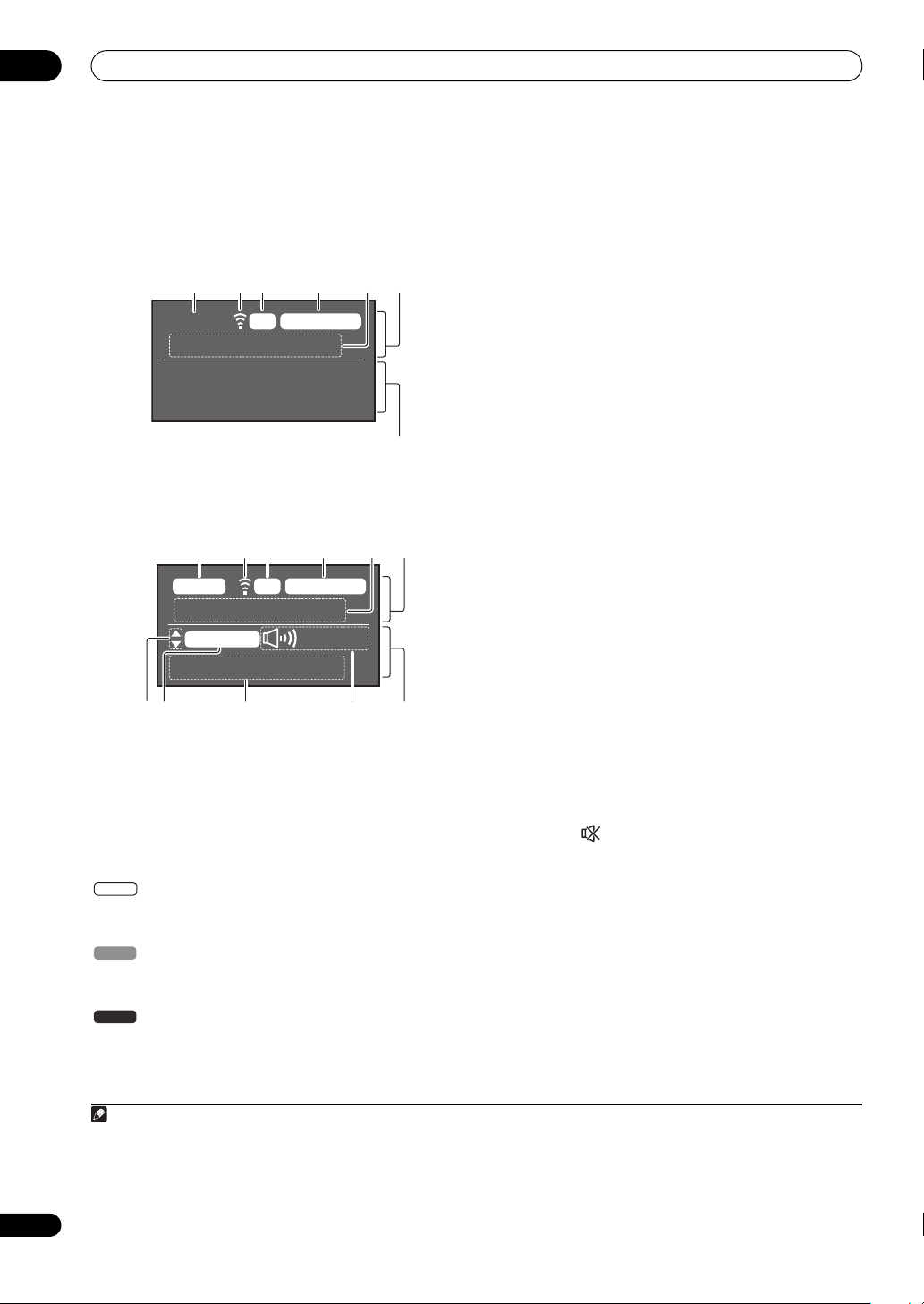
Remote control display
1
Remote control display for infrared signal
transmission (default)
1 2 3 4
MAIN SOURCEIR
5
iPod/USB
7
Remote control display for RF two-way
communications
2
1 2 3 4
MAIN
56
RCV CTRLRF
AV RECEIVER
VIDEO
+12.
0dB
1. Adv MCACC
89
1 Remote control operating zone indicator
This indicates which zone the remote control is currently
set to operate. The display indicates the setting of the
MULTI-ZONE operation selector switch.
Only when RF two-way communications:
The box display here indicates the communication status
between this remote control unit and the receiver.
MAIN
(White box with black letters): Two-way
communications are established and the receiver’s
power is on.
(Gray box with black letters): Two-way
MAIN
communications are established and the receiver’s
power is off.
(White letters only): Two-way communications are
MAIN
not working well. In this case, the area indicating the
receiver’s status (12) is not displayed.
10 11 12
2 Remote control code sending indicator
This appears when signals are sent from the remote
control.
3 Remote control code sending mode indicator
This indicates whether remote control codes are being
sent by infrared (IR) signal or RF communications.
4 Remote control operation indicator
This indicates which operation mode the remote control
is currently set to. The display indicates the setting of the
remote control operation selector switch.
5 Input function and sending code indicator
This indicates what input function can currently be
operated with the remote control. Also, when a button is
pressed and its operation code is sent, the name of that
code is displayed.
6 Area indicating the remote control's status
7 Nothing displayed
Nothing is displayed here when the remote control code
sending mode is set to IR.
8 Scroll indicators
Light when there are more selectable items when making
the various settings.
9 Receiver input indicator
This indicates the input function currently selected for
the receiver’s zone.
10 Receiver display
The same information as on the receiver’s display is
displayed here.
11 Master volume display
This indicates the volume of the receiver’s main zone
using, as an icon and in decibels (dB). When the sound
is muted, the icon is displayed.
12 Area indicating the receiver’s status
10
En
Note
1 The display lights when a remote control operation is performed, then turns off after 20 seconds if no other operation is performed. When in
the Remote Setup mode, the setup is canceled and the display turns off if no operation is performed for 1 minute.
2 • This is displayed when an RF adapter is connected to the receiver and paired with the remote control. For details, see Using the RF
communications function on the Operating Instructions in CD-ROM.
• Depending on the communications environment, two-way communications may not work well and the remote control display may not reflect
the receiver’s status.
Page 11
Before you start
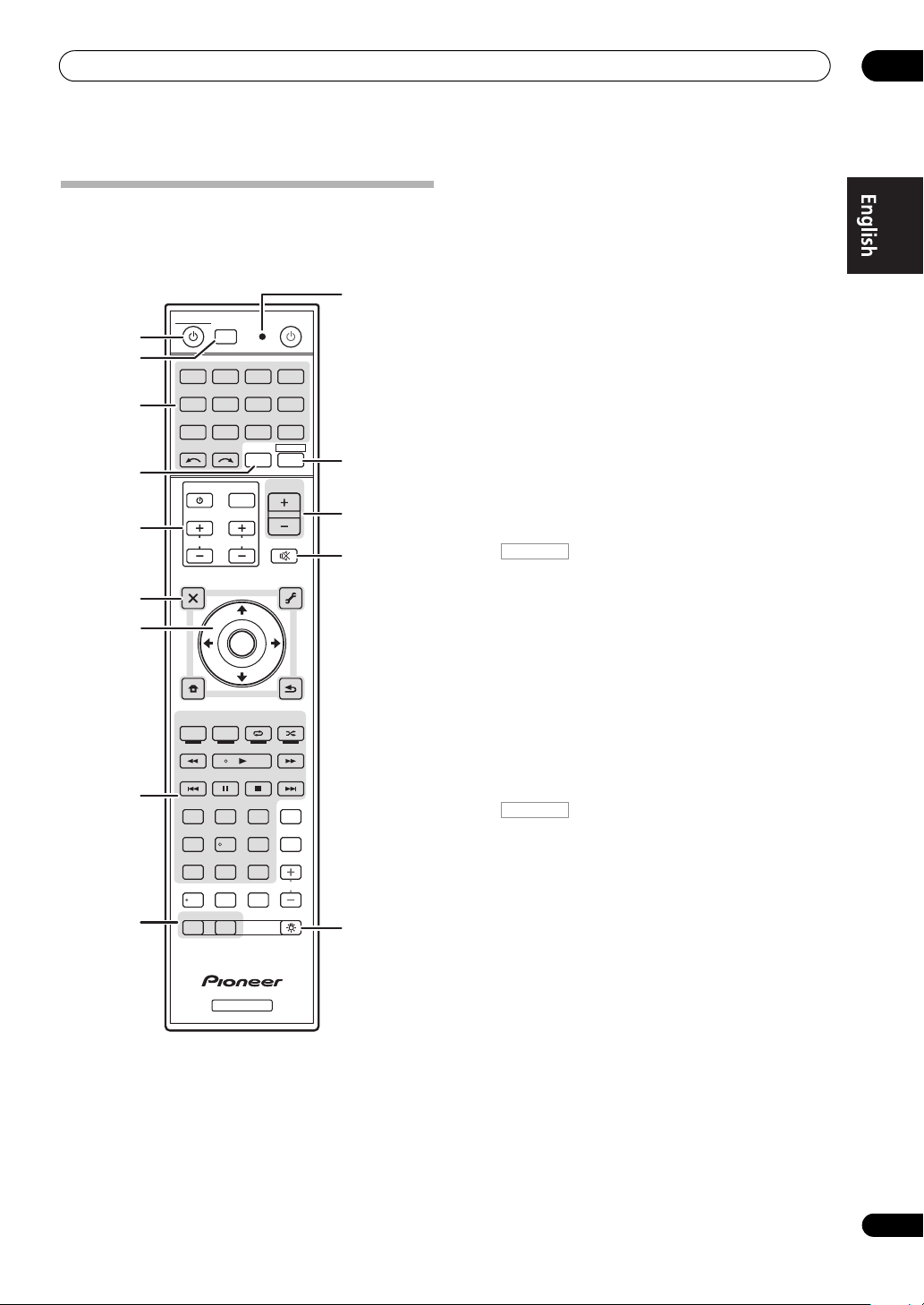
Remote control (In case of SC-LX73)
This section explains how to operate the remote control
for the receiver.
10
MULTI
1
2
3
OPERATION
R.SETUP
BD DVD
CDTV
iPod
USB TUNER VIDEO CD-R
INPUT
SELECT TV CTRL
4
5
6
7
8
9
The remote has been conveniently color-coded according
to component control using the following system:
• White – Receiver control, TV control
• Blue – Other controls (see the Operating Instructions
in CD-ROM for detail)
TV CONTROL
CH
AUDIO
PARAMETER
LIST
TOP MENU
BAND GUIDE
PRESET
PTY
SEARCH
HOME
MENU
iPod CTRL
AUTO
/
ALC /
PGM
DIRECT
STEREO
HDD DVD
PHASE
/
DTV MPX PQLS
TV
HDMI OUT
SIGNAL SEL
MCACC SLEEP
CH LEVEL A.ATT DIMMER
79
D.ACCESS
/ CLR
ZONE 2 ZONE 3 LIGHT
RECEIVER
SOURCERECEIVER
DVR/BDR HDMI
ADAPTERNET RADIO
RECEIVER
MASTER
VOLUME
INPUT
VOL
MUTE
VIDEO
PARAMETER
TUNE
TOOLS
T.EDIT
ENTER
TUNE
213
546
8
0
MEMORY
STANDARD
CTRL STATUSTHX
CLASS
ENTER
PRESET
RETURN
MENU
ADV SURR
AUDIO
INFO
DISP
CH
11
12
13
14
1 RECEIVER
This switches between standby and on for this receiver.
2
MULTI OPERATION – Use to perform multi
operations.
R.SETUP – Use to input the preset code when making
remote control settings and to set the remote control
mode.
3 Input function buttons
Press to select control of other components.
Use INPUT SELECT to select the input function.
4
TV CTRL
Set the preset code of your TV’s manufacturer when
controlling the TV.
5
TV CONTROL
buttons
These buttons are dedicated to control the TV assigned to
the TV CTRL button.
6 Receiver setting buttons
Press first to access:
RECEIVER
AUDIO PARAMETER – Use to access the Audio
options.
VIDEO PARAMETER – Use to access the Video
options.
HOME MENU – Use to access the Home Menu.
RETURN – Press to confirm and exit the current
menu screen.
7
////ENTER
Use the arrow buttons when setting up your surround
sound system and the Audio or Video options.
8 Receiver Control buttons
Press first to access:
RECEIVER
AUTO/ALC/DIRECT –
Surround (
page 34
Stream Direct mode (
Switches between Auto
), Auto Level Control mode and
page 34).
STEREO – Switches between stereo playback and
Front Stage Surround Advance modes.
STANDARD – Press for Standard decoding and to
switch various modes (2 Pro Logic, Neo:6, etc.)
(page 33).
ADV SURR – Use to switch between the various
surround modes (page 34).
THX – Press to select a Home THX listening mode.
PHASE CTRL – Press to switch on/off Phase Control.
STATUS – Press to check selected receiver settings.
PQLS – Press to select the PQLS setting.
HDMI OUT – Switch the HDMI output terminal.
SIGNAL SEL – Use to select an input signal.
MCACC – Press to switch between MCACC presets.
01
11
En
Page 12

01
Before you start
SLEEP – Use to put the receiver in sleep mode and
select the amount of time before sleep.
CH LEVEL – Press repeatedly to select a channel,
then use / to adjust the level.
A.ATT – Attenuates (lowers) the level of an analog
input signal to prevent distortion.
DIMMER – Dims or brightens the display.
9
MULTI-ZONE
Switch to perform operations in ZONE 2 and ZONE 3.
10 Remote control LED
Lights when a command is sent from the remote control.
RECEIVER
11
Switches the remote to control the receiver (used to
select the white commands).
Switch to perform operations in the main zone.
Also use this button to set up surround sound.
12
MASTER VOLUME +/–
Use to set the listening volume.
13
MUTE
Mutes the sound or restores the sound if it has been
muted (adjusting the volume also restores the sound).
14
Press to turn on/off the illumination for the buttons. The
way the buttons light can be selected from four modes
(see the Operating Instructions in CD-ROM for detail).
select buttons
12
En
Page 13
Connecting your equipment
Chapter 2:
Connecting your equipment
02
This receiver provides you with many connection
possibilities, but it doesn’t have to be difficult. This
chapter explains the kinds of components you can
connect to make up your home theater system.
Important
• Illustration shows the SC-LX83, however connections
for the SC-LX73 are the same except where noted.
CAUTION
• Before making or changing the connections, switch
off the power and disconnect the power cord from the
power outlet. Plugging in should be the final step.
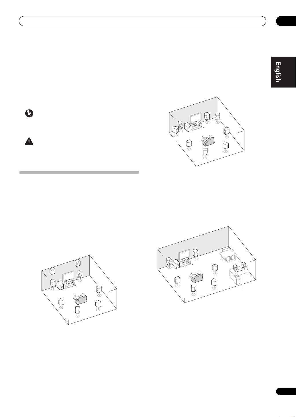
Determining the speakers’ application
This unit permits you to build various surround systems,
in accordance with the number of speakers you have.
• Be sure to connect speakers to the front left and right
channels (L and R).
• It is also possible to only connect one of the surround
back speakers (SB) or neither.
Choose one from Plans [A] to [E] below.
[A] 9.1 channel surround system (Front height)
*Default setting
• Speaker System setting: Normal(SB/FH)
FHR
FHL
R
[B] 9.1 channel surround system (Front wide)
• Speaker System
FWL
setting: Normal(SB/FW)
R
L
C
SW
SL
SBL
FWR
SR
SBR
This plan replaces the left and right front height speakers
shown in [A] with the left and right front wide speakers
(FWL/FWR).
This surround system produces a true-to-life sound over
a wider area.
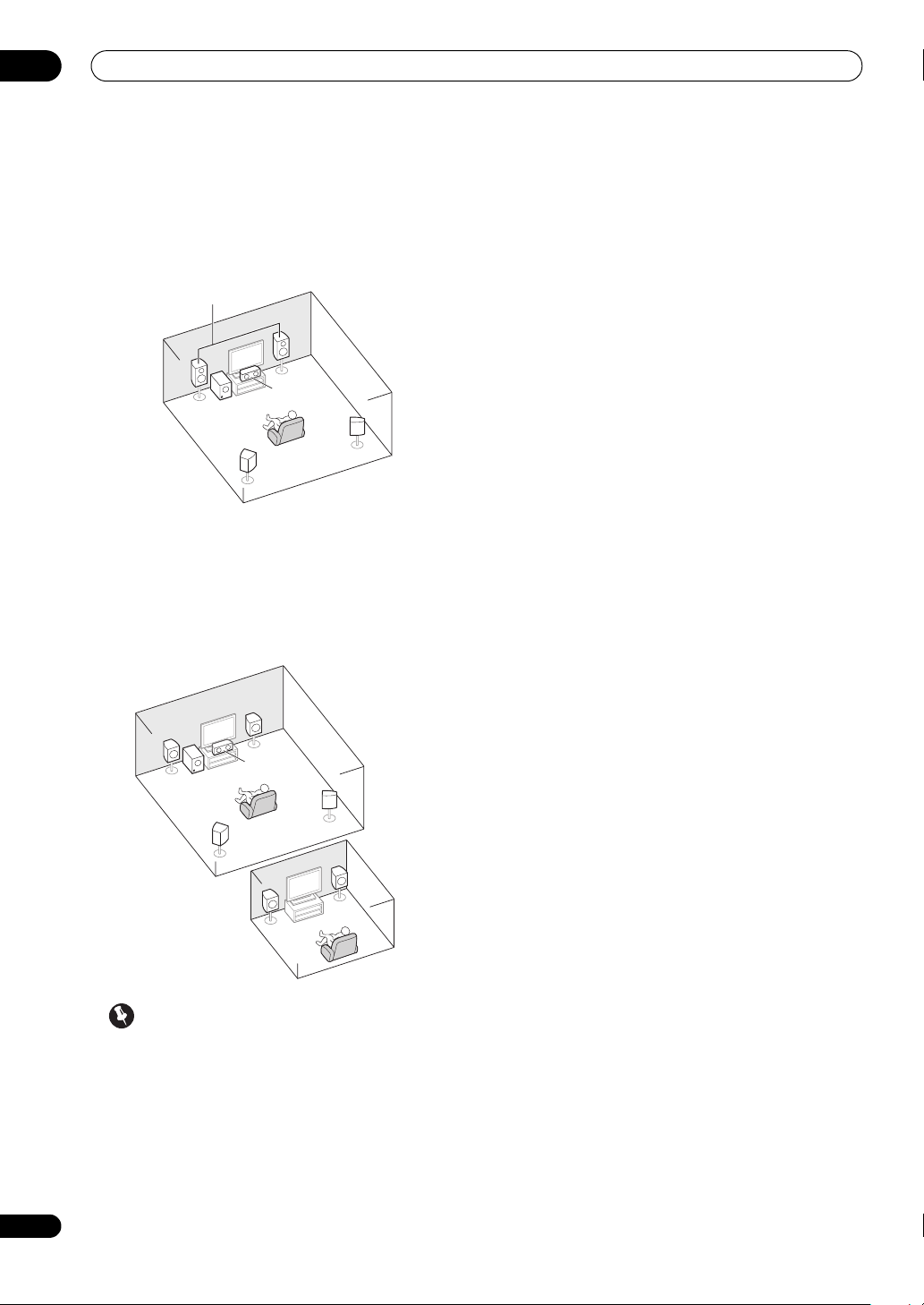
[C] 7.1 channel surround system & Speaker B
connection
• Speaker System setting: Speaker B
R
L
R
L
SW
C
SR
L
SW
SL
C
SBL
SR
SBR
A 9.1 ch surround system connects the left and right
front speakers (L/R), the center speaker (C), the left and
right front height speakers (FHL/FHR), the left and right
surround speakers (SL/SR), the left and right surround
back speakers (SBL/SBR), and the subwoofer (SW).
This surround system produces a more true-to-life sound
from above.
SL
SBL
SBR
Speaker B
With these connections you can simultaneously enjoy
5.1-channel surround sound in the main zone with stereo
playback of the same sound on the B speakers. The same
connections also allow for 7.1-channel surround sound
in the main zone when not using the B speakers.
13
En
Page 14
02
Connecting your equipment
[D] 5.1 channel surround system & Front Biamping connection (High quality surround)
• Speaker System setting: Front Bi-Amp
Bi-amping connection of the front speakers for high
sound quality with 5.1-channel surround sound.
Front Bi-Amp
R
L
SW
C
SR
SL
[E] 5.1 channel surround system & ZONE 2
connection (Multi Zone)
• Speaker System setting: ZONE 2
With these connections you can simultaneously enjoy
5.1-channel surround sound in the main zone with stereo
playback on another component in ZONE 2. (The
selection of input devices is limited.)
R
L
Main zone
Other speaker connections
• Your favorite speaker connections can be selected
even if you have fewer than 5.1 speakers (except front
left/right speakers).
• When not connecting a subwoofer, connect speakers
with low frequency reproduction capabilities to the
front channel. (The subwoofer’s low frequency
component is played from the front speakers, so the
speakers could be damaged.)
•
After connecting, be sure to conduct the Full Auto
MCACC (speaker environment setting) procedure.
See Automatically conducting optimum sound tuning
(Full Auto MCACC) on page 30.
14
En
C
SW
SR
Sub zone
R
ZONE 2
SL
L
Important
•The Speaker System setting must be made if you
use any of the connections shown above other than
[A] (see Speaker system setting on Operating
Instructions in CD-ROM).
• Sound does not come through simultaneously from
the front height, front wide, speaker B and surround
back speakers. Output speakers are different
depending on the input signal or listening mode.
Page 15
Connecting your equipment
02
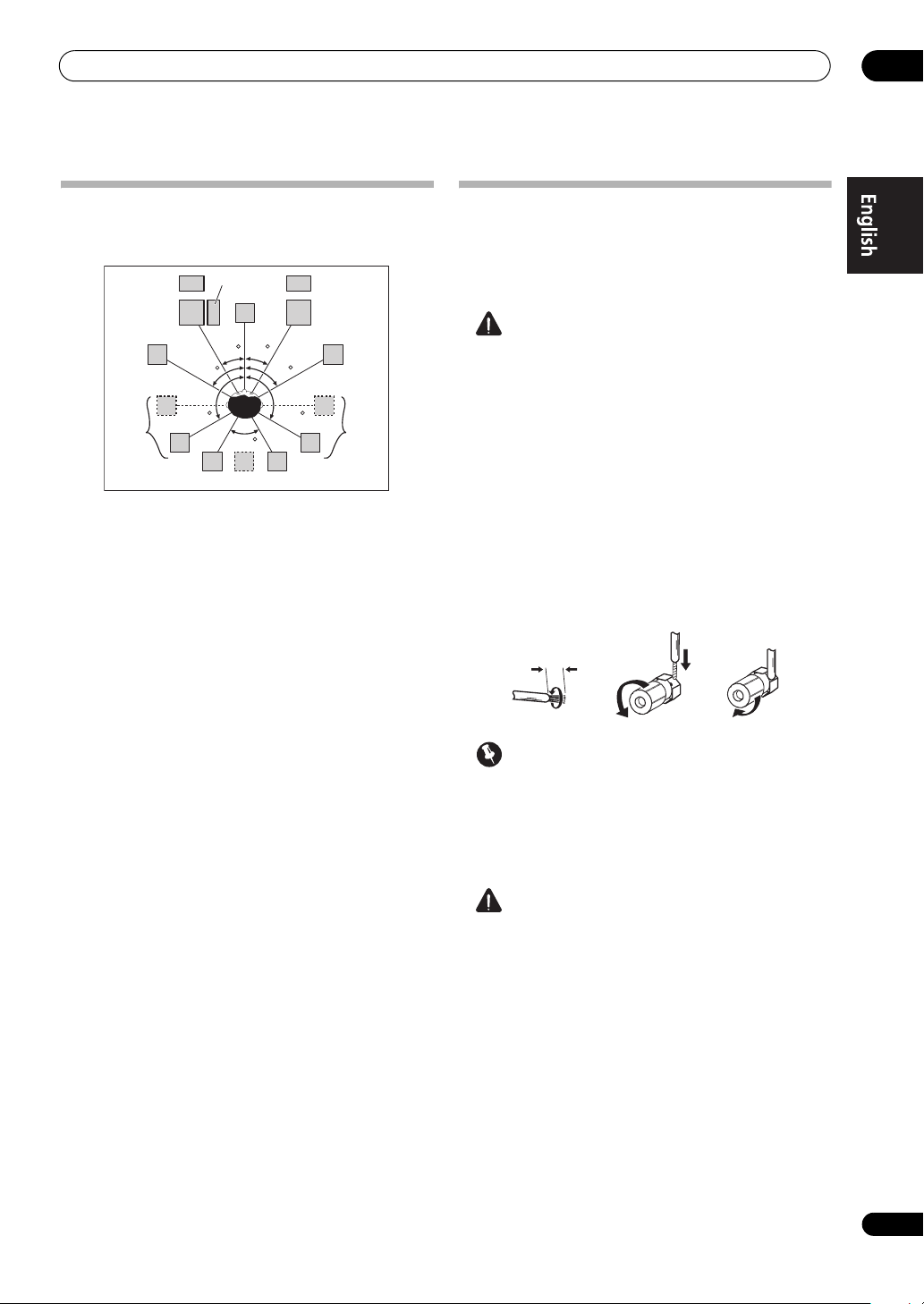
Placing the speakers
Refer to the chart below for placement of the speakers
you intend to connect.
FHL
FWL
SL
SW
C
L
30 30
60
120 120
60
SBL
SB
• Place the surround speakers at 120º from the center.
If you, (1) use the surround back speaker, and, (2)
don’t use the front height speakers / front wide
speakers, we recommend placing the surround
speaker right beside you.
• If you intend to connect only one surround back
speaker, place it directly behind you.
• Place the left and right front height speakers at least
one meter directly above the left and right front
speakers.
FHR
R
FWR
60
SR
SBR
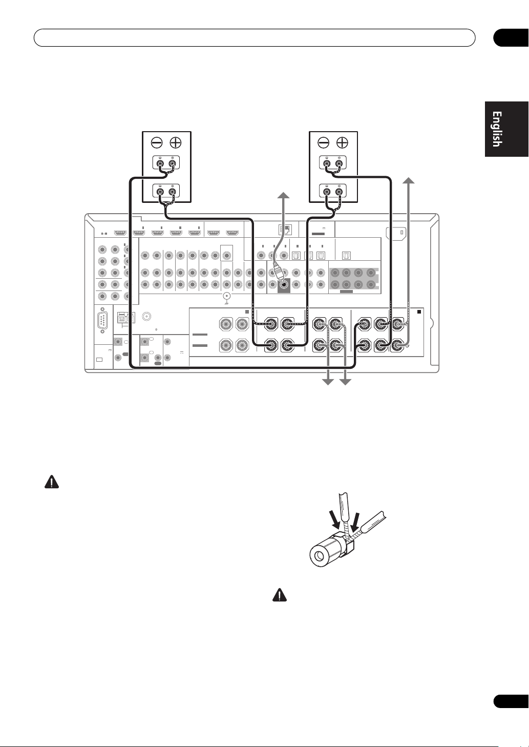
Connecting the speakers
Each speaker connection on the receiver comprises a
positive (+) and negative (–) terminal. Make sure to
match these up with the terminals on the speakers
themselves.
CAUTION
• These speaker terminals carry HAZARDOUS LIVE
voltage. To prevent the risk of electric shock when
connecting or disconnecting the speaker cables,
disconnect the power cord before touching any
uninsulated parts.
• Make sure that all the bare speaker wire is twisted
together and inserted fully into the speaker terminal.
If any of the bare speaker wire touches the back panel
it may cause the power to cut off as a safety measure.
Bare wire connections
1 Twist exposed wire strands together.
2 Loosen terminal and insert exposed wire.
3 Tighten terminal.
fig. A fig. B fig. C
10 mm
(fig. C)
(fig. A)
(fig. B)
Important
• Please refer to the manual that came with your
speakers for details on how to connect the other end
of the speaker cables to your speakers.
• Use an RCA cable to connect the subwoofer. It is not
possible to connect using speaker cables.
CAUTION
• Make sure that all speakers are securely installed.
This not only improves sound quality, but also
reduces the risk of damage or injury resulting from
speakers being knocked over or falling in the event of
external shocks such as earthquakes.
15
En
Page 16
02
Connecting your equipment
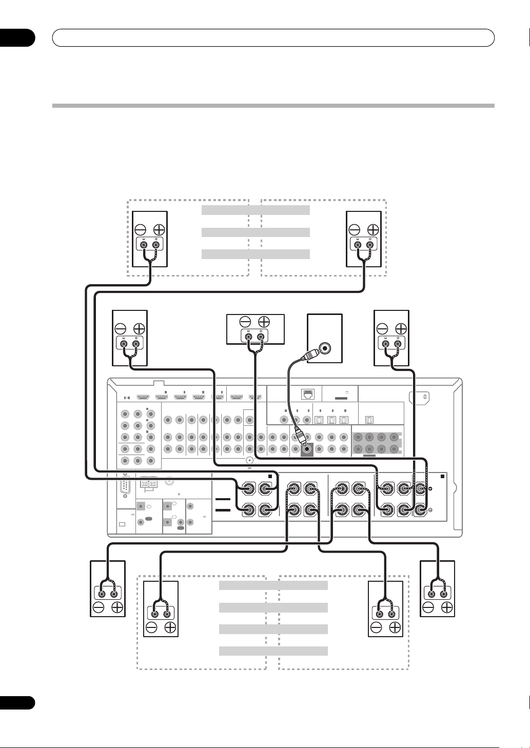
Installing your speaker system
At the very least, front left and right speakers only are necessa ry. N ote tha t you r ma in s urround speakers should always
be connected as a pair, but you can connect just one surround back speaker if you like (it must be connected to the
left surround back terminal).
Standard surround connection
The front height terminals can also be used
for the front wide and Speaker B speakers.
Front right
HDMI
ASSIGNABLE
1 4
COMPONENT VIDEO
ASSIGNABLE
Y
RS-232C
(
OUTPUT 5 V
)
150 mA MAX
CU-RF100
IN
IN
IN
B
ANTENNA
IN
(
DVD
1
(
DVR/BDR
2
(
VIDEO
3
MONITOR OUT
ZONE 2 OUT
PRP
CONTROL
IN
OUT
)
)
)
Front height right
Front wide right
INBD
1IN2IN3
ZONE2
ZONE3
DVDINTV/SATINVIDEOINDVR/BDR PHONO
OUT
OUT
FM UNBAL 75 AM LOOP
IR 12 V
IN
1
TRIGGER
1
(OUTPUT
IN
2
12 V
TOTAL
2
150 mA MAX)
OUT
Front height setting
Front wide setting
Speaker B setting
Center
OUT 1
IN
(
)
CONTROL
4
MONITOR
OUT
IN
OUT IN
SIGNAL
GND
FRONT HEIGHT/WIDE/
R
SPEAKERS
SELECTABLE
SEE INSTRUCTION
MANUAL
SELECTABLE
VOIR LE MODE
D'EMPLOI
Front height left
Front wide left
Speaker B - leftSpeaker B - right
Subwoofer
LINE LEVEL
INPUT
OUT 2
(
)
LAN
10/100
COAXIAL
1
2
IN
IN
(
)
(CD)
DVD
VIDEO
CD-R/TAPE
CD
IN
FRONT CENTERSURROUND SURR BACK
IN
OUT
SURROUND BACK
B
LR L R L R L
CAUTION:
SPEAKER IMPEDANCE 6 Ω - 16 Ω .
ATTENTION:
ENCEINTE D'IMPEDANCE DE 6 Ω - 16 Ω .
IN
(
CD-R
SUBWOOFER
ADAPTER PORT
(
OUTPUT 5 V
100 mA MAX
ASSIGNABLEASSIGNABLE
OPTICAL
1
2
3
IN
IN
IN
(
)
(
)
)
(
TV/SAT
DVR/BDR
VIDEO
FH/FW
(Single)
PRE OUT
(Single)
Front left
)
3
OUT
)
FRONT CENTER
SURROUND SURR BACK
SUBWOOFER
SURROUND FRONT CENTER
MULTI CH IN
AC IN
L
R
A
16
En
Surround right
The surround back terminals can also be
used for ZONE 2.
5.1 ch surround setting
6.1 ch surround setting
Not connected
7.1 ch surround setting
Surround back right
ZONE 2 setting
ZONE 2 - Right
Not connectedNot connected
Surround back
Surround back left
ZONE 2 - Left
Surround left
Page 17
Connecting your equipment
Bi-amping your speakers
Front right
Bi-amp compatible
speaker
High
Front left
High
Bi-amp compatible
speaker
02
Low
OUT 1
HDMI
ASSIGNABLE
1 4
COMPONENT VIDEO
ASSIGNABLE
Y
RS-232C
(
OUTPUT 5 V
)
150 mA MAX
CU-RF100
IN
IN
IN
B
ANTENNA
IN
(
DVD
1
(
DVR/BDR
2
(
VIDEO
3
MONITOR OUT
ZONE 2 OUT
PRP
CONTROL
IN
OUT
)
)
INBD
1IN2IN3
)
ZONE2
ZONE3
OUT
OUT
FM UNBAL 75 AM LOOP
IR 12 V
1
IN
2
IN
OUT
IN
4
DVDINTV/SATINVIDEOINDVR/BDR PHONO
TRIGGER
1
(OUTPUT
12 V
TOTAL
2
150 mA MAX)
OUT IN
SPEAKERS
SELECTABLE
SEE INSTRUCTION
MANUAL
SELECTABLE
VOIR LE MODE
D'EMPLOI
(
CONTROL
MONITOR
R
OUT 2
)
OUT
VIDEO
CD
IN
IN
SIGNAL
GND
FRONT HEIGHT/WIDE/
Bi-amping is when you connect the high frequency driver
and low frequency driver of your speakers to different
amplifiers for better crossover performance. Your
speakers must be bi-ampable to do this (having separate
terminals for high and low) and the sound improvement
will depend on the kind of speakers you’re using.
CAUTION
• Most speakers with both High and Low terminals
have two metal plates that connect the High to the
Low terminals. These must be removed when you are
bi-amping the speakers or you could severely
damage the amplifier. See your speaker manual for
more information.
• If your speakers have a removable crossover network,
make sure you do not remove it for bi-amping. Doing
so may damage your speakers.
Subwoofer
(
)
10/100
LAN
COAXIAL
IN
(
DVD
CD-R/TAPE
IN
OUT
B
L RLRLRL
CAUTION:
SPEAKER IMPEDANCE 6 Ω - 16 Ω .
ATTENTION:
ENCEINTE D'IMPEDANCE DE 6 Ω - 16 Ω .
OPTICAL
1
2
3
IN
IN
IN
)
(
(CD)
(
)
TV/SAT
CD-R
FRONT CENTERSURROUND SURR BACK
SUBWOOFER
SURROUND BACK
Surround right
Low
ADAPTER PORT
(
OUTPUT 5 V
)
100 mA MAX
ASSIGNABLEASSIGNABLE
1
2
3
IN
IN
)
(
)
DVR/BDR
(Single)
(Single)
OUT
(
)
VIDEO
FRONT CENTER
FH/FW
PRE OUT
SUBWOOFER
SURROUND FRONT CENTER
Surround left
SURROUND SURR BACK
MULTI CH IN
AC IN
L
R
A
Bi-wiring your speakers
Your speakers can also be bi-wired if they support biamping.
• With these connections, the Speaker System setting
makes no difference.
• To bi-wire a speaker, connect two speaker cords to
the speaker terminal on the receiver.
CAUTION
• Don’t connect different speakers from the same
terminal in this way.
• When bi-wiring as well, heed the cautions for biamping shown at the left.
Center
17
En
Page 18
02
18
En
Connecting your equipment
ZONE 2 setup
Selecting the Speaker system
The front height terminals can be used for front wide and
Speaker B connections, in addition to for the front height
speakers. Also, the surround back terminals can be used
for bi-amping and ZONE 2 connections, in addition to for
the surround back speakers. Make this setting according
to the application.
Front height setup
*Default setting
1 Connect a pair of speakers to the front height
speaker terminals.
See Standard surround connection on page 16.
2 If necessary, select ‘
Speaker System
See Speaker system setting on Operating Instructions in
CD-ROM to do this.
Front wide setup
1 Connect a pair of speakers to the front height
speaker terminals.
See Standard surround connection on page 16.
2 Select ‘
menu.
See Speaker system setting on Operating Instructions in
CD-ROM to do this.
Normal(SB/FW)
Speaker B setup
You can listen to stereo playback in another room.
1 Connect a pair of speakers to the front height
speaker terminals.
See Standard surround connection on page 16.
2 Select ‘
See Speaker system setting on Operating Instructions in
CD-ROM to do this.
Speaker B
Bi-Amping setup
Bi-amping connection of the front speakers for high
sound quality with 5.1-channel surround sound.
1 Connect bi-amp compatible speakers to the front
and surround back speaker terminals.
See Bi-amping your speakers on page 17.
2 Select ‘
menu.
See Speaker system setting on Operating Instructions in
CD-ROM to do this.
Note
1 • If the video signal does not appear on your TV, try adjusting the resolution settings on your component or display. Note that some
components (such as video game units) have resolutions that may not be converted. In this case, try switching Digital Video Conversion (in
Setting the Video options on Operating Instructions in CD-ROM) OFF.
• The signal input resolutions that can be converted from the component video input for the HDMI output are 480i/576i, 480p/576p, 720p and
1080i. 1080p signals cannot be converted.
• Only signals with an input resolution of 480i/576i can be converted from the component video input for the composite MONITOR OUT
terminals.
Front Bi-Amp
menu.
’ from the
Normal(SB/FH)
’ from the
Speaker System
’ from the
Speaker System
’ from the
Speaker System
menu.
With these connections you can simultaneously enjoy
5.1-channel surround sound in the main zone with stereo
playback on another component in ZONE 2.
1 Connect a pair of speakers to the surround back
speaker terminals.
See Standard surround connection on page 16.
2 Select ‘
See Speaker system setting on Operating Instructions in
CD-ROM to do this.
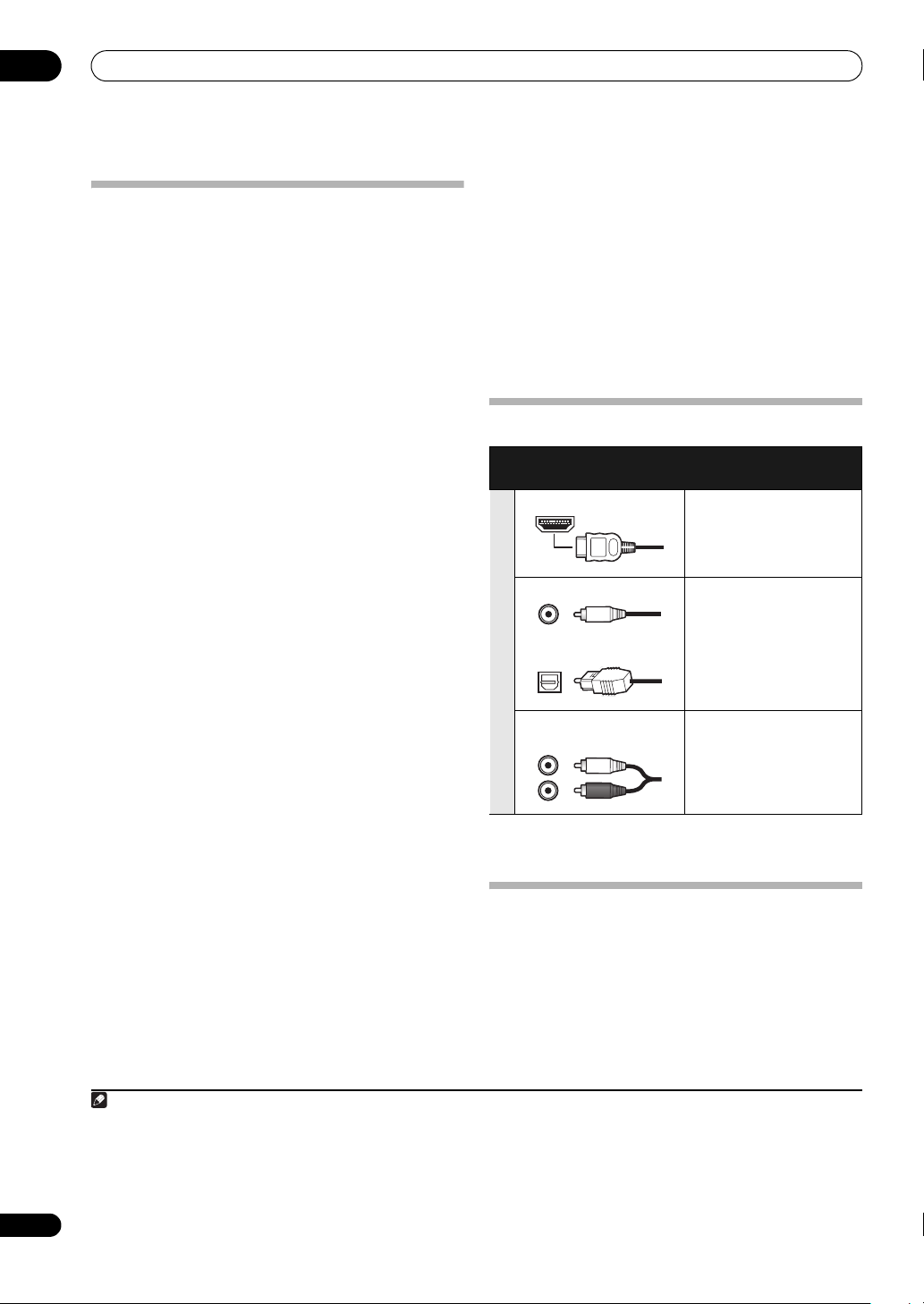
About the
Sound signal priority
• With an HDMI cable, video and audio signals can be
ZONE 2
’ from the
Speaker System
audio connection
Types of cables and
terminals
HDMI HD audio
Digital (Coaxial) Conventional digital audio
Digital (Optical)
RCA (Analog)
(White/Red)
transferred in high quality over a single cable.
Transferable audio
signals
Conventional analog audio
About the video converter
The video converter ensures that all video sources are
output through all of the MONITOR VIDEO OUT jacks.
The only exception is HDMI: since this resolution cannot
be downsampled, you must connect your monitor/TV to
the receiver’s HDMI video outputs when connecting this
video source.
1
menu.
Page 19
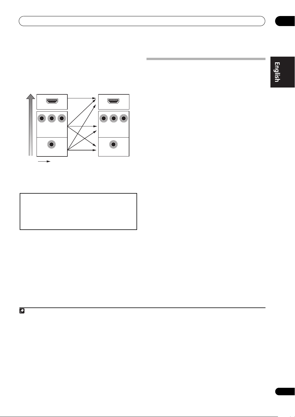
Connecting your equipment
If several video components are assigned to the same
input function (see The Input Setup menu on Operating
Instructions in CD-ROM), the converter gives priority to
HDMI, component, then composite (in that order).
Terminal for connection
with source device
HDMI IN HDMI OUT
High picture quality
YPBP
COMPONENT
VIDEO IN
R
VIDEO IN
Video signals can be output
• For optimal video performance, THX recommends
switching Digital Video Conversion (in Setting the
Video options on Operating Instructions in CD-ROM)
OFF.
This product incorporates copyright protection technology that is
protected by U.S. patents and other intellectual property rights.
Use of this copyright protection technology must be authorized by
Rovi Corporation, and is intended for home and other limited
viewing uses only unless otherwise authorized by Rovi
Corporation. Reverse engineering or disassembly is prohibited.
Terminal for connection
with TV monitor
B
P
Y
COMPONENT VIDEO
MONITOR OUT
MONITOR OUT
VIDEO
P
R
About HDMI
1
The HDMI connection transfers uncompressed digital
video, as well as almost every kind of digital audio.
This receiver incorporates High-Definition Multimedia
®
Interface (HDMI
This receiver supports the functions described below
through HDMI connections.
) technology.
2
• Digital transfer of uncompressed video (contents
protected by HDCP (1080p/24, 1080p/60, etc.))
• 3D signal transfer
• Deep Color signal transfer
• x.v.Color signal transfer
• Audio Return Channel
3
3
3
3
• Input of multi-channel linear PCM digital audio
signals (192 kHz or less) for up to 8 channels
• Input of the following digital audio formats:
4
– Dolby Digital, Dolby Digital Plus, DTS, High bitrate
audio (Dolby TrueHD, DTS-HD Master Audio, DTSHD High Resolution Audio), DVD-Audio, CD, SACD
(DSD signal), Video CD, Super VCD
• Synchronized operation with components using the
Control with HDMI function (see Control with HDMI
function on Operating Instructions in CD-ROM).
HDMI, the HDMI logo and High-Definition Multimedia
Interface are trademarks or registered trademarks of HDMI
Licensing, LLC in the United States and other countries.
“x.v.Color” and x.v.Color logo are trademarks of Sony
Corporation.
02
Note
1 • An HDMI connection can only be made with DVI-equipped components compatible with both DVI and High Bandwidth Digital Content
Protection (HDCP). If you choose to connect to a DVI connector, you will need a separate adaptor (DVIHDMI) to do so. A DVI connection,
however, does not support audio signals. Consult your local audio dealer for more information.
• If you connect a component that is not compatible with HDCP, an HDCP ERROR message is displayed on the front panel display. Some
components that are compatible with HDCP still cause this message to be displayed, but so long as there is no problem with displaying video
this is not a malfunction.
• Depending on the component you have connected, using a DVI connection may result in unreliable signal transfers.
• This receiver supports SACD, Dolby Digital Plus, Dolby TrueHD and DTS-HD Master Audio. To take advantage of these formats, however,
make sure that the component connected to this receiver also supports the corresponding format.
2 • Use a High Speed HDMI
• When an HDMI cable with a built-in equalizer is connected, it may not operate properly.
3 Signal transfer is only possible when connected to a compatible component.
4 • HDMI format digital audio transmissions require a longer time to be recognized. Due to this, interruption in the audio may occur when
switching between audio formats or beginning playback.
• Turning on/off the device connected to this unit's HDMI OUT terminal during playback, or disconnecting/connecting the HDMI cable during
playback, may cause noise or interrupted audio.
®
cable. If an HDMI cable other than a High Speed HDMI® cable is used, it may not work properly.
19
En
Page 20
02
O
N
W
Connecting your equipment
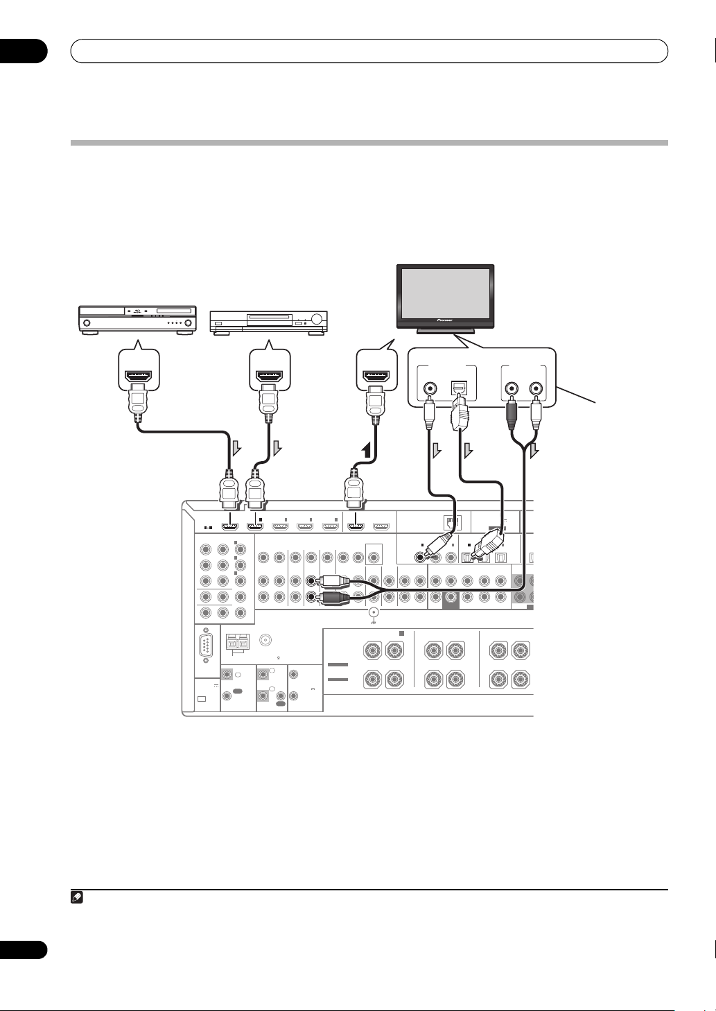
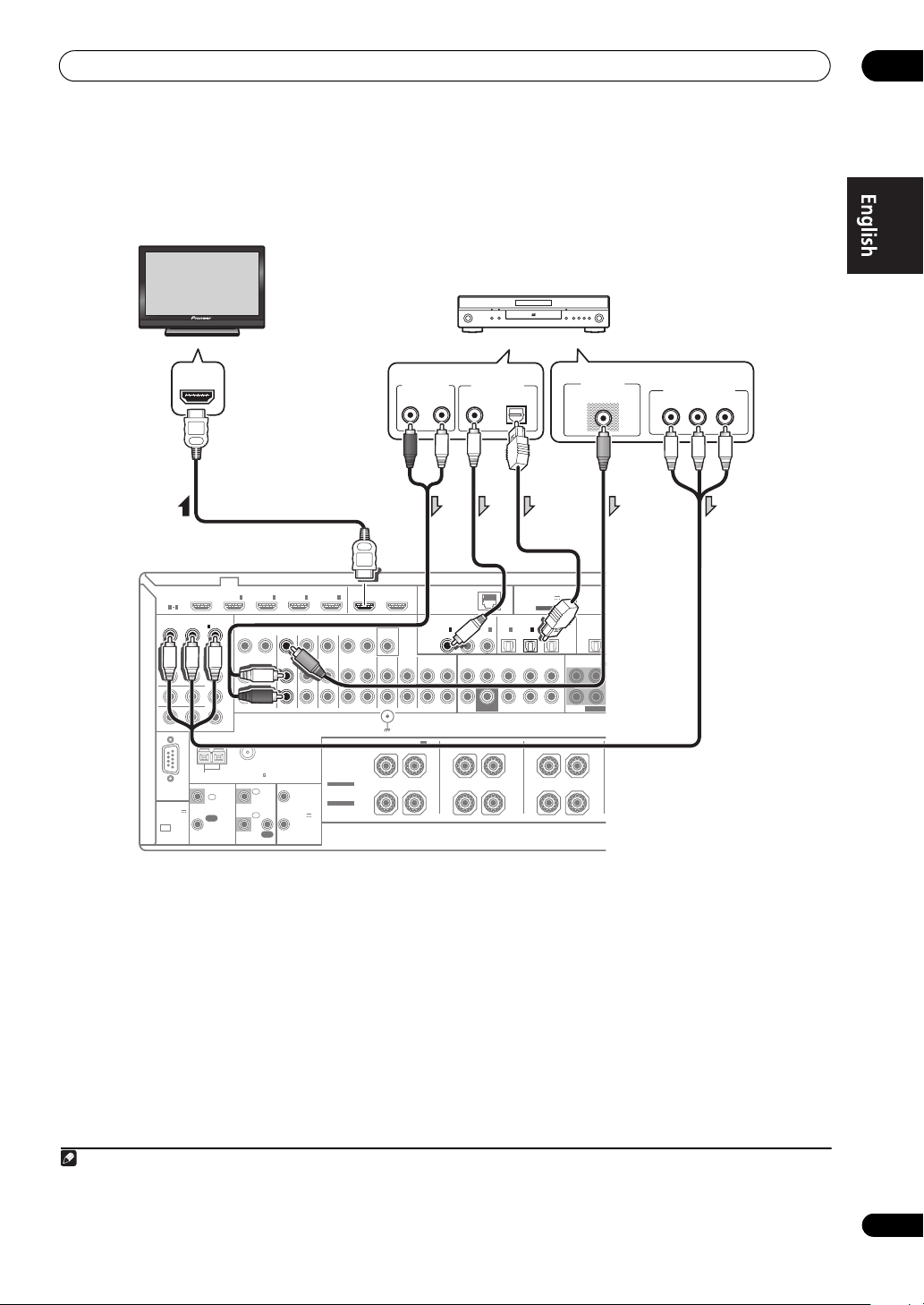
Connecting your TV and playback components
Connecting using HDMI
If you have an HDMI or DVI (with HDCP) equipped component (Blu-ray disc player (BD), etc.), you can connect it to
this receiver using a commercially available HDMI cable.
If the TV and playback components support the Control with HDMI feature, the convenient Control with HDMI
functions can be used (see Control with HDMI function on Operating Instructions in CD-ROM).
HDMI/DVI-compatible
Blu-ray disc player
Other HDMI/DVIequipped component
HDMI
IN
ASSIGNABLE
1 4
COMPONENT VIDEO
ASSIGNABLE
(
)
DVD
1
IN
(
DVR/BDR
2
IN
(
VIDEO
3
IN
MONITOR OUT
ZONE 2 OUT
Y
PRP
B
ANTENNA
CONTROL
RS-232C
IN
(
OUTPUT 5 V
)
150 mA MAX
OUT
CU-RF100
INBD
1IN2IN3
)
ZONE2
ZONE3
OUT
OUT
)
FM UNBAL 75 AM LOOP
IR 12 V
1
IN
2
IN
OUT
HDMI INHDMI OUTHDMI OUT
OUT 1
IN
(
CONTROL
4
MONITOR
DVDINTV/SATINVIDEOINDVR/BDR PHONO
1
2
TRIGGER
(OUTPUT
12 V
TOTAL
150 mA MAX)
OUT IN
SPEAKERS
SELECTABLE
SEE INSTRUCTION
MANUAL
SELECTABLE
VOIR LE MODE
D'EMPLOI
R
Select one
DIGITAL OUT
COAXIAL OPTICAL
OUT 2
(
)
10/100
LAN
)
COAXIAL
IN
(
OUT
IN
FRONT HEIGHT/WIDE/
DVD
VIDEO
CD-R/TAPE
CD
IN
OUT
SIGNAL
GND
B
LR L R L
CAUTION:
SPEAKER IMPEDANCE 6 Ω - 16 Ω .
ATTENTION:
ENCEINTE D'IMPEDANCE DE 6 Ω - 16 Ω .
OPTICAL
1
2
3
IN
IN
)
(CD)
(
)
CD-R
FRONT CENTERSURROUND SURR BACK
IN
SUBWOOFER
SURROUND BACK
(
HDMI/DVI-compatible
monitor
ADAPTER PORT
(
OUTPUT 5 V
)
100 mA MAX
ASSIGNABLEASSIGNABLE
3
1
2
IN
IN
IN
)
(
)
(
)
TV/SAT
DVR/BDR
VIDEO
FH/FW
(Single)
PRE OUT
SURROUND
(Single)
AUDIO OUT
RL
ANALOG
FRONT CE
SUB
This connection is
required in order to
listen to the sound of
the TV over the
1
receiver.
20
En
• When connecting to an HDMI/DVI-compatible
monitor using the HDMI OUT 2 terminal, switch the
HDMI output setting to HDMI OUT 2 or HDMI OUT
ALL. See Switching the HDMI output on Operating
• If you want to listen to the sound of the TV over the
receiver, connect the receiver and TV with audio
1
cables.
Instructions in CD-ROM.
• For input components, connections other than HDMI
connections are also possible (see Connecting your
DVD player with no HDMI output on page 21).
Note
1 When the TV and receiver are connected by HDMI connections, if the TV supports the HDMI Audio Return Channel function, the sound of the
TV is input to the receiver via the HDMI terminal, so there is no need to connect an audio cable. In this case, set TV Audio at HDMI Setup to
via HDMI (see HDMI Setup on Operating Instructions in CD-ROM).
Page 21
Connecting your equipment
R
S
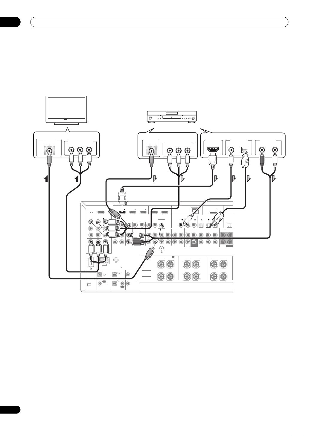
Connecting your DVD player with no HDMI output
This diagram shows connections of a TV (with HDMI input) and DVD player (or other playback component with no
HDMI output) to the receiver.
DVD player, etc.
HDMI/DVI-compatible
monitor
02
HDMI IN
HDMI
ASSIGNABLE
1 4
COMPONENT VIDEO
ASSIGNABLE
Y
RS-232C
(
OUTPUT 5 V
)
150 mA MAX
CU-RF100
IN
IN
IN
B
ANTENNA
IN
(
DVD
1
(
DVR/BDR
2
(
VIDEO
3
MONITOR OUT
ZONE 2 OUT
PRP
CONTROL
IN
OUT
)
INBD
1IN2IN3
)
ZONE2
ZONE3
OUT
OUT
)
FM UNBAL 75 AM LOOP
IR 12 V
IN
1
2
IN
OUT
IN
4
DVDINTV/SATINVIDEOINDVR/BDR PHONO
TRIGGER
1
(OUTPUT
12 V
TOTAL
2
150 mA MAX)
OUT IN
SPEAKERS
SELECTABLE
SEE INSTRUCTION
MANUAL
SELECTABLE
VOIR LE MODE
D'EMPLOI
OUT 1
(
CONTROL
MONITOR
OUT
FRONT HEIGHT/WIDE/
R
AUDIO OUT
R
ANALOG
OUT 2
)
VIDEO
CD
IN
IN
SIGNAL
GND
• If you want to listen to the sound of the TV over the
receiver, connect the receiver and TV with audio
cables (page 20).
1
• If you use an optical digital audio cable, you’ll need to
tell the receiver which digital input you connected the
player to (see The Input Setup menu on Operating
Instructions in CD-ROM).
Select one
DIGITAL OUT
L
COAXIAL OPTICAL
(
)
LAN
10/100
COAXIAL
1
2
IN
IN
(
)
(CD)
DVD
CD-R/TAPE
FRONT CENTERSURROUND SURR BACK
OUT
IN
SURROUND BACK
B
LR L R L
CAUTION:
SPEAKER IMPEDANCE 6 Ω - 16 Ω .
ATTENTION:
ENCEINTE D'IMPEDANCE DE 6 Ω - 16 Ω .
(
CD-R
SUBWOOFER
ADAPTER PORT
(
OUTPUT 5 V
)
100 mA MAX
ASSIGNABLEASSIGNABLE
OPTICAL
3
IN
)
3
1
2
IN
IN
IN
(
)
(
)
(
TV/SAT
)
DVR/BDR
VIDEO
FRONT CENTER
FH/FW
(Single)
PRE OUT
SURROUND
(Single)
VIDEO OUT
VIDEO
OUT
SUBWOOFE
Select one
COMPONENT VIDEO OUT
P
R
P
B
Y
Note
1 When the TV and receiver are connected by HDMI connections, if the TV supports the HDMI Audio Return Channel function, the sound of the
TV is input to the receiver via the HDMI terminal, so there is no need to connect an audio cable. In this case, set TV Audio at HDMI Setup to
via HDMI (see HDMI Setup on Operating Instructions in CD-ROM).
21
En
Page 22
02
R
S
Connecting your equipment
Connecting your TV with no HDMI input
This diagram shows connections of a TV (with no HDMI input) and DVD player (or other playback component) to the
receiver.
• With these connections, the picture is not output to the TV even if the DVD player is connected with an HDMI cable.
Connect the DVD player’s video signals using a composite or component cord.
DVD player, etc.
TV
Select one
VIDEO IN
VIDEO
COMPONENT VIDEO IN
P
R
P
B
Y
HDMI
ASSIGNABLE
1 4
COMPONENT VIDEO
ASSIGNABLE
Y
RS-232C
(
OUTPUT 5 V
)
150 mA MAX
CU-RF100
IN
IN
IN
MONITOR OUT
ZONE 2 OUT
B
ANTENNA
OUT
IN
(
DVD
1
(
DVR/BDR
2
(
VIDEO
3
PRP
CONTROL
IN
)
)
)
INBD
1IN2IN3
ZONE2
ZONE3
DVDINTV/SATINVIDEOINDVR/BDR PHONO
OUT
OUT
FM UNBAL 75 AM LOOP
IR 12 V
1
IN
2
IN
OUT
TRIGGER
1
(OUTPUT
12 V
TOTAL
2
150 mA MAX)
VIDEO OUT
IN
4
OUT IN
SPEAKERS
SELECTABLE
SEE INSTRUCTION
MANUAL
SELECTABLE
VOIR LE MODE
D'EMPLOI
VIDEO
• Connect using an HDMI cable to listen to HD audio
on the receiver. Do not use an HDMI cable to input
video signals.
Depending on the video component, it may not be
possible to output signals connected by HDMI and
other methods simultaneously, and it may be
necessary to make output settings.
operating instructions
supplied with your component
Please refer to the
for more information.
• If you want to listen to the sound of the TV over the
receiver, connect the receiver and TV with audio
cables (page 20).
• If you use an optical digital audio cable, you’ll need to
tell the receiver which digital input you connected the
player to (see The Input Setup menu on Operating
Instructions in CD-ROM).
OUT 1
(
CONTROL
MONITOR
FRONT HEIGHT/WIDE/
R
Select one
COMPONENT VIDEO OUT
P
R
P
B
Y
OUT 2
(
)
LAN
)
OUT
IN
SIGNAL
GND
10/100
COAXIAL
(
VIDEO
CD-R/TAPE
CD
IN
OUT
B
LR L R L
CAUTION:
SPEAKER IMPEDANCE 6 Ω - 16 Ω .
ATTENTION:
ENCEINTE D'IMPEDANCE DE 6 Ω - 16 Ω .
1
2
3
IN
IN
IN
)
(CD)
(
)
DVD
CD-R
FRONT CENTERSURROUND SURR BACK
IN
SUBWOOFER
SURROUND BACK
OPTICAL
IN
(
TV/SAT
1
)
(Single)
HDMI OUT
ADAPTER PORT
(
OUTPUT 5 V
100 mA MAX
ASSIGNABLEASSIGNABLE
2
IN
(
)
(
DVR/BDR
VIDEO
FH/FW
(Single)
PRE OUT
IN
)
3
)
SURROUND
Select one
COAXIAL OPTICAL
OUT
FRONT CENTER
SUBWOOFE
DIGITAL OUT
AUDIO OUT
R
ANALOG
L
22
En
Page 23
Connecting your equipment
R
S
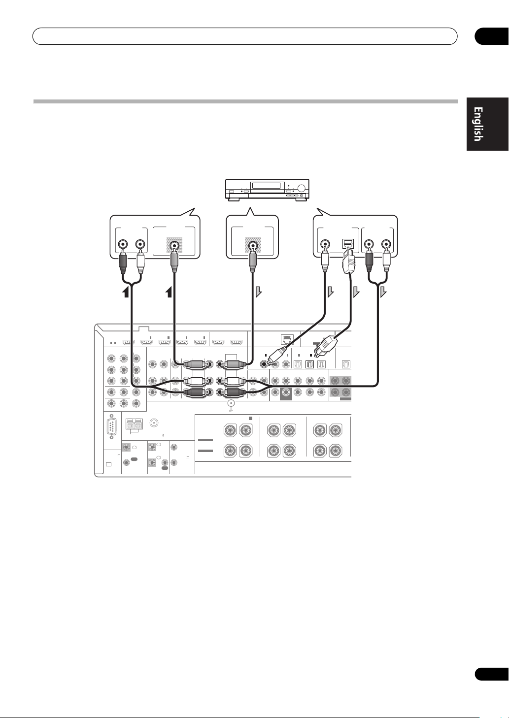
Connecting an HDD/DVD recorder, BD recorder and other video sources
This receiver has two sets of audio/video inputs and outputs suitable for connecting analog or digital video devices,
including HDD/DVD recorders and BD recorders.
When you set up the receiver you’ll need to tell the receiver which input you connected the recorder to (see also The
Input Setup menu on Operating Instructions in CD-ROM).
HDD/DVD recorder, BD recorder, etc.
02
VIDEO IN
INBD
1IN2IN3
)
)
ZONE2
OUT
)
FM UNBAL 75 AM LOOP
IN
IN
VIDEO
ZONE3
DVDINTV/SATINVIDEOINDVR/BDR PHONO
OUT
SPEAKERS
TRIGGER
1
(OUTPUT
12 V
TOTAL
2
150 mA MAX)
SELECTABLE
SEE INSTRUCTION
MANUAL
SELECTABLE
VOIR LE MODE
D'EMPLOI
IR 12 V
1
2
OUT
IN
4
OUT IN
R L
HDMI
ASSIGNABLE
1 4
COMPONENT VIDEO
ASSIGNABLE
Y
RS-232C
(
OUTPUT 5 V
)
150 mA MAX
CU-RF100
ANALOG
IN
IN
IN
B
ANTENNA
IN
(
DVD
1
(
DVR/BDR
2
(
VIDEO
3
MONITOR OUT
ZONE 2 OUT
PRP
CONTROL
IN
OUT
• In order to record, you must connect the analog
audio cables (the digital connection is for playback
only).
• If your HDD/DVD recorder, BD recorder, etc., is
equipped with an HDMI output terminal, we
recommend connecting it to the receiver’s HDMI IN
terminal. When doing so, also connect the receiver
and TV by HDMI (see Connecting using HDMI on
page 20).
OUT 1
(
CONTROL
MONITOR
FRONT HEIGHT/WIDE/
R
VIDEO OUT
VIDEO
OUT 2
(
)
LAN
)
OUT
IN
SIGNAL
GND
10/100
COAXIAL
IN
(
DVD
VIDEO
CD-R/TAPE
CD
IN
IN
OUT
B
LR L R L
CAUTION:
SPEAKER IMPEDANCE 6 Ω - 16 Ω .
ATTENTION:
ENCEINTE D'IMPEDANCE DE 6 Ω - 16 Ω .
OPTICAL
1
2
3
IN
IN
)
(
(CD)
(
)
TV/SAT
CD-R
FRONT CENTERSURROUND SURR BACK
SUBWOOFER
SURROUND BACK
IN
1
)
(Single)
ADAPTER PORT
(
OUTPUT 5 V
100 mA MAX
ASSIGNABLEASSIGNABLE
2
IN
(
)
(
DVR/BDR
FH/FW
(Single)
PRE OUT
Select one
DIGITAL OUT
COAXIAL OPTICAL
)
3
IN
OUT
)
VIDEO
FRONT CENTER
SUBWOOFE
SURROUND
AUDIO OUTAUDIO IN
RL
ANALOG
23
En
Page 24
02
U
Connecting your equipment
Connecting a satellite/cable receiver or other set-top box
Satellite and cable receivers, and terrestrial digital TV tuners are all examples of so-called ‘set-top boxes’.
When you set up the receiver you’ll need to tell the receiver which input you connected the set-top box to (see The Input
Setup menu on Operating Instructions in CD-ROM).
STB
VIDEO OUT
VIDEO
INBD
HDMI
ASSIGNABLE
1 4
COMPONENT VIDEO
ASSIGNABLE
Y
B
ANTENNA
IN
1
IN
2
IN
3
IN
MONITOR OUT
ZONE 2 OUT
PRP
(
DVD
(
DVR/BDR
(
VIDEO
IN2IN
1
)
)
ZONE2
ZONE3
DVDINTV/SATINVIDEOINDVR/BDR PHONO
OUT
OUT
)
IN
3
4
SPEAKERS
RS-232C
(
OUTPUT 5 V
150 mA MAX
CU-RF100
FM UNBAL 75 AM LOOP
CONTROL
IN
)
OUT
1
IN
2
IN
OUT
IR 12 V
TRIGGER
1
(OUTPUT
12 V
TOTAL
2
150 mA MAX)
SELECTABLE
SEE INSTRUCTION
MANUAL
SELECTABLE
VOIR LE MODE
D'EMPLOI
• If your set-top box is equipped with an HDMI output
terminal, we recommend connecting it to the
receiver’s HDMI IN terminal. When doing so, also
connect the receiver and TV by HDMI (see
Connecting using HDMI on page 20).
OUT IN
OUT 1
(
CONTROL
MONITOR
FRONT HEIGHT/WIDE/
R
Select one
AUDIO OUT
R
ANALOG
)
OUT
IN
SIGNAL
GND
OUT 2
VIDEO
DIGITAL OUT
L
COAXIAL OPTICAL
(
)
LAN
10/100
COAXIAL
IN
(
DVD
CD-R/TAPE
CD
IN
OUT
B
LR L R L
CAUTION:
SPEAKER IMPEDANCE 6 Ω - 16 Ω .
ATTENTION:
ENCEINTE D'IMPEDANCE DE 6 Ω - 16 Ω .
OPTICAL
1
2
3
IN
IN
)
(CD)
(
)
CD-R
FRONT CENTERSURROUND SURR BACK
IN
SUBWOOFER
SURROUND BACK
IN
(
TV/SAT
1
)
(Single)
ADAPTER PORT
(
OUTPUT 5 V
100 mA MAX
ASSIGNABLEASSIGNABLE
2
IN
(
)
DVR/BDR
(Single)
PRE OUT
IN
(
VIDEO
FH/FW
)
3
)
SURROUND
FRONT CENTER
SUBWOOFER
OUT
S
24
En
Page 25
Connecting your equipment
Connecting the multichannel analog inputs
For DVD Audio and SACD playback, your DVD player may have 5.1, 6.1 or 7.1 channel analog outputs (depending on
whether your p laye r supports sur roun d back channels). Make sure that the p layer is set to outpu t multichannel analog
audio.
DVD player, etc.
02
IN1IN2IN
ZONE2
ZONE3
DVDINTV/SATINVIDEOINDVR/BDR PHONO
OUT
OUT
FM UNBAL 75
IR 12 V
1
IN
1
2
IN
2
OUT
3
TRIGGER
(OUTPUT
12 V
TOTAL
150 mA MAX)
IN
4
OUT IN
SPEAKERS
SELECTABLE
SEE INSTRUCTION
MANUAL
SELECTABLE
VOIR LE MODE
D'EMPLOI
VIDEO OUT
VIDEO
OUT 1
(
CONTROL
R
)
MONITOR
OUT
VIDEO
IN
SIGNAL
GND
FRONT HEIGHT/WIDE/
SUBWOOFER
OUTPUT
OUT 2
(
10/100
LAN
COAXIAL OPTICAL
1
IN
(
)
DVD
CD-R/TAPE
CD
IN
OUT
IN
B
LR L R L R L
CAUTION:
SPEAKER IMPEDANCE 6 Ω - 16 Ω .
ATTENTION:
ENCEINTE D'IMPEDANCE DE 6 Ω - 16 Ω .
• If there is a single surround back output, connect it to
the SURROUND BACK L jack on this receiver.
• To use a 5.1-channel speaker set, use the surround
speakers for the surround channel, not the surround
back channel.
• The audio signal input to MULTI CH IN cannot be
downmixed.
FRONT
OUTPUT
RL
)
2
IN
(CD)
FRONT CENTER SURROUND SURR BACK
SUBWOOFER
SURROUND BACK
ADAPTER PORT
ASSIGNABLEASSIGNABLE
1
3
IN
IN
IN
(
)
(
(
)
TV/SAT
DVR/BDR
CD-R
(Single)
)
OUT
FRONT CENTER
SUBWOOFER
SURROUND
OUTPUT
RL
SURROUND SURR BACK
MULTI CH IN
CENTER
OUTPUT
(
OUTPUT 5 V
)
100 mA MAX
2
3
IN
)
(
VIDEO
FH/FW
(Single)
PRE OUT
SURROUND FRONT CENTER
SURROUND BACK
OUTPUT
RL
L
R
25
En
Page 26
02
Connecting your equipment
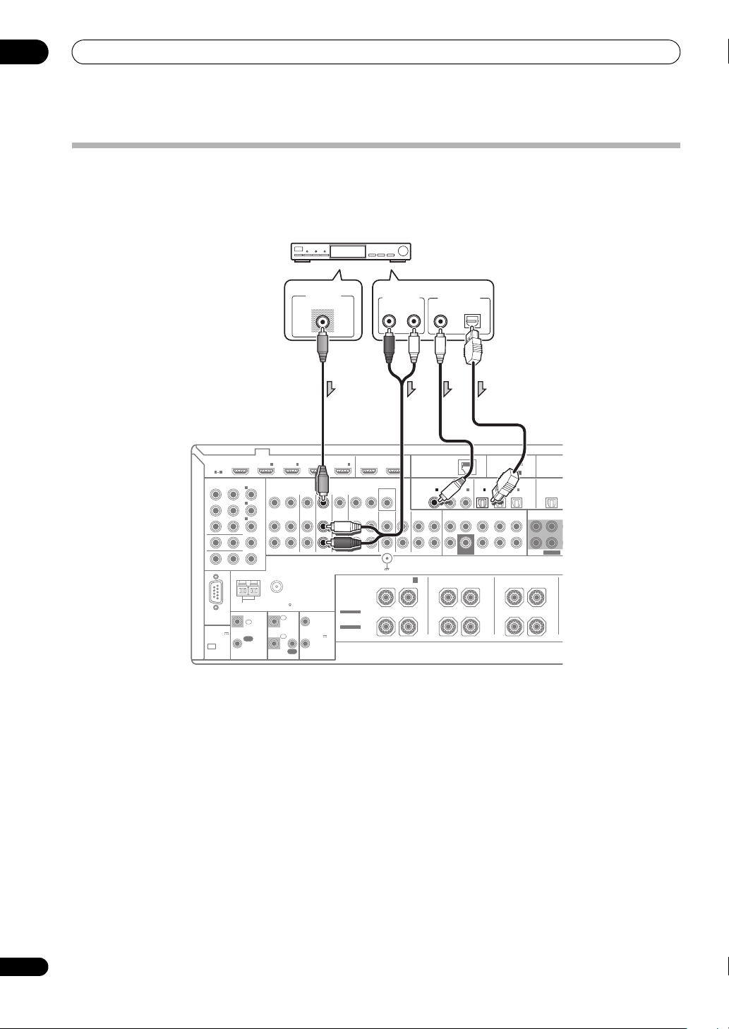
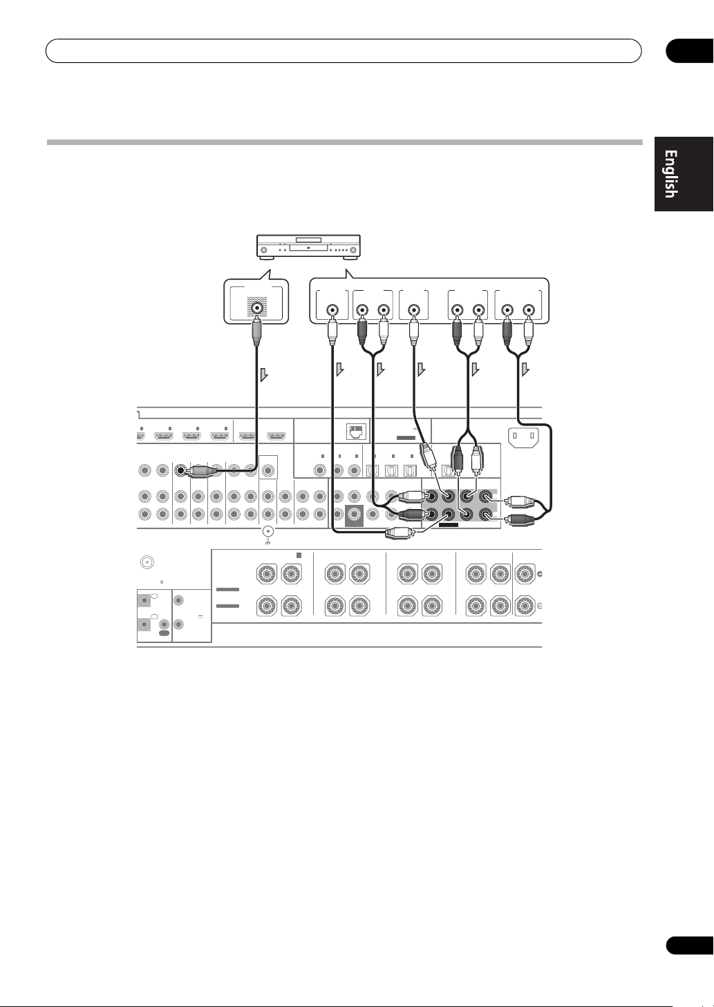
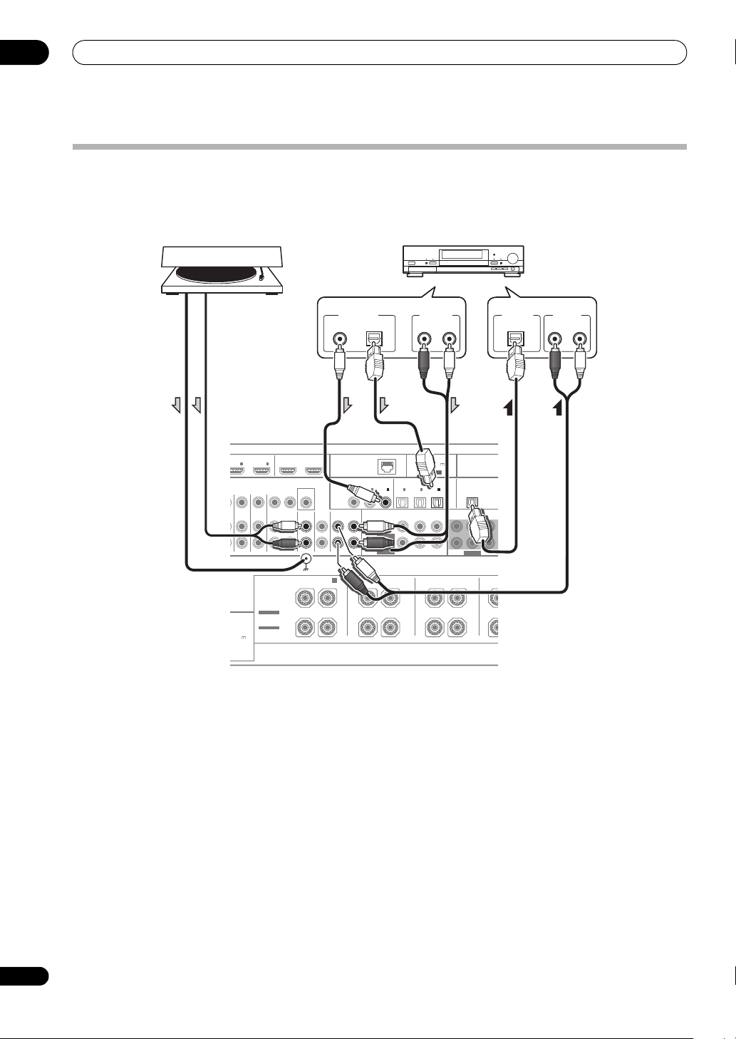
Connecting other audio components
This receiver has both digital and analog inputs, allowing you to connect audio components for playback.
When you set up the receiver you’ll need to tell the receiver which input you connected the component to (see also The
Input Setup menu on Operating Instructions in CD-ROM).
Turntable
CD-R, MD, DAT, etc.
COAXIAL OPTICAL
OUT 1
IN
IN
3
4
TV/SATINVIDEOINDVR/BDR PHONO
OUT IN
SPEAKERS
SELECTABLE
12 V
SEE INSTRUCTION
MANUAL
TRIGGER
SELECTABLE
VOIR LE MODE
(OUTPUT
D'EMPLOI
12 V
TOTAL
150 mA MAX)
(
CONTROL
MONITOR
FRONT HEIGHT/WIDE/
R
OUT 2
)
COAXIAL OPTICAL
OUT
VIDEO
CD-R/TAPE
CD
IN
IN
OUT
SIGNAL
GND
B
LR L R L R
• If you’re connecting a recorder, connect the analog
audio outputs to the analog audio inputs on the
recorder.
• You can’t hear HDMI audio through this receiver’s
digital out jack.
Turntables only:
• If your turntable has a grounding wire, secure it to the
ground terminal on this receiver.
• If your turntable has line-level outputs (i.e., it has a
built-in phono pre-amp), connect it to the CD inputs
instead.
Select one Select one
DIGITAL OUT
(
)
10/100
LAN
1
2
IN
IN
(
)
(CD)
DVD
FRONT CENTERSURROUND SURR BACK
IN
SUBWOOFER
SURROUND BACK
CAUTION:
SPEAKER IMPEDANCE 6 Ω - 16 Ω .
ATTENTION:
ENCEINTE D'IMPEDANCE DE 6 Ω - 16 Ω .
3
IN
(
)
CD-R
AUDIO OUT
RL
ADAPTER PORT
(
OUTPUT 5 V
100 mA MAX
ASSIGNABLEASSIGNABLE
1
2
IN
IN
(
)
(
TV/SAT
DVR/BDR
(Single)
ANALOG
)
(Single)
PRE OUT
(
VIDEO
FH/FW
IN
)
3
)
SURROUND
FRONT CENTER
SUBWOOFER
OUT
SURROUND
DIGITAL IN
OPTICAL
AUDIO IN
RL
ANALOG
26
En
Page 27
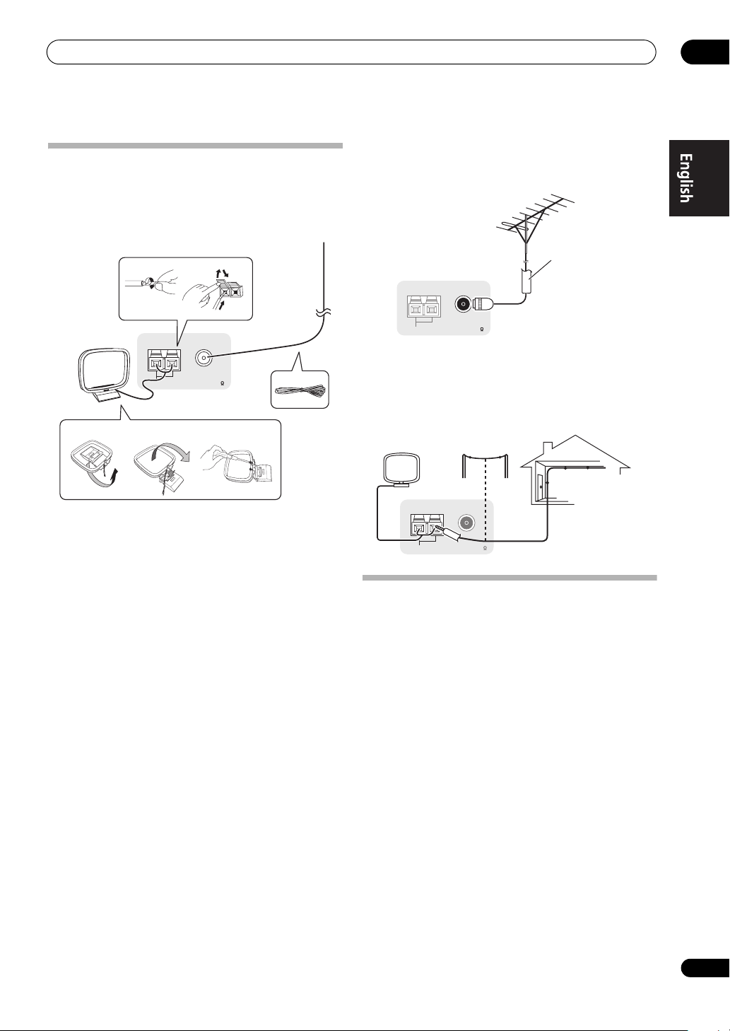
Connecting your equipment
Connecting AM/FM antennas
Connect the AM loop antenna and the FM wire antenna
as shown below. To improve reception and sound quality,
connect external antennas (see Connecting external
antennas below).
1
2
02
Connecting external antennas
To improve FM reception, connect an external FM
antenna to FM UNBAL 75 Ω.
75 Ω coaxial cable
ANTENNA
3
ANTENNA
5
4
fig. a fig. b fig. c
FM UNBAL 75 AM LOOP
1 Pull off the protective shields of both AM antenna
wires.
2 Push open the tabs, then insert one wire fully into
each terminal, then release the tabs to secure the AM
antenna wires.
3 Fix the AM loop antenna to the attached stand.
To fix the stand to the antenna, bend in the direction
indicated by the arrow (fig. a) then clip the loop onto the
stand (fig. b).
• If you plan to mount the AM antenna to a wall or other
surface, secure the stand with screws (fig. c) before
clipping the loop to the stand. Make sure the
reception is clear.
4 Place the AM antenna on a flat surface and in a
direction giving the best reception.
5 Connect the FM wire antenna into the FM antenna
socket.
For best results, extend the FM antenna fully and fix to a
wall or door frame. Don’t drape loosely or leave coiled up.
FM UNBAL 75 AM LOOP
To improve AM reception, connect a 5 m to 6 m length of
vinyl-coated wire to the
AM LOOP
terminals without
disconnecting the supplied AM loop antenna.
For the best possible reception, suspend horizontally
outdoors.
Outdoor antenna
Indoor antenna
(vinyl-coated wire)
ANTENNA
5 m to 6 m
FM UNBAL 75 AM LOOP
MULTI-ZONE setup
This receiver can power up to three independent systems
in separate rooms after you have made the proper MULTIZONE connections.
Different sources can be playing in three zones at the
same time or, depending on your needs, the same source
can also be used. The main and sub zones have
independent power (the main zone power can be off while
one (or both) of the sub zones is on) and the sub zones
can be controlled by the remote or front panel controls.
27
En
Page 28
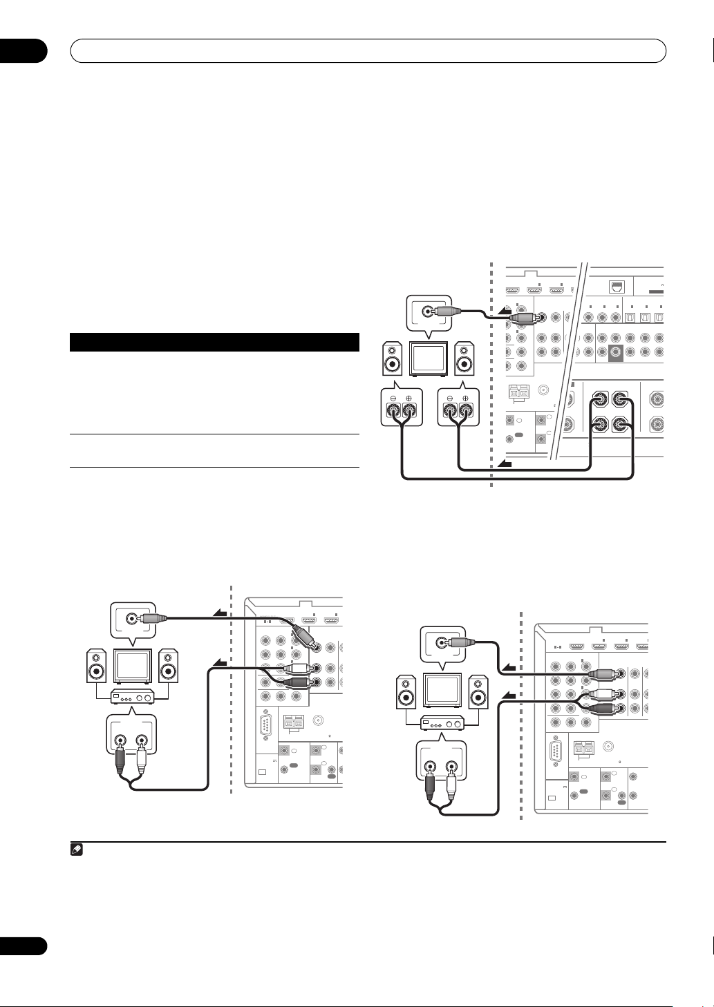
02
D
MONITOR OUT
ZONE 2 OUT
IN
ANTENNA
FM UNBAL 75 AM LOOP
ZONE2
OUT
ZONE3
OUT
DVD
IN
P
R
B
1
INBD
IN
1IN2
(
DVD
)
IN
2
(
DVR/BDR
)
IN
3
(
VIDEO
)
CONTROL IR 1
T
IN
IN
IN
OUT
OUT
1
2
1
2
(
1
T
1
COAXIAL OPTICAL
ASSIGNABLEASSIGNABLE
CD-R/TAPE
IN
CD
IN
DEO
OUT
IN
1
(
DVD
)
IN
1
(
TV/SAT
)
IN
2
(
DVR/BDR
)
IN
FRONT CENTER SURROUND SURR BACK
(Single)
FH/FW
3
(
VIDEO
)
IN
2
(CD)
IN
3
(
CD-R
)
SUBWOOFER
LAN
(
10/100
)
(
OUTPUT 5 V
100 mA MAX
)
ADAPTER POR
PRE OU
CAUTION:
SPEAKER IMPEDANCE 6 Ω - 16 Ω .
ATTENTION:
ENCEINTE D'IMPEDANCE DE 6 Ω - 16 Ω .
SURROUND BACK
(Single)
B
L RLR
SU
/
N
3
G
T
A
m
Connecting your equipment
28
En
Making MULTI-ZONE connections
It is possible to make these connections if you have a
separate TV and speakers for your primary (ZONE 2) sub
zone, and a separate TV and a separate amplifier (and
speakers) for your secondary (ZONE 3) sub zone. You will
also need a separate amplifier if you are not using the
MULTI-ZONE setup using speaker terminals (ZONE 2)
below for your primary sub zone. There are two primary
sub zone setups possible with this system. Choose
MULTI-ZONE setup using speaker terminals (ZONE 2)
You must select ZONE 2 in Speaker system setting on
page 111 to use this setup.
• Connect a TV monitor to the
jacks on this receiver.
2
VIDEO ZONE 2 OUT
You should have a pair of speakers attached to the
surround back speaker terminals as shown below.
Sub zone (ZONE 2)
Main zone
whichever works best for you.
MULTI-ZONE listening options
The following table shows the signals that can be output
1
to ZONE 2 and ZONE 3
:
VIDEO IN
Sub Zone Input functions available
ZONE 2 DVD, TV/SAT, DVR/BDR, VIDEO, HOME MEDIA
GALLERY (SC-LX83 only), INTERNET RADIO (SCLX73 only), iPod/USB, CD, CD-R/TAPE, TUNER,
ADAPTER PORT
RL
(Outputs analog audio, composite video and
component video (SC-LX83 only).)
ZONE 3 Same as ZONE 2 above.
(Outputs analog audio and composite video.)
Basic MULTI-ZONE setup (ZONE 2)
• Connect a separate amplifier to the
jacks and a TV monitor to the
OUT
jack, both on this receiver.
You should have a pair of speakers attached to the sub
zone amplifier as shown in the following illustration.
VIDEO IN
AUDIO IN
RL
Note
1 For the INTERNET RADIO (SC-LX73 only), HOME MEDIA GALLERY (SC-LX83 only) and iPod/USB inputs, it is not possible use the same input
in ZONE 2 and ZONE 3 simultaneously.
2 SC-LX83 only:
• COMPONENT VIDEO ZONE 2 OUT can be used to output clear images.
• The GUI screen is not displayed if only the COMPONENT VIDEO ZONE 2 OUT jack is connected.
• The video convert function does not work for ZONE 2. Connect the composite video and component video to the same types of jacks for the
inputs and outputs.
AUDIO ZONE 2
VIDEO ZONE 2 OUT2
Main zoneSub zone (ZONE 2)
ASSIGNABLE
)
IN
IN
IN
B
ANTENNA
IN
(
DVD
1
(
DVR/BDR
2
(
VIDEO
3
MONITOR OUT
ZONE 2 OUT
PRP
CONTROL
IN
OUT
)
)
INBD
1IN2
)
ZONE2
OUT
FM UNBAL 75 AM LOOP
ZONE3
OUT
IR
1
IN
2
IN
OUT
HDMI
ASSIGNABLE
1 4
COMPONENT VIDEO
Y
RS-232C
(
OUTPUT 5 V
150 mA MAX
CU-RF100
Secondary MULTI-ZONE setup (ZONE 3)
• Connect a separate amplifier to the
OUT
jacks and a TV monitor to the
AUDIO ZONE 3
VIDEO ZONE 3 OUT
jack, both on this receiver.
You should have a pair of speakers attached to the sub
zone amplifier as shown in the following illustration.
Sub zone (ZONE 3)
VIDEO IN
AUDIO IN
RL
Main zone
HDMI
ASSIGNABLE
1 4
COMPONENT VIDEO
ASSIGNABLE
Y
RS-232C
(
OUTPUT 5 V
)
150 mA MAX
CU-RF100
IN
IN
IN
B
ANTENNA
IN
(
DVD
1
(
DVR/BDR
2
(
VIDEO
3
MONITOR OUT
ZONE 2 OUT
PRP
CONTROL
IN
OUT
)
)
INBD
1IN2
)
ZONE2
OUT
FM UNBAL 75 AM LOOP
ZONE3
1
IN
2
IN
OUT
IR 12 V
OUT
DVDINTV
I
I
TRI
1
(OU
12 V
TOT
2
150
Page 29
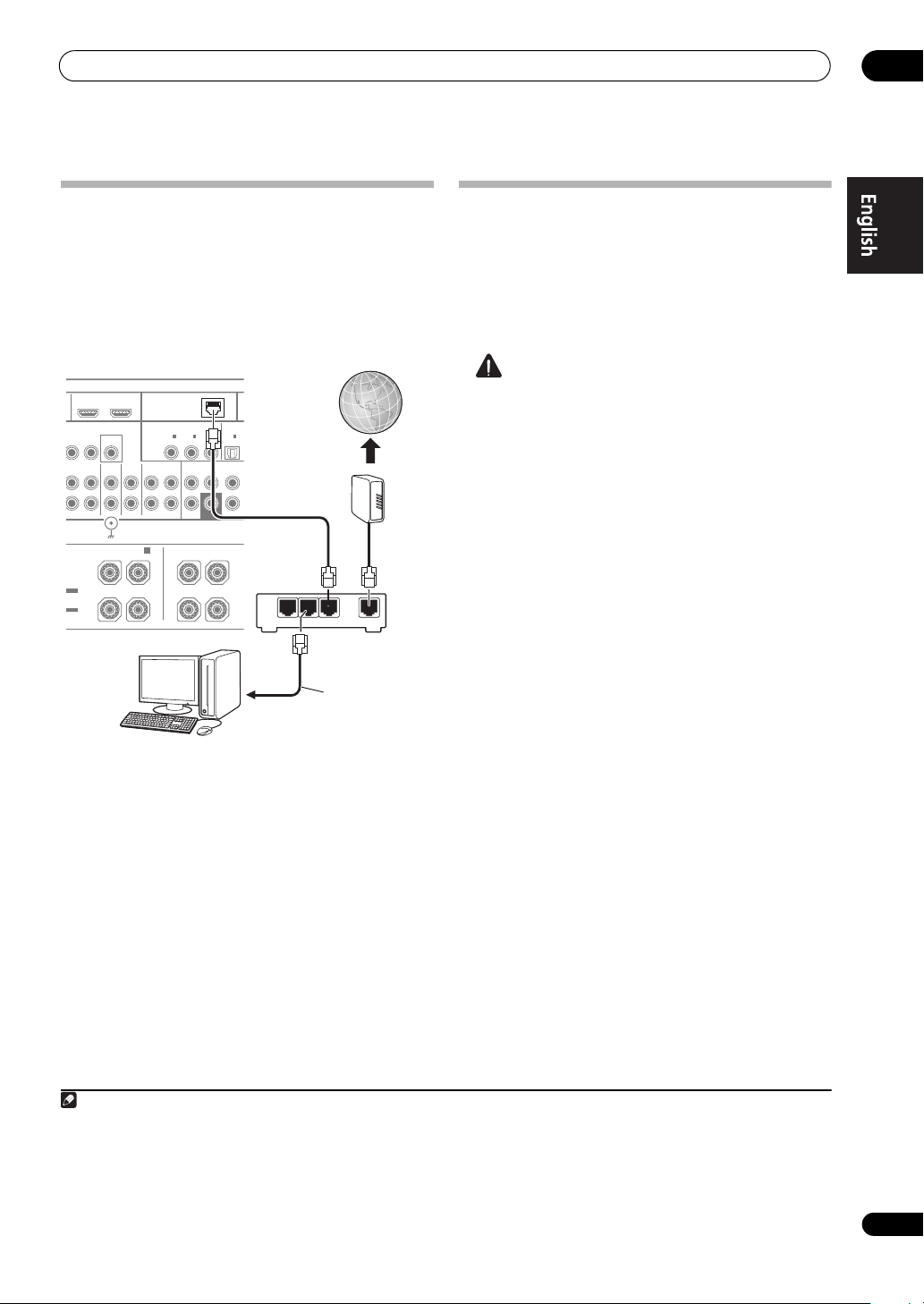
Connecting your equipment
L
e
T
02
Connecting to the network through LAN interface
By connecting this receiver to the network via the LAN
terminal, you can listen to Internet radio stations.
SC-LX83 only: When connected in this way, you can play
audio files stored on the components on the network,
including your computer, using HOME MEDIA GALLERY
2
inputs.
OUT 1
OUT 2
(
)
LAN
COAXIAL OPTICA
(
VIDEO
CD-R/TAPE
CD
IN
OUT
10/100
ASSIGNABLE
1
2
IN
IN
)
(CD)
DVD
FRONT CENTERSURROUND
IN
1
3
IN
IN
(
)
(
)
TV/SAT
CD-R
Internet
(
CONTROL
DVR/BDR PHONO
OUT IN
MONITOR
)
OUT
IN
Modem
SUBWOOFER
SURROUND BACK
LR L
(Singl
LAN
321
ERS
ABLE
RUCTION
ABLE
MODE
I
SIGNAL
FRONT HEIGHT/WIDE/
R
GND
B
Router
(sold separately)
to LAN port
PC
Connect the LAN terminal on this receiver to the LAN
terminal on your router (with or without the built-in DHCP
server function) with a straight LAN cable (CAT 5 or
higher).
Turn on the DHCP server function of your router. In case
your router does not have the built-in DHCP server
function, it is necessary to set up the network manually.
For details, see Network Setup menu on page 113.
1
WAN
LAN cable
Plugging in the receiver
Only plug in after you have connected all your
components to this receiver, including the speakers.
1 Plug the supplied power cord into the
on the back of the receiver.
2 Plug the other end into a power outlet.
CAUTION
• Handle the power cord by the plug part. Do not pull
out the plug by tugging the cord, and never touch the
power cord when your hands are wet, as this could
cause a short circuit or electric shock. Do not place
the unit, a piece of furniture, or other object on the
power cord or pinch the cord in any other way. Never
make a knot in the cord or tie it with other cables. The
power cords should be routed so that they are not
likely to be stepped on. A damaged power cord can
cause a fire or give you an electric shock. Check the
power cord once in a while. If you find it damaged,
ask your nearest Pioneer authorized independent
service company for a replacement.
• Do not use any power cord other than the one
supplied with this unit.
• Do not use the supplied power cord for any purpose
other than that described below.
• The receiver should be disconnected by removing the
mains plug from the wall socket when not in regular
use, e.g., when on vacation.
•Make sure the blue STANDBY/ON light has gone
out before unplugging.
• If you have connected speakers with a 6
impedance, change the impedance setting before
turning on the power.
AC IN
3
Ω
socket
LAN terminal specifications
LAN terminal . . . . . . . . . . . . . . . . . . . . . . . . . . . . Ethernet jack
10BASE-T/100BASE-TX
Note
1 To listen to Internet radio stations, you must sign a contract with an ISP (Internet Service Provider) beforehand.
2 • Photo or video files cannot be played back.
• With Windows Media Player 11 or Windows Media Player 12, you can even play back copyrighted audio files on this receiver.
3 After this receiver is connected to an AC outlet, a 2 second to 10 second HDMI initialization process begins. You cannot carry out any
operations during this process. The HDMI indicator in the front panel display blinks during this process, and you can turn on this receiver
once it has stopped blinking. When you set the Control with HDMI to OFF, you can skip this process. For details about the Control with HDMI
feature, see Control with HDMI function on Operating Instructions in CD-ROM.
29
En
Page 30
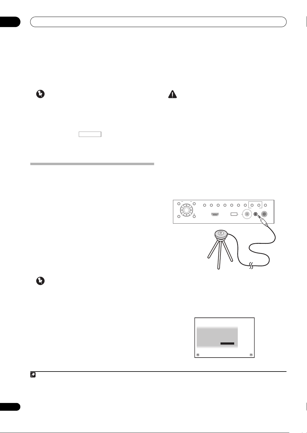
03
Basic Setup
Chapter 3:
Basic Setup
Important
• The procedure for setting the receiver operation
mode differs for the remote controls included with
the SC-LX83 and SC-LX73. For the SC-LX83’s remote
control, set the remote control operation selector
switch to RECEIVER. For the SC-LX73’s remote
control, press the button. When “set the
RECEIVER
remote control to the receiver operation mode” is
indicated in these instructions, use the respective
procedure described above.
Automatically conducting optimum sound tuning (Full Auto MCACC)
The Full Auto MCACC Setup measures the acoustic
characteristics of your listening area, taking into account
ambient noise, speaker connection and speaker size, and
tests for both channel delay and channel level. After you
have set up the microphone provided with your system,
the receiver uses the information from a series of test
tones to optimize the speaker settings and equalization
for your particular room.
SC-LX83 only: By performing the Full Auto MCACC Setup
procedure, the frequency-phase characteristics of the
connected speakers are also calibrated.
Once the Full Auto MCACC Setup procedure is
completed, the Full Band Phase Control function is
automatically turned on.
Important
• Make sure the microphone and speakers are not
moved during the Full Auto MCACC Setup.
• Using the Full Auto MCACC Setup will overwrite any
existing settings for the MCACC preset you select.
• Before using the Full Auto MCACC Setup, the
headphones should be disconnected.
CAUTION
• The test tones used in the Full Auto MCACC Setup
are output at high volume.
®
THX
• THX is a trademark of THX Ltd., which may be
registered in some jurisdictions. All rights reserved.
1 Switch on the receiver and your TV.
Make sure that the TV’s video input is set to this receiver.
2 Connect the microphone to the
MCACC SETUP MIC
jack on the front panel.
• Push down on the lower portion of the front panel
door to access the MCACC SETUP MIC jack.
Make sure there are no obstacles between the speakers
and the microphone.
AUDIO VIDEO
PARAMETER
(TUNE)
ENTER
(TUNE)
HOME MENU RETURN
TUNER EDIT
AUTO SURR/ALC/
HOME
STANDARD
STREAM DIRECT
THX
(PRESET)(PRESET)
VIDEO CAMERA
SURROUND
CONTROL
ADVANCED
SURROUND
iPhone
USBHDMI 5
ON/OFF
STEREOBAND
iPod
MULTI-ZONE
MCACC
SETUP MIC
SPEAKERS
PHONES
Microphone
Tripod
If you have a tripod, use it to place the microphone so that
it’s about ear level at your normal listening position. If you
do not have a tripod, use some other object to install the
microphone.
The Full Auto MCACC display appears once the
microphone is connected.
1
1a.Full Auto MCACC
Speaker System : Normal(SB/FH
EQ Type : SYMMETRY
MCACC : M1.MEMORY 1
THX Speaker : NO
START
2
A/V RECEIVER
)
30
En
Exit Return
Note
1 Install the microphone on a stable floor. Placing the microphone on any of the following surfaces may make accurate measurement
impossible:
• Sofas or other soft surfaces.
• High places such as tabletops and sofa tops.
2 If you leave the GUI screen for over five minutes, the screen saver will appear.
Page 31

Basic Setup
03
3 Select the parameters you want to set.
1
If the speakers are connected using any setup other than
Normal(SB/FH), be sure to set Speaker System before
the Full Auto MCACC Setup. See Speaker system setting
on Operating Instructions in CD-ROM.
2
• Speaker System
– Shows the current settings.
When this is selected and ENTER is pressed, the
speaker system selection screen appears. Select the
proper speaker system, then press RETURN to return.
• EQ Type – This determines how the frequency
balance is adjusted.
• MCACC – The six MCACC presets are used for storing
surround sound settings for different listening
positions. Simply choose an unused preset for now.
• THX Speaker – Select YES if you are using THX
speakers (set all speakers to SMALL), otherwise leave
it set to NO.
4 Set the remote control to the receiver operation
mode, then select
START
.
5 Follow the instructions on-screen.
Make sure the microphone is connected, and if you’re
using a subwoofer, make sure it is switched on and set to
a comfortable volume level.
6 Wait for the test tones to finish, then confirm the
speaker configuration in the GUI screen.
A progress report is displayed on-screen while the
receiver outputs test tones to determine the speakers
present in your setup. Try to be as quiet as possible while
it’s doing this.
If no operations are performed for 10 seconds while the
speaker configuration check screen is being displayed,
the Full Auto MCACC Setup will resume automatically. In
this case, you don’t need to select ‘OK’ and press ENTER
in step 7.
• With error messages (such as Too much ambient
noise! or Check microphone.), select RETRY after
checking for ambient noise (see Problems when
using the Auto MCACC Setup on page 32) and
verifying the mic connection. If there doesn’t seem to
be a problem, you can simply select GO NEXT and
continue.
1a.Full Auto MCACC
Now Analyzing... 2/10
Environment Check
Exit Cancel
A/V RECEIVER
Ambient Noise : OK
Microphone :
Speaker YES/NO :
1a.Full Auto MCACC
L : YES
FHL : YES
C : YES
FHR : YES
R : YES
SR : YES
SBR : YES
SBL : YES
SL : YES
SW : YES
10
Exit Cancel
A/V RECEIVER
OK RETRY
The configuration shown on-screen should reflect the
actual speakers you have.
• If you see an ERR message (or the speaker
configuration displayed isn’t correct), there may be a
problem with the speaker connection.
If selecting RETRY doesn’t work, turn off the power
and check the speaker connections. If there doesn’t
seem to be a problem, you can simply use / to
select the speaker and / to change the setting
and continue.
•If Reverse Phase is displayed, the speaker’s wiring
(+ and –) may be inverted. Check the speaker
connections.
3
– If the connections were wrong, turn off the power,
disconnect the power cord, then reconnect properly.
After this, perform the Full Auto MCACC procedure
again.
– If the connections were right, select GO NEXT and
continue.
7 Make sure ‘OK’ is selected, then press
A progress report is displayed on-screen while the
receiver outputs more test tones to determine the
optimum receiver settings.
Again, try to be as quiet as possible while this is
happening. It may take 3 to 10 minutes.
ENTER
.
Note
1 • When data measurement is taken, the reverb characteristics data (both before- and after-calibration) that this receiver had been storing will
be overwritten. If you want to save the reverb characteristics data before measuring, connect a USB memory device to this receiver and
transfer the data.
• When measurement is taken of the reverb characteristics data other than SYMMETRY, the data are not measured after the correction. If
you will need to measure after correcting data, take the measurement using the EQ Professional menu in the Manual MCACC setup.
2 If you are planning on bi-amping your front speakers, or setting up a separate speaker system in another room, read through Speaker system
setting on Operating Instructions in CD-ROM and make sure to connect your speakers as necessary before continuing to step 4.
3 If the speaker is not pointed to the microphone (listening position) or when using speakers that affect the phase (dipole speakers, reflective
speakers, etc.), Reverse Phase may be displayed even if the speakers are properly connected.
31
En
Page 32

03
Basic Setup
8 The Full Auto MCACC Setup procedure is completed
and the
Be sure to disconnect the microphone from this receiver
upon completion of the Full Auto MCACC Setup.
Problems when using the Auto MCACC Setup
If the room environment is not optimal for the Auto
MCACC Setup (too much background noise, echo off the
walls, obstacles blocking the speakers from the
microphone) the final settings may be incorrect. Check
for household appliances (air conditioner, fridge, fan,
etc.), that may be affecting the environment and switch
them off if necessary. If there are any instructions
showing in the front panel display, please follow them.
Home Menu
menu reappears automatically.
1
• Some older TVs may interfere with the operation of
the microphone. If this seems to be happening,
switch off the TV when doing the Auto MCACC Setup.
32
En
Note
1 • Depending on the characteristics of your room, sometimes identical speakers with cone sizes of around 12 cm will end up with different size
settings. You can correct the setting manually using the Manual speaker setup on Operating Instructions in CD-ROM.
• The subwoofer distance setting may be farther than the actual distance from the listening position. This setting should be accurate (taking
delay and room characteristics into account) and generally does not need to be changed.
• If Full Auto MCACC Setup measurement results are incorrect due to the interaction of the speakers and viewing environment, we
recommend adjusting the settings manually.
Page 33

Basic playback
Chapter 4:
Basic playback
04
Important
• The procedure for setting the receiver operation
mode differs for the remote controls included with
the SC-LX83 and SC-LX73. For the SC-LX83’s remote
control, set the remote control operation selector
switch to RECEIVER. For the SC-LX73’s remote
control, press the button. When “set the
remote control to the receiver operation mode” is
indicated in these instructions, use the respective
procedure described above.
RECEIVER
Playing a source
Here are the basic instructions for playing a source (such
as a DVD disc) with your home theater system.
1 Switch on your system components and receiver.
Make sure that the TV’s video input is set to this receiver.
2 Set the remote control to the receiver operation
mode.
3 Select the input function you want to play.
You can use the input function buttons on the remote
control, INPUT SELECT, or the front panel INPUT
SELECTOR dial.
4Press
SURROUND
If you’re playing a Dolby Digital or DTS surround sound
source, you should hear surround sound. If you are
playing a stereo source, you will only hear sound from the
front left/right speakers in the default listening mode.
5 Use the volume control to adjust the volume level.
1
AUTO/ALC/DIRECT
’ and start playback of the source.
to select ‘
AUTO
2
Listening in surround sound
Using this receiver, you can listen to any source in
surround sound.
Standard surround sound
The following modes provide basic surround sound for
stereo and multichannel sources.
• While listening to a source, set the remote control
to the receiver operation mode, then press
If necessary, press repeatedly to select a listening mode.
The listening modes that can be selected depend on the
input signals and settings.
With two channel sources, you can select from:
• 2 Pro Logic IIx MOVIE
• 2 Pro Logic IIx MUSIC
• 2 Pro Logic IIx GAME
• 2 PRO LOGIC – Suitable for old movie
• 2 Pro Logic IIz HEIGHT – Suitable for Front height
system
• WIDE SURROUND MOVIE – Suitable for Front wide
system
• WIDE SURROUND MUSIC – Suitable for Front wide
system
• Neo:6 CINEMA
• Neo:6 MUSIC
• Neural Surround – Suitable for music sources
With multichannel sources, you can select from:
• 2 Pro Logic IIx MOVIE
• 2 Pro Logic IIx MUSIC
• Dolby Digital EX – Suitable for movie and music
sources
• DTS-ES – Suitable for movie and music sources
• DTS Neo:6 – Suitable for movie and music sources
• 2 Pro Logic IIz HEIGHT – See above
• WIDE SURROUND MOVIE – See above
• WIDE SURROUND MUSIC – See above
• Straight Decode – Plays back without the effects
above.
STANDARD
.
Note
1 If you need to manually switch the input signal type press SIGNAL SEL.
2 You may need to check the digital audio output settings on your DVD player or digital satellite receiver. It should be set to output Dolby Digital,
DTS and 88.2 kHz / 96 kHz PCM (2 channel) audio, and if there is an MPEG audio option, set this to convert the MPEG audio to PCM.
33
En
Page 34

04
Basic playback
Using the Home THX modes
THX and Home THX are technical standards created by
THX Ltd. for cinema and home theater sound. Home THX
is designed to make home theater audio sound more like
what you hear in a cinema.
• Set the remote control to the receiver operation
mode, then press
The listening modes that can be selected depend on the
input signals and settings.
With two channel sources, press THX repeatedly to select
from:
• THX CINEMA
• THX MUSIC
• THX GAMES
• 2 Pro Logic IIx MOVIE+THX CINEMA
• 2 PRO LOGIC+THX CINEMA
• Neo:6 CINEMA+THX CINEMA
• 2 Pro Logic IIx MUSIC+THX MUSIC
• Neo:6 MUSIC+THX MUSIC
• 2 Pro Logic IIx GAME+THX GAMES
• 2 Pro Logic IIz HEIGHT+THX CINEMA
• 2 Pro Logic IIz HEIGHT+THX MUSIC
• 2 Pro Logic IIz HEIGHT+THX GAMES
• THX ULTRA2/SELECT2 GAMES
With multichannel sources, press THX repeatedly to
select from:
• THX CINEMA
• THX MUSIC
• THX GAMES
• THX Surround EX
• Neo:6 CINEMA+THX CINEMA
• 2 Pro Logic IIx MOVIE+THX CINEMA
• THX ULTRA2/SELECT2 CINEMA
• 2 Pro Logic IIx MUSIC+THX MUSIC
• 2 Pro Logic IIz HEIGHT+THX CINEMA
• 2 Pro Logic IIz HEIGHT+THX MUSIC
• 2 Pro Logic IIz HEIGHT+THX GAMES
•
THX ULTRA2/SELECT2 MUSIC
• THX ULTRA2/SELECT2 GAMES
THX
to select a listening mode.
1
1
1
1
Using the Advanced surround effects
The Advanced surround effects can be used for a variety
of additional surround sound effects.
• Set the remote control to the receiver operation
mode, then press
listening mode.
• ACTION
• DRAMA
• SCI-FI – Designed for science fiction with lots of
special effects
• MONO FILM
• ENT.SHOW – Suitable for musical sources
• EXPANDED – Creates an extra wide stereo field
• TV SURROUND
• ADVANCED GAME
• SPORTS
• CLASSICAL
• ROCK/POP
• UNPLUGGED – Suitable for acoustic music sources
• EXT.STEREO – Gives multichannel sound to a stereo
source, using all of your speakers
• PHONES SURR – When listening through
headphones.
ADV SURR
repeatedly to select a
Using Auto surround, ALC, Optimum surround and Stream Direct modes
• While listening to a source, set the remote control
to the receiver operation mode, then press
DIRECT
to select the mode you want.
• AUTO SURROUND – The receiver automatically
detects what kind of source you’re playing and
selects multichannel or stereo playback as
necessary.
• ALC – The receiver equalizes playback sound levels.
• OPTIMUM SURR (SC-LX83 only) – In the Optimum
Surround mode, this receiver automatically
optimizes sound balance in each scene based on
actually set volume. The sound balancer controls
three major theater sound elements dialogue, bass
and surround with original algorithm.
• DIRECT – Plays back sound from source with the
least modification next to PURE DIRECT. With
DIRECT, the only modifications added to PURE
DIRECT playback are calibration of the sound field by
the MCACC system and the Phase Control effect.
• PURE DIRECT – Plays back unmodified sound from
source with only minimal digital treatment. No sound
is output from the Speaker B in this mode.
AUTO/ALC/
34
En
Note
1• ULTRA2 for the SC-LX83, SELECT2 for the SC-LX73.
Page 35

Basic playback
Playing an iPod
This receiver has the iPod/iPhone/USB terminal that will
allow you to control playback of audio content from your
iPod using the controls of this receiver.
1 Switch the receiver into standby then use the
supplied iPod cable to connect your iPod to the
iPhone/USB
terminal on the front panel of this
receiver.
TUNER EDIT
AUTO SURR/ALC/
HOME
STANDARD
STREAM DIRECT
HDMI 5
VIDEO CAMERA
iPod cable
(supplied)
ADVANCED
THX
SURROUND
SURROUND
iPod
iPhone
USB
1
iPod/
CONTROL
ON/OFF
STEREOBAND
MULTI-ZONE
MCACC
SETUP MIC
SPEAKERS
PHONES
MENU
iPod
Basic playback controls
SC-LX83:
• Set the remote control operation selector switch to
SOURCE, then press iPod USB to switch the remote
control to the iPod/USB operation mode.
SOURCE
RECEIVER
TV
CH
VOL
VOL
TV CONTROL
INPUT MUTE
AUDIO
PARAMETER
LIST
TOP MENU
BAND
PRESET PRESET
CATEGORY
HOME
MENU
iPod CTRL PTY SEARCH
TUNE
ENTER
TUNE
TOOLS
MUTE
VIDEO
PARAMETER
T.EDIT
GUIDE
RETURN
STATUS
PHASE CTRL CH LEVEL
THX PQLSMPX MEMORY
AUTO/ALC/
STANDARD ADV SURR
DIRECT
STEREO
PGM MENU
SIGNAL SEL SLEEP AUDIO
DIMMER
A.ATT
SBch MCACC
HDMI OUT
D.ACCESS
CLASS
ENTER
CLR
INFO
DISP
CH
SC-LX73:
• Press iPod USB to switch the remote control to the
iPod/USB operation mode.
STEREO
DIRECT
STANDARD
TUNE
ENTER
TUNE
TOOLS
VIDEO
PARAMETER
T.EDIT
RETURN
AUDIO
PARAMETER
LIST
TOP MENU
BAND GUIDE
PRESET
PTY
SEARCH
HOME
MENU
iPod CTRL
PRESET
HDD DVD
/
DTV MPX PQLS
TV
HDMI OUT
SIGNAL SEL
MCACC SLEEP
ADV SURR
CTRL STATUSTHX
PHASE
AUDIO
213
INFO
DISP
546
04
2 Switch on the receiver and your TV.
3Press
receiver to the
4Use
5Use
played, then press the
1 • This system is compatible with the audio and video of the iPod nano (audio only for the iPod nano 1G), iPod fifth generation (audio only),
iPod USB
/
/
on the remote control to switch the
iPod/USB
.
to select ‘Music’ from the iPod top menu.
and ENTER to select the track to be
PLAY
button.
Note
iPod classic, iPod touch and iPhone. However, some of the functions may be restricted for some models. The system is not compatible with
the iPod shuffle.
•
Compatibility may vary depending on the software version of your iPod and iPhone. Please be sure to use the latest available software
version.
• iPod and iPhone are licensed for reproduction of non-copyrighted materials or materials the user is legally permitted to reproduce.
• Features such as the equalizer cannot be controlled using this receiver, and we recommend switching the equalizer off before connecting.
• Pioneer cannot under any circumstances accept responsibility for any direct or indirect loss arising from any inconvenience or loss of
recorded material resulting from the iPod failure.
• When listening to a track on the iPod in the main zone, it is possible to control the sub zone, but not to listen to a different track in the sub
zone from the one playing in the main zone.
35
En
Page 36

04
Basic playback
Playing a USB device
It is possible to play files1 using the USB interface on the
front of this receiver.
1 Switch the receiver into standby then connect your
USB device to the USB terminal on the front panel of
this receiver.
CONTROL
ON/OFF
SPEAKERS
TUNER EDIT
AUTO SURR/ALC/
HOME
STANDARD
STREAM DIRECT
VIDEO CAMERA
ADVANCED
THX
SURROUND
SURROUND
USBHDMI 5
2 Switch on the receiver and your TV.
3Press
receiver to the
4Use
5Use
played, then press the
iPod USB
/
/
on the remote control to switch the
iPod/USB
3
.
to select ‘Music’ from the
and ENTER to select the track to be
PLAY
Basic playback controls
SC-LX83:
• Set the remote control operation selector switch to
SOURCE, then press iPod USB to switch the remote
control to the iPod/USB operation mode.
SOURCE
RECEIVER
TV
CH
VOL
VOL
TV CONTROL
INPUT MUTE
AUDIO
PARAMETER
LIST
TOP MENU
BAND
PRESET PRESET
CATEGORY
HOME
MENU
iPod CTRL PTY SEARCH
TUNE
ENTER
TUNE
TOOLS
MUTE
VIDEO
PARAMETER
T.EDIT
GUIDE
RETURN
MULTI-ZONE
STEREOBAND
iPod
iPhone
MCACC
SETUP MIC
USB mass
storage device
button.
STATUS
PHASE CTRL CH LEVEL
THX PQLSMPX MEMORY
AUTO/ALC/
DIRECT
STEREO
PGM MENU
SIGNAL SEL SLEEP AUDIO
A.ATT
SBch MCACC
D.ACCESS
CLR
PHONES
2
USB Top
STANDARD ADV SURR
DIMMER
HDMI OUT
CLASS
ENTER
SC-LX73:
• Press iPod USB to switch the remote control to the
iPod/USB operation mode.
STEREO
DIRECT
STANDARD
TUNE
ENTER
TUNE
TOOLS
VIDEO
PARAMETER
T.EDIT
RETURN
AUDIO
PARAMETER
LIST
TOP MENU
BAND GUIDE
PRESET
PTY
SEARCH
HOME
MENU
iPod CTRL
PRESET
HDD DVD
/
DTV MPX PQLS
TV
HDMI OUT
SIGNAL SEL
MCACC SLEEP
ADV SURR
CTRL STATUSTHX
PHASE
AUDIO
213
INFO
DISP
546
Listening to the radio
1
SC-LX83 only:
selector switch to
2Press
3 Use BAND to change the band (FM or AM), if
necessary.
4 Tune to a station.
There are three ways to do this:
Automatic tuning – Press and hold TUNE / for
about a second. The receiver will start searching for
the next station.
menu.
Manual tuning – To change the frequency one step
at a time, press TUNE /.
High speed tuning – Press and hold TUNE / for
high speed tuning. Release the button at the
frequency you want.
Improving FM sound
If the TUNED or STEREO indicator doesn’t light when
tu nin g to an FM sta tio n bec ause the signal is weak, press
MPX to switch the receiver into mono reception mode.
Using the noise cut mode
The two noise cut modes can be used when receiving AM
broadcasts. Press MPX to select the noise cut mode (1 to
2).
INFO
DISP
CH
Using Neural Surround
This feature uses Neural Surround™ technologies to
achieve optimal surround sound from FM radio.
• While listening to FM radio, press AUTO/ALC/
DIRECT for Neural Surround.
The Neural Surround mode can be selected also with
STANDARD.
Set the remote control operation
SOURCE
TUNER
to select the tuner.
.
Note
1 • Compatible USB devices include external magnetic hard drives, portable flash memory drives (particularly key drives) and digital audio
players (MP3 players) of format FAT16/32.
• Pioneer cannot guarantee compatibility (operation and/or bus power) with all USB mass storage devices and assumes no responsibility for
any loss of data that may occur when connected to this receiver.
2 Make sure the receiver is in standby when disconnecting the USB device.
3 The iPod/USB function cannot be selected in the main zone when the Internet radio function is selected in the sub zone. Also, the iPod/USB
function cannot be selected in the sub zone when the Internet radio function is selected in the main zone.
36
En
Page 37

Basic playback
04
Saving station presets
If you often listen to a particular radio station, it’s
convenient to have the receiver store the frequency for
easy recall whenever you want to listen to that station.
1 Tune to a station you want to memorize.
2Press
The display shows PRESET MEMORY, then a blinking
memory class.
3Press
press
want.
4Press
After pressing ENTER, the preset class and number stop
blinking and the receiver stores the station.
T.EDIT (TUNER EDIT
CLASS
PRESET /
to select one of the seven classes, then
to select the station preset you
ENTER
.
).
Listening to station presets
1
SC-LX83 only:
selector switch to
2Press
3Press
is stored.
4Press
want.
Set the remote control operation
SOURCE
TUNER
to select the tuner.
CLASS
to select the class in which the station
PRESET /
.
to select the station preset you
Listening to Internet radio stations
(SC-LX73 only)
Internet radio is an audio broadcasting service
transmitted via the Internet.
Tip
• This section describes how to listen to Internet radio
on the SC-LX73. On the SC-LX83, Internet radio is
operated with Home Media Gallery. For details, see
Playback with HOME MEDIA GALLERY inputs (SC-LX83 only) below.
1
2Press
input.
The Internet Radio list screen is displayed.
3Use
back, and then press
To return to the list screen, press RETURN.
NET RADIO
/
to select the Internet radio station to play
to switch to the Internet radio
ENTER
.
Playback with HOME MEDIA GALLERY
inputs
(SC-LX83 only)
This receiver’s Home Media Gallery function allows you
to listen to audio files or listen to Internet radio stations
on a computer or other component connected to the
receiver’s LAN terminal.
1 Connect the LAN terminal on this receiver to the
LAN terminal on your router.
See Connecting to the network through LAN interface on
page 29.
2 Set the remote control operation selector switch to
SOURCE
3Press
input function.
4Use
back, and then press
5Use
radio station to play back, and then press
6 Repeat step 5 to play back the desired song.
.
HMG
to select Home Media Gallery as the
/
to select the category you want to play
• Internet Radio – Internet radio
• Neural Music Direct – Internet radio that supports
Neural Surround
Server Name
•
• Favorites – Favorite songs currently being registered
• Recently played – Internet Radio listening history
(most recent 20 incidents)
/
to select the folder, music files or Internet
2
ENTER
.
– Server components on the network
ENTER
.
Important
• To select stations other than those that are preset,
see the CD-ROM Operating Instructions.
1 Connect the LAN terminal on this receiver to the
LAN terminal on your router.
See Connecting to the network through LAN interface on
page 29.
Note
1 If this function does not operate properly, see the section on Internet radio in the CD-ROM Operating Instructions.
2 • Photo or video files cannot be played back.
• With Windows Media Player 11 or Windows Media Player 12, you can even play back copyrighted audio files on this receiver.
37
En
Page 38

04
Basic playback
38
En
Playing back audio files stored on components on the network
• Set the remote control operation selector switch to
SOURCE, then press HMG to switch the remote
control to the HOME MEDIA GALLERY operation
mode.
SOURCE
RECEIVER
TV
CH
VOL
VOL
TV CONTROL
INPUT MUTE
AUDIO
PARAMETER
LIST
TOP MENU
BAND
PRESET PRESET
CATEGORY
HOME
MENU
iPod CTRL PTY SEARCH
TUNE
ENTER
TUNE
TOOLS
MUTE
VIDEO
PARAMETER
T.EDIT
GUIDE
RETURN
STATUS
PHASE CTRL CH LEVEL
THX PQLSMPX MEMORY
AUTO/ALC/
STANDARD ADV SURR
DIRECT
STEREO
PGM MENU
SIGNAL SEL SLEEP AUDIO
DIMMER
A.ATT
SBch MCACC
HDMI OUT
D.ACCESS
CLASS
ENTER
CLR
INFO
DISP
CH
• Switch the receiver into standby and connect
Bluetooth
ADAPTER to the
Bluetooth
wireless
technology
enabled device:
cell phone
Music data
ADAPTER PORT
Bluetooth
wireless
technology
enabled device:
Digital music
player
Device not
equipped with
Bluetooth
wireless
technology.
Digital music
player +
Bluetooth audio
transmitter (sold
commercially)
Bluetooth
ADAPTER
This receiver
Bluetooth
® ADAPTER for Wireless
Enjoyment of Music
Bluetooth® ADAPTER
AC IN
Remote control
operation
Wireless music play
When the Bluetooth ADAPTER (AS-BT100) is connected
to this unit, a product equipped with Bluetooth wireless
technology (portable cell phone, digital music player,
etc.) can be used to listen to music wirelessly. The ASBT100 model supports SCMS-T contents protection, so
music can also be enjoyed on devices equipped with
SCMS-T type Bluetooth wireless technology.
Pairing the
Bluetooth
ADAPTER and
wireless technology device
“Pairing” must be done before you start playback of
Bluetooth wireless technology content using the
Bluetooth ADAPTER. Make sure to perform pairing the
first time you operate the system or any time pairing data
is cleared. The pairing step is necessary to register the
Bluetooth wireless technology device to enable Bluetooth
communications.
operating instructions of your Bluetooth wireless
technology device.
1 Set the remote control to the receiver operation
mode, then press
2
For more details, see also the
HOME MENU
.
IN
(
CD-R
SUBWOOFER
ADAPTER PORT
(
OUTPUT 5 V
)
100 mA MAX
ASSIGNABLEASSIGNABLE
1
2
3
)
3
IN
IN
IN
)
(Single)
(
VIDEO
FH/FW
PRE OUT
)
FRONT CENTER
SUBWOOFER
OUT
SURROUNDSURR BACK
MULTI CH IN
L
R
(
)
(
TV/SAT
DVR/BDR
(
)
AN
10/100
XIAL OPTICAL
1
2
IN
IN
(
)
(CD)
DVD
R/TAPE
FRONT CENTER SURROUND SURR BACK
IN
Important
• Do not move the receiver with the Bluetooth
ADAPTER connected. Doing so could cause damage
or faulty contact.
Note
1 If this function does not operate properly, see the section on the Bluetooth ADAPTER in the CD-ROM Operating Instructions.
2 • Pairing is required when you first use the Bluetooth wireless technology device and Bluetooth ADAPTER.
• To enable Bluetooth communication, pairing should be done with both your system and Bluetooth wireless technology device.
.
®
1
Bluetooth
Page 39

Basic playback
04
2 Select ‘
3 Select ‘
4 Select ‘
ENTER
5 Select the ‘
System Setup
Other Setup
’, then press
’, then press
Pairing Bluetooth Device
.
Passcode
’ setting you want.
ENTER
.
ENTER
.
’, then press
Select the same passcode as the Bluetooth wireless
technology device you wish to connect.
• 0000/1234/8888 – Select the passcode from these
options. These are the passcodes that can be used in
most cases.
• Others – Select to you use a passcode other than
those mentioned above. Use / to select a number
and / to move the cursor.
6 Follow the instructions displayed on the GUI screen
to conduct pairing with the
Bluetooth
wireless
technology device.
Switch on the Bluetooth wireless technology device that
you want to make pairing, place it near the receiver and
set it into the pairing mode.
7 Check to see that the
detected by the
Bluetooth
Bluetooth
ADAPTER is
wireless technology device.
When Bluetooth wireless technology device is connected:
1
CONNECTED appears in the receiver display.
When Bluetooth wireless technology device is not
connected:
Go back to the passcode setting in step 5. In this case,
perform the connection operation from the side of the
Bluetooth wireless technology device.
8 From the
select
selected in the step 5.
Bluetooth
Bluetooth
wireless technology device list,
ADAPTER and enter the Passcode
2
4 Start playback of music contents stored on the
Bluetooth
wireless technology device.
This receiver’s remote control buttons can be used for
basic playback of files stored on Bluetooth wireless
technology devices.
4
SC-LX83:
TV
SOURCE
VOLCH
RECEIVER
VOL
STATUS
PHASE CTRL CH LEVEL
THX PQLSMPX MEMORY
AUTO/ALC/
DIRECT
STEREO
PGM MENU
STANDARD ADV SURR
SC-LX73:
STANDARD
ADV SURR
STEREODIRECT
HDD DVD
CTRL STATUSTHX
PHASE
/
DTV MPX PQLS
TV
The Bluetooth
HDMI OUT
®
word mark and logos are registered
AUDIO
213
trademarks owned by Bluetooth SIG, Inc. and any use of
such marks by Pioneer Corporation is under license.
Other trademarks and trade names are those of their
respective owners.
Published by Pioneer Corporation.
Copyright © 2010 Pioneer Corporation.
All rights reserved.
Listening to music contents of a
Bluetooth
wireless technology device with your system
1
SC-LX83 only:
selector switch to
2Press
receiver to
3From the
perform the operation to connect to the
ADAPTER.
Note
1 The system can display alphanumeric characters only. Other characters may not be displayed correctly.
2 Passcode may in some case be referred to as PASSKEY or PIN code.
3 When the Bluetooth ADAPTER is not plugged into the ADAPTER PORT, NO ADAPTER will be displayed if ADAPTER PORT input is selected.
4• Bluetooth wireless technology device should be compatible with AVRCP profile.
• Depending on the Bluetooth wireless technology device you use, operation may differ from what is shown in the remote control buttons.
• It must be necessary that the Bluetooth wireless technology enabled device supports AVRCP profiles.
• Remote control operations cannot be guaranteed for all Bluetooth wireless technology enabled devices.
Set the remote control operation
SOURCE
ADAPTER
ADAPTER PORT
Bluetooth
.
on the remote control to switch the
input.
wireless technology device,
3
Bluetooth
39
En
Page 40

IMPORTANT
Ce symbole de l’éclair, placé dans un
triangle équilatéral, a pour but d’attirer
l’attention de l’utilisateur sur la présence, à
l’intérieur du coffret de l’appareil, de
“tensions dangereuses” non isolées d’une
grandeur suffisante pour représenter un
risque d’électrocution pour les êtres
humains.
ATTENTION
DANGER D´ELECTROCUTION
NE PAS OUVRIR
ATTENTION :
POUR ÉVITER TOUT RISQUE
D’ÉLECTROCUTION, NE PAS ENLEVER LE
COUVERCLE (NI LE PANNEAU ARRIÈRE).
AUCUNE PIÈCE RÉPARABLE PAR
L’UTILISATEUR NE SE TROUVE À
L’INTÉRIEUR. CONFIER TOUT ENTRETIEN À
UN PERSONNEL QUALIFIÉ UNIQUEMENT.
Ce point d’exclamation, placé dans un
triangle équilatéral, a pour but d’attirer
l’attention de l’utilisateur sur la présence,
dans les documents qui accompagnent
l’appareil, d’explications importantes du
point de vue de l’exploitation ou de
l’entretien.
D3-4-2-1-1_A1_Fr
AVERTISSEMENT
Cet appareil n’est pas étanche. Pour éviter les risques
d’incendie et de décharge électrique, ne placez près de
lui un récipient rempli d’eau, tel qu’un vase ou un pot
de fleurs, et ne l’exposez pas à des gouttes d’eau, des
éclaboussures, de la pluie ou de l’humidité.
D3-4-2-1-3_A1_Fr
AVERTISSEMENT
Avant de brancher l’appareil pour la première, lisez
attentivement la section suivante.
La tension de l’alimentation électrique disponible
varie selon le pays ou la région. Assurez-vous que
la tension du secteur de la région où l’appareil sera
utilisé correspond à la tension requise (par ex. 230
V ou 120 V), indiquée sur le panneau arrière.
D3-4-2-1-4*_A1_Fr
AVERTISSEMENT
Pour éviter les risques d’incendie, ne placez aucune
flamme nue (telle qu’une bougie allumée) sur
l’appareil.
D3-4-2-1-7a_A1_Fr
PRÉCAUTION DE VENTILATION
Lors de l’installation de l’appareil, veillez à laisser un
espace suffisant autour de ses parois de manière à
améliorer la dissipation de chaleur (au moins 20 cm sur
le dessus, 10 cm à l’arrière et 20 cm de chaque côté).
AVERTISSEMENT
Les fentes et ouvertures du coffret sont prévues pour la
ventilation, pour assurer un fonctionnement stable de
l’appareil et pour éviter sa surchauffe. Pour éviter les
risques d’incendie, ne bouchez jamais les ouvertures et
ne les recouvrez pas d’objets, tels que journaux, nappes
ou rideaux, et n’utilisez pas l’appareil posé sur un tapis
épais ou un lit.
D3-4-2-1-7b*_A1_Fr
Milieu de fonctionnement
Température et humidité du milieu de fonctionnement :
De +5 °C à +35 °C (de +41 °F à +95 °F) ; Humidité
relative inférieure à 85 % (orifices de ventilation non
obstrués)
N’installez pas l’appareil dans un endroit mal ventilé ou
un lieu soumis à une forte humidité ou en plein soleil
(ou à une forte lumière artificielle).
D3-4-2-1-7c*_A1_Fr
Page 41

Information à destination des utilisateurs sur la collecte et l’élimination des
équipements et batteries usagés
Marquage pour les
équipements
Exemples de marquage
pour les batteries
Pb
Ces symboles qui figurent sur les produits, les emballages et/ou les documents
d’accompagnement signifient que les équipements électriques et électroniques et
batteries usagés ne doivent pas être jetés avec les déchets ménagers et font l’objet
d’une collecte sélective.
Pour assurer l’enlèvement et le traitement appropriés des produits et batteries
usagés, merci de les retourner dans les points de collecte sélective habilités
conformément à la législation locale en vigueur.
En respectant les circuits de collecte sélective mis en place pour ces produits, vous
contribuerez à économiser des ressources précieuses et à prévenir les impacts
négatifs éventuels sur la santé humaine et l’environnement qui pourraient résulter
d’une mauvaise gestion des déchets.
Pour plus d’information sur la collecte et le traitement des produits et batteries
usagés, veuillez contacter votre municipalité, votre service de gestion des déchets
ou le point de vente chez qui vous avez acheté ces produits.
Ces symboles ne sont valables que dans les pays de l’Union Européenne.
Pour les pays n’appartenant pas à l’Union Européenne :
Si vous souhaitez jeter ces articles, veuillez contacter les autorités ou revendeurs
locaux pour connaître les méthodes d’élimination appropriées.
K058a_A1_Fr
Si la fiche d’alimentation secteur de cet appareil ne
convient pas à la prise secteur à utiliser, la fiche doit
être remplacée par une appropriée. Ce
remplacement et la fixation d’une fiche secteur sur le
cordon d’alimentation de cet appareil doivent être
effectués par un personnel de service qualifié. En cas
de branchement sur une prise secteur, la fiche de
coupure peut provoquer une sérieuse décharge
électrique. Assurez-vous qu’elle est éliminée
correctement après sa dépose.
L’appareil doit être déconnecté en débranchant sa
fiche secteur au niveau de la prise murale si vous
prévoyez une période prolongée de non utilisation
(par exemple avant un départ en vacances).
D3-4-2-2-1a_A1_Fr
Ce produit est destiné à une utilisation domestique
générale. Toute panne due à une utilisation autre qu'à
des fins privées (comme une utilisation à des fins
commerciales dans un restaurant, dans un autocar
ou sur un bateau) et qui nécessite une réparation
sera aux frais du client, même pendant la période de
garantie.
K041_A1_Fr
ATTENTION
L’interrupteur STANDBY/ON de cet appareil ne
coupe pas complètement celui-ci de sa prise secteur.
Comme le cordon d’alimentation fait office de
dispositif de déconnexion du secteur, il devra être
débranché au niveau de la prise secteur pour que
l’appareil soit complètement hors tension. Par
conséquent, veillez à installer l’appareil de telle
manière que son cordon d’alimentation puisse être
facilement débranché de la prise secteur en cas
d’accident. Pour éviter tout risque d’incendie, le
cordon d’alimentation sera débranché au niveau de
la prise secteur si vous prévoyez une période
prolongée de non utilisation (par exemple avant un
départ en vacances).
D3-4-2-2-2a*_A1_Fr
Page 42

Merci pour l’achat de ce produit Pioneer.
Ce guide rapide contient les instructions relatives aux
raccordements et opérations de base permettant une
utilisation simple de ce récepteur. Pour des descriptions plus
détaillées du récepteur, référez-vous au “Mode d’emploi” sur
le CD-ROM fourni. Le mode d’emploi peut aussi être
téléchargé du site Pioneer (http://www.pioneer.eu).
Voir ci-dessous pour l’emploi du CD-ROM.
Environnement d’exploitation
Ce CD-ROM peut être utilisé avec Microsoft® Windows®
XP/Vista/7 et Apple Mac OS X 10.4.
Adobe Reader (Version 4.0 ou supérieur) est requis pour
lire ce CD-ROM.
Précautions d’utilisation
Ce CD-ROM est conçu pour être utilisé avec un ordinateur
personnel. Il ne peut pas être utilisé avec un lecteur de DVD
ni un lecteur de CD audio. Essayer de lire ce CD-ROM avec
un lecteur de DVD ou un lecteur de CD audio peut
endommager les enceintes ou causer une altération auditive
à cause du volume sonore élevé qui pourrait être produit.
Licence
Veuillez accepter les “Conditions d’utilisation” indiquées cidessous avant d’utiliser ce CD-ROM. Ne l’utilisez pas si
vous ne souhaitez pas accepter les conditions d’utilisation.
Conditions d’utilisation
Les droits d’auteur des données de ce CD-ROM
appartiennent à Pioneer Corporation. Un transfert, une
copie, une diffusion, une transmission publique, une
traduction, une vente, un prêt ou toute autre action non
autorisée qui sort des limites de l’“utilisation
personnelle” ou d’une “citation”, comme défini par les
lois sur les droits d’auteur, peut être soumise à des
actions pénales. L’autorisation d’utiliser ce CD-ROM est
donnée sous licence de Pioneer Corporation.
Avis de non-responsabilité
Pioneer Corporation ne garantit pas le fonctionnement
de ce CD-ROM pour les ordinateurs personnels utilisant
n’importe lequel des systèmes d’exploitation applicables.
De plus, Pioneer Corporation ne peut être tenu
responsable pour tout dommages subis à la suite de
l’utilisation de ce CD-ROM, n’est tenu à aucune
compensation. Les nom des sociétés privées, des
produits ou d’autres entités citées ici sont des marques
déposées ou des marque de commerce de leur
entreprise respective.
* Lors de l’utilisation de Mac OS :
Placez ce CD-ROM dans un lecteur de CD et doublecliquez sur l’icône du CD-ROM pour démarrer
l’application.
===============================================================
Table des matières
01 Avant de commencer
Vérification du contenu de la boîte . . . . . . . . . . . . . . . . 6
Mise en place des piles . . . . . . . . . . . . . . . . . . . . . . . . 6
Plage d’exploitation de la télécommande pour la
transmission des signaux infrarouges (IR) . . . . . . . . . . 7
Utilisation de la communication RF
Marche à suivre pour la communication RF bidirectionnelle
avec le récepteur
Télécommande (Dans le cas du SC-LX83). . . . . . . . . . . 8
Télécommande (Dans le cas du SC-LX73). . . . . . . . . . 11
(SC-LX83 uniquement)
(SC-LX83 uniquement)
. . . . . . . . . . . . . . . 8
. . . . 7
02 Raccordement de votre équipement
Détermination des enceintes à utiliser . . . . . . . . . . . . 13
Disposition des enceintes. . . . . . . . . . . . . . . . . . . . . . 15
Raccordement des enceintes . . . . . . . . . . . . . . . . . . . 15
Installation de votre système d’enceintes . . . . . . . . . . 16
Sélection du système d’enceintes . . . . . . . . . . . . . . . 18
À propos de la liaison audio . . . . . . . . . . . . . . . . . . . . 18
À propos du convertisseur vidéo. . . . . . . . . . . . . . . . . 18
À propos de l’HDMI . . . . . . . . . . . . . . . . . . . . . . . . . . 19
Raccordement d’un téléviseur ou de lecteurs. . . . . . . 20
Raccordement d’un enregistreur HDD/DVD,
d’un enregistreur BD et d’autres sources vidéo . . . . . 23
Connexion d’un récepteur satellite/câble ou
d’un autre type de décodeur. . . . . . . . . . . . . . . . . . . . 24
Raccordement aux entrées analogiques multicanaux
Raccordement d’autres composants audio . . . . . . . . 26
Raccordement des antennes AM/FM . . . . . . . . . . . . . 27
Configuration MULTI-ZONE . . . . . . . . . . . . . . . . . . . . 27
Raccordement au réseau par l’interface LAN . . . . . . . 29
Branchement du récepteur . . . . . . . . . . . . . . . . . . . . 29
03 Configuration de base
Obtention automatique d’un réglage sonore optimal
(Full Auto MCACC) . . . . . . . . . . . . . . . . . . . . . . . . . . . 30
04 Lecture de base
Lecture d’une source . . . . . . . . . . . . . . . . . . . . . . . . . 33
Écoute en surround . . . . . . . . . . . . . . . . . . . . . . . . . . 33
Utilisation des modes Surround automatique,
ALC, Surround optimal et Flux direct . . . . . . . . . . . . . 34
Lecture d’un iPod . . . . . . . . . . . . . . . . . . . . . . . . . . . . 35
Lecture d’un dispositif USB . . . . . . . . . . . . . . . . . . . . 36
Écoute de la radio. . . . . . . . . . . . . . . . . . . . . . . . . . . . 36
Écoute des stations radio Internet
(SC-LX73 uniquement). . . . . . . . . . . . . . . . . . . . . . . . . 37
Lecture par HOME MEDIA GALLERY
(SC-LX83 uniquement). . . . . . . . . . . . . . . . . . . . . . . . . 37
ADAPTATEUR Bluetooth® pour l’écoute de musique
sans fil . . . . . . . . . . . . . . . . . . . . . . . . . . . . . . . . . . . . 38
. . . . 25
4
Fr
Page 43

Organigramme des réglages sur le récepteur
Cet appareil est un récepteur AV à part entière présentant un grand nombre de fonctions et de prises. Il peut être utilisé
facilement lorsque les raccordements et les réglages mentionnés ci-dessous ont été effectués.
Les couleurs des étapes ont la signification suivante :
Réglages indispensables (Ces réglages sont mentionnés dans le Guide rapide.)
Réglages facultatifs (Ces réglages sont expliqués dans le “mode d’emploi” sur le CD-ROM fourni.)
1 Avant de commencer
• Vérification du contenu de la boîte (page 6)
• Mise en place des piles (page 6)
2
Détermination des enceintes à utiliser (page 13)
• Système surround 9.1 canaux (Avant Haut)
• Système surround 9.1 canaux (Avant Large)
• Système surround 7.1 canaux et raccordement des
enceintes B
• Système surround 5.1 canaux et raccordement
avant pour la double amplification (Surround haute
qualité)
• Système surround 5.1 canaux et raccordement de
la ZONE 2 (Multi-zone)
3 Raccordement des enceintes
• Disposition des enceintes (page 15)
• Raccordement des enceintes (page 15)
• Installation de votre système d’enceintes (page 16)
• Double amplification des enceintes (page 17)
4 Raccordement des composants
• À propos de la liaison audio (page 18)
• À propos du convertisseur vidéo (page 18)
•
Raccordement d’un téléviseur ou de lecteurs (page 20)
• Raccordement des antennes AM/FM (page 27)
• Branchement du récepteur (page 29)
5 Mise sous tension
6 Changement de la langue de l’affichage sur
écran (OSD Language)
7 Réglages des enceintes MCACC
• Obtention automatique d’un réglage sonore
optimal (Full Auto MCACC) (page 30)
8 Le menu Input Setup
(Si vous voulez effectuer d’autres liaisons que celles
recommandées)
9 Lecture de base (page 33)
10 Commutation de la sortie HDMI
11 Réglage de la qualité du son et de l’image selon
ses préférences
• Utilisation des divers modes d’écoute
• Contrôle de phase pour un son de meilleure qualité
Amélioration du son avec le contrôle de phase et le
•
contrôle de phase pleine bande (SC-LX83 uniquement)
• Mesure de toutes les courbes d’égalisation
(SYMMETRY/ALL CH ADJ/FRONT ALIGN)
Changement du niveau des canaux pendant l’écoute
•
• Mise en ou hors service de l’égaliseur du calibrage
acoustique, la correction du son ou l’optimisation
des dialogues
• Réglage de la fonction PQLS
• Réglage des options audio (Sonorité, Timbre ou
Retard du son, etc.)
• Réglages des options vidéo
12 Autres ajustements et réglages facultatifs
• Commande par l’HDMI
• Le menu Advanced MCACC
•
Menus de configuration du système et autres configurations
13 Utilisation optimale de la télécommande
SC-LX83 :
• Exploitation de plusieurs récepteurs
• Réglage de la télécommande pour la commande
d’autres composants
• Utilisation de la communication RF
SC-LX73 :
• Exploitation de plusieurs récepteurs
• Réglage de la télécommande pour la commande
d’autres composants
5
Fr
Page 44

01
Chapitre 1 :
Avant de commencer
Vérification du contenu de la boîte
Veuillez vérifier que vous avez reçu tous les accessoires
suivants :
Dans le cas du SC-LX83
• Microphone de configuration (câble : 5 m)
• Télécommande omni-directionnelle (CU-RF100)
•Adaptateur RF
• Câble de blaster IR x 2
• Piles sèches AA/LR6 x 4
• Antenne cadre AM
• Antenne fil FM
• Câble d’iPod
•ADAPTATEUR Bluetooth (AS-BT100)
• Cordon d’alimentation
• Carte de garantie
• Mode d’emploi (CD-ROM)
• Ce guide rapide
Dans le cas du SC-LX73
• Microphone de configuration (câble : 5 m)
•Télécommande
• Piles sèches IEC R03 de taille AAA
(pour vérifier si le système fonctionne) x 2
• Antenne cadre AM
• Antenne fil FM
• Câble d’iPod
•ADAPTATEUR Bluetooth (AS-BT100)
• Cordon d’alimentation
• Carte de garantie
• Mode d’emploi (CD-ROM)
• Ce guide rapide
Mise en place des piles
Dans le cas du SC-LX83
Dans le cas du SC-LX73
Les piles livrées avec l’appareil sont destinées aux
contrôles initiaux ; elles peuvent ne pas durer très
longtemps.
Il est conseillé d’utiliser des piles alcalines qui ont une
autonomie supérieure.
ATTENTION
Toute utilisation incorrecte des piles peut causer des
accidents, comme une fuite ou une explosion. Prenez les
précautions suivantes :
• N’utilisez jamais une pile neuve avec une pile
usagée.
• Insérez correctement les pôles positif et négatif des
piles en suivant les marques du boîtier.
• Des piles de forme identique peuvent avoir des
tensions différentes. Utilisez uniquement des piles
de même type.
• Pour la mise au rebut des piles/batteries usées,
veuillez vous conformer aux réglementations
gouvernementales ou environnementales en vigueur
dans votre pays ou région.
• AVERTISSEMENT
N’utilisez pas ou ne rangez pas les piles en plein
soleil ou à un endroit très chaud, comme dans une
voiture ou près d’un appareil de chauffage. Les piles
pourraient fuir, surchauffer, exploser ou prendre feu.
Cela peut aussi réduire leur durée de vie et leurs
performances.
6
Fr
Page 45

Plage d’exploitation de la
R
T
télécommande pour la transmission
des signaux infrarouges (IR)
La télécommande peut ne pas fonctionner correctement
si :
• Des obstacles se dressent entre la télécommande et
le capteur de la télécommande sur le récepteur.
• Le capteur de la télécommande est exposé au soleil
ou à une lumière fluorescente.
• Le récepteur est installé à proximité d’un dispositif
émettant des rayons infrarouges.
• La télécommande du récepteur fonctionne en même
temps qu’une autre télécommande infrarouge.
30°
30°
7 m
Utilisation de la communication RF
(SC-LX83 uniquement)
Y
PRP
B
ANTENNA
FM UNBAL 75 AM LOOP
RS-232C
(
OUTPUT 5 V
150 mA MAX
CU-RF100
Récepteur
Adaptateur RF
CONTROL
IN
)
OUT
I
IN
1
2
IN
OU
01
Astuce
• En raccordant un adaptateur RF aux prises RS-232C
et CU-RF100 (SC-LX83) / EXTENSION (SC-LX73), vous
pourrez utiliser la télécommande omni-directionnelle
CU-RF100 pour la communication RF
bidirectionnelle avec le récepteur.
1
Pour plus
d’informations, consultez la section Utilisation de la
communication RF (SC-LX83 uniquement) ci-dessous.
La commande du récepteur et
d’autres composants installés
en rack est possible.
La commande est possible
quelle que soit la direction de la
télécommande (360°)
Fonctionnement de la
télécommande
La communication RF bidirectionnelle permet de voir sur
la télécommande les informations apparaissant sur
l’afficheur du récepteur et d’utiliser la télécommande
sans avoir à se soucier de son orientation ou des objets
faisant obstacle.
2
Pour plus d’informations, consultez la
section Marche à suivre pour la communication RF
bidirectionnelle avec le récepteur (SC-LX83 uniquement) à
la page 8.
Remarque
1 L’adaptateur RF et la télécommande omni-directionnelle CU-RF100 sont fournis avec le SC-LX83, vendus séparément avec le SC-LX73.
2 La distance maximale en visibilité directe est d’environ 10 mètres lors de communication RF. La distance de communication en visibilité
directe est une indication approximative et peut varier selon l’environnement.
7
Fr
Page 46

01
Marche à suivre pour la communication
RF bidirectionnelle avec le récepteur
(SC-LX83 uniquement)
Télécommande (Dans le cas du SC-LX83)
Cette section explique comment utiliser la
télécommande du récepteur.
Cette télécommande a été préréglée en usine pour fonctionner
par les rayons infrarouges. Pour la régler pour la
communication RF, procédez de la façon suivante (consultez le
mode d’emploi sur le CD-ROM pour plus d’informations).
1 Raccordement de l’adaptateur RF aux prises
RS-232C et CU-RF100
Consultez la section Utilisation de la
communication RF (SC-LX83 uniquement) à la
page 7.
2
Réglage de ‘
RF Remote Setup
’ sur ‘ON’ par le
récepteur.
1 Allumez le récepteur.
2 Appuyez doucement sur la troisième partie
inférieure sur le panneau avant du récepteur, puis
appuyez sur HOME MENU.
3 Utilisez / pour sélectionner System Setup
puis appuyez sur
ENTER
.
4 Utilisez / pour sélectionner Other Setup
puis appuyez sur
ENTER
.
,
,
5 Utilisez / pour sélectionner RF Remote
Setup
, puis appuyez sur
6 Utilisez / pour sélectionner ON
sur
HOME MENU
ENTER
.
, puis appuyez
.
3
Jumelage de l’adaptateur RF et de la télécommande
1 Appuyez sur la touche SETTING à l’avant de
l’adaptateur RF.
Le témoin de l’adaptateur RF clignote en rouge.
2
Tout en appuyant sur
sur
VIDEO PARAMETER
MULTI OPERATION
de la télécommande.
, appuyez
PAIRING s’affiche sur la télécommande.
3 Appuyez sur ENTER de la télécommande.
Si le jumelage est effectué avec succès, SUCCESS s’affiche
et le jumelage est terminé. La diode de l’adaptateur RF
clignote en vert.
4 Réglage de ‘RECEIVER MAIN’ sur ‘RF MODE’ pour
sélectionner le réglage ‘IR/RF SELECT’ de la
télécommande.
1 Tout en appuyant sur MULTI OPERATION,
appuyez sur HOME MENU.
SETUP MENU s’affiche sur la télécommande.
2 Utilisez / pour sélectionner IR/RF SELECT,
puis appuyez sur ENTER.
3 Utilisez / pour sélectionner
RECEIVER MAIN
,
puis appuyez sur ENTER.
4 Utilisez / pour sélectionner RF MODE, puis
appuyez sur ENTER.
5 Appuyez sur la touche MULTI OPERATION et
maintenez-la quelques secondes enfoncée
sortir et enregistrer l’opération.
pour
1
RECEIVER SOURCE
2
3
BD
TV
4
USB
iPod
PHONO
AUX
5
6
CH
7
TV CONTROL
INPUT MUTE
AUDIO
PARAMETER
8
TOP MENU
BAND
9
PRESET PRESET
CATEGORY
iPod CTRL
STATUS
THX PQLSMPX MEMORY
AUTO/ALC/
DIRECT
10
PGM MENU
SIGNAL SEL SLEEP AUDIO
A.ATT
D.ACCESS
CLR
MAIN
ZONE2
BDR
DVD
NET RADIO
HMG
CD
TUNER
MULTI CH
VIDEO
IN
INPUT SELECT LIGHT
SOURCE
TV
VOL
TUNE
LIST
ENTER
HOME
MENU
TUNE
PHASE CTRL CH LEVEL
STANDARD ADV SURR
STEREO
DIMMER
SBch MCACC
HDMI OUT
CLASS
ENTER
3
MULTI
OPERATION
HDMIDVR
ADAPTER
OPTION
12
CD-R
RECEIVER
VOL
MUTE
VIDEO
PARAMETER
TOOLS
T.EDIT
GUIDE
RETURN
PTY SEARCH
INFO
DISP
CH
11
12
13
14
8
Fr
Page 47

La télécommande présente les deux codes couleurs
suivants, selon le composant utilisé :
• Blanc – Commande du récepteur, Commande du
téléviseur
• Bleu – Autres commandes (consultez le mode
d’emploi sur le CD-ROM pour plus d’informations)
1 Sélecteur de fonctionnement MULTI-ZONE
Permet de sélectionner la zone principale, la ZONE 2 ou
la ZONE 3 avant d’effectuer certaines opérations.
2
RECEIVER
Permet de commuter le récepteur entre veille et mise
sous tension.
3
MULTI OPERATION
Utilisez cette touche pour effectuer une série
d’opérations.
4 Touches de fonction d’entrée
Servent à sélectionner la commande d’autres
composants. Il n’y a pas d’entréeAUX sur ce récepteur,
si bien que la touche AUX ne peut pas être utilisée.
5
INPUT SELECT
Sert à sélectionner la fonction d’entrée.
6 Afficheur alphanumérique
Cet afficheur donne des informations pendant la
transmission des signaux de commande. L’afficheur de
la télécommande se présente différemment quand le
récepteur est commandé par les rayons infrarouges de la
télécommande et lorsqu’il est commandé par la
communication RF bidirectionnelle. Pour plus
d’informations, consultez la section Afficheur de la
télécommande à la page 10.
7 Touches
TV CONTROL
Ces touches sont réservées à la commande du téléviseur
affecté au sélecteur de fonctionnement TV.
8 Touches de réglage du récepteur
Le sélecteur de fonctionnement de la télécommande doit
être réglé sur RECEIVER pour que vous puissiez accéder
aux éléments suivants :
AUDIO PARAMETER – Pour accéder aux options
Audio.
VIDEO PARAMETER – Pour accéder aux options
Vidéo.
HOME MENU – Pour accéder au menu principal.
RETURN – Pour valider le réglage et quitter la page
actuelle du menu.
9
////ENTER
Utilisez les flèches lors de la configuration de votre
système surround et des options Audio ou Vidéo.
PHASE CTRL – Pour mettre en/hors service le
contrôle de phase ou le contrôle de phase pleine
bande.
CH LEVEL – Appuyez plusieurs fois sur cette touche
pour sélectionner un canal, puis utilisez / pour
régler le niveau.
THX – Pour sélectionner un mode d’écoute Home
THX.
PQLS – Pour sélectionner le réglage PQLS.
AUTO/ALC/DIRECT – Pour commuter entre les
modes de Surround automatique (page 34), Contrôle
automatique des niveaux, Surround optimal et Flux
direct (page 34).
STEREO – Pour commuter entre les modes de
Lecture en stéréo et Front Stage Surround Advance.
STANDARD – Pour accéder au décodage standard et
basculer sur les différents modes (2 Pro Logic,
Neo:6, etc.) (page 33).
ADV SURR – Pour basculer entre les différents
modes surround (page 34).
SIGNAL SEL – Pour sélectionner un signal d’entrée.
SLEEP – Pour mettre le récepteur en mode sommeil
et sélectionner le temps devant s’écouler avant le
sommeil.
DIMMER – Pour obscurcir ou éclaircir l’affichage.
A.ATT – Pour atténuer (diminuer) le niveau d’un
signal d’entrée analogique et éliminer la distorsion.
SBch – Avec ce récepteur, SBch ne peut pas être
utilisé.
MCACC – Pour commuter entre les préréglages
MCACC.
HDMI OUT – Po ur c ommu ter la p rise de s orti e HD MI.
11
LIGHT
Sert à allumer ou éteindre l’éclairage des touches.
12 Sélecteur de fonctionnement de la télécommande
Se règle sur RECEIVER pour exploiter le récepteur, sur TV
ou SOURCE pour exploiter le téléviseur ou autre une
source.
Lorsque ce sélecteur est réglé sur RECEIVER, le
récepteur peut être commandé (par les commandes
blanches). Ce sélecteur sert également à configurer le
son surround.
13
VOL +/–
Sert à régler le volume d’écoute.
14
MUTE
Sert à couper le son ou à le rétablir s’il a été coupé (le
réglage du volume rétablit également le son).
10 Touches de commande du récepteur
Le sélecteur de fonctionnement de la télécommande doit
être réglé sur RECEIVER pour que vous puissiez accéder
aux éléments suivants :
STATUS – Pour vérifier les réglages du récepteur
sélectionné.
Remarque
1 Appuyez 5 secondes sur la touche LIGHT pour changer le mode d’éclairage 1 ou 2. Lorsque LIGHT MODE 2 est sélectionné (défaut),
l’éclairage ne s’allume que lorsque la touche LIGHT de la télécommande est pressée. Lorsque LIGHT MODE 1 est spécifié, l’éclairage
s’allume quelle que soit la touche pressée. Le réglage LIGHT MODE 1 réduit la durée de service des piles.
01
1
9
Fr
Page 48

01
6
Afficheur de la télécommande
1
Affichage de la télécommande pour la
transmission de signaux infrarouges (défaut)
1 2 3 4
MAIN SOURCEIR
5
iPod/USB
7
Affichage de la télécommande pour la
communication RF bidirectionnelle
1 2 3 4
MAIN
RCV CTRLRF
2
56
AV RECEIVER
VIDEO
+12.
0dB
1. Adv MCACC
89
1 Indicateur de zone de fonctionnement de la
télécommande
Il indique la zone sur laquelle la télécommande agit.
L’affichage indique le réglage du sélecteur de
fonctionnement MULTI-ZONE.
Seulement lors de la communication RF bidirectionnelle :
Cette case indique l’état de la communication entre la
télécommande et le récepteur.
MAIN
(Case blanche avec lettres noires) : La
communication bidirectionnelle est établie et le
récepteur est éclairé.
(Case grise avec lettres noires) : La
MAIN
communication bidirectionnelle est établie et le
récepteur est éteint.
(Lettres blanches seulement) : La communication
MAIN
bidirectionnelle ne fonctionne pas bien. Dans ce cas, la
section indiquant l’état du récepteur (12) n’apparaît pas.
10 11 12
2 Indicateur d’envoi de code de commande
Apparaît quand les signaux sont envoyés par la
télécommande.
3 Indicateur de mode d’envoi du code de commande
Indique si les codes de commande sont envoyés par les
signaux infrarouges (IR) ou par la communication RF.
4 Indicateur de fonctionnement de la télécommande
Indique le mode de fonctionnement sur lequel la
télécommande est actuellement réglée. L’affichage
indique le réglage du sélecteur de fonctionnement de la
télécommande.
5 Indicateur d’entrée et de code d’envoi
Indique l’entrée sur laquelle la télécommande agit
actuellement. De plus, lorsqu’une touche est pressée et
son code d’exploitation est envoyé, le nom de ce code
s’affiche.
6 Section indiquant l’état de la télécommande
7 Pas d’affichage
Rien n’apparaît ici lorsque le mode d’envoi du code de
commande est réglé sur IR.
8 Indicateurs de défilement
S’allument lorsque d’autres éléments peuvent être
sélectionnés pendant les différents réglages.
9 Indicateur d’entrée du récepteur
Il indique l’entrée actuellement sélectionnée pour la zone
où se trouve le récepteur.
10 Affichage du récepteur
Les informations qui apparaissent ici sont les mêmes
que celles qui apparaissent sur l’affichage du récepteur.
11 Indication du volume principal
Indique le volume de la zone principale du récepteur par
une icône et des décibels (dB). Lorsque le son est coupé,
l’icône apparaît.
12 Section indiquant l’état du récepteur
10
Fr
Remarque
1 L’afficheur s’allume lorsqu’une opération est effectuée sur la télécommande, puis il s’éteint en l’espace de 20 secondes si aucune autre
opération n’est effectuée. En mode de configuration de la télécommande, la configuration est annulée et l’afficheur s’éteint si aucune
opération n’est effectuée durant 1 minute.
2 • Apparaît quand un adaptateur RF est raccordé au récepteur et jumelé avec la télécommande. Pour plus d’informations, consultez la section
Utilisation de la communication RF dans le mode d’emploi sur le CD-ROM.
• Selon l’environnement de la communication, la communication bidirectionnelle peut ne pas bien fonctionner et l’affichage de la
télécommande peut ne pas refléter l’état du récepteur.
Page 49

1 RECEIVER
Télécommande (Dans le cas du SC-LX73)
Cette section explique comment utiliser la
télécommande du récepteur.
Permet de commuter le récepteur entre veille et mise
sous tension.
2
10
MULTI
1
2
3
OPERATION
R.SETUP
BD DVD
CDTV
iPod
USB TUNER VIDEO CD-R
INPUT
SELECT TV CTRL
4
5
6
7
8
9
La télécommande présente les deux codes couleurs
suivants, selon le composant utilisé :
• Blanc – Commande du récepteur, Commande du
téléviseur
• Bleu – Autres commandes (consultez le mode
d’emploi sur le CD-ROM pour plus d’informations)
TV CONTROL
CH
AUDIO
PARAMETER
LIST
TOP MENU
BAND GUIDE
PRESET
PTY
SEARCH
HOME
MENU
iPod CTRL
AUTO
/
ALC /
PGM
DIRECT
STEREO
HDD DVD
PHASE
/
DTV MPX PQLS
TV
HDMI OUT
SIGNAL SEL
MCACC SLEEP
CH LEVEL A.ATT DIMMER
79
D.ACCESS
/ CLR
ZONE 2 ZONE 3 LIGHT
RECEIVER
SOURCERECEIVER
DVR/BDR HDMI
ADAPTERNET RADIO
RECEIVER
MASTER
VOLUME
INPUT
VOL
MUTE
VIDEO
PARAMETER
TUNE
TOOLS
T.EDIT
ENTER
TUNE
213
546
8
0
MEMORY
STANDARD
CTRL STATUSTHX
CLASS
ENTER
PRESET
RETURN
MENU
ADV SURR
AUDIO
INFO
DISP
CH
11
12
13
14
3 Touches de fonction d’entrée
Servent à sélectionner la commande d’autres
composants.
Utilisez INPUT SELECT pour sélectionner la fonction
d’entrée.
4
Sert à spécifier le code de fabrication du téléviseur pour
la commande du téléviseur.
5 Touches
Ces touches sont réservées à la commande du téléviseur
affecté à la touche TV CTRL.
6 Touches de réglage du récepteur
Appuyez d’abord sur pour accéder à :
7
Utilisez les flèches lors de la configuration de votre
système surround et des options Audio ou Vidéo.
8 Touches de commande du récepteur
Appuyez d’abord sur pour accéder à :
01
MULTI OPERATION – Sert à exécuter une série
d’opérations.
R.SETUP – Sert à saisir le code de préréglage lors des
réglages de la télécommande et à spécifier le mode
de commande à distance.
TV CTRL
TV CONTROL
RECEIVER
AUDIO PARAMETER – Pour accéder aux options
Audio.
VIDEO PARAMETER – Pour accéder aux options
Vidéo.
HOME MENU – Pour accéder au menu principal.
RETURN – Pour valider le réglage et quitter la page
actuelle du menu.
////ENTER
RECEIVER
AUTO/ALC/DIRECT – Pour commuter entre les
modes de Surround automatique (page 34), Contrôle
automatique de niveau et Flux direct (page 34).
STEREO – Pour commuter entre les modes de
Lecture en stéréo et Front Stage Surround Advance.
STANDARD – Pour accéder au décodage standard et
basculer sur les différents modes (2 Pro Logic,
Neo:6, etc.) (page 33).
ADV SURR – Pour basculer entre les différents
modes surround (page 34).
THX – Pour sélectionner un mode d’écoute Home
THX.
PHASE CTRL – Pour activer/désactiver la correction
de phase.
STATUS – Pour vérifier les réglages du récepteur
sélectionné.
PQLS – Pour sélectionner le réglage PQLS.
HDMI OUT – Po ur c ommu ter la p rise de s orti e HD MI.
SIGNAL SEL – Pour sélectionner un signal d’entrée.
MCACC – Pour commuter entre les préréglages
MCACC.
11
Fr
Page 50

01
SLEEP – Pour mettre le récepteur en mode sommeil
et sélectionner le temps devant s’écouler avant le
sommeil.
CH LEVEL – Appuyez plusieurs fois sur cette touche
pour sélectionner un canal, puis utilisez / pour
régler le niveau.
A.ATT – Pour atténuer (diminuer) le niveau d’un
signal d’entrée analogique et éliminer la distorsion.
DIMMER – Pour obscurcir ou éclaircir l’affichage.
9 Sélecteurs
Permettent de sélectionner les ZONE 2 et ZONE 3.
10 Témoin de télécommande
S’allume lorsqu’un signal de commande est envoyé par
la télécommande.
RECEIVER
11
Permet de basculer la télécommande sur la commande
du récepteur (sert à sélectionner les commandes
blanches).
Cette touche est utilisée pour effectuer des opérations
dans la zone principale.
Elle sert également à configurer le son surround.
12
MASTER VOLUME +/–
Sert à régler le volume d’écoute.
13
MUTE
Sert à couper le son ou à le rétablir s’il a été coupé (le
réglage du volume rétablit également le son).
14
Sert à allumer ou éteindre l’éclairage des touches. Vous
avez le choix entre quatre modes d’éclairage des touches
(consultez le mode d’emploi sur le CD-ROM pour plus
d’informations).
MULTI-ZONE
12
Fr
Page 51

Chapitre 2 :
Raccordement de votre équipement
02
Ce récepteur vous offre de nombreuses possibilités de
liaisons, ce qui ne signifie pas nécessairement que cela
soit compliqué. Ce chapitre explique les différents types
de composants que vous pouvez raccorder pour réaliser
votre système de home cinéma.
Important
• Cette illustration montre le SC-LX83. Les
raccordements du SC-LX73 sont identiques, sauf
mention contraire.
ATTENTION
• Avant de réaliser ou de modifier des liaisons,
éteignez les appareils et débranchez le cordon
d’alimentation de la prise électrique. Le cordon
d’alimentation se branche en tout dernier lieu.
Détermination des enceintes à utiliser
Cet appareil permet de réaliser différents systèmes
surround selon le nombre d’enceintes que vous
possédez.
• Des enceintes doivent être raccordées aux canaux
avant gauche et droit (L et R).
• Il est également possible de ne raccorder qu’une
seule des enceintes surround arrière (SB), voire
aucune.
Choisissez votre configuration parmi les Plans [A] à [E]
ci-dessous.
[A] Système surround 9.1 canaux (Avant Haut)
*Réglage par défaut
• Réglage de Speaker System : Normal(SB/FH)
FHR
FHL
L
SW
SL
R
C
SBL
SR
SBR
[B] Système surround 9.1 canaux (Avant Large)
• Réglage de Speaker System
L
SW
FWL
SL
: Normal(SB/FW)
R
FWR
C
SBL
SR
SBR
Selon ce plan, les enceintes avant gauche et droite en
position haute, comme indiqué en [A], sont remplacées
par des enceintes avant gauche et droite en position
large (FWL/FWR).
Ce système surround produit un son fidèle à la réalité sur
une surface plus large.
[C] Système surround 7.1 canaux et raccordement
des enceintes B
• Réglage de Speaker System : Speaker B
R
L
R
L
Speaker B
SW
SL
C
SBL
SR
SBR
Ces liaisons permettent de bénéficier d’un son surround
5.1 canaux dans la zone principale et du même son en
stéréo restitué par les enceintes B. Si les enceintes B ne
sont pas utilisées, les mêmes liaisons permettent de
bénéficier d’un son surround 7.1 canaux dans la zone
principale.
Dans un système surround impliquant 9.1 canaux, les
enceintes avant gauche et droite (L/R), l’enceinte
centrale (C), les enceintes avant gauche et droite en
position haute (FHL/FHR), les enceintes surround
gauche et droite (SL/SR), les enceintes surround arrière
gauche et droite (SBL/SBR) et le caisson de grave (SW)
doivent être raccordés.
Ce système surround produit un son plus fidèle à la
réalité, du haut.
13
Fr
Page 52

02
[D] Système surround 5.1 canaux et raccordement
avant pour la double amplification (Surround
haute qualité)
• Réglage de Speaker System : Front Bi-Amp
Liaison à double amplification des enceintes avant pour
un son surround de grande qualité à 5.1 canaux.
Front Bi-Amp
R
L
SW
C
SR
SL
[E] Système surround 5.1 canaux et raccordement
de la ZONE 2 (Multi-zone)
• Réglage de Speaker System : ZONE 2
Ces liaisons permettent de bénéficier du son surround
5.1 canaux simultanément dans la zone principale et
d’un son en stéréo sur l’appareil de la ZONE 2. (Les
dispositifs pouvant être sélectionnés sont limités.)
Autres liaisons d’enceintes
• Vous pouvez sélectionner vos liaisons préférées
même si vous disposez de moins de 5.1 enceintes (à
l’exception des enceintes avant gauche/droite).
• Si vous ne raccordez pas de caisson de graves,
raccordez des enceintes capables de reproduire les
basses fréquences sur le canal avant. (Sinon, les
basses fréquences des graves étant restituées par les
enceintes avant, celles-ci pourraient être
endommagées.)
•
Après avoir raccordé les enceintes, effectuez la
configuration MCACC automatique intégrale
(réglage de l’environnement des enceintes).
Consultez la section Obtention automatique d’un
réglage sonore optimal (Full Auto MCACC) à la
page 30.
L
Zone principale
SR
Zone
secondaire
R
R
L
C
SW
SL
ZONE 2
Important
• Speaker System doit être configuré si vous utilisez
une des liaisons figurant ci-dessus à l’exception de
[A] (consultez Réglage du système d’enceintes dans
le mode d’emploi sur le CD-ROM).
• Le son n’est pas restitué simultanément par les
enceintes avant en position haute, avant en position
large, de la paire d’enceintes B et surround arrière.
Les enceintes sollicitées sont différentes selon le
signal d’entrée ou le mode d’écoute.
14
Fr
Page 53

Disposition des enceintes
Référez-vous au schéma ci-dessous pour la disposition
des enceintes que vous voulez raccorder.
FHL
FWL
SL
SW
C
L
30 30
60
120 120
60
SBL
SB
• Positionnez les enceintes surround à 120° du centre.
Si vous (1) utilisez l’enceinte surround arrière et (2)
n’utilisez pas les enceintes avant en position haute /
les enceintes avant en position large, il est conseillé
de placer l’enceinte surround juste à côté de vous.
• Si vous voulez raccorder seulement une enceinte
arrière surround, placez-la directement derrière vous.
• Placez les enceintes avant gauche et droite en
position haute à au moins un mètre des enceintes
avant gauche et droite, et directement au-dessus.
FHR
R
FWR
60
SR
SBR
Raccordement des enceintes
Pour chaque enceinte le récepteur comporte une borne
positive (+) et une borne négative (–). Prenez soin de les
faire correspondre aux bornes situées sur les enceintes.
ATTENTION
• Ces bornes d’enceintes sont soumises à une tension
DANGEREUSE. Pour éviter tout risque de décharge
électrique lors du branchement ou débranchement
des câbles d’enceintes, débranchez le cordon
d’alimentation avant de toucher les parties non
isolées.
• Assurez-vous que toute la partie dénudée du fil
d’enceinte est torsadé et inséré entièrement dans la
borne d’enceinte. Si l’un des fils d’enceinte dénudés
devait toucher le panneau arrière, l’alimentation
pourrait être coupée par mesure de sécurité.
Raccordement des fils dénudés
1 Torsadez les fils ensemble.
2 Dévissez la borne et insérez la partie dénudée des
fils.
(fig. B)
3 Serrez la borne.
fig. A fig. B fig. C
10 mm
(fig. C)
(fig. A)
02
Important
• Pour plus d’informations sur le branchement de
l’autre extrémité des câbles d’enceinte à vos
enceintes, consultez le mode d’emploi fourni avec
vos enceintes.
• Utilisez un câble à fiche RCA pour raccorder le
caisson de grave. Il n’est pas possible d’utiliser des
câbles d’enceintes.
ATTENTION
• Assurez-vous que toutes les enceintes sont installées
de manière stable. Cela permet non seulement
d’améliorer la qualité sonore, mais aussi de réduire
les risques de dommage ou de blessure si l’enceinte
venait à tomber en raison de chocs extérieurs, tels
qu’un tremblement de terre.
15
Fr
Page 54

02
Installation de votre système d’enceintes
Les enceintes avant gauche et droite sont les seules obligatoires. Notez que vos enceintes surround principales
doivent toujours être raccordées par paire. Cependant, si vous le souhaitez, vous pouvez ne raccorder qu’une seule
enceinte surround arrière (elle doit être raccordée à la borne surround arrière gauche).
Raccordement surround standard
Les bornes avant hautes peuvent aussi être utilisées pour
les enceintes avant larges et la paire d’enceintes B.
Avant droite
HDMI
ASSIGNABLE
1 4
COMPONENT VIDEO
ASSIGNABLE
Y
B
ANTENNA
RS-232C
(
OUTPUT 5 V
)
150 mA MAX
CU-RF100
IN
1
IN
2
IN
3
IN
MONITOR OUT
ZONE 2 OUT
CONTROL
IN
OUT
PRP
(
DVD
(
DVR/BDR
(
VIDEO
Avant Haut droite
Avant Large droite
Enceinte B - droite
INBD
1IN2IN3
)
)
ZONE2
ZONE3
OUT
OUT
)
FM UNBAL 75 AM LOOP
IR 12 V
IN
1
IN
2
OUT
Réglage Avant Haut
Réglage Avant Large
Réglage Enceintes B
Centrale
OUT 1
IN
(
CONTROL
4
MONITOR
DVDINTV/SATINVIDEOINDVR/BDR PHONO
TRIGGER
1
(OUTPUT
12 V
TOTAL
2
150 mA MAX)
OUT IN
SPEAKERS
SELECTABLE
SEE INSTRUCTION
MANUAL
SELECTABLE
VOIR LE MODE
D'EMPLOI
FRONT HEIGHT/WIDE/
R
Avant Haut gauche
Avant Large gauche
Enceinte B - gauche
Caisson de grave
LINE LEVEL
INPUT
OUT 2
(
)
10/100
LAN
)
COAXIAL
1
2
IN
IN
(
)
(CD)
OUT
IN
DVD
VIDEO
CD-R/TAPE
CD
SIGNAL
IN
GND
FRONT CENTERSURROUND SURR BACK
IN
OUT
SURROUND BACK
B
LR L R L R L
CAUTION:
SPEAKER IMPEDANCE 6 Ω - 16 Ω .
ATTENTION:
ENCEINTE D'IMPEDANCE DE 6 Ω - 16 Ω .
IN
(
CD-R
SUBWOOFER
ADAPTER PORT
(
OUTPUT 5 V
)
100 mA MAX
ASSIGNABLEASSIGNABLE
OPTICAL
1
2
3
)
3
IN
IN
IN
(
)
(
)
(
TV/SAT
)
DVR/BDR
VIDEO
FRONT CENTER
FH/FW
(Single)
PRE OUT
SURROUND FRONT CENTER
(Single)
Avant gauche
OUT
SURROUND SURR BACK
MULTI CH IN
SUBWOOFER
AC IN
L
R
A
16
Fr
Surround
droite
Les bornes de surround arrière peuvent
aussi être utilisées pour la ZONE 2.
Réglage Surround 5.1 canaux
Réglage Surround 6.1 canaux
Non raccordé
Réglage Surround 7.1 canaux
Surround arrière droite
ZONE 2 - droite
Surround arrière gauche
Réglage ZONE 2
Non raccordéNon raccordé
Surround arrière
ZONE 2 - gauche
Surround
gauche
Page 55

Double amplification des enceintes
Avant droite
Enceinte pour double
amplification
High
Avant gauche
High
Enceinte pour double
amplification
02
Low
OUT 1
HDMI
ASSIGNABLE
1 4
COMPONENT VIDEO
ASSIGNABLE
Y
RS-232C
(
OUTPUT 5 V
)
150 mA MAX
CU-RF100
IN
IN
IN
B
ANTENNA
IN
(
DVD
1
(
DVR/BDR
2
(
VIDEO
3
MONITOR OUT
ZONE 2 OUT
PRP
CONTROL
IN
OUT
)
INBD
1IN2IN3
)
ZONE2
ZONE3
OUT
OUT
)
FM UNBAL 75 AM LOOP
1
IN
2
IN
OUT
IN
4
DVDINTV/SATINVIDEOINDVR/BDR PHONO
IR 12 V
TRIGGER
1
(OUTPUT
12 V
TOTAL
2
150 mA MAX)
OUT IN
SPEAKERS
SELECTABLE
SEE INSTRUCTION
MANUAL
SELECTABLE
VOIR LE MODE
D'EMPLOI
(
CONTROL
MONITOR
R
OUT 2
)
OUT
VIDEO
CD
IN
IN
SIGNAL
GND
FRONT HEIGHT/WIDE/
Il y a double amplification lorsque vous reliez les
amplificateurs internes hautes et basses fréquences des
enceintes à différents amplificateurs externes pour
obtenir une meilleure répartition des fréquences. Pour
cela, vos enceintes doivent supporter la double
amplification (en disposant de bornes distinctes pour les
hautes et les basses fréquences) et l’amélioration de la
qualité du son dépendra du type d’enceintes utilisé.
ATTENTION
• La plupart des enceintes dotées de bornes High et
Low arborent deux plaques métalliques reliant les
bornes High et les bornes Low. Il faut retirer ces
plaques lors de la double amplification des
enceintes, sans quoi vous pourriez sérieusement
endommager l’amplificateur. Consultez le mode
d’emploi des enceintes pour de plus amples
informations.
• Si vos enceintes disposent d’un circuit d’aiguillage
amovible, assurez-vous qu’il n’a pas été retiré si vous
utilisez la double amplification. Sans quoi vos
enceintes pourraient être endommagées.
Caisson de grave
(
)
10/100
LAN
COAXIAL
IN
(
DVD
CD-R/TAPE
IN
OUT
B
L RLRLRL
CAUTION:
SPEAKER IMPEDANCE 6 Ω - 16 Ω .
ATTENTION:
ENCEINTE D'IMPEDANCE DE 6 Ω - 16 Ω .
OPTICAL
1
2
3
IN
IN
IN
)
(
(CD)
(
)
TV/SAT
CD-R
FRONT CENTERSURROUND SURR BACK
SUBWOOFER
SURROUND BACK
Surround droite
Low
ADAPTER PORT
(
OUTPUT 5 V
)
100 mA MAX
ASSIGNABLEASSIGNABLE
1
2
3
IN
IN
)
(
)
DVR/BDR
(Single)
(Single)
OUT
(
)
VIDEO
FRONT CENTER
FH/FW
PRE OUT
SUBWOOFER
SURROUND FRONT CENTER
Surround gauche
SURROUND SURR BACK
MULTI CH IN
AC IN
L
R
A
Double câblage de vos enceintes
Vos enceintes peuvent aussi recevoir un double câblage
si elles acceptent la double amplification.
• Avec ces liaisons, le réglage Speaker System n’a
pas d’importance.
• Pour le double câblage d’une enceinte, raccordez
deux cordons d’enceinte à la borne d’enceinte sur le
récepteur.
ATTENTION
• Ne raccordez pas de cette façon différentes
enceintes à la même borne.
• Lors du double câblage, prenez les mêmes
précautions que pour la double amplification,
comme indiqué à gauche.
Centrale
17
Fr
Page 56

02
18
Fr
Réglage pour la ZONE 2
Sélection du système d’enceintes
Les bornes avant haut peuvent être utilisées pour
raccorder des enceintes avant en position large et la
paire d’enceintes B, en plus des enceintes avant en
position haute. De même, les bornes surround arrière
peuvent être utilisées pour les liaisons à double
amplification et de la ZONE 2, en plus des enceintes
surround arrière. Effectuez ce réglage selon la situation.
Réglage pour les enceintes avant en position haute
*Réglage par défaut
1 Raccordez une paire d’enceintes aux bornes
d’enceintes avant en position haute.
Consultez la section Raccordement surround standard à
la page 16.
2 Si nécessaire, sélectionnez ‘
menu
Speaker System
Pour ce faire, consultez la section Réglage du système
d’enceintes dans le mode d’emploi sur le CD-ROM.
.
Normal(SB/FH)
’ dans le
Ces liaisons permettent à l’appareil de la zone principale
de restituer un son surround à 5.1 canaux et à l’appareil
de la ZONE 2 de restituer un son en stéréo.
1 Raccordez une paire d’enceintes aux bornes
d’enceintes surround arrière.
Consultez la section Raccordement surround standard à
la page 16.
2 Sélectionnez ‘
System
.
Pour ce faire, consultez la section Réglage du système
d’enceintes dans le mode d’emploi sur le CD-ROM.
À propos de la
Types de câbles et de
ZONE 2
’ sur le menu
liaison audio
Signaux audio
bornes
HDMI Audio HD
Speaker
transférables
Réglage pour les enceintes avant en position large
1 Raccordez une paire d’enceintes aux bornes
d’enceintes avant en position haute.
Consultez la section Raccordement surround standard à
la page 16.
2 Sélectionnez ‘
System
.
Pour ce faire, consultez la section Réglage du système
d’enceintes dans le mode d’emploi sur le CD-ROM.
Normal(SB/FW)
’ sur le menu
Speaker
Numérique (Coaxial) Audio numérique
conventionnel
Numérique (Optique)
Priorité des signaux audio
RCA (Analogique)
(Blanc/Rouge)
Audio analogique
conventionnel
Réglage pour les enceintes B
Vous pouvez écouter le son en stéréo dans une autre pièce.
1 Raccordez une paire d’enceintes aux bornes
d’enceintes avant en position haute.
Consultez la section Raccordement surround standard à
la page 16.
2
Sélectionnez ‘Speaker B’ sur le menu Speaker System.
Pour ce faire, consultez la section Réglage du système
d’enceintes dans le mode d’emploi sur le CD-ROM.
Réglage pour la double amplification
Liaison à double amplification des enceintes avant pour
un son surround de grande qualité à 5.1 canaux.
1 Raccordez des enceintes compatibles avec la double
amplification aux bornes d’enceintes avant et surround
arrière.
Consultez la section Double amplification des enceintes à
la page 17.
2 Sélectionnez ‘
System
.
Pour ce faire, consultez la section Réglage du système
d’enceintes dans le mode d’emploi sur le CD-ROM.
Remarque
1 • Si le signal vidéo n’apparaît sur votre téléviseur, essayez d’ajuster les réglages de la résolution sur votre composant ou écran. Notez que
pour certains composants (comme les consoles de j eux vidé o), la c onve rsi on d es ré sol utions est impossible. Dans ce cas, essayez de changer
la conversion vidéo numérique (dans Réglage des options Vidéo dans le mode d’emploi sur le CD-ROM) OFF.
• Les signaux de l’entrée vidéo à composantes ayant une résolution de 480i/576i, 480p/576p, 720p et 1080i peuvent être convertis pour être
restitués par la sortie HDMI. Les signaux 1080p ne peuvent pas être convertis.
• Seuls les signaux de l’entrée vidéo à composantes ayant en entrée une résolution de 480i/576i peuvent être convertis pour être restitués par
les prises MONITOR OUT composites.
Front Bi-Amp
’ sur le menu
Speaker
• Avec un câble HDMI les signaux vidéo et audio
peuvent être transférés par un seul câble tout en
conservant leur grande qualité.
À propos du convertisseur vidéo
Avec le convertisseur vidéo, vous avez la garantie que
toutes les sources vidéo seront restituées par toutes les
prises MONITOR VIDEO OUT. À l’exception toutefois
des sources HDMI, vu l’impossibilité de souséchantillonner cette résolution ; vous devrez raccorder
votre moniteur/téléviseur aux sorties vidéo HDMI du
récepteur pour relier ces sources vidéo.
1
Page 57

Si plusieurs composants vidéo sont affectés à la même
fonction d’entrée (consultez la section Le menu Input
Setup dans le mode d’emploi sur le CD-ROM), le
convertisseur donne la priorité aux sources HDMI,
composantes, puis composites (dans cet ordre).
Borne pour le
raccordement d’une
source
Haute qualité de l’image
HDMI IN HDMI OUT
YPBP
COMPONENT
VIDEO IN
R
VIDEO IN
Signaux vidéo pouvant être restitués
Borne pour le
raccordement d’un
téléviseur
B
P
Y
COMPONENT VIDEO
MONITOR OUT
MONITOR OUT
P
VIDEO
R
• Pour obtenir une meilleure image, THX conseille de
changer la conversion vidéo numérique (dans
Réglage des options Vidéo dans le mode d’emploi sur
le CD-ROM) OFF.
Ce produit fait appel à des principes technologiques destinés à
interdire la piraterie des œuvres protégées par des droits d’auteurs,
principes qui sont eux-mêmes couverts aux États-Unis par des
brevets et d’autres formes de propriété intellectuelle. L’utilisation
de ces principes technologiques visant à la protection des droits
d’auteur doit être autorisée par Rovi Corporation et doit être limité
à des fins domestiques, ou similaires, sauf accord préalable de
Rovi Corporation. La rétro-technique ou le désassemblage sont
proscrits.
À propos de l’HDMI
1
La li ai so n H DM I p er met de transmettre des signaux vidéo
numériques non compressés de même que la plupart
des signaux audio numériques.
Ce récepteur intègre l’Interface Multimédia Haute
Définition (HDMI
Il prend en charge les fonctions suivantes lorsque les
liaisons HDMI sont utilisées.
®
).
2
• Transfert numérique de vidéo non compressée
(contenu protégé par l’HDCP (1080p/24, 1080p/60,
etc.))
•Transfert de signaux 3D
• Transfert de signaux Deep Color
•Transfert de signaux x.v.Color
• Canal de retour audio
3
3
3
3
• Entrée de signaux audio numériques PCM linéaires
multi-canaux (192 kHz ou inférieur) jusqu’à 8 canaux
• Entrée des signaux audio numériques aux formats
suivants :
4
– Dolby Digital, Dolby Digital Plus, DTS, Son à débit
élevé (Dolby TrueHD, DTS-HD Master Audio, DTS-HD
High Resolution Audio), DVD-Audio, CD, SACD
(signal DSD), Video CD, Super VCD
• Commande synchronisée d’autres composants avec
la fonction Control par l’HDMI (consultez la section
Commande par l’HDMI dans le mode d’emploi sur le
CD-ROM)
HDMI, le logo HDMI et High-Definition Multimedia
Interface sont des marques commerciales ou des marques
déposées de HDMI Licensing, LLC aux États-Unis et dans
d’autres pays.
“x.v.Color” et le logo x.v.Color sont des marques
commerciales de Sony Corporation.
02
Remarque
1 • Une connexion HDMI ne peut être réalisée qu’avec les composants équipés de prises DVI compatibles avec le DVI et HDC P (H igh Bandwidth
Digital Content Protection). Si vous choisissez un prise DVI, vous devez disposer d’un adaptateur séparé (DVIHDMI). Toutefois, une liaison
DVI ne prend pas les signaux audio en charge. Consultez votre revendeur local de matériel audio pour plus d’informations.
• Si vous raccordez un composant non compatible HDCP, le message HDCP ERROR apparaît sur l’afficheur du panneau avant. Avec certains
composants compatibles avec le HDCP, ce message s’affiche aussi, mais dans la mesure où l’image est normale, il n’y a pas lieu de
s’inquiéter.
• Selon le composant raccordé, l’utilisation d’une liaison DVI peut entraîner des transferts de signaux peu fiables.
• Ce récepteur prend en charge les SACD, Dolby Digital Plus, Dolby TrueHD et DTS-HD Master Audio. Pour bénéficier de ces formats, il faut
toutefois s’assurer que le composant raccordé à ce récepteur prend également en charge le format correspondant.
2 • Utilisation d’un câble High Speed HDMI
correctement.
• Quand un câble HDMI avec égaliseur intégré est raccordé, l’interface peut ne pas fonctionner correctement.
3 Le transfert de ces signaux n’est possible que lorsqu’un appareil compatible est raccordé.
4 • Les transmissions de son numérique sous forme HDMI ne sont pas immédiatement reconnues. C’est pourquoi, une coupure de son peut
se produire au moment où l’on change de format audio ou lance la lecture.
• La mise sous/hors tension du dispositif raccordé à la prise HDMI OUT de cet appareil pendant la lecture, ou le débranchement/branchement
du câble HDMI pendant la lecture, peut occasionner du bruit ou des coupures de son.
®
. Si le câble HDMI utilisé n’est pas un câble High Speed HDMI®, l’interface peut ne pas fonctionner
19
Fr
Page 58

02
O
N
W
Raccordement d’un téléviseur ou de lecteurs
Connexion via HDMI
Si vous avez un composant équipé d’une prise HDMI ou DVI (avec HDCP) (Lecteur de disque Blu-ray (BD), etc.), vous
pouvez le raccorder à ce récepteur à l’aide d’un câble HDMI en vente dans le commerce.
Si le téléviseur et les lecteurs prennent en charge la fonction Control par l’HDMI, les fonctions pratiques de Control
par l’HDMI peuvent être utilisées (consultez la section Commande par l’HDMI dans le mode d’emploi sur le CD-ROM)
Lecteur de disque Blu-ray
compatible HDMI/DVI
Autre composant
HDMI/DVI
HDMI
IN
ASSIGNABLE
1 4
COMPONENT VIDEO
ASSIGNABLE
1
IN
2
IN
3
IN
MONITOR OUT
ZONE 2 OUT
Y
B
ANTENNA
CONTROL
RS-232C
(
OUTPUT 5 V
)
150 mA MAX
OUT
CU-RF100
(
)
DVD
(
)
DVR/BDR
(
)
VIDEO
PRP
IN
INBD
1IN2IN3
ZONE2
ZONE3
DVDINTV/SATINVIDEOINDVR/BDR PHONO
OUT
OUT
FM UNBAL 75 AM LOOP
IR 12 V
IN
1
TRIGGER
1
2
IN
2
OUT
(OUTPUT
12 V
TOTAL
150 mA MAX)
IN
4
OUT IN
SPEAKERS
SELECTABLE
SEE INSTRUCTION
MANUAL
SELECTABLE
VOIR LE MODE
D'EMPLOI
HDMI INHDMI OUTHDMI OUT
OUT 1
(
CONTROL
MONITOR
FRONT HEIGHT/WIDE/
R
Sélectionnez-en une
DIGITAL OUT
COAXIAL OPTICAL
OUT 2
(
)
LAN
)
OUT
IN
SIGNAL
GND
10/100
COAXIAL
IN
(
DVD
VIDEO
CD-R/TAPE
CD
IN
OUT
B
LR L R L
CAUTION:
SPEAKER IMPEDANCE 6 Ω - 16 Ω .
ATTENTION:
ENCEINTE D'IMPEDANCE DE 6 Ω - 16 Ω .
OPTICAL
1
2
3
IN
IN
)
(CD)
(
)
CD-R
FRONT CENTERSURROUND SURR BACK
IN
SUBWOOFER
SURROUND BACK
1
IN
(
TV/SAT
(Single)
Moniteur compatible
HDMI/DVI
AUDIO OUT
RL
ANALOG
ADAPTER PORT
(
OUTPUT 5 V
)
100 mA MAX
ASSIGNABLEASSIGNABLE
3
2
IN
IN
)
(
)
(
)
DVR/BDR
VIDEO
FH/FW
FRONT CE
(Single)
PRE OUT
SURROUND
Cette liaison est
nécessaire pour pouvoir
écouter le son du
téléviseur ou du
récepteur.
SUB
1
20
Fr
• Lorsqu’un moniteur compatible HDMI/DVI est
raccordé par la prise HDMI OUT 2, commutez le
réglage de sortie HDMI sur HDMI OUT 2 ou HDMI
OUT ALL. Consultez la section Commutation de la
sortie HDMI dans le mode d’emploi sur le CD-ROM.
• Les lecteurs peuvent aussi être raccordés à d’autres
prises que la prise HDMI (consultez la section
Raccordement d’un lecteur DVD sans sortie HDMI à la
page 21).
• Pour que le récepteur puisse restituer le son du
téléviseur, il faut raccorder le récepteur et le
téléviseur à l’aide de câbles audio.
Remarque
1 Lorsque le téléviseur et le récepteur sont raccordés par des liaisons HDMI, le son du téléviseur est transmis au récepteur par la prise HDMI,
et aucun autre câble audio n’est nécessaire, dans la mesure où le téléviseur présente le Canal de retour audio comme fonction HDMI. Dans
ce cas, réglez TV Audio dans HDMI Setup sur via HDMI (consultez la section Réglage HDMI dans le mode d’emploi sur le CD-ROM).
1
Page 59

Raccordement d’un lecteur DVD sans sortie HDMI
R
S
Le schéma montre comment raccorder un téléviseur (avec entrée HDMI) et un lecteur DVD (ou un autre lecteur sans
entrée HDMI) au récepteur.
Lecteur DVD, etc.
Moniteur compatible
HDMI/DVI
02
HDMI IN
HDMI
ASSIGNABLE
1 4
COMPONENT VIDEO
ASSIGNABLE
Y
RS-232C
(
OUTPUT 5 V
)
150 mA MAX
CU-RF100
IN
IN
IN
B
ANTENNA
IN
(
DVD
1
(
DVR/BDR
2
(
VIDEO
3
MONITOR OUT
ZONE 2 OUT
PRP
CONTROL
IN
OUT
)
INBD
1IN2IN3
)
ZONE2
ZONE3
OUT
OUT
)
FM UNBAL 75 AM LOOP
IR 12 V
IN
1
2
IN
OUT
IN
4
DVDINTV/SATINVIDEOINDVR/BDR PHONO
TRIGGER
1
(OUTPUT
12 V
TOTAL
2
150 mA MAX)
OUT IN
SPEAKERS
SELECTABLE
SEE INSTRUCTION
MANUAL
SELECTABLE
VOIR LE MODE
D'EMPLOI
Sélectionnez-en une
AUDIO OUT
R
OUT 1
OUT 2
(
)
CONTROL
MONITOR
OUT
VIDEO
CD
IN
IN
SIGNAL
GND
FRONT HEIGHT/WIDE/
R
• Pour que le récepteur puisse restituer le son du
téléviseur, il faut raccorder le récepteur et le
téléviseur à l’aide de câbles audio (page 20).
1
• Si vous utilisez un câble audio numérique optique,
vous devrez indiquer au récepteur l’entrée
numérique à laquelle le lecteur est raccordé
(consultez la section Le menu Input Setup dans le
mode d’emploi sur le CD-ROM).
DIGITAL OUT
L
ANALOG
COAXIAL OPTICAL
(
)
10/100
LAN
COAXIAL
1
2
IN
IN
(
)
(CD)
DVD
CD-R/TAPE
FRONT CENTERSURROUND SURR BACK
OUT
IN
SURROUND BACK
B
LR L R L
CAUTION:
SPEAKER IMPEDANCE 6 Ω - 16 Ω .
ATTENTION:
ENCEINTE D'IMPEDANCE DE 6 Ω - 16 Ω .
(
CD-R
SUBWOOFER
ADAPTER PORT
(
OUTPUT 5 V
)
100 mA MAX
ASSIGNABLEASSIGNABLE
OPTICAL
3
IN
)
3
1
2
IN
IN
IN
(
)
(
)
(
TV/SAT
)
DVR/BDR
VIDEO
FH/FW
(Single)
PRE OUT
SURROUND
(Single)
Sélectionnez-en une
VIDEO OUT
VIDEO
OUT
FRONT CENTER
SUBWOOFE
COMPONENT VIDEO OUT
P
R
P
B
Y
Remarque
1 Lorsque le téléviseur et le récepteur sont raccordés par des liaisons HDMI, le son du téléviseur est transmis au récepteur par la prise HDMI,
et aucun autre câble audio n’est nécessaire, dans la mesure où le téléviseur présente le Canal de retour audio comme fonction HDMI. Dans
ce cas, réglez TV Audio dans HDMI Setup sur via HDMI (consultez la section Réglage HDMI dans le mode d’emploi sur le CD-ROM).
21
Fr
Page 60

02
R
S
Raccordement d’un téléviseur sans entrée HDMI
Le schéma montre comment raccorder un téléviseur (sans entrée HDMI) et un lecteur DVD (ou un autre lecteur) au
récepteur.
• Avec ces liaisons, le signal vidéo n’est pas transmis au téléviseur même si le lecteur DVD est raccordé à l’aide d’un
câble HDMI. Raccordez la prise vidéo du lecteur DVD à l’aide d’un cordon composite ou à composantes.
Lecteur DVD, etc.
Téléviseur
Sélectionnez-en une
VIDEO IN
VIDEO
COMPONENT VIDEO IN
P
R
P
B
Y
HDMI
ASSIGNABLE
1 4
COMPONENT VIDEO
ASSIGNABLE
Y
RS-232C
(
OUTPUT 5 V
)
150 mA MAX
CU-RF100
IN
IN
IN
MONITOR OUT
ZONE 2 OUT
B
ANTENNA
OUT
IN
(
DVD
1
(
DVR/BDR
2
(
VIDEO
3
PRP
CONTROL
IN
)
)
)
INBD
1IN2IN3
ZONE2
ZONE3
DVDINTV/SATINVIDEOINDVR/BDR PHONO
OUT
OUT
FM UNBAL 75 AM LOOP
IR 12 V
1
IN
2
IN
OUT
TRIGGER
1
(OUTPUT
12 V
TOTAL
2
150 mA MAX)
VIDEO OUT
IN
4
SPEAKERS
SELECTABLE
SEE INSTRUCTION
MANUAL
SELECTABLE
VOIR LE MODE
D'EMPLOI
• Raccordez les appareils à l’aide d’un câble HDMI
pour écouter le son HD par le récepteur. N’utilisez
pas de câble HDMI pour transmettre les signaux
vidéo.
Selon le composant vidéo, il peut être impossible de
transmettre simultanément des signaux par la
liaison HDMI et par d’autres prises et des réglages
peuvent être nécessaires pour les signaux de sortie.
Veuillez vous reporter au mode d’emploi du
composant pour plus d’informations à ce sujet.
• Pour que le récepteur puisse restituer le son du
téléviseur, il faut raccorder le récepteur et le
téléviseur à l’aide de câbles audio (page 20).
• Si vous utilisez un câble audio numérique optique,
vous devrez indiquer au récepteur l’entrée
numérique à laquelle le lecteur est raccordé
(consultez la section Le menu Input Setup dans le
mode d’emploi sur le CD-ROM).
Sélectionnez-en une
OUT 1
(
CONTROL
MONITOR
FRONT HEIGHT/WIDE/
R
COMPONENT VIDEO OUT
P
R
P
B
OUT 2
LAN
)
COAXIAL
IN
(
OUT
IN
DVD
VIDEO
CD-R/TAPE
CD
IN
OUT
IN
SIGNAL
GND
B
LR L R L
CAUTION:
SPEAKER IMPEDANCE 6 Ω - 16 Ω .
ATTENTION:
ENCEINTE D'IMPEDANCE DE 6 Ω - 16 Ω .
VIDEO
OUT IN
Y
(
)
10/100
OPTICAL
1
2
3
IN
IN
)
(
(CD)
(
)
TV/SAT
CD-R
FRONT CENTERSURROUND SURR BACK
SUBWOOFER
SURROUND BACK
1
IN
(Single)
HDMI OUT
ADAPTER PORT
ASSIGNABLEASSIGNABLE
IN
)
(
DVR/BDR
Sélectionnez-en une
COAXIAL OPTICAL
(
OUTPUT 5 V
)
100 mA MAX
3
2
IN
OUT
)
(
)
VIDEO
FRONT CENTER
FH/FW
(Single)
PRE OUT
SUBWOOFE
SURROUND
DIGITAL OUT
AUDIO OUT
R
ANALOG
L
22
Fr
Page 61

Raccordement d’un enregistreur HDD/DVD, d’un enregistreur BD et d’autres
R
S
sources vidéo
Ce récepteur est équipé de deux séries d’entrées et de sorties audio/vidéo adaptées au raccordement d’appareils vidéo
analogiques ou numériques, y compris des enregistreurs HDD/DVD et des enregistreurs BD.
Lors de la configuration du récepteur, vous devez préciser l’entrée à laquelle l’enregistreur est raccordé au récepteur
(consultez aussi Le menu Input Setup dans le mode d’emploi sur le CD-ROM).
Enregistreur HDD/DVD,
enregistreur BD, etc.
02
VIDEO IN
INBD
1IN2IN3
)
)
ZONE2
OUT
)
FM UNBAL 75 AM LOOP
IN
IN
VIDEO
ZONE3
DVDINTV/SATINVIDEOINDVR/BDR PHONO
OUT
SPEAKERS
TRIGGER
1
(OUTPUT
12 V
TOTAL
2
150 mA MAX)
SELECTABLE
SEE INSTRUCTION
MANUAL
SELECTABLE
VOIR LE MODE
D'EMPLOI
IR 12 V
1
2
OUT
IN
4
OUT IN
OUT 1
(
R L
HDMI
ASSIGNABLE
1 4
COMPONENT VIDEO
ASSIGNABLE
Y
RS-232C
(
OUTPUT 5 V
)
150 mA MAX
CU-RF100
ANALOG
IN
IN
IN
B
ANTENNA
IN
(
DVD
1
(
DVR/BDR
2
(
VIDEO
3
MONITOR OUT
ZONE 2 OUT
PRP
CONTROL
IN
OUT
• Pour effectuer des enregistrements, vous devez
raccorder des câbles audio analogiques (la liaison
numérique est destinée à la lecture seulement).
• Si votre enregistreur HDD/DVD, enregistreur BD,
etc., est équipé d’une prise de sortie HDMI, il est
conseillé de le raccorder à la prise HDMI IN du
récepteur. Dans ce cas, raccordez aussi le téléviseur
par la prise HDMI (consultez la section Connexion via
HDMI à la page 20).
CONTROL
MONITOR
OUT
FRONT HEIGHT/WIDE/
R
VIDEO OUT
VIDEO
OUT 2
(
)
LAN
)
IN
SIGNAL
GND
10/100
COAXIAL
IN
(
DVD
VIDEO
CD-R/TAPE
CD
IN
IN
OUT
B
LR L R L
CAUTION:
SPEAKER IMPEDANCE 6 Ω - 16 Ω .
ATTENTION:
ENCEINTE D'IMPEDANCE DE 6 Ω - 16 Ω .
OPTICAL
1
2
3
IN
IN
)
(
(CD)
(
)
TV/SAT
CD-R
FRONT CENTERSURROUND SURR BACK
SUBWOOFER
SURROUND BACK
1
IN
(Single)
Sélectionnez-en une
DIGITAL OUT
COAXIAL OPTICAL
ADAPTER PORT
(
OUTPUT 5 V
)
100 mA MAX
ASSIGNABLEASSIGNABLE
3
2
IN
IN
)
(
)
(
)
DVR/BDR
VIDEO
FRONT CENTER
FH/FW
(Single)
PRE OUT
SURROUND
OUT
SUBWOOFE
AUDIO OUTAUDIO IN
RL
ANALOG
23
Fr
Page 62

02
U
Connexion d’un récepteur satellite/câble ou d’un autre type de décodeur
Les récepteurs satellite/câble et les tuners de télévision numérique terrestre (TNT) sont appelés communément
‘décodeurs’ (STB).
Lors de la configuration du récepteur, vous devez préciser l’entrée à laquelle le décodeur est raccordé au récepteur
(consultez Le menu Input Setup dans le mode d’emploi sur le CD-ROM).
STB
VIDEO OUT
VIDEO
INBD
HDMI
ASSIGNABLE
1 4
COMPONENT VIDEO
ASSIGNABLE
Y
B
ANTENNA
IN
1
IN
2
IN
3
IN
MONITOR OUT
ZONE 2 OUT
PRP
(
DVD
(
DVR/BDR
(
VIDEO
IN2IN
1
)
)
ZONE2
OUT
)
3
ZONE3
DVDINTV/SATINVIDEOINDVR/BDR PHONO
OUT
SPEAKERS
RS-232C
(
OUTPUT 5 V
150 mA MAX
CU-RF100
CONTROL
IN
)
OUT
1
IN
2
IN
OUT
IR 12 V
1
2
TRIGGER
(OUTPUT
12 V
TOTAL
150 mA MAX)
SEE INSTRUCTION
MANUAL
VOIR LE MODE
D'EMPLOI
FM UNBAL 75 AM LOOP
• Si votre décodeur est équipé d’une prise de sortie
HDMI, il est conseillé de le raccorder à la prise HDMI
IN du récepteur. Dans ce cas, raccordez aussi le
téléviseur par la prise HDMI (consultez la section
Connexion via HDMI à la page 20).
IN
4
SELECTABLE
SELECTABLE
Sélectionnez-en une
AUDIO OUT
R
ANALOG
OUT 1
OUT 2
(
)
CONTROL
MONITOR
OUT
VIDEO
CD
IN
SIGNAL
FRONT HEIGHT/WIDE/
R
IN
GND
OUT IN
DIGITAL OUT
L
COAXIAL OPTICAL
IN
(
CD-R
SUBWOOFER
ADAPTER PORT
(
OUTPUT 5 V
)
100 mA MAX
ASSIGNABLEASSIGNABLE
OPTICAL
1
2
3
)
3
IN
IN
IN
(
)
(
)
(
DVR/BDR
)
VIDEO
FRONT CENTER
FH/FW
(Single)
TV/SAT
PRE OUT
SURROUND
(Single)
(
)
LAN
10/100
COAXIAL
1
2
IN
IN
(
)
(CD)
DVD
CD-R/TAPE
FRONT CENTERSURROUND SURR BACK
OUT
IN
SURROUND BACK
B
LR L R L
CAUTION:
SPEAKER IMPEDANCE 6 Ω - 16 Ω .
ATTENTION:
ENCEINTE D'IMPEDANCE DE 6 Ω - 16 Ω .
OUT
S
SUBWOOFER
24
Fr
Page 63

Raccordement aux entrées analogiques multicanaux
Pour lire des DVD Audio et des SACD, votre lecteur DVD peut disposer de sorties analogiques 5.1, 6.1 ou 7.1 canaux
(selon si votre lecteur prend ou non en charge les canaux surround arrière). Assurez-vous que le lecteur est configuré
pour restituer de l’audio analogique multicanaux.
Lecteur DVD, etc.
02
IN1IN2IN
ZONE2
ZONE3
DVDINTV/SATINVIDEOINDVR/BDR PHONO
OUT
OUT
FM UNBAL 75
IR 12 V
1
IN
TRIGGER
1
2
IN
2
OUT
3
(OUTPUT
12 V
TOTAL
150 mA MAX)
IN
4
OUT IN
SPEAKERS
SELECTABLE
SEE INSTRUCTION
MANUAL
SELECTABLE
VOIR LE MODE
D'EMPLOI
VIDEO OUT
VIDEO
OUT 1
(
CONTROL
R
)
MONITOR
OUT
VIDEO
IN
SIGNAL
GND
FRONT HEIGHT/WIDE/
SUBWOOFER
OUTPUT
OUT 2
(
10/100
LAN
COAXIAL OPTICAL
1
IN
(
)
DVD
CD-R/TAPE
CD
IN
OUT
IN
B
LR L R L R L
CAUTION:
SPEAKER IMPEDANCE 6 Ω - 16 Ω .
ATTENTION:
ENCEINTE D'IMPEDANCE DE 6 Ω - 16 Ω .
• Si vous n’avez qu’une seule sortie surround arrière,
connectez-la au connecteur SURROUND BACK L de
ce récepteur.
• Pour utiliser un ensemble d’enceintes à 5.1 canaux,
utilisez les enceintes surround pour le canal
surround, mais pas pour le canal surround arrière.
• Le signal audio transmis à MULTI CH IN ne peut pas
être remixés sur un nombre inférieur de canaux.
FRONT
OUTPUT
RL
)
2
IN
(CD)
FRONT CENTER SURROUND SURR BACK
SUBWOOFER
SURROUND BACK
ADAPTER PORT
ASSIGNABLEASSIGNABLE
1
3
IN
IN
IN
(
)
(
(
)
TV/SAT
DVR/BDR
CD-R
(Single)
)
OUT
FRONT CENTER
SUBWOOFER
SURROUND
OUTPUT
RL
SURROUND SURR BACK
MULTI CH IN
CENTER
OUTPUT
(
OUTPUT 5 V
)
100 mA MAX
2
3
IN
)
(
VIDEO
FH/FW
(Single)
PRE OUT
SURROUND FRONT CENTER
SURROUND BACK
OUTPUT
RL
L
R
25
Fr
Page 64

02
Raccordement d’autres composants audio
Ce récepteur est pourvu d’entrées à la fois numériques et analogiques, ce qui permet de raccorder des composants
audio pour la lecture.
Lors de la configuration du récepteur, vous devez préciser l’entrée à laquelle le composant est raccordé au récepteur
(consultez aussi Le menu Input Setup dans le mode d’emploi sur le CD-ROM).
Platine disque
CD-R, MD, DAT, etc.
COAXIAL OPTICAL
OUT 1
IN
IN
3
4
TV/SATINVIDEOINDVR/BDR PHONO
OUT IN
SPEAKERS
SELECTABLE
12 V
SEE INSTRUCTION
MANUAL
TRIGGER
SELECTABLE
VOIR LE MODE
(OUTPUT
D'EMPLOI
12 V
TOTAL
150 mA MAX)
(
CONTROL
MONITOR
FRONT HEIGHT/WIDE/
R
OUT 2
)
COAXIAL OPTICAL
OUT
VIDEO
CD-R/TAPE
CD
IN
IN
OUT
SIGNAL
GND
B
LR L R L R
• Si vous raccordez un enregistreur, reliez les sorties
audio analogiques aux entrées audio analogiques de
l’enregistreur.
• Vous ne pouvez pas écouter le son HDMI par la prise
de sortie numérique de ce récepteur.
Platines disque uniquement :
• Si votre platine disque est pourvue d’une conducteur
de terre, fixez-le à la borne de mise à la masse de ce
récepteur.
• Si votre platine disque possède des sorties de niveau
de ligne (parce qu’elle dispose d’un pré-amplificateur
intégré), reliez-la plutôt aux entrées CD.
Sélectionnez-en une Sélectionnez-en une
DIGITAL OUT
(
)
LAN
10/100
1
2
IN
IN
(
)
(CD)
DVD
FRONT CENTERSURROUND SURR BACK
IN
SUBWOOFER
SURROUND BACK
CAUTION:
SPEAKER IMPEDANCE 6 Ω - 16 Ω .
ATTENTION:
ENCEINTE D'IMPEDANCE DE 6 Ω - 16 Ω .
3
IN
(
)
CD-R
AUDIO OUT
RL
ADAPTER PORT
(
OUTPUT 5 V
100 mA MAX
ASSIGNABLEASSIGNABLE
1
2
IN
IN
(
)
(
TV/SAT
DVR/BDR
(Single)
ANALOG
)
(Single)
PRE OUT
(
VIDEO
FH/FW
IN
)
3
)
SURROUND
FRONT CENTER
SUBWOOFER
DIGITAL IN
OPTICAL
OUT
SURROUND
AUDIO IN
RL
ANALOG
26
Fr
Page 65

Raccordement des antennes AM/FM
Raccordez l’antenne cadre AM et l’antenne fil FM de la
façon suivante. Pour améliorer la réception et la qualité
sonore, raccordez des antennes externes (consultez la
section Raccordement d’antennes extérieures cidessous).
Raccordement d’antennes extérieures
Pour améliorer la qualité de réception FM, raccordez une
antenne FM extérieure à FM UNBAL 75 Ω.
Câble coaxial 75 Ω
02
1
3
ANTENNA
2
5
4
fig. a fig. b fig. c
FM UNBAL 75 AM LOOP
1 Retirez les protections des deux fils d’antenne AM.
2 Appuyez sur les onglets pour ouvrir les orifices et
insérez un fil à fond dans chaque borne, puis relâchez
les onglets pour fixer les fils d’antennes AM.
3 Fixez l’antenne cadre AM au support rattaché.
Pour fixer le support à l’antenne, pliez-le dans le sens
indiqué par la flèche (fig. a), puis insérez le cadre dans le
support (fig. b).
• Si vous prévoyez de fixer l’antenne AM à un mur ou
une autre surface, fixez le support avec des vis (fig. c)
avant d’insérer le cadre sur le support. Assurez-vous
que la réception est nette.
4 Placez l’antenne AM sur une surface plane et
orientez-la dans la direction qui offre la meilleure
réception.
5 Raccordez l’antenne fil FM à la prise d’antenne FM.
Pour obtenir les meilleurs résultats, étendez
complètement l’antenne fil FM et fixez-la à un mur ou un
encadrement de porte. Ne la laissez pas pendre et ne la
laissez pas enroulée.
ANTENNA
FM UNBAL 75 AM LOOP
Pour améliorer la qualité de la réception AM, raccordez un
fil à gaine en vinyle de 5 m à 6 m de long aux bornes
LOOP
sans débrancher l’antenne cadre AM fournie.
AM
Pour obtenir le meilleur son possible, suspendez
l’antenne à l’horizontale à l’extérieur.
Antenne extérieure
Antenne intérieure
(fil à gaine en
ANTENNA
FM UNBAL 75 AM LOOP
vinyle)
5 m à 6 m
Configuration MULTI-ZONE
Ce récepteur peut entraîner jusqu’à trois systèmes
indépendants, situés dans différentes pièces, lorsque les
liaisons MULTI-ZONE adéquates ont été effectuées.
Différentes sources peuvent être lues simultanément
dans les trois zones, ou bien si vous préférez, la même
source peut être lue. Les zones principale et secondaires
disposent d’alimentations indépendantes (l’alimentation
de la zone principale peut être coupée alors que la (les)
zone(s) secondaire(s) est (sont) alimentée(s)) et les zones
secondaires peuvent être commandées par la
télécommande ou les commandes du panneau avant.
27
Fr
Page 66

02
D
MONITOR OUT
ZONE 2 OUT
IN
ANTENNA
FM UNBAL 75 AM LOOP
ZONE2
OUT
ZONE3
OUT
DVD
IN
P
R
B
1
INBD
IN
1IN2
(
DVD
)
IN
2
(
DVR/BDR
)
IN
3
(
VIDEO
)
CONTROL IR 1
T
IN
IN
IN
OUT
OUT
1
2
1
2
(
1
T
1
COAXIAL OPTICAL
ASSIGNABLEASSIGNABLE
CD-R/TAPE
IN
CD
IN
DEO
OUT
IN
1
(
DVD
)
IN
1
(
TV/SAT
)
IN
2
(
DVR/BDR
)
IN
FRONT CENTER SURROUND SURR BACK
(Single)
FH/FW
3
(
VIDEO
)
IN
2
(CD)
IN
3
(
CD-R
)
SUBWOOFER
LAN
(
10/100
)
(
OUTPUT 5 V
100 mA MAX
)
ADAPTER POR
PRE OU
CAUTION:
SPEAKER IMPEDANCE 6 Ω - 16 Ω .
ATTENTION:
ENCEINTE D'IMPEDANCE DE 6 Ω - 16 Ω .
SURROUND BACK
(Single)
B
L RLR
SU
/
N
3
G
T
A
m
Raccordement pour une configuration MULTIZONE
Vous pouvez effectuer ces liaisons si la première zone
secondaire (
d’enceintes distincts et si la deuxième zone secondaire
(
ZONE 3
d’enceintes) distincts. Vous aurez besoin d’un autre
amplificateur si vous n’utilisez pas la
ZONE en utilisant les bornes d’enceintes (ZONE 2)
dessous pour votre première zone secondaire. Ce système
propose deux configurations pour la première zone
secondaire. Choisissez celle qui vous convient le mieux.
Options d’écoute MULTI-ZONE
Le tableau suivant montre les signaux pouvant être
transmis aux ZONE 2 et ZONE 3
Zone
secondaire
ZONE 2 DVD, TV/SAT, DVR/BDR, VIDEO, HOME MEDIA
ZONE 3 Identique à ZONE 2 ci-dessus.
ZONE 2
) dispose d’un téléviseur et
) dispose d’un téléviseur et d’un amplificateur (et
Configuration MULTI-
ci-
1
:
Fonctions d’entrée disponibles
GALLERY (SC-LX83 uniquement), INTERNET
RADIO (SC-LX73 uniquement), iPod/USB, CD,
CD-R/TAPE, TUNER, ADAPTER PORT
(Son analogique, vidéo composite et vidéo à
composantes restitués (SC-LX83 uniquement).)
(Transmet des signaux audio analogiques et vidéo
composites.)
Configuration MULTI-ZONE en utilisant les bornes
d’enceintes (ZONE 2)
Vous devez sélectionner ZONE 2 dans Réglage du
système d’enceintes à la page 111 pour utiliser cette
configuration.
• Raccordez un téléviseur aux prises
de ce récepteur.
OUT
2
VIDEO ZONE 2
Vous devez avoir deux enceintes reliées aux bornes des
enceintes surround arrière, comme indiqué ci-dessous.
Zone secondaire
(ZONE 2)
VIDEO IN
RL
Zone principale
28
Fr
Configuration de base MULTI-ZONE (ZONE 2)
• Raccordez un second amplificateur aux prises
AUDIO ZONE 2 OUT
et un écran de télévision à la prise
VIDEO ZONE 2 OUT2, sur ce récepteur.
Vous devez disposer de deux enceintes reliées à
l’amplificateur de la zone secondaire, comme sur
l’illustration suivante.
Zone principaleZone secondaire (ZONE 2)
ASSIGNABLE
)
IN
IN
IN
B
ANTENNA
IN
(
DVD
1
(
DVR/BDR
2
(
VIDEO
3
MONITOR OUT
ZONE 2 OUT
PRP
CONTROL
IN
OUT
)
)
INBD
1IN2
)
ZONE2
OUT
FM UNBAL 75 AM LOOP
ZONE3
OUT
IR
1
IN
2
IN
OUT
HDMI
ASSIGNABLE
1 4
VIDEO IN
AUDIO IN
RL
Remarque
1 Pour les entrées INTERNET RADIO (SC-LX73 uniquement), HOME MEDIA GALLERY (SC-LX83 uniquement) et iPod/USB, il n’est pas possible
d’utiliser simultanément la même entrée dans la ZONE 2 et la ZONE 3.
2 SC-LX83 uniquement :
• COMPONENT VIDEO ZONE 2 OUT permet d’afficher des images plus nettes.
• L’écran GUI ne s’affiche pas si la prise COMPONENT VIDEO ZONE 2 OUT seulement est raccordée.
• La conversion vidéo ne fonctionne pas pour ZONE 2. Raccordez les entrées et sorties vidéo composite et vidéo-composantes aux mêmes
types de prises.
COMPONENT VIDEO
Y
RS-232C
(
OUTPUT 5 V
150 mA MAX
CU-RF100
Configuration de base MULTI-ZONE (ZONE 3)
• Raccordez un second amplificateur aux prises
AUDIO ZONE 3 OUT et un écran de télévision à la prise
VIDEO ZONE 3 OUT
, sur ce récepteur.
Vous devez disposer de deux enceintes reliées à
l’amplificateur de la zone secondaire, comme sur
l’illustration suivante.
Zone secondaire (ZONE 3)
VIDEO IN
AUDIO IN
RL
Zone principale
HDMI
IN
ASSIGNABLE
1 4
COMPONENT VIDEO
ASSIGNABLE
(
1
IN
(
2
IN
(
3
IN
MONITOR OUT
ZONE 2 OUT
Y
PRP
B
ANTENNA
CONTROL
RS-232C
IN
(
OUTPUT 5 V
)
150 mA MAX
OUT
CU-RF100
DVD
DVR/BDR
VIDEO
)
)
)
INBD
1IN2
ZONE2
OUT
FM UNBAL 75 AM LOOP
ZONE3
1
IN
2
IN
OUT
IR 12 V
OUT
DVDINTV
I
I
TRI
1
(OU
12 V
TOT
2
150
Page 67

Raccordement au réseau par l’interface
L
e
T
LAN
Raccordé au réseau par la borne LAN, ce récepteur
permet d’écouter les stations radio Internet.
SC-LX83 uniquement : Lorsque cette connexion est
établie, les fichiers audio enregistrés sur des
composants en réseau, y compris l’ordinateur, peuvent
être lus via les entrées HOME MEDIA GALLERY.
OUT 1
OUT 2
(
)
LAN
(
DVR/BDR PHONO
OUT IN
ERS
ABLE
RUCTION
ABLE
MODE
I
)
CONTROL
MONITOR
OUT
IN
FRONT HEIGHT/WIDE/
R
SIGNAL
GND
10/100
ASSIGNABLE
COAXIAL OPTICA
1
IN
(
)
DVD
VIDEO
CD-R/TAPE
CD
IN
IN
OUT
B
LR L
2
3
IN
IN
(
(CD)
(
)
TV/SAT
CD-R
FRONT CENTERSURROUND
SUBWOOFER
SURROUND BACK
1
IN
)
(Singl
LAN
321
au port LAN
Ordinateur
Raccordez la borne LAN de ce récepteur à la borne LAN
de votre routeur (avec ou sans fonction de serveur DHCP)
par un câble LAN direct (CAT 5 ou supérieur).
Mettez la fonction de serveur DHCP de votre routeur en
service. Si votre routeur ne présente pas cette fonction, il
faudra paramétrer le réseau manuellement. Pour plus
d’informations, consultez la section Menu Network Setup
à la page 113.
Internet
Modem
Routeur
Câble LAN
séparément)
1
2
WAN
(vendu
Branchement du récepteur
N’effectuez le branchement qu’après avoir raccordé tous
les composants au récepteur, y compris les enceintes.
1 Branchez le cordon d’alimentation fourni à la prise
AC IN
située à l’arrière du récepteur.
2 Branchez l’autre extrémité sur une prise électrique.
ATTENTION
• Saisissez le cordon d’alimentation par la prise. Ne
débranchez jamais la fiche en tirant sur le cordon et
ne touchez jamais le cordon d’alimentation lorsque
vous avez les mains mouillées, car cela pourrait
causer un court-circuit ou une électrocution. Ne
placez pas l’appareil, un meuble ou tout autre objet
sur le cordon d’alimentation et ne coincez pas le
co rd on . N e faites jama is de nœ ud sur le cordon, et ne
le nouez pas avec d’autres câbles. Les cordons
d’alimentation doivent être placés de telle sorte que
l’on ne risque pas de marcher dessus. Un cordon
d’alimentation endommagé peut entraîner un
incendie ou une électrocution. Vérifiez le cordon
d’alimentation de temps en temps. Si vous le trouvez
abîmé, demandez à votre service après-vente Pioneer
le plus proche de le remplacer.
• Utilisez exclusivement le cordon d’alimentation
fourni avec cet appareil.
• N’utilisez pas ce cordon à d’autres fins que celle
indiquée ci-dessous.
• Lorsque le récepteur n’est pas utilisé régulièrement
(pendant les vacances, par exemple), il doit être
débranché de la prise d’alimentation murale.
• Avant de le débrancher, assurez-vous que le témoin
bleu STANDBY/ON est éteint.
• Si des enceintes de 6
raccordées, changez le réglage de l’impédance avant
de mettre le récepteur sous tension.
Ω d’impédance sont
02
3
Spécifications de la borne LAN
Borne LAN . . . . . . . . . . . . . . . . . . . . . . . . . . Prise Ethernet
10BASE-T/100BASE-TX
Remarque
1 Pour pouvoir écouter des stations radio Internet, il faut s’abonner auprès d’un fournisseur de service Internet (FSI).
2 • Les fichiers photo ou vidéo ne peuvent pas être lus.
• Avec Windows Media Player 11 ou Windows Media Player 12, vous pouvez même écouter les fichiers audio protégés sur ce récepteur.
3 Lorsque ce récepteur est relié à une prise secteur, un processus d’initialisation de l’HDMI de 2 à 10 secondes commence. Durant celui-ci il
n’est pas possible d’effectuer d’autres opérations. Le témoin HDMI clignote sur l’afficheur du panneau avant pendant l’initialisation, et vous
pouvez mettre le récepteur sous tension lorsque le clignotement a cessé. L’initialisation ne sera pas effectuée si la fonction Control par
l’HDMI est réglée sur OFF. Pour plus d’informations sur la fonction Control par l’HDMI, consultez la section Commande par l’HDMI dans le
mode d’emploi sur le CD-ROM.
29
Fr
Page 68

03
Chapitre 3 :
Configuration de base
Important
• La marche à suivre pour spécifier le mode de
fonctionnement du récepteur est différente selon que
vous utilisez la télécommande du SC-LX83 ou celle
du SC-LX73. Si vous utilisez la télécommande du
SC-LX83, assurez-vous que le sélecteur de
fonctionnement de la télécommande est en position
RECEIVER. Si vous utilisez la télécommande du
SC-LX73, appuyez sur la touche . Lorsque
RECEIVER
“mettre la télécommande en mode de
fonctionnement du récepteur” est indiqué dans ce
mode d’emploi, utilisez la procédure appropriée
mentionnée ci-dessus.
Obtention automatique d’un réglage sonore optimal (Full Auto MCACC)
La configuration MCACC automatique intégrale mesure
les caractéristiques acoustiques de votre salle d’écoute,
en tenant compte du bruit ambiant, des enceintes
raccordées et de leurs tailles, et elle teste à la fois le
retard et le niveau des différents canaux. Après
l’installation du microphone fourni avec votre système, le
récepteur utilise les informations obtenues à la suite de
l’émission d’une série de tonalités de test pour optimiser
les réglages et l’égalisation des enceintes pour votre
pièce précise.
SC-LX83 uniquement : Lors de la configuration MCACC
automatique intégrale, les caractéristiques fréquencephase des enceintes raccordées sont également
calibrées.
Lorsque la configuration MCACC automatique intégrale
est terminée, le contrôle de phase pleine bande s’active
automatiquement.
Important
• Veillez à ne pas déplacer le microphone et les
enceintes pendant la configuration MCACC
automatique intégrale.
• L’utilisation de la configuration MCACC automatique
intégrale efface et remplace tous les réglages
existants du préréglage MCACC sélectionné.
• Avant d’effectuer la configuration MCACC
automatique intégrale, vous devez débrancher le
casque d’écoute.
ATTENTION
• Les tonalités de test utilisées pour la configuration
MCACC automatique intégrale sont émises à un
volume élevé.
®
THX
• THX est une marque commerciale de THX, Ltd., qui
peut être déposée sous certaines juridictions. Tous
droits réservés.
1 Allumez le récepteur et votre téléviseur.
Assurez-vous que l’entrée vidéo du téléviseur est réglée
sur ce récepteur.
2 Raccordez le microphone à la prise
MIC
sur le panneau avant.
MCACC SETUP
• Appuyez sur la partie inférieure du volet du panneau
avant pour accéder à la prise MCACC SETUP MIC.
Veillez à ce qu’il n’y ait aucun obstacle entre les
enceintes et le microphone.
AUDIO VIDEO
PARAMETER
(TUNE)
ENTER
(TUNE)
HOME MENU RETURN
TUNER EDIT
AUTO SURR/ALC/
HOME
STANDARD
STREAM DIRECT
THX
(PRESET)(PRESET)
VIDEO CAMERA
SURROUND
CONTROL
ADVANCED
SURROUND
iPhone
USBHDMI 5
ON/OFF
STEREOBAND
iPod
MULTI-ZONE
MCACC
SETUP MIC
SPEAKERS
PHONES
Microphone
Trépied
Positionnez le microphone sur un trépied (si vous en avez
un) pour qu’il se trouve à hauteur d’oreille en position
d’écoute normale. Sinon, utilisez autre chose pour poser
le microphone.
L’indication Full Auto MCACC apparaît lorsque le
microphone est branché.
1
2
1a.Full Auto MCACC
A/V RECEIVER
Speaker System : Normal(SB/FH
EQ Type : SYMMETRY
MCACC : M1.MEMORY 1
THX Speaker : NO
START
Exit Return
)
30
Fr
Remarque
1 Installez le microphone sur une surface stable. Ne le posez pas sur les surfaces suivantes sinon les mesures risquent de ne pas être précises :
• Sur un fauteuil ou une surface molle.
• À des endroits élevés, comme sur une étagère ou le haut d’un fauteuil.
2 Si vous laissez un écran GUI affiché pendant plus de cinq minutes, l’économiseur d’écran apparaîtra.
Page 69

3 Sélectionnez les paramètres que vous voulez
1
régler.
Si les enceintes ne sont pas raccordées de la façon
indiquée dans Normal(SB/FH), veillez à régler Speaker
System avant la configuration MCACC automatique
intégrale. Consultez la section Réglage du système
d’enceintes
• Speaker System
dans le mode d’emploi sur le CD-ROM.
2
– Indique les réglages actuels.
Lorsque cette option est sélectionnée et validez avec
ENTER, l’écran de sélection du système d’enceintes
apparaît. Sélectionnez le système d’enceintes
approprié, puis appuyez sur RETURN.
• EQ Type – Détermine la façon dont les fréquences
sont équilibrées.
• MCACC – Les six préréglages MCACC sont utilisés
pour mémoriser les réglages du son surround pour
différentes positions d’écoute. Choisissez un
préréglage non utilisé pour le moment.
• THX Speaker – Sélectionnez YES si vous utilisez des
enceintes THX (réglez toutes les enceintes sur
SMALL), sinon laissez sur NO.
4 Mettez la télécommande en mode de
fonctionnement du récepteur, puis sélectionnez
START
.
5 Suivez les instructions affichées à l’écran.
Assurez-vous que le microphone est connecté et, si vous
utilisez un caisson de grave, que celui-ci est allumé et
réglé sur un volume agréable.
6 Attendez la fin des tonalités de test, puis confirmez
la configuration des enceintes sur l’écran GUI.
Un rapport de progression s’affiche à l’écran tandis que
le récepteur génère des tonalités de test pour déterminer
les enceintes présentes dans votre configuration.
Essayez d’être aussi silencieux que possible pendant
cette opération.
Si aucune opération n’est effectuée durant les 10
secondes où l’écran de vérification de la configuration
des enceintes est affiché, la configuration MCACC
automatique intégrale se poursuit automatiquement.
Dans ce cas, il est inutile de sélectionner ‘OK’ et
d’appuyer sur ENTER à l’étape 7.
• En cas de messages d’erreur (du type Too much
ambient noise! ou Check microphone.),
sélectionnez RETRY après avoir vérifié le bruit
ambiant (consultez la section Problèmes lors de
l’utilisation de la configuration MCACC automatique à
la page 32) et le branchement du microphone. Si
vous ne constatez aucun problème, sélectionnez
simplement GO NEXT et continuez.
1a.Full Auto MCACC
Now Analyzing... 2/10
Environment Check
Exit Cancel
A/V RECEIVER
Ambient Noise : OK
Microphone :
Speaker YES/NO :
1a.Full Auto MCACC
L : YES
FHL : YES
C : YES
FHR : YES
R : YES
SR : YES
SBR : YES
SBL : YES
SL : YES
SW : YES
10
Exit Cancel
A/V RECEIVER
OK RETRY
La configuration affichée à l’écran doit refléter les
enceintes physiques dont vous disposez.
• Si vous voyez un message d’erreur ERR (ou si la
configuration des enceintes indiquée est incorrecte),
il se peut qu’il y ait un problème au niveau des
liaisons des enceintes.
Si vous ne parvenez pas à résoudre le problème en
sélectionnant RETRY, coupez l’alimentation et
vérifiez les liaisons des enceintes. Si vous ne
constatez aucun problème, utilisez simplement /
pour sélectionner l’enceinte et / pour modifier le
réglage, puis continuez.
•Si Reverse Phase s’affiche, les fils du cordon
d’enceinte (+ et –) ont peut-être été inversés. Vérifiez
les liaisons des enceintes.
3
– Si les liaisons ne sont pas bonnes, coupez
l’alimentation, débranchez le cordon d’alimentation
et raccordez les enceintes correctement. Ensuite,
effectuez une nouvelle fois toute la configuration
MCACC automatique.
– Si les liaisons sont bonnes, sélectionnez GO NEXT
et continuez.
7 Assurez-vous que ‘OK’ est sélectionné, puis
appuyez sur
ENTER
.
Un rapport de progression s’affiche à l’écran tandis
qu’un plus grand nombre de tonalités de test est émis
pour permettre de déterminer les réglages optimaux du
récepteur.
Une fois encore, essayez d’être aussi silencieux que
possible pendant cette opération. Elle peut prendre 3 à 10
minutes.
03
Remarque
1 • Lorsque des mesures sont effectuées, les données des caractéristiques de la réverbération (avant et après le calibrage) enregistrées dans
le récepteur sont écrasées. Si vous voulez sauvegarder les données des caractéristiques de la réverbération avant une mesure, raccordez une
mémoire USB à ce récepteur et transférez les données.
• Quand la mesure effectuée concerne d’autres données de réverbération que celles de SYMMETRY, les données ne sont pas mesurées
après la correction. Si vous devez prendre une mesure après la correction des données, utilisez le menu EQ Professional de la configuration
MCACC manuelle.
2 Si vous envisagez une double amplification de vos enceintes avant ou l’installation d’un système d’enceintes distinct dans une autre pièce,
lisez la section Réglage du système d’enceintes dans le mode d’emploi sur le CD-ROM et veillez à connecter correctement vos enceintes avant
de passer à l’étape 4.
3 Si l’enceinte n’est pas orientée vers le microphone (position d’écoute) ou lorsque les enceintes sont affectées par la phase (enceintes dipôles,
enceintes réfléchissantes, etc.), Reverse Phase peut s’afficher même si les enceintes sont bien raccordées.
31
Fr
Page 70

03
8 La configuration MCACC automatique intégrale est
terminée et le menu
Home Menu
réapparaît
automatiquement.
Lorsque la configuration MCACC automatique intégrale
est terminée, n’oubliez pas de débrancher le microphone
du récepteur.
1
Problèmes lors de l’utilisation de la configuration MCACC automatique
Si l’environnement de la pièce n’est pas idéal pour la
configuration MCACC automatique (trop de bruit de
fond, écho contre les murs, obstacles entre les enceintes
et le microphone), les réglages finaux risquent d’être
incorrects. Vérifiez si certains appareils domestiques
(climatiseur, réfrigérateur, ventilateur, etc.) sont
susceptibles d’affecter l’environnement et éteignez-les si
nécessaire. Si l’afficheur du panneau avant affiche des
instructions, veuillez les suivre.
• Certains téléviseurs assez anciens peuvent troubler
le fonctionnement du microphone. Si tel semble être
le cas, éteignez le téléviseur lors de la configuration
MCACC automatique.
32
Fr
Remarque
1 • En fonction des caractéristiques de votre pièce, des enceintes semblables dotées de cô nes de 1 2 cm env iro n a ffi che ron t pa rf ois des réglages
de taille différents. Vous pouvez corriger le réglage manuellement comme indiqué dans Réglage manuel des enceintes dans le mode d’emploi
sur le CD-ROM.
• La valeur du réglage de la distance du caisson de grave peut être supérieure à la distance réelle de la position d’écoute. Ce réglage doit être
précis (en tenant compte des caractéristiques de retard et de la pièce) et n’a généralement pas besoin d’être modifié.
• Si une interaction des enceintes et de l’environnement ne vous permet pas d’obtenir des mesures correctes avec la configuration MCACC
automatique intégrale, nous vous conseillons de faire vous-même les réglages.
Page 71

Chapitre 4 :
Lecture de base
04
Important
• La marche à suivre pour spécifier le mode de
fonctionnement du récepteur est différente selon que
vous utilisez la télécommande du SC-LX83 ou celle
du SC-LX73. Si vous utilisez la télécommande du
SC-LX83, assurez-vous que le sélecteur de
fonctionnement de la télécommande est en position
RECEIVER. Si vous utilisez la télécommande du
SC-LX73, appuyez sur la touche . Lorsque
“mettre la télécommande en mode de
fonctionnement du récepteur” est indiqué dans ce
mode d’emploi, utilisez la procédure appropriée
mentionnée ci-dessus.
RECEIVER
Lecture d’une source
Voici les instructions de base pour la lecture d’une
source (telle qu’un DVD) avec votre chaîne home
cinéma.
1 Allumez les composants de votre chaîne et votre
récepteur.
Assurez-vous que l’entrée vidéo du téléviseur est réglée
sur ce récepteur.
2 Mettez la télécommande en mode de
fonctionnement du récepteur.
3 Sélectionnez la fonction d’entrée que vous
souhaitez lire.
Vous pouvez utiliser les touches de fonction d’entrée de
la télécommande, INPUT SELECT ou encore la molette
INPUT SELECTOR du panneau avant.
4 Appuyez sur
‘
AUTO SURROUND
2
source.
Si vous lisez une source audio surround Dolby Digital ou
DTS, vous devrez entendre un son surround. Si vous lisez
une source stéréo, vous entendrez uniquement du son
provenant des enceintes avant gauche/droite en mode
d’écoute par défaut.
5 Utilisez la commande du volume pour régler le
niveau de celui-ci.
AUTO/ALC/DIRECT
’, puis lancez la lecture de la
1
pour sélectionner
Écoute en surround
Ce récepteur permet d’écouter n’importe quelle source
en surround.
Son surround standard
Les modes suivants offrent un son surround simple pour
les sources stéréo et multi-canaux.
• Pendant l’écoute d’une source, réglez la
télécommande sur le mode de fonctionnement du
récepteur, puis appuyez sur
Si besoin, appuyez plusieurs fois sur cette touche pour
sélectionner un mode d’écoute. Les modes d’écoute
pouvant être sélectionnés dépendent des signaux
d’entrée et des réglages.
Pour les sources comportant deux canaux, vous pouvez
sélectionner au choix :
• 2 Pro Logic IIx MOVIE
• 2 Pro Logic IIx MUSIC
• 2 Pro Logic IIx GAME
• 2 PRO LOGIC – Adapté aux anciens films
• 2 Pro Logic IIz HEIGHT – Adapté au système Avant
Haut
• WIDE SURROUND MOVIE – Adapté au système
Avant Large
• WIDE SURROUND MUSIC – Adapté au système
Avant Large
• Neo:6 CINEMA
• Neo:6 MUSIC
• Neural Surround – Adapté aux sources musicales
Pour les sources comportant plusieurs canaux, vous
pouvez sélectionner au choix :
• 2 Pro Logic IIx MOVIE
• 2 Pro Logic IIx MUSIC
• Dolby Digital EX – Adapté aux films et sources
musicales
• DTS-ES – Adapté aux films et sources musicales
• DTS Neo:6 – Adapté aux films et sources musicales
• 2 Pro Logic IIz HEIGHT – Voir ci-dessus
• WIDE SURROUND MOVIE – Voir ci-dessus
• WIDE SURROUND MUSIC – Voir ci-dessus
• Décodage direct – Lecture sans les effets ci-dessus.
STANDARD
.
Remarque
1 Si vous devez modifier manuellement le type de signal d’entrée, appuyez sur SIGNAL SEL.
2 Vous devrez peut-être vérifier les réglages de la sortie audio numérique de votre lecteur DVD ou de votre récepteur satellite numérique. Celle-
ci doit ê tre r égl ée po ur r est ituer un son Dolby Digital, DTS et PCM (2 canaux) 88,2 kHz / 96 kHz ; s’il existe une option pour le son MPEG, activezla pour convertir le son MPEG en PCM.
33
Fr
Page 72

04
Utilisation des modes Home THX
THX et Home THX sont des normes techniques créées
par THX Ltd. pour le son cinéma et home cinéma. La
norme Home THX a été conçue pour que le son du home
cinéma se rapproche davantage du son que vous
entendez au cinéma.
• Mettez la télécommande en mode de
fonctionnement du récepteur, puis appuyez sur
pour sélectionner le mode d’écoute.
Les modes d’écoute pouvant être sélectionnés
dépendent des signaux d’entrée et des réglages.
Pour les sources à deux canaux, appuyez plusieurs fois
sur THX pour effectuer un choix :
• THX CINEMA
• THX MUSIC
• THX GAMES
• 2 Pro Logic IIx MOVIE+THX CINEMA
• 2 PRO LOGIC+THX CINEMA
• Neo:6 CINEMA+THX CINEMA
• 2 Pro Logic IIx MUSIC+THX MUSIC
• Neo:6 MUSIC+THX MUSIC
• 2 Pro Logic IIx GAME+THX GAMES
• 2 Pro Logic IIz HEIGHT+THX CINEMA
• 2 Pro Logic IIz HEIGHT+THX MUSIC
• 2 Pro Logic IIz HEIGHT+THX GAMES
• THX ULTRA2/SELECT2 GAMES
Pour les sources multi-canaux, appuyez plusieurs fois sur
THX pour effectuer un choix :
• THX CINEMA
• THX MUSIC
• THX GAMES
• THX Surround EX
• Neo:6 CINEMA+THX CINEMA
• 2 Pro Logic IIx MOVIE+THX CINEMA
• THX ULTRA2/SELECT2 CINEMA
• 2 Pro Logic IIx MUSIC+THX MUSIC
• 2 Pro Logic IIz HEIGHT+THX CINEMA
• 2 Pro Logic IIz HEIGHT+THX MUSIC
• 2 Pro Logic IIz HEIGHT+THX GAMES
•
THX ULTRA2/SELECT2 MUSIC
• THX ULTRA2/SELECT2 GAMES
1
1
1
1
THX
Utilisation des effets Advanced surround
Les effets Advanced surround (surround avancé) peuvent
être utilisés pour une large gamme d’effets sonores
surround supplémentaires.
• Mettez la télécommande en mode de
fonctionnement du récepteur, puis appuyez plusieurs
fois de suite sur
d’écoute.
• ACTION
• DRAMA
• SCI-FI – Conçu pour les films de science-fiction aux
innombrables effets spéciaux
• MONO FILM
• ENT.SHOW – Adapté aux sources musicales
• EXPANDED – Crée un champ stéréo très large
• TV SURROUND
• ADVANCED GAME
• SPORTS
• CLASSICAL
• ROCK/POP
• UNPLUGGED – Adapté aux sources musicales
acoustiques
• EXT.STEREO – Restitue un son multi-canaux à partir
d’une source stéréo et utilise toutes les enceintes
• PHONES SURR – Pour l’écoute au casque.
ADV SURR
pour sélectionner un mode
Utilisation des modes Surround automatique, ALC, Surround optimal et Flux direct
• Pendant l’écoute d’une source, réglez la
télécommande sur le mode de fonctionnement du
récepteur, puis appuyez sur
sélectionner le mode souhaité.
• AUTO SURROUND– Détection automatiquement du
type de source en cours de lecture et sélection de la
lecture multi-canaux ou stéréo, selon le cas.
• ALC – Égalisation des niveaux sonores pour la
lecture.
• OPTIMUM SURR (SC-LX83 seulement) – Dans le
mode Optimum Surround, l’équilibre sonore de
chaque scène est automatiquement réajusté de
manière optimale en fonction du volume spécifié.
L’équilibre sonore contrôle trois éléments importants
du son, les dialogues, les graves et le surround avec
un algorithme original.
• DIRECT – R ep ro duction de la s ou rc e a vec le m oi ns de
modifications possible proche de PURE DIRECT.
Avec DIRECT, les seules modifications ajoutées à la
lecture PURE DIRECT proviennent du calibrage du
champ sonore par le système MCACC et du contrôle
de la phase.
• PURE DIRECT – Lecture sans modification du son
avec un traitement numérique minimal. Aucun son
n’est restitué par les enceintes B dans ce mode.
AUTO/ALC/DIRECT
pour
34
Fr
Remarque
1• ULTRA2 pour le SC-LX83, SELECT2 pour le SC-LX73.
Page 73

Lecture d’un iPod
Ce récepteur dispose d’une prise iPod/iPhone/USB
permettant de lire le contenu audio de votre iPod en
utilisant les commandes de ce récepteur.
1 Mettez ce récepteur en veille et utilisez le câble
d’iPod fourni pour raccorder votre iPod à la prise
iPhone/USB
sur le panneau avant de ce récepteur.
TUNER EDIT
AUTO SURR/ALC/
HOME
STANDARD
ADVANCED
STREAM DIRECT
HDMI 5
VIDEO CAMERA
Câble d’iPod
THX
(fourni)
SURROUND
STEREOBAND
SURROUND
iPod
iPhone
USB
2 Allumez le récepteur et votre téléviseur.
3 Appuyez sur
iPod USB
mettre le récepteur en mode
4Utilisez
/
pour sélectionner ‘Music’ sur le menu
de la télécommande pour
iPod/USB
de l’iPod.
5Utilisez
/
et ENTER pour sélectionner le morceau
à lire, puis appuyez sur la touche
CONTROL
ON/OFF
MULTI-ZONE
MCACC
SETUP MIC
.
PLAY
1
iPod/
SPEAKERS
PHONES
MENU
iPod
.
Commandes de lecture de base
SC-LX83 :
• Réglez le sélecteur de fonctionnement de la
télécommande sur SOURCE, puis appuyez sur iPod
USB pour mettre la télécommande en mode de
fonctionnement iPod/USB.
SOURCE
RECEIVER
TV
CH
VOL
VOL
TV CONTROL
INPUT MUTE
AUDIO
PARAMETER
LIST
TOP MENU
BAND
PRESET PRESET
CATEGORY
HOME
MENU
iPod CTRL PTY SEARCH
TUNE
ENTER
TUNE
TOOLS
MUTE
VIDEO
PARAMETER
T.EDIT
GUIDE
RETURN
STATUS
PHASE CTRL CH LEVEL
THX PQLSMPX MEMORY
AUTO/ALC/
STANDARD ADV SURR
DIRECT
STEREO
PGM MENU
SIGNAL SEL SLEEP AUDIO
DIMMER
A.ATT
SBch MCACC
HDMI OUT
D.ACCESS
CLASS
ENTER
CLR
INFO
DISP
CH
SC-LX73 :
• Appuyez sur iPod USB pour mettre la télécommande
en mode de fonctionnement iPod/USB.
STEREO
DIRECT
STANDARD
TUNE
ENTER
TUNE
TOOLS
VIDEO
PARAMETER
T.EDIT
RETURN
AUDIO
PARAMETER
LIST
TOP MENU
BAND GUIDE
PRESET
PTY
SEARCH
HOME
MENU
iPod CTRL
PRESET
HDD DVD
/
DTV MPX PQLS
TV
HDMI OUT
SIGNAL SEL
MCACC SLEEP
ADV SURR
CTRL STATUSTHX
PHASE
AUDIO
213
INFO
DISP
546
04
Remarque
1 • Ce système peut restituer les signaux audio et vidéo des iPod nano (audio seulement pour les iPod nano 1G), iPod cinquième génération
(audio seulement), iPod classic, iPod touch et iPhone. Toutefois, certaines fonctions peuvent être restreintes pour certains modèles. Ce
système n’est pas compatible avec l’iPod shuffle.
•
La compatibilité dépend de la version du logiciel de votre iPod et iPhone. Veillez à toujours utiliser la toute dernière version du logiciel.
• Les iPod et iPhone ne peuvent être utilisés que pour la reproduction des matériaux non protégés par des droits d’auteur ou des matériaux
que l’utilisateur peut légalement reproduire.
• Des fonctions comme l’égaliseur ne peuvent être contrôlées avec ce récepteur ; nous vous conseillons donc de désactiver l’égaliseur avant
le raccordement.
• Pioneer décline toute responsabilité quant aux pertes directes ou indirectes liées à un problème ou aux pertes d’enregistrement résultant
d’une panne de l’iPod.
• Lorsque vous écoutez un morceau de l’iPod dans la zone principale, il est possible d’agir sur l’appareil de la seconde zone mais pas
d’écouter dans la seconde zone un autre morceau que celui qui est lu dans la zone principale.
35
Fr
Page 74

04
Lecture d’un dispositif USB
Il est possible de lire des fichiers1 en utilisant l’interface
USB située sur le panneau avant de ce récepteur.
1 Mettez ce récepteur en veille et raccordez votre
dispositif USB à la prise USB sur le panneau avant de ce
récepteur.
CONTROL
ON/OFF
SPEAKERS
TUNER EDIT
AUTO SURR/ALC/
HOME
STANDARD
STREAM DIRECT
VIDEO CAMERA
ADVANCED
THX
SURROUND
SURROUND
USBHDMI 5
2 Allumez le récepteur et votre téléviseur.
3 Appuyez sur
iPod USB
de la télécommande pour
mettre le récepteur en mode
4Utilisez
USB Top
5Utilisez
/
pour sélectionner ‘Music’ sur le menu
.
/
et ENTER pour sélectionner le morceau
à lire, puis appuyez sur la touche
Commandes de lecture de base
SC-LX83 :
• Réglez le sélecteur de fonctionnement de la
télécommande sur SOURCE, puis appuyez sur iPod
USB pour mettre la télécommande en mode de
fonctionnement iPod/USB.
SOURCE
RECEIVER
TV
CH
VOL
VOL
TV CONTROL
INPUT MUTE
AUDIO
PARAMETER
LIST
TOP MENU
BAND
PRESET PRESET
CATEGORY
HOME
MENU
iPod CTRL PTY SEARCH
TUNE
ENTER
TUNE
TOOLS
MUTE
VIDEO
PARAMETER
T.EDIT
GUIDE
RETURN
MULTI-ZONE
STEREOBAND
iPod
iPhone
MCACC
SETUP MIC
PHONES
Dispositif de stockage
de masse USB
PLAY
STEREO
A.ATT
SBch MCACC
D.ACCESS
CLR
3
.
.
PHASE CTRL CH LEVEL
STANDARD ADV SURR
DIMMER
HDMI OUT
CLASS
ENTER
iPod/USB
STATUS
THX PQLSMPX MEMORY
AUTO/ALC/
DIRECT
PGM MENU
SIGNAL SEL SLEEP AUDIO
2
INFO
DISP
CH
SC-LX73 :
• Appuyez sur iPod USB pour mettre la télécommande
en mode de fonctionnement iPod/USB.
STEREO
DIRECT
STANDARD
AUDIO
PARAMETER
TOP MENU
BAND GUIDE
PRESET
PTY
SEARCH
iPod CTRL
LIST
HOME
MENU
TUNE
ENTER
TUNE
PARAMETER
TOOLS
RETURN
VIDEO
T.EDIT
PRESET
HDD DVD
/
DTV MPX PQLS
TV
HDMI OUT
SIGNAL SEL
ADV SURR
CTRL STATUSTHX
PHASE
AUDIO
213
MCACC SLEEP
546
INFO
DISP
Écoute de la radio
1
SC-LX83 uniquement :
de la télécommande sur
2 Appuyez sur
3 Utilisez
BAND
si nécessaire.
4 Réglez une station.
Vous pouvez le faire de trois façons différentes :
Réglage automatique – Appuyez sur TUNE / et
maintenez une seconde environ enfoncé. Le
récepteur recherche la station suivante.
Réglage manuel – Pour changer la fréquence pas à
pas, appuyez sur TUNE /.
Réglage rapide – Appuyez sur TUNE / et
maintenez enfoncé pour effectuer un réglage rapide.
Relâchez la touche lorsque vous atteignez la
fréquence souhaitée.
Amélioration du son FM
Si les indicateurs TUNED ou STEREO ne s’allument pas
lorsque vous faites l’accord sur une station FM parce que
le signal est trop faible, appuyez sur MPX pour passer au
mode de réception mono.
Utilisation du mode de coupure du bruit
Les deux modes de coupure du bruit peuvent être utilisés
pendant la réception des émissions AM. Appuyez sur
MPX pour sélectionner le mode de coupure du bruit
(1 à 2).
Utilisation de Neural Surround
Cette fonction emploie les technologies Neural
Surround™ pour diffuser des émissions radio FM d’une
qualité sonore optimale.
• Pendant la réception d’une émission radio FM,
appuyez sur AUTO/ALC/DIRECT pour l’écoute en
Neural Surround.
Le mode Neural Surround peut être sélectionné aussi
avec STANDARD.
Réglez le sélecteur de fonction
SOURCE
TUNER
pour sélectionner le tuner.
.
pour changer la bande (FM ou AM),
36
Fr
Remarque
1 • Les dispositifs USB compatibles comprennent les disques durs magnétiques externes, les mémoires flash portables (en particulier les clés)
et les lecteurs audio numériques (lecteurs MP3) de format FAT16/32.
• Pioneer ne peut pas garantir la compatibilité (fonctionnement et/ou alimentation) de tous les dispositifs de grande capacité USB et décline
toute responsabilité quant à la perte de données pouvant survenir lors de la connexion à ce récepteur.
2 Assurez-vous que le récepteur est en mode de veille avant de débrancher le dispositif USB.
3 La fonction iPod/USB ne peut pas être sélectionnée dans la zone principale lorsque la fonction Radio Internet est sélectionnée dans la zone
secondaire. Elle ne peut pas non plus être sélectionnée dans la zone secondaire lorsque la fonction Radio Internet est sélectionnée dans la
zone principale.
Page 75

Sauvegarde des stations préréglées
Si vous écoutez souvent une station radio précise, il est
intéressant d’en mémoriser la fréquence pour faire
l’accord rapidement sur cette station lorsque vous
souhaitez l’écouter.
1 Réglez une station que vous souhaitez mémoriser.
2 Appuyez sur
L’écran affiche PRESET MEMORY, puis une classe de
mémoire qui clignote.
3 Appuyez sur
sept classes, puis appuyez sur
sélectionner la station préréglée souhaitée.
4 Appuyez sur
Après avoir appuyé sur ENTER, la classe et le numéro
préréglés cessent de clignoter et le récepteur enregistre
la station.
T.EDIT (TUNER EDIT
CLASS
pour sélectionner l’une des
PRESET /
ENTER
.
).
pour
Écouter des stations préréglées
1
SC-LX83 uniquement :
de la télécommande sur
2 Appuyez sur
3 Appuyez sur
enregistrer la station.
4 Appuyez sur
station préréglée de votre choix.
Réglez le sélecteur de fonction
SOURCE
TUNER
pour sélectionner le tuner.
CLASS
pour sélectionner la classe où
PRESET /
.
pour sélectionner la
Écoute des stations radio Internet
(SC-LX73 uniquement)
La radio Internet est un service radio diffusé par
Internet.
1
Astuce
• Cette section explique comment écouter la radio
Internet sur le SC-LX73. Sur le SC-LX83, la radio
Internet se gère par Home Media Gallery. Pour plus
d’informations, consultez la section Lecture par
HOME MEDIA GALLERY (SC-LX83 uniquement) cidessous.
2 Appuyez sur
radio Internet.
La liste des stations radio Internet s’affiche.
3 Utilisez
Internet que vous voulez écouter, puis appuyez sur
ENTER
.
Pour revenir à la liste, appuyez sur RETURN.
NET RADIO
/
pour sélectionner la station radio
pour basculer sur l’entrée
Lecture par HOME MEDIA GALLERY
(SC-LX83 uniquement)
La fonction Home Media Gallery de ce récepteur permet
d’écouter des fichiers audio ou des stations radio
Internet sur un ordinateur ou un autre composant relié à
la borne LAN de ce récepteur.
1 Reliez la prise LAN de ce récepteur à la prise LAN du
routeur.
Consultez la section Raccordement au réseau par
l’interface LAN à la page 29.
2 Réglez le sélecteur de fonctionnement de la
télécommande sur
3 Appuyez sur
Gallery comme fonction d’entrée.
4 Utilisez
vous voulez lire, puis appuyez sur
• Internet Radio – Radio Internet
• Neural Music Direct – Radio Internet prenant en
charge le son Neural Surround
Nom de serveur
•
• Favorites – Morceaux favoris en cours
d’enregistrement
• Recently played – Historique des écoutes de la radio
Internet (les 20 dernières écoutes les plus récentes)
5 Utilisez
fichiers de musique ou la station radio Internet que
vous voulez écouter, puis appuyez sur
6 Répétez l’étape 5 pour écouter le morceau souhaité.
SOURCE
HMG
/
pour sélectionner la catégorie que
– Composants serveur en réseau
/
pour sélectionner le dossier, les
2
.
pour sélectionner Home Media
ENTER
.
ENTER
.
04
Important
• Pour sélectionner d’autres stations que celles qui ont
été préréglées, consultez le mode d’emploi sur le
CD-ROM.
1 Reliez la prise LAN de ce récepteur à la prise LAN du
routeur.
Consultez la section Raccordement au réseau par
l’interface LAN à la page 29.
Remarque
1 Si elle ne fonctionne pas correctement, consultez la section sur la Radio Internet dans le mode d’emploi sur le CD-ROM.
2 • Les fichiers photo ou vidéo ne peuvent pas être lus.
• Avec Windows Media Player 11 ou Windows Media Player 12, vous pouvez même écouter les fichiers audio protégés sur ce récepteur.
37
Fr
Page 76

04
Lecture de fichiers audio enregistrés sur des composants en réseau
• Réglez le sélecteur de fonctionnement de la
télécommande sur SOURCE, puis appuyez sur HMG
pour mettre la télécommande en mode de
fonctionnement HOME MEDIA GALLERY.
SOURCE
RECEIVER
TV
CH
VOL
TV CONTROL
INPUT MUTE
AUDIO
PARAMETER
TUNE
TOOLS
LIST
TOP MENU
BAND
ENTER
PRESET PRESET
CATEGORY
HOME
MENU
TUNE
iPod CTRL PTY SEARCH
ADAPTATEUR
Bluetooth
VOL
MUTE
VIDEO
PARAMETER
T.EDIT
GUIDE
RETURN
STATUS
PHASE CTRL CH LEVEL
THX PQLSMPX MEMORY
AUTO/ALC/
STANDARD ADV SURR
DIRECT
STEREO
PGM MENU
SIGNAL SEL SLEEP AUDIO
DIMMER
A.ATT
SBch MCACC
HDMI OUT
D.ACCESS
CLASS
ENTER
CLR
® pour
INFO
DISP
CH
l’écoute de musique sans fil
ADAPTATEUR Bluetooth®
• Mettez le récepteur en veille et raccordez
l’ADAPTATEUR
Dispositif sans
fil Bluetooth :
téléphone
portable
Bluetooth
Données musicales
Ce récepteur
au
ADAPTER PORT
Dispositif sans
fil Bluetooth :
Lecteur de
musique
numérique
Dispositif autre
qu’un dispositif
sans fil
Bluetooth.
Lecteur de
musique
numérique
+
Émetteur audio
Bluetooth (en
vente dans le
commerce)
ADAPTATEUR
Bluetooth
.
®
(
)
AN
10/100
XIAL OPTICAL
1
2
3
IN
(
DVD
R/TAPE
IN
IN
IN
IN
)
(
(CD)
(
)
TV/SAT
CD-R
FRONT CENTER SURROUND SURR BACK
SUBWOOFER
1
)
ADAPTER PORT
(
OUTPUT 5 V
100 mA MAX
ASSIGNABLEASSIGNABLE
2
IN
(
)
(
DVR/BDR
FH/FW
(Single)
PRE OUT
)
3
IN
OUT
)
VIDEO
FRONT CENTER
SURROUNDSURR BACK
L
R
MULTI CH IN
SUBWOOFER
AC IN
Important
• Ne bougez pas le récepteur lorsque l’ADAPTATEUR
Bluetooth est raccordé. Ceci pourrait l’endommager
ou entraîner de faux contacts.
Fonctionnement de
la télécommande
Écoute de musique sans fil
Lorsque l’ADAPTATEUR Bluetooth (AS-BT100) est
raccordé à cet appareil, un produit sans fil de type
Bluetooth (téléphone portable, lecteur de musique
numérique, etc.) peut être utilisé pour écouter de la
musique sans fil. Le modèle AS-BT100 comprend la
méthode de protection de contenus SCMS-T et de la
musique peut être écoutée sur les dispositifs intégrant la
technologie sans fil Bluetooth de type SCMS-T.
Jumelage de l’ADAPTATEUR
dispositif sans fil
Bluetooth
Bluetooth
Le “Jumelage” doit être effectué avant la lecture sur le
dispositif sans fil Bluetooth via l’ADAPTATEUR Bluetooth.
Veillez à effectuer le jumelage la première fois que vous
utilisez votre système et chaque fois que les données du
jumelage ont été effacées. Le jumelage est nécessaire
pour enregistrer le dispositif sans fil Bluetooth et
permettre les communications Bluetooth.
à ce sujet, consultez aussi le mode d’emploi de votre
dispositif sans fil Bluetooth.
1 Mettez la télécommande en mode de
fonctionnement du récepteur, puis appuyez sur
MENU
.
1
et d’un
2
Pour le détail
HOME
38
Fr
Remarque
1 Si l’adaptateur ne fonctionne pas correctement, consultez la section sur l’ADAPTATEUR Bluetooth dans le mode d’emploi sur le CD-ROM.
2 • Le jumelage est nécessaire la première fois que vous utilisez le dispositif sans fil Bluetooth et l’ADAPTATEUR Bluetooth.
• Pour permettre la communication Bluetooth, le jumelage doit être effectué sur votre système et sur le dispositif sans fil Bluetooth.
Page 77

2 Sélectionnez ‘
ENTER
.
3 Sélectionnez ‘
ENTER
.
4 Sélectionnez ‘
appuyez sur
5 Sélectionnez le réglage ‘
System Setup
Other Setup
’, puis appuyez sur
Pairing Bluetooth Device
ENTER
.
Passcode
’, puis appuyez sur
’, puis
’ souhaité.
Sélectionnez le même code que celui du dispositif sans
fil Bluetooth auquel vous souhaitez vous connecter.
• 0000/1234/8888 – Sélectionnez le code parmi ces
options. Ce sont les mots de passe qui peuvent être
utilisés dans la plupart des cas.
• Others – Sélectionnez ceci pour utiliser un autre
code. Utilisez / pour sélectionner un nombre et
/ pour déplacer le curseur.
6 Suivez les instructions s’affichant sur l’écran GUI
pour effectuer le jumelage avec le dispositif sans fil
Bluetooth
.
Allumez le dispositif sans fil Bluetooth que vous voulez
jumeler, placez-le à proximité du récepteur et mettez-le
en mode de jumelage.
7 Vérifiez si l’ADAPTATEUR
le dispositif sans fil
Bluetooth
Bluetooth
.
est détecté par
Lorsque le dispositif sans fil Bluetooth est raccordé :
1
CONNECTED apparaît sur l’afficheur du récepteur.
Lorsque le dispositif sans fil Bluetooth n’est pas raccordé :
Revenez à la spécification du code à l’étape 5. Effectuez
ensuite la connexion du côté du dispositif sans fil
Bluetooth.
8 Sur la liste des dispositifs sans fil
sélectionnez l’ADAPTATEUR
code sélectionné à l’étape 5.
Bluetooth
2
Bluetooth
,
et saisissez le
4 Écoutez la musique enregistrée sur le dispositif sans
fil
Bluetooth
.
Les touches de la télécommande de ce récepteur
peuvent être utilisées pour la lecture de base des fichiers
enregistrés sur des appareils sans fil Bluetooth.
4
SC-LX83 :
TV
SOURCE
VOLCH
RECEIVER
VOL
STATUS
PHASE CTRL CH LEVEL
THX PQLSMPX MEMORY
AUTO/ALC/
DIRECT
STEREO
PGM MENU
STANDARD ADV SURR
SC-LX73 :
STANDARD
ADV SURR
STEREODIRECT
HDD DVD
CTRL STATUSTHX
PHASE
/
DTV MPX PQLS
TV
La marque Bluetooth
HDMI OUT
®
et les logos sont des marques
AUDIO
213
commerciales déposées par Bluetooth SIG, Inc. et tout
emploi de ces marques par Pioneer Corporation est sous
licence. D’autres marques commerciales et appellations
commerciales appartiennent à leurs ayants droit.
Publication de Pioneer Corporation.
© 2010 Pioneer Corporation.
Tous droits de reproduction et de traduction réservés.
04
Écoute de la musique enregistrée sur un
dispositif sans fil
1
SC-LX83 uniquement :
de la télécommande sur
2 Appuyez sur
Bluetooth
Réglez le sélecteur de fonction
SOURCE
ADAPTER
commuter le récepteur sur l’entrée
3 Sur le dispositif sans fil
l’opération nécessaire pour vous connecter à
l’ADAPTATEUR
Remarque
1 Le système ne peut afficher que des caractères alphanumériques. D’autres caractères peuvent ne pas s’afficher correctement.
2 Le code peut être désigné dans certains cas par PASSKEY ou code PIN.
3 Si l’ADAPTATEUR Bluetooth n’est pas branché sur ADAPTER PORT, NO ADAPTER s’affichera si l’entrée ADAPTER PORT est sélectionnée.
4 • Le dispositif sans fil Bluetooth doit prendre en charge le profil AVRCP.
• Selon le dispositif sans fil Bluetooth utilisé, une opération peut être différente de ce qui est indiqué sur les touches de la télécommande.
• Le dispositif sans fil Bluetooth doit prendre en charge le profil AVRCP.
• Le fonctionnement de la télécommande n’est pas garanti pour tous les dispositifs sans fil Bluetooth.
Bluetooth
.
via votre chaîne
.
de la télécommande pour
ADAPTER PORT
Bluetooth
, effectuez
3
.
39
Fr
Page 78

WICHTIG
Das Blitzsymbol in einem Dreieck weist den
Benutzer darauf hin, dass eine
Berührungsgefahr mit nicht isolierten Teilen
im Geräteinneren, die eine gefährliche
Spannung führen, besteht. Die Spannung
kann so hoch sein, dass sie die Gefahr eines
elektrischen Schlages birgt.
CAUTION
RISK OF ELECTRIC SHOCK
DO NOT OPEN
ACHTUNG:
UM SICH NICHT DER GEFAHR EINES
ELEKTRISCHEN SCHLAGES
AUSZUSETZEN, DÜRFEN SIE NICHT DEN
DECKEL (ODER DIE RÜCKSEITE)
ENTFERNEN. IM GERÄTEINNEREN
BEFINDEN SICH KEINE VOM BENUTZER
REPARIERBAREN TEILE. ÜBERLASSEN SIE
REPARATUREN DEM QUALIFIZIERTEN
KUNDENDIENST.
Ein Ausrufezeichen in einem Dreieck weist
den Benutzer auf wichtige Bedienungs- und
Wartungsanweisungen in den Dokumenten
hin, die dem Gerät beiliegen.
D3-4-2-1-1_A1_De
WARNUNG
Dieses Gerät ist nicht wasserdicht. Zur Vermeidung der
Gefahr von Brand und Stromschlag keine Behälter mit
Flüssigkeiten (z.B. Blumenvasen und -töpfe) in die
Nähe des Gerätes bringen und dieses vor Tropfwasser,
Spritzwasser, Regen und Nässe schützen.
D3-4-2-1-3_A1_De
WARNUNG
Vor dem erstmaligen Anschluss des Gerätes an das
Stromnetz bitte den folgenden Hinweis sorgfältig
beachten.
Die Netzspannung ist je nach Land verschieden.
Vor der Inbetriebnahme des Gerätes sicherstellen,
dass die örtliche Netzspannung mit der auf dem
Typenschild an der Rückwand des Gerätes
angegebenen Nennspannung (z.B. 230 V oder 120
V) übereinstimmt.
D3-4-2-1-4*_A1_De
WARNUNG
Keine Quellen offener Flammen (z.B. eine brennende
Kerze) auf dieses Gerät stellen.
D3-4-2-1-7a_A1_De
Betriebsumgebung
Betriebstemperatur und Betriebsluftfeuchtigkeit:
+5 °C bis +35 °C, 85 % rel. Feuchte max.
(Ventilationsschlitze nicht blockiert)
Eine Aufstellung dieses Gerät an einem unzureichend
belüfteten, sehr feuchten oder heißen Ort ist zu
vermeiden, und das Gerät darf weder direkter
Sonneneinstrahlung noch starken Kunstlichtquellen
ausgesetzt werden.
D3-4-2-1-7c*_A1_De
VORSICHTSHINWEIS ZUR BELÜFTUNG
Bei der Aufstellung dieses Gerätes muss für einen
ausreichenden Freiraum gesorgt werden, um eine
einwandfreie Wärmeabfuhr zu gewährleisten
(mindestens 20 cm oberhalb des Gerätes, 10 cm hinter
dem Gerät und jeweils 20 cm an der Seite des Gerätes).
WARNUNG
Im Gerätegehäuse sind Ventilationsschlitze und andere
Öffnungen vorgesehen, die dazu dienen, eine
Überhitzung des Gerätes zu verhindern und einen
zuverlässigen Betrieb zu gewährleisten. Um
Brandgefahr auszuschließen, dürfen diese Öffnungen
auf keinen Fall blockiert oder mit Gegenständen (z.B.
Zeitungen, Tischdecken und Gardinen) abgedeckt
werden, und das Gerät darf beim Betrieb nicht auf
einem dicken Teppich oder Bett aufgestellt sein.
D3-4-2-1-7b*_A1_De
Page 79

Informationen für Anwender zur Sammlung und Entsorgung von Altgeräten und
gebrauchten Batterien
Symbol für
Geräte
Symbolbeispiele
für Batterien
Pb
Diese Symbole auf den Produkten, der Verpackung und/oder Begleitdokumenten
bedeuten, dass gebrauchte elektrische und elektronische Produkte und Batterien
nicht über den Haushaltsmüll entsorgt werden dürfen.
Zur richtigen Handhabung, Rückgewinnung und Wiederverwertung von Altprodukten
und gebrauchten Batterien bringen Sie diese bitte zu den gemäß der nationalen
Gesetzgebung dafür zuständigen Sammelstellen.
Mit der korrekten Entsorgung dieser Produkte und Batterien helfen Sie dabei,
wertvolle Ressourcen zu schonen und vermeiden mögliche negative Auswirkungen
auf die Gesundheit und die Umwelt, die durch eine unsachgemäße Behandlung des
Abfalls entstehen könnten.
Weitere Informationen zur Sammlung und Wiederverwertung von Altprodukten und
Batterien erhalten Sie von Ihrer örtlichen Gemeindeverwaltung, Ihrem Müllentsorger
oder dem Verkaufsort, an dem Sie die Waren erworben haben.
Diese Symbole gelten ausschließlich in der Europäischen Union.
Für Länder außerhalb der Europäischen Union:
Wenn Sie diese Gegenstände entsorgen wollen, wenden Sie sich bitte an Ihre
lokalen Behörden oder Händler und fragen Sie dort nach der korrekten
Entsorungsweise.
K058a_A1_De
Falls der Netzstecker des Netzkabels dieses Gerätes
nicht in die Zusatzsteckdose einer anderen
Komponente passt, muss er gegen einen Netzstecker
der geeigneten Ausführung ausgewechselt werden.
Ein derartiger Austausch des Netzsteckers muss vom
Kundendienstpersonal vorgenommen werden. Wenn
der vom Netzkabel abgeschnittene ursprüngliche
Netzstecker in eine Netzsteckdose eingesteckt wird,
besteht akute Stromschlaggefahr! Daher ist
unbedingt dafür zu sorgen, dass der abgeschnittene
Netzstecker sofort vorschriftsmäßig entsorgt wird.
Vor einem längeren Nichtgebrauch des Gerätes,
beispielsweise während des Urlaubs, sollte der
Netzstecker aus der Netzsteckdose gezogen werden,
um das Gerät vollständig vom Netz zu trennen.
D3-4-2-2-1a_A1_De
ACHTUNG
Der STANDBY/ON-Schalter dieses Gerätes trennt
das Gerät nicht vollständig vom Stromnetz. Um das
Gerät vollständig vom Netz zu trennen, muss der
Netzstecker aus der Netzsteckdose gezogen werden.
Daher sollte das Gerät so aufgestellt werden, dass
stets ein unbehinderter Zugang zur Netzsteckdose
gewährleistet ist, damit der Netzstecker in einer
Notsituation sofort abgezogen werden kann. Um
Brandgefahr auszuschließen, sollte der Netzstecker
vor einem längeren Nichtgebrauch des Gerätes,
beispielsweise während des Urlaubs, grundsätzlich
von der Netzsteckdose getrennt werden.
D3-4-2-2-2a*_A1_De
Dieses Gerät ist für den Heimgebrauch vorgesehen.
Falls bei Einsatz zu einem anderem Zweck (z.B.
Langzeitgebrauch zu gewerblichen Zwecken in einem
Restaurant oder Betrieb in einem Fahrzeug bzw.
Schiff) eine Funktionsstörung auftritt, die eine
Reparatur des Gerätes erforderlich macht, werden
die Reparaturkosten dem Kunden selbst dann in
Rechnung gestellt, wenn die Garantiefrist noch nicht
abgelaufen ist.
K041_A1_De
Page 80

Vielen Dank, dass Sie sich für dieses Pioneer-Produkt
entschieden haben.
Die Kurzanleitung enthält Anweisungen für
grundlegende Verbindungen und Bedienvorgänge, um
eine einfache Bedienung des Receivers zu ermöglichen.
Detaillierte Beschreibungen des Receivers finden Sie in
der „Bedienungsanleitung“ auf der mitgelieferten CDROM. Die Bedienungsanleitung kann auch von der
Website von Pioneer (http://www.pioneer.eu)
heruntergeladen werden.
Näheres zur Behandlung der CD-ROM finden Sie im Folgenden.
Betriebsumgebung
Diese CD-ROM kann mit den Betriebssystemen
Microsoft® Windows® XP/Vista/7 und Apple Mac OS X
10.4.verwendet werden.
Der Adobe Reader (Version 4.0 oder später) ist
erforderlich, um diese CD-ROM lesen zu können.
Vorsichtshinweise für den Gebrauch
Diese CD-ROM ist für die Verwendung mit einem
Personalcomputer vorgesehen. Sie kann nicht mit einem
DVD-Spieler oder Musik-CD-Spieler verwendet werden.
Falls Sie versuchen, diese CD-ROM mit einem DVDSpieler oder Musik-CD-Spieler zu verwenden, besteht die
Gefahr einer Beschädigung der Lautsprecher oder eines
Gehörschadens infolge zu hoher Lautstärke.
Lizenz
Bitte stimmen Sie den unten angeführten
„Gebrauchsbedingungen“ zu, bevor Sie diese CD-ROM
verwenden. Verwenden Sie die CD-ROM bitte nicht, falls Sie
mit den Gebrauchsbedingungen nicht einverstanden sind.
Gebrauchsbedingungen
Das Urheberrecht der Daten, die auf dieser CD-ROM enthalten
sind, gehört der Pioneer Corporation. Die unerlaubte Übertragung,
Duplizierung, Versendung, öffentliche Übertragung, Übersetzung
sowie der unerlaubte Verkauf, Verleih und dergleichen, die den
Rahmen von „persönlichem Gebrauch“ oder „Zitieren“, wie im
Urheberrechtsgesetz definiert, überschreiten, können
strafrechtlich verfolgt werden. Die Erlaubnis zur Verwendung
dieser CD-ROM erfolgt unter Lizenz der Pioneer Corporation.
Allgemeine Gegenerklärung
Die Pioneer Corporation garantiert nicht , dass d iese CD-RO M
mit allen PCs und Betriebssystemen funktioniert. Außerdem
haftet die Pioneer Corporation nicht für irgendwelche
Schäden, die infolge des Gebrauchs dieser CD-ROM anfallen,
und kann auch nicht für Entschädigungen irgendwelcher Art
haftbar gemacht werden. Die Namen der Privatunternehmen,
Produkte und anderer Entitäten, die in diesem Dokument
angeführt sind, sind die eingetragenen Warenzeichen oder
Warenzeichen der jeweiligen Unternehmen.
* Bei Verwendung eines Mac OS-Betriebssystems:
Setzen Sie diese CD-ROM in ein CD-Laufwerk ein, und doppelklicken
Sie dann auf das CD-ROM-Symbol, um die Anwendung zu starten.
===============================================================
Inhaltsverseichnis
01 Vor der Inbetriebnahme
Überprüfung des Verpackungsinhalts . . . . . . . . . . . . . 6
Einlegen der Batterien . . . . . . . . . . . . . . . . . . . . . . . . . 6
Betriebsreichweite der Fernbedienung für Infrarot-
(IR) Signalübertragung. . . . . . . . . . . . . . . . . . . . . . . . . 7
Verwendung der HF-Kommunikationsfunktion
(nur SC-LX83) . . . . . . . . . . . . . . . . . . . . . . . . . . . . . . . . 7
Bedienungsablauf zur Bedienung des Receivers mit
bidirektionaler HF-Kommunikation (nur SC-LX83) . . . . . 8
Fernbedienung (beim SC-LX83) . . . . . . . . . . . . . . . . . . 8
Fernbedienung (beim SC-LX73) . . . . . . . . . . . . . . . . . 11
02 Anschluss der Geräte
Bestimmen der Lautsprecheranwendung. . . . . . . . . . 13
Aufstellen der Lautsprecher . . . . . . . . . . . . . . . . . . . . 15
Anschluss der Lautsprecher. . . . . . . . . . . . . . . . . . . . 15
Anschluss Ihres Lautsprechersystems . . . . . . . . . . . . 16
Auswählen des Lautsprechersystems. . . . . . . . . . . . . 18
Über die Audio-Verbindung . . . . . . . . . . . . . . . . . . . . 18
Der Videoumwandler . . . . . . . . . . . . . . . . . . . . . . . . . 18
Wissenswertes über HDMI. . . . . . . . . . . . . . . . . . . . . 19
Anschluss Ihres Fernsehgeräts und Ihrer
Wiedergabe-Komponenten. . . . . . . . . . . . . . . . . . . . . 20
Anschluss eines HDD-/DVD-Recorders,
BD-Recorders und weiterer Videoquellen . . . . . . . . . . 23
Anschluss eines Satelliten- bzw. Kabelreceivers
oder einer anderen Set-Top-Box . . . . . . . . . . . . . . . . . 24
Anschließen der analogen Mehrkanaleingänge . . . . . 25
Anschluss anderer Audiokomponenten . . . . . . . . . . . 26
Anschluss von MW/UKW-Antennen. . . . . . . . . . . . . . 27
MULTI-ZONE-Einrichtung. . . . . . . . . . . . . . . . . . . . . . 27
Herstellen der Verbindung zum Netzwerk über
die LAN-Schnittstelle . . . . . . . . . . . . . . . . . . . . . . . . . 29
Anschluss des Receivers an das Stromnetz . . . . . . . . 29
03 Grundlegende Einrichtung
Automatische Durchführung der optimalen
Klangabstimmung (Full Auto MCACC). . . . . . . . . . . . 30
04 Grundlegende Wiedergabe
Wiedergabe einer Quelle . . . . . . . . . . . . . . . . . . . . . . 33
Wiedergabe mit Surround-Sound. . . . . . . . . . . . . . . . 33
Verwendung der Modi Auto-Surround, Optimum
Surround und Stream-Direct . . . . . . . . . . . . . . . . . . . 34
Abspielen eines iPod . . . . . . . . . . . . . . . . . . . . . . . . . 35
Abspielen eines USB-Geräts. . . . . . . . . . . . . . . . . . . . 36
Radio hören . . . . . . . . . . . . . . . . . . . . . . . . . . . . . . . . 36
Internet-Radiosender hören (nur SC-LX73) . . . . . . . . . 37
Wiedergabe mit HOME MEDIA GALLERY-Eingängen
(nur SC-LX83) . . . . . . . . . . . . . . . . . . . . . . . . . . . . . . . 37
Bluetooth
®-ADAPTER für drahtlose Musikwiedergabe
. . . . 38
4
De
Page 81

Ablauf der Einstellungen auf dem Receiver
Dieses Gerät ist ein komplette AV-Receiver mit einer Vielfalt von Funktionen und Anschlüssen. Die Bedienung ist
leicht, nachdem alle Verbindungen und Einstellungen wie folgt vorgenommen sind.
Die Farbe der Schritte zeigt Folgendes an:
Erforderlicher Einstellpunkt (Diese Punkte sind in dieser Kurzanleitung enthalten.)
Einstellungen zur Vornahme nach Bedarf (Diese Punkte werden in der „Bedienungsanleitung“ auf der
mitgelieferten CD-ROM erklärt.)
1 Vor der Inbetriebnahme
• Überprüfung des Verpackungsinhalts (Seite 6)
• Einlegen der Batterien (Seite 6)
2
Bestimmen der Lautsprecheranwendung (Seite 13)
• 9.1-Kanal-Surround-System (Front-Height)
• 9.1-Kanal-Surround-System (Front-Wide)
• 7.1-Kanal-Surround-System und Lautsprecher BVerbindung
• 5.1-Kanal-Surround-System und Front Bi-AmpingVerbindung (qualitativ hochwertiger Surround)
• 5.1-Kanal-Surround-System und ZONE-2Verbindung (Multi-Zone)
3 Anschluss der Lautsprecher
• Aufstellen der Lautsprecher (Seite 15)
• Anschluss der Lautsprecher (Seite 15)
• Anschluss Ihres Lautsprechersystems (Seite 16)
• Bi-Amping Ihrer Lautsprecher (Seite 17)
4 Anschließen der Komponenten
• Über die Audio-Verbindung (Seite 18)
• Der Videoumwandler (Seite 18)
• Anschluss Ihres Fernsehgeräts und Ihrer
Wiedergabe-Komponenten (Seite 20)
• Anschluss von MW/UKW-Antennen (Seite 27)
Anschluss des Receivers an das Stromnetz (Seite 29)
•
5 Eingeschaltet
6 Ändern der Anzeigesprache der
Bildschirmanzeige (OSD Language)
7 MCACC-Lautsprechereinstellungen
• Automatische Durchführung der optimalen
Klangabstimmung (Full Auto MCACC) (Seite 30)
8 Das Input Setup-Menü
(Bei Verwendung anderer als der empfohlenen
Verbindungen)
9 Grundlegende Wiedergabe (Seite 33)
10 Umschalten zum HDMI-Ausgang
11 Einstellen von Ton- und Bildqualität nach Wunsch
• Verwenden der verschiedenen Hörmodi
• Besserer Klang mit Phasenkorrektur
• Besserer Klang mit Phasenkorrektur und
Vollbereich-Phasenkorrektur (nur SC-LX83)
• Messen des all EQ type (SYMMETRY/ALL CH ADJ/
FRONT ALIGN)
• Ändern der Kanalpegeleinstellungen beim Hören
• Ein-/Ausschalten der akustischen Entzerrung und
Kalibrierung, Sound Retriever und
Dialogoptimierung
• Einstellen der PQLS-Funktion
• Einstellung der Audio-Optionen (Ton, Loudness
oder Klangverzögerung usw.)
• Einstellen der Video-Optionen
12 Andere optionale Anpassungen und
Einstellungen
• Control mit HDMI-Funktion
• Das Advanced MCACC-Menü
• Das System-Setup-Menü und andere Setup-Menüs
13 Maximale Ausnutzung der Fernbedienung
SC-LX83:
• Bedienung mehrerer Receiver
• Einstellung der Fernbedienung zur Steuerung
anderer Komponenten
• Verwendung der HF-Kommunikationsfunktion
SC-LX73:
• Bedienung mehrerer Receiver
• Einstellung der Fernbedienung zur Steuerung
anderer Komponenten
De
5
Page 82

01
Kapitel 1:
Vor der Inbetriebnahme
Überprüfung des Verpackungsinhalts
Überprüfen Sie bitte, ob Sie das folgende mitgelieferte
Zubehör vollständig erhalten haben:
Beim SC-LX83
• Setup-Mikrofon (Kabel: 5 m)
• Omnidirektionale Fernbedienung (CU-RF100)
• HF-Adapter
• IR-Blasterkabel x2
• AA/LR6-Trockenzellenbatterien x4
•MW-Rahmenantenne
•UKW-Drahtantenne
• iPod-Kabel
• Bluetooth-ADAPTER (AS-BT100)
• Netzkabel
• Garantiekarte
• Bedienungsanleitung (CD-ROM)
• Diese Kurzanleitung
Beim SC-LX73
• Setup-Mikrofon (Kabel: 5 m)
• Fernbedienung
• Trockenzellen IEC R03/AAA
(zur Funktionsprüfung) x2
•MW-Rahmenantenne
•UKW-Drahtantenne
• iPod-Kabel
• Bluetooth-ADAPTER (AS-BT100)
• Netzkabel
• Garantiekarte
• Bedienungsanleitung (CD-ROM)
• Diese Kurzanleitung
Einlegen der Batterien
Beim SC-LX83
Beim SC-LX73
Die mit dem Gerät mitgelieferten Batterien sind dazu
gedacht, den anfänglichen Betrieb zu prüfen; sie halten
nicht für längere Zeit.
Wir empfehlen die Verwendung von Alkalibatterien, da
diese eine längere Lebensdauer haben.
AUHTUNG
Ein falscher Gebrauch der Batterien kann zum Auslaufen
oder Bersten führen. Beachten Sie bitte die folgenden
Vorsichtshinweise:
• Verwenden Sie niemals neue und alte Batterien
zusammen.
• Achten Sie beim Einsetzen der Batterien auf die
ordnungsgemäße Orientierung von Plus- und
Minuspolen (wie im Batteriefach angezeigt).
• Batterien mit der gleichen Form können trotzdem
eine unterschiedliche Spannung aufweisen.
Verwenden Sie auf keinen Fall unterschiedliche
Batterien zusammen.
• Bei der Entsorgung von verbrauchten Batterien sind
die einschlägigen gesetzlichen Vorschriften und
Umweltschutzbestimmungen strikt einzuhalten.
• WARNUNG
Verwenden oder lagern Sie Batterien nicht in
direktem Sonnenlicht oder an sehr heißen Orten wie
im Inneren eines Fahrzeugs oder in der Nähe von
Heizkörpern. Dadurch können Batterien leck werden,
sich überhitzen oder in Brand geraten. Außerdem
kann die Lebensdauer oder Leistung von Batterien
beeinträchtigt werden.
6
De
Page 83

Betriebsreichweite der Fernbedienung
R
T
für Infrarot- (IR) Signalübertragung
Die Fernbedienung funktioniert möglicherweise nicht
ordnungsgemäß, wenn Folgendes der Fall ist:
• Zwischen der Fernbedienung und dem
Fernbedienungssensor des Receivers befinden sich
Hindernisse.
• Direktes Sonnenlicht oder das Licht einer
Leuchtstoffröhre scheint auf den
Fernbedienungssensor.
• Der Receiver befindet sich neben einem Gerät, das
Infrarotstrahlen abgibt.
• Der Receiver wird gleichzeitig mit einer anderen
Infrarot-Fernbedienung betrieben.
30°
30°
7 m
Verwendung der HFKommunikationsfunktion
(nur SC-LX83)
Y
PRP
B
ANTENNA
CONTROL
RS-232C
IN
(
OUTPUT 5 V
)
150 mA MAX
OUT
CU-RF100
Receiver
HF-Adapter
01
FM UNBAL 75 AM LOOP
I
IN
1
2
IN
OU
Tipp
• Indem Sie einen HF-Adapter an die Anschlüsse
RS-232C und CU-RF100 (SC-LX83) / EXTENSION
(SC-LX73) anschließen, ist mit der omnidirektionalen
Fernbedienung CU-RF100 die bidirektionale
HF-Kommunikation zwischen Receiver und
Fernbedienung möglich.
1
Einzelheiten finden Sie
weiter unten unter Verwendung der HF-
Kommunikationsfunktion (nur SC-LX83).
Bedienung des Receivers oder
anderer Komponenten in einem
Rack ist möglich
Bedienung ist in jeder Richtung
möglich, in die die
Fernbedienung gerichtet wird
(360°)
Auswahl über die
Fernbedienung
Mit bidirektionaler HF-Kommunikation können die
Displayinformationen des Receivers auf dem
Fernbedienungsdisplay angezeigt werden, und Sie
können die Fernbedienung verwenden, ohne sich über
Hindernisse in der Richtung, in die Sie die
Fernbedienung richten, Gedanken machen zu müssen.
Einzelheiten siehe Bedienungsablauf zur Bedienung des
Receivers mit bidirektionaler HF-Kommunikation (nur SCLX83) auf Seite 8.
2
Hinweis
1 Der HF-Adapter und die omnidirektionale Fernbedienung CU-RF100 sind im Lieferumfang des SC-LX83 enthalten und für den SC-LX73 separat
erhältlich.
2 Der maximale direkte Abstand in Sichtlinie für bidirektionale HF-Kommunikation beträgt etwa 10 m. Dieser Abstand in Sichtlinie ist eine grobe
Anzeige und kann sich je nach der Umgebung unterscheiden.
7
De
Page 84

01
Bedienungsablauf zur Bedienung des
Receivers mit bidirektionaler HFKommunikation
Die Fernbedienung ist werkseitig auf Bedienung mit
Infrarotsignalen eingestellt. Zum Einstellen auf HFBetrieb führen Sie die folgenden Schritte aus
(Einzelheiten siehe Bedienungsanleitung auf CD-ROM).
1 Anschließen des HF-Adapters an die RS-232C- und
CU-RF100-Anschlüsse.
Siehe Verwendung der HF-
Kommunikationsfunktion (nur SC-LX83) auf Seite 7.
2
Einstellung von ‚
dem Receiver.
1 Schalten Sie den Receiver ein.
2 Drücken Sie sanft auf das untere Drittel an der
Frontplatte des Receivers, und drücken Sie dann
HOME MENU.
3 Wählen Sie mithilfe von / die Option System
aus, und drücken Sie anschließend
Setup
4 Wählen Sie mithilfe von / die Option Other
aus, und drücken Sie anschließend
Setup
5
Wählen Sie mithilfe von
aus, und drücken Sie anschließend
Setup
6 Wählen Sie mithilfe von / die Option ON
und drücken Sie anschließend
3 Pairing des HF-Adapters und der
Fernbedienung.
Drücken Sie die Taste
1
Die LED des HF-Adapters blinkt rot.
2 Halten Sie MULTI OPERATION gedrückt, und
drücken Sie gleichzeitig VIDEO PARAMETER an
der Fernbedienung.
Das Fernbedienungsdisplay zeigt PAIRING an.
3 Drücken Sie ENTER an der Fernbedienung.
Wenn das Pairing erfolgreich ist, erscheint SUCCESS, und
das Pairing ist fertiggestellt. Die LED des HF-Adapters
leuchtet grün.
4
Einstellen von ‚RECEIVER MAIN‘ auf ‚
die Einstellung ‚
1 Halten Sie MULTI OPERATION gedrückt, und
drücken Sie gleichzeitig HOME MENU.
Das Fernbedienungsdisplay zeigt SETUP MENU an.
2 Wählen Sie mithilfe von / die Option IR/RF
SELECT aus, und drücken Sie anschließend ENTER.
3 Wählen Sie mithilfe von / die Option
RECEIVER MAIN
anschließend ENTER.
4 Wählen Sie mithilfe von / die Option RF
MODE aus, und drücken Sie anschließend ENTER.
5 Halten Sie MULTI OPERATION einige Sekunden
lang gedrückt, um die Bedienvorgänge zu
und zu speichern
(nur SC-LX83)
RF Remote Setup
/
SETTING
IR/RF SELECT
aus, und drücken Sie
.
‘ auf ‚ON‘ mit
die Option
HOME MENU
vorne am HF-Adapter.
‘ der Fernbedienung.
ENTER
ENTER
RF Remote
ENTER.
.
RF MODE
beenden
.
.
aus,
‘ für
Fernbedienung (beim SC-LX83)
Dieser Abschnitt erklärt, wie die Fernbedienung für den
Receiver bedient wird.
1
MAIN
RECEIVER SOURCE
ZONE2
2
3
BD
TV
4
USB
iPod
PHONO
AUX
5
6
CH
7
TV CONTROL
INPUT MUTE
AUDIO
PARAMETER
8
9
10
LIST
TOP MENU
BAND
PRESET PRESET
CATEGORY
HOME
MENU
iPod CTRL
STATUS
THX PQLSMPX MEMORY
AUTO/ALC/
DIRECT
PGM MENU
SIGNAL SEL SLEEP AUDIO
A.ATT
D.ACCESS
CLR
3
MULTI
OPERATION
BDR
DVD
NET RADIO
HMG
CD
OPTION
12
TUNER
MULTI CH
VIDEO
IN
INPUT SELECT LIGHT
SOURCE
TV
RECEIVER
VOL
TUNE
TOOLS
ENTER
TUNE
PHASE CTRL CH LEVEL
STANDARD ADV SURR
STEREO
DIMMER
SBch MCACC
HDMI OUT
CLASS
ENTER
HDMIDVR
ADAPTER
CD-R
VOL
MUTE
VIDEO
PARAMETER
T.EDIT
GUIDE
RETURN
PTY SEARCH
INFO
DISP
CH
11
12
13
14
8
De
Page 85

Die Fernbedienung ist je nach zu steuernder Komponente
folgendermaßen farblich gekennzeichnet:
• Weiß – Receiver-Bedienung, FernsehgerätBedienung
• Blau – Andere Bedienelemente (Einzelheiten siehe
Bedienungsanleitung auf CD-ROM)
1 MULTI-ZONE-Betriebswahlschalter
Schalten Sie diesen Schalter um, um Bedienvorgänge in
der Hauptzone, ZONE 2 und ZONE 3 auszuführen.
2 RECEIVER
Mit dieser Taste kann der Receiver zwischen
eingeschaltetem Modus und Bereitschaftsmodus
umgeschaltet werden.
3
MULTI OPERATION
Mit dieser Taste können Sie Mehrfach-Vorgänge ausführen.
4 Eingangsfunktion-Tasten
Mit diesen Tasten können Sie die Steuerung anderer
Komponenten auswählen. Es gibt keinen AUX-Eingang
an diesem Receiver, sodass die Taste AUX nicht
verwendet werden kann.
5
INPUT SELECT
Verwenden Sie dies zur Wahl der Eingangsfunktion.
6 Zeichenanzeige
Auf diesem Display werden bei der Übertragung von
Steuersignalen Informationen angezeigt. Die Anzeige an
der Fernbedienung ist unterschiedlich, wenn der
Receiver durch Senden von Infrarotsignalen von der
Fernbedienung und durch Steuerung über bidirektionale
HF-Kommunikation betrieben wird. Einzelheiten siehe
Fernbedienungsdisplay auf Seite 10.
7
TV CONTROL
-Tasten
Mit diesen Tasten kann das dem TV-Betriebsschalter
zugewiesene Fernsehgerät bedient werden.
8 Tasten zur Einstellung des Receivers
Stellen Sie die Fernbedienungswahlschalter auf
RECEIVER, um Zugriff zu erhalten.
AUDIO PARAMETER – Verwenden Sie diese Taste,
um Zugriff auf die Audio-Optionen zu erhalten.
VIDEO PARAMETER – Verwenden Sie diese Taste,
um Zugriff auf die Video-Optionen zu erhalten.
HOME MENU – Verwenden Sie diese Taste, um
Zugriff auf das Home-Menü zu erhalten.
RETURN – Drücken Sie diese Taste zum Bestätigen
und Verlassen des aktuellen Menübildschirms.
9
////ENTER
Verwenden Sie die Pfeiltasten bei der Einrichtung Ihres
Surround-Klangsystems und der Audio- oder Video-Optionen.
10 Tasten zur Bedienung des Receivers
Stellen Sie die Fernbedienungswahlschalter auf
RECEIVER, um Zugriff zu erhalten:
STATUS – Drücken Sie diese Taste, um die
ausgewählten Receiver-Einstellungen zu überprüfen.
PHASE CTRL – Drücken Sie diese Taste, um die
Phasenkorrektur oder die VollbereichPhasenkorrektur ein- und auszuschalten.
CH LEVEL – Drücken Sie diese Taste wiederholt, um
einen Kanal auszuwählen, und verwenden Sie
anschließend /, um den Pegel einzustellen.
THX – Drücken Sie diese Taste, um einen Home THXHörmodus auszuwählen.
PQLS – Drücken Sie diese Taste zur Wahl der PQLSEinstellung.
AUTO/ALC/DIRECT – Schaltet zwischen AutoSurround (Seite 34), Auto-Pegelregelung, Optimum
Surround-Modus und Direktklang (Seite 34) um.
STEREO – Schaltet zwischen dem StereoWiedergabemodus und den Modus Front Stage
Surround Advance um.
STANDARD – Drücken Sie diese Taste zum
Aktivieren der Standard-Decodierung und zum
Umschalten zwischen den verschiedenen Modi (2
Pro Logic, Neo:6, usw.) (Seite 33).
ADV SURR – Verwenden Sie diese Taste, um
zwischen den verschiedenen Surround-Modi
umzuschalten (Seite 34).
SIGNAL SEL – Verwenden Sie diese Taste, um ein
Eingangssignal auszuwählen.
SLEEP – Verwenden Sie diese Taste, um den Receiver
in den Sleep-Modus zu schalten und die Zeitdauer
auszuwählen, bevor der Receiver in diesen Modus
versetzt wird.
DIMMER – Dimmt oder hellt das Display auf.
A.ATT – Dämpft (senkt) den Pegel eines analogen
Eingangssignals, um Störungen vorzubeugen.
SBch – Mit diesem Receiver kann SBch nicht
verwendet werden.
MCACC – Drücken Sie diese Taste, um zwischen
MCACC-Voreinstellungen umzuschalten.
HDMI OUT – Schaltet zum HDMI-
Ausgangsanschluss um.
11
LIGHT
Drücken Sie diese Taste, um die Beleuchtung der Tasten
ein-/auszuschalten.
1
12 Betriebswahlschalter auf der Fernbedienung
Stellen Sie den Betriebswahlschalter auf
Receiver zu bedienen, oder stellen Sie ihn auf
RECEIVER
TV
oder
, um den
SOURCE
um das Fernsehgerät oder das Quellgerät zu bedienen.
Wenn dieser Schalter auf RECEIVER eingestellt ist, kann
der Receiver gesteuert werden (wird zum Auswählen der
weißen Befehle verwendet). Dieser Schalter kann auch
verwendet werden, um den Surround-Klang einzustellen.
13
VOL +/–
Verwenden Sie diese Taste, um die Lautstärke einzustellen.
14
MUTE
Schaltet den Ton stumm, oder stellt den Ton wieder her,
wenn er zuvor stummgeschaltet wurde (auch die
Einstellung der Lautstärke bei stummgeschaltetem Ton
führt zur Wiederherstellung des Tons).
01
,
Hinweis
1
Halten Sie die Taste
(Standard) leuchtet die Beleuchtung nur auf, wenn die Taste
leuchtet die Beleuchtung immer, wenn Tasten betätigt werden. Die Einstellung
LIGHT
5 Sekunden lang gedrückt, um den Beleuchtungsmodus 1 oder 2 einzustellen. Bei Einstellung auf
LIGHT
an der Fernbedienung gedrückt wird. Wenn auf
LIGHT MODE 1
verkürzt die Lebensdauer der Batterien.
LIGHT MODE 1
LIGHT MODE 2
geschaltet,
9
De
Page 86

01
6
Fernbedienungsdisplay
1
Fernbedienungsdisplay für Infrarotübertragung
(Voreinstellung)
1 2 3 4
MAIN SOURCEIR
5
iPod/USB
7
Fernbedienungsdisplay für bidirektionale HFKommunikation
2
1 2 3 4
MAIN
56
RCV CTRLRF
AV RECEIVER
VIDEO
+12.
0dB
1. Adv MCACC
89
1 Fernbedienungsbetriebszonen-Anzeige
Dies zeigt die Zone an, auf die die Fernbedienung
momentan eingestellt ist. Das Display zeigt die
Einstellung des MULTI-ZONE-Betriebswahlschalters an.
Nur bei bidirektionaler HF-Kommunikation:
Die hier gezeigte Box zeigt den Kommunikationsstatus
zwischen dieser Fernbedienung und dem Receiver an.
MAIN
(Weiße Box mit schwarzen Buchstaben):
Bidirektionale Kommunikation ist hergestellt, und der
Receiver ist eingeschaltet.
(Graue Box mit schwarzen Buchstaben):
MAIN
Bidirektionale Kommunikation ist hergestellt, und der
Receiver ist ausgeschaltet.
(Nur weiße Buchstaben): Bidirektionale
MAIN
Kommunikation arbeitet nicht richtig. In diesem Fall wird
der Bereich, der den Status des Receivers anzeigt (12)
nicht angezeigt wird.
10 11 12
2 Fernbedienungscode-Sendeanzeige
Dies erscheint, wenn Signale von der Fernbedienung
gesendet werden .
3 Fernbedienungscode-Sendemodusanzeige
Dies zeigt an, ob die Fernbedienungscode mit
Infrarotsignal (IR) oder RF-Kommunikation gesendet
werden.
4 Fernbedienungsbetriebsanzeige
Dies zeigt den Betriebsmodus an, auf den die
Fernbedienung momentan eingestellt ist. Das Display
zeigt die Einstellung des FernbedienungsBetriebswahlschalters an.
5 Eingangsfunktions- und Sendecodeanzeige
Dies zeigt an, welche Eingangsfunktion aktuell mit der
Fernbedienung bedient werden kann. Außerdem wird
beim Drücken einer Taste und beim Senden des
Betriebscode der Name des Codes angezeigt.
6 Bereich, der den Status der Fernbedienung anzeigt
7Keine Anzeige
Nichts wird hier angezeigt, wenn der
Fernbedienungscode-Sendemodus auf IR gestellt ist.
8Scroll-Anzeigen
Leuchtet, wenn mehr wählbare Einträge vorhanden sind,
wenn die verschiedenen Einstellungen vorgenommen
werden.
9 Reciever-Eingangsanzeige
Dies zeigt die Eingangsfunktion an, die aktuell für die
Zone des Receivers gewählt ist.
10 Receiver-Display
Die gleiche Information wie auf dem Display des
Receivers wird hier angezeigt.
11 Master Volume-Anzeige
Dies zeigt die Lautstärke der verwendeten Hauptzone des
Receivers als Symbol und in Dezibel (dB) an. Bei
stummgeschaltetem Ton wird das Symbol angezeigt.
12 Bereich, der den Status des Receivers anzeigt
10
De
Hinweis
1 Das Display leuchtet auf, wenn ein Bedienungsvorgang mit der Fernbedienung ausgeführt wird und schaltet sich nach 20 Sekunden aus,
wenn kein weiterer Bedienungsvorgang ausgeführt wird. Im Remote Setup-Modus wird das Setup abgebrochen und das Display schaltet sich
automatisch aus, wenn innerhalb von einer Minute kein Bedienungsvorgang stattfindet.
2 • Dies wird angezeigt, wenn ein HF-Adapter am Receiver angeschlossen ist und Pairing mit der Fernbedienung vorgenommen wurde.
Einzelheiten über Verwendung der HF-Kommunikationsfunktion siehe Bedienungsanleitung auf CD-ROM.
• Je nach der Kommunikationsumgebung kann die bidirektionale Kommunikation möglicherweise nicht richtig funktionieren, und das
Fernbedienungsdisplay reflektiert nicht den Status des Receivers.
Page 87

Fernbedienung (beim SC-LX73)
Dieser Abschnitt erklärt, wie die Fernbedienung für den
Receiver bedient wird.
10
MULTI
1
2
3
OPERATION
R.SETUP
BD DVD
CDTV
iPod
USB TUNER VIDEO CD-R
INPUT
SELECT TV CTRL
4
5
6
7
8
9
Die Fernbedienung ist je nach zu steuernder Komponente
folgendermaßen farblich gekennzeichnet:
• Weiß – Receiver-Bedienung, FernsehgerätBedienung
• Blau – Andere Bedienelemente (Einzelheiten siehe
Bedienungsanleitung auf CD-ROM)
TV CONTROL
CH
AUDIO
PARAMETER
LIST
TOP MENU
BAND GUIDE
PRESET
PTY
SEARCH
HOME
MENU
iPod CTRL
AUTO
/
ALC /
PGM
DIRECT
STEREO
HDD DVD
PHASE
/
DTV MPX PQLS
TV
HDMI OUT
SIGNAL SEL
MCACC SLEEP
CH LEVEL A.ATT DIMMER
79
D.ACCESS
/ CLR
ZONE 2 ZONE 3 LIGHT
RECEIVER
SOURCERECEIVER
DVR/BDR HDMI
ADAPTERNET RADIO
RECEIVER
MASTER
VOLUME
INPUT
VOL
MUTE
VIDEO
PARAMETER
TUNE
TOOLS
T.EDIT
ENTER
TUNE
213
546
8
0
MEMORY
STANDARD
CTRL STATUSTHX
CLASS
ENTER
PRESET
RETURN
MENU
ADV SURR
AUDIO
INFO
DISP
CH
11
12
13
14
1 RECEIVER
Mit dieser Taste kann der Receiver zwischen eingeschaltetem
Modus und Bereitschaftsmodus umgeschaltet werden.
2
MULTI OPERATION – Mit dieser Taste können Sie
Mehrfach-Vorgänge ausführen.
R.SETUP– Zur Eingabe des Vorgabecodes beim
Vornehmen von Fernbedienungseinstellungen und
zum Einstellen des Fernbedienungsmodus.
3 Eingangsfunktion-Tasten
Mit diesen Tasten können Sie die Steuerung anderer
Komponenten auswählen.
Verwenden Sie INPUT SELECT, um die Eingangsfunktion
auszuwählen.
4
TV CTRL
Stellen Sie den Vorgabecode Ihres Fernseher-Herstellers
ein, wenn der Fernseher gesteuert werden soll.
5
TV CONTROL
-Tasten
Mit diesen Tasten kann das der TV CTRL-Taste
zugewiesene Fernsehgerät bedient werden.
6 Tasten zur Einstellung des Receivers
Drücken Sie zunächst , um Zugriff auf
RECEIVER
folgende Bedienelemente zu erhalten:
AUDIO PARAMETER – Verwenden Sie diese Taste,
um Zugriff auf die Audio-Optionen zu erhalten.
VIDEO PARAMETER – Verwenden Sie diese Taste,
um Zugriff auf die Video-Optionen zu erhalten.
HOME MENU – Verwenden Sie diese Taste, um
Zugriff auf das Home-Menü zu erhalten.
RETURN – Drücken Sie diese Taste zum Bestätigen
und Verlassen des aktuellen Menübildschirms.
7
////ENTER
Verwenden Sie die Pfeiltasten bei der Einrichtung Ihres
Surround-Klangsystems und der Audio- oder Video-Optionen.
8 Tasten zur Bedienung des Receivers
Drücken Sie zunächst , um Zugriff auf
RECEIVER
folgende Bedienelemente zu erhalten:
AUTO/ALC/DIRECT –
Surround (
Direktklang (
Seite 34
Seite 34
Schaltet zwischen Auto-
), Auto-Pegelregelung und
) um.
STEREO – Schaltet zwischen dem StereoWiedergabemodus und den Modus Front Stage
Surround Advance um.
STANDARD
– Drücken Sie diese Taste zum Aktivieren der
Standard-Decodierung und zum Umschalten zwischen den
2
verschiedenen Modi (
ADV SURR
– Verwenden Sie diese Taste, um zwischen den
Pro Logic, Neo:6, usw.) (
verschiedenen Surround-Modi umzuschalten (
Seite 33
Seite 34
).
THX – Drücken Sie diese Taste, um einen Home THXHörmodus auszuwählen.
PHASE CTRL – Drücken Sie diese Taste, um den
Phasenabgleich ein- und auszuschalten.
STATUS – Drücken Sie diese Taste, um die
ausgewählten Receiver-Einstellungen zu überprüfen.
PQLS – Drücken Sie diese Taste zur Wahl der PQLSEinstellung.
HDMI OUT
– Schaltet zum HDMI-Ausgangsanschluss um.
SIGNAL SEL – Verwenden Sie diese Taste, um ein
Eingangssignal auszuwählen.
MCACC – Drücken Sie diese Taste, um zwischen
MCACC-Voreinstellungen umzuschalten.
01
).
11
De
Page 88

01
SLEEP – Verwenden Sie diese Taste, um den Receiver
in den Sleep-Modus zu schalten und die Zeitdauer
auszuwählen, bevor der Receiver in diesen Modus
versetzt wird.
CH LEVEL – PDrücken Sie diese Taste wiederholt, um
einen Kanal auszuwählen, und verwenden Sie
anschließend /, um den Pegel einzustellen.
A.ATT – Dämpft (senkt) den Pegel eines analogen
Eingangssignals, um Störungen vorzubeugen.
DIMMER – Dimmt oder hellt das Display auf.
9
MULTI-ZONE
Schalten Sie diesen Schalter um, um Bedienvorgänge in
ZONE 2 und ZONE 3 auszuführen.
10 Fernbedienung-LED
Leuchtet auf, wenn eine Befehl von der Fernbedienung
gesendet wird.
RECEIVER
11
Schaltet die Fernbedienung um, so dass der Receiver
gesteuert werden kann (wird zum Auswählen der weißen
Befehle (verwendet).
Schalten Sie diesen Schalter um, um Bedienvorgänge in
der Hauptzone auszuführen.
Diese Taste kann auch verwendet werden, um den
Surround-Klang einzustellen.
12
MASTER VOLUME +/–
Verwenden Sie diese Taste, um die Lautstärke
einzustellen.
13
MUTE
Schaltet den Ton stumm, oder stellt den Ton wieder her,
wenn er zuvor stummgeschaltet wurde (auch die
Einstellung der Lautstärke bei stummgeschaltetem Ton
führt zur Wiederherstellung des Tons).
14
Drücken Sie diese Taste, um die Beleuchtung der Tasten
ein-/auszuschalten. Für die Beleuchtung der Tasten
stehen vier verschiedene Modi zur Auswahl (Einzelheiten
siehe Bedienungsanleitung auf CD-ROM).
-Auswahltasten
12
De
Page 89

Kapitel 2:
Anschluss der Geräte
02
Der Receiver bietet Ihnen viele Anschlussmöglichkeiten,
dies ist jedoch nicht unbedingt kompliziert. In diesem
Kapitel werden die Arten von Komponenten erklärt, die
Sie für Ihr Heimkinosystem anschließen können.
Wichtig
• In dieser Abbildung ist zwar das Modell SC-LX83
dargestellt, die Anschlüsse stimmen jedoch mit
denen von SC-LX73 überein, sofern nicht anders
angegeben.
AUHTUNG
• Bevor Sie Geräte anschließen oder die Anschlüsse
ändern, schalten Sie bitte die Stromversorgung aus,
und ziehen Sie das Netzkabel aus der Netzsteckdose.
Der letzte Schritt ist das Einstecken des
Netzsteckers.
Bestimmen der Lautsprecheranwendung
Dieses Gerät ermöglicht die Einrichtung verschiedener
Surround-Systeme, je nach der Anzahl von
Lautsprechern, über die Sie verfügen.
• Achten Sie darauf, Lautsprecher an die vorderen
linken und rechten Kanäle anzuschließen (L und R).
• Sie können auch nur einen oder keinen der hinteren
Surround-Lautsprecher (SB) anschließen.
Wählen Sie ein Schema aus den nachstehenden
Schemata [A] bis [E].
[A] 9.1-Kanal-Surround-System (Front-Height)
*Standardeinstellung
• Speaker System Einstellung: Normal(SB/FH)
FHR
FHL
L
SW
SL
R
C
SBL
SR
SBR
[B] 9.1-Kanal-Surround-System (Front-Wide)
• Speaker System
FWL
Einstellung: Normal(SB/FW)
R
L
SW
SL
FWR
C
SBL
SR
SBR
Bei diesem Schema werden die linken und rechten FrontHeight-Lautsprecher in [A] durch die linken und rechten
Front-Wide-Lautsprecher (FWL/FWR) ersetzt.
Dieses Surround-System erzeugt einen lebensechteren
Klang über einen breiten Bereich hinweg.
[C] 7.1-Kanal-Surround-System und Lautsprecher
B-Verbindung
• Speaker System Einstellung: Speaker B
R
L
R
L
Speaker B
SW
SL
C
SBL
SR
SBR
Mit diesen Verbindungen können Sie gleichzeitig
5.1-Kanal-Surroundklang in der Hauptzone mit StereoWiedergabe des gleichen Klangs auf den BLautsprechern genießen. Dieselben Verbindungen
ermöglichen auch die Ausgabe von 7.1-KanalSurroundklang in der Hauptzone, wenn Sie die
Lautsprecher B nicht verwenden.
Ein 9.1-Kanal-Surround-System verbindet die linken und
rechten vorderen Lautsprecher (L/R), den CenterLautsprecher (C), die linken und rechten Front-HeightLautsprecher (FHL/FHR), die linken und rechten
Surround-Lautsprecher (SL/SR), die linken und rechten
hinteren Surround-Lautsprecher (SBL/SBR) und den
Subwoofer (SW).
Dieses Surround-System erzeugt einen lebensechteren
Klang von oben.
13
De
Page 90

02
[D] 5.1-Kanal-Surround-System und Front BiAmping-Verbindung (qualitativ hochwertiger
Surround)
• Speaker System Einstellung: Front Bi-Amp
Bi-Amping-Verbindung der Front-Lautsprecher für hohe
Klangqualität mit 5.1-Kanal-Surroundklang.
Front Bi-Amp
R
L
SW
C
SR
SL
[E] 5.1-Kanal-Surround-System und ZONE 2Verbindung (Multi-Zone)
• Speaker System Einstellung: ZONE 2
Mit diesen Verbindungen können Sie gleichzeitig 5.1Kanal-Surroundklang in der Hauptzone mit StereoWiedergabe auf einer anderen Komponente in ZONE 2
genießen. (Die Auswahl der Eingabegeräte ist begrenzt.)
Andere Lautsprecherverbindungen
• Ihre bevorzugten Lautsprecherverbindungen können
gewählt werden, auch wenn Sie weniger als 5.1
Lautsprecher haben (außer vordere linke/rechte
Lautsprecher).
• Wenn kein Subwoofer angeschlossen wird,
schließen Sie Lautsprecher mit NiederfrequenzReproduktionsfähigkeit am Front-Kanal an. (Die
Niederfrequenzkomponente des Subwoofers wird
von den Front-Lautsprechern ausgegeben, so dass
die Lautsprecher beschädigt werden könnten.)
•
Nach dem Anschließen führen Sie immer die Full
Auto-MCACC-Einstellung (Einstellung der
Lautsprecherumgebung) aus.
Siehe Automatische Durchführung der optimalen
Klangabstimmung (Full Auto MCACC) auf Seite 30.
R
L
C
SW
SL
ZONE 2
Hauptzone
SR
Nebenzone
R
L
Wichtig
• Die Einstellung Speaker System muss
vorgenommen werden, wenn Sie eine der oben
gezeigten Verbindungen ausgenommen [A]
verwenden (siehe Lautsprechersystem-Einstellung in
der Bedienungsanleitung auf CD-ROM).
• Der Klang wird nicht gleichzeitig aus den FrontHeight-, Front-Wide-, Lautsprecher B- und hinteren
Surround-Lautsprechern ausgegeben. Über welche
Lautsprecher der Klang ausgegeben wird, hängt vom
Eingangssignal oder Hörmodus ab.
14
De
Page 91

Aufstellen der Lautsprecher
Beachten Sie bei der Platzierung der Lautsprecher, die
Sie anschließen möchten, das folgende Schema.
FHL
FWL
SL
SW
C
L
30 30
60
120 120
60
SBL
SB
• Platzieren Sie die Surround-Lautsprecher in einem
Winkel von 120º zur Mitte. Wenn Sie (1) den hinteren
Surround-Lautsprecher und (2) die Front-Height/
Front-Wide-Lautsprecher nicht verwenden,
empfehlen wird, den Surround-Lautsprecher direkt
neben sich zu platzieren.
• Wenn Sie nur einen hinteren Surround-Lautsprecher
anschließen möchten, platzieren Sie ihn direkt hinter
sich.
• Platzieren Sie die linken und rechten Front-HeightLautsprecher mindestens einen Meter direkt über
den linken und rechten vorderen Lautsprecher.
FHR
R
FWR
60
SR
SBR
Anschluss der Lautsprecher
Jeder Lautsprecheranschluss am Receiver ist unterteilt
in positiv (+) und negativ (–). Stellen Sie sicher, dass
diese Anschlüsse mit den Anschlüssen der Lautsprecher
übereinstimmen.
AUHTUNG
• Diese Lautsprecheranschlüsse führen
LEBENSGEFÄHRLICHE Spannung. Um beim
Anschließen oder Trennen der Lautsprecherkabel
Stromschlaggefahr zu vermeiden, ziehen Sie den
Netzstecker, bevor Sie nicht isolierte Teile berühren.
• Stellen Sie sicher, dass der unisolierte Bereich der
Lautsprecherdrähte verdrillt und vollständig in die
Lautsprecher-Anschlüsse eingeschoben ist. Wenn
ein unisolierter Lautsprecherdraht mit dem hinteren
Bedienfeld in Berührung kommt, führt dies aus
Sicherheitsgründen möglicherweise zu einer
Abschaltung der Stromversorgung.
Kabel mit nicht isolierten Drahtenden
1 Drehen Sie freiliegende Drahtstränge zusammen.
(Abb. A)
2 Lösen Sie die Klemme und setzen Sie den
freiliegenden Draht ein.
3 Ziehen Sie die Klemme fest.
Abb. A Abb. B Abb. C
10 mm
(Abb. B)
(Abb. C)
02
Wichtig
• Einzelheiten zum Anschließen des anderen Endes
der Lautsprecherkabel an Ihre Lautsprecher
entnehmen Sie bitte der im Lieferumfang der
Lautsprecher enthaltenen Bedienungsanleitung.
• Verwenden Sie ein Cinch-Kabel zum Anschließen
des Subwoofers. Es ist nicht möglich, den Anschluss
mit Lautsprecherkabeln vorzunehmen.
AUHTUNG
• Stellen Sie sicher, dass alle Lautsprecher sicher
aufgestellt und angebracht sind. Damit wird nicht
nur die Klangqualität verbessert, sondern auch das
Risiko von Schäden oder Verletzungen durch
Lautsprecher reduziert, die bei Erschütterungen, z. B.
bei Erdbeben, umgestoßen werden oder
herunterfallen.
15
De
Page 92

02
Anschluss Ihres Lautsprechersystems
Als Mindestvoraussetzung müssen der vordere linke und rechte Lautsprecher vorhanden sein. Beachten Sie, dass die
Haupt-Surround-Lautsprecher stets als Paar angeschlossen werden müssen, es ist jedoch möglich, gegebenenfalls
nur einen hinteren Surround-Lautsprecher anzuschließen (dieser muss in diesem Fall an den linken hinteren
Surround-Lautsprecheranschluss angeschlossen sein).
Standard-Surround-Verbindung
Die Anschlüsse für die Front-Height-Lautsprecher können auch für
die Front-Wide- und Lautsprecher B-Lautsprecher verwendet werden.
Vorne rechts
HDMI
ASSIGNABLE
1 4
COMPONENT VIDEO
ASSIGNABLE
Y
B
ANTENNA
RS-232C
(
OUTPUT 5 V
)
150 mA MAX
CU-RF100
IN
1
IN
2
IN
3
IN
MONITOR OUT
ZONE 2 OUT
CONTROL
IN
OUT
PRP
(
DVD
(
DVR/BDR
(
VIDEO
INBD
1IN2IN3
)
)
ZONE2
OUT
)
FM UNBAL 75 AM LOOP
Front-Height rechts
Front-Height-Einstellung
Front-Wide-Einstellung
Front-Wide rechts
Lautsprecher B-Einstellung
IN
4
ZONE3
DVDINTV/SATINVIDEOINDVR/BDR PHONO
IN
1
IN
2
OUT
IR 12 V
OUT
TRIGGER
1
(OUTPUT
12 V
TOTAL
2
150 mA MAX)
OUT IN
SPEAKERS
SELECTABLE
SEE INSTRUCTION
MANUAL
SELECTABLE
VOIR LE MODE
D'EMPLOI
Center
OUT 1
(
CONTROL
MONITOR
FRONT HEIGHT/WIDE/
R
Front-Height links
Front-Wide links
Lautsprecher B - LinksLautsprecher B - rechts
Subwoofer
LINE LEVEL
INPUT
OUT 2
(
)
10/100
LAN
)
COAXIAL
1
2
IN
IN
(
)
(CD)
OUT
IN
DVD
VIDEO
CD-R/TAPE
CD
SIGNAL
IN
GND
FRONT CENTERSURROUND SURR BACK
IN
OUT
SURROUND BACK
B
LR L R L R L
CAUTION:
SPEAKER IMPEDANCE 6 Ω - 16 Ω .
ATTENTION:
ENCEINTE D'IMPEDANCE DE 6 Ω - 16 Ω .
IN
(
CD-R
SUBWOOFER
ADAPTER PORT
(
OUTPUT 5 V
)
100 mA MAX
ASSIGNABLEASSIGNABLE
OPTICAL
1
2
3
)
3
IN
IN
IN
(
)
(
)
(
TV/SAT
)
DVR/BDR
VIDEO
FRONT CENTER
FH/FW
(Single)
PRE OUT
SURROUND FRONT CENTER
(Single)
Vorne links
OUT
SURROUND SURR BACK
SUBWOOFER
MULTI CH IN
AC IN
L
R
A
16
De
Surround
rechts
Die hinteren Surround-Anschlüsse können
auch für ZONE 2 verwendet werden.
5.1-ch-Surroundeinstellung
Nicht angeschlossen
6.1-ch-Surroundeinstellung
7.1-ch-Surroundeinstellung
Surround hinten rechts
ZONE 2-Einstellung
ZONE 2 - Rechts
Nicht angeschlossen
Hinterer SurroundNicht angeschlossen
Surround hinten links
ZONE 2 - Links
Surround
links
Page 93

Bi-Amping Ihrer Lautsprecher
Vorne rechts
Bi-Ampingkompatible
Lautsprecher
High
Vorne links
High
Bi-Amping-
kompatible
Lautsprecher
02
Low
OUT 1
HDMI
ASSIGNABLE
1 4
COMPONENT VIDEO
ASSIGNABLE
Y
RS-232C
(
OUTPUT 5 V
)
150 mA MAX
CU-RF100
IN
IN
IN
B
ANTENNA
IN
(
DVD
1
(
DVR/BDR
2
(
VIDEO
3
MONITOR OUT
ZONE 2 OUT
PRP
CONTROL
IN
OUT
)
INBD
1IN2IN3
)
ZONE2
ZONE3
OUT
OUT
)
FM UNBAL 75 AM LOOP
1
IN
2
IN
OUT
IN
4
DVDINTV/SATINVIDEOINDVR/BDR PHONO
IR 12 V
TRIGGER
1
(OUTPUT
12 V
TOTAL
2
150 mA MAX)
OUT IN
SPEAKERS
SELECTABLE
SEE INSTRUCTION
MANUAL
SELECTABLE
VOIR LE MODE
D'EMPLOI
(
CONTROL
MONITOR
R
OUT 2
)
OUT
VIDEO
CD
IN
IN
SIGNAL
GND
FRONT HEIGHT/WIDE/
Bi-Amping bedeutet, dass Sie den Hochfrequenztreiber
und den Niedrigfrequenztreiber Ihrer Lautsprecher an
verschiedene Verstärker anschließen, um eine bessere
Crossover-Leistung zu erzielen. Um dies durchführen zu
können, müssen Ihre Lautsprecher Bi-Amping
unterstützen (sie müssen über getrennte Anschlüsse für
hohe und niedrige Frequenzen verfügen); zudem hängt
die Verbesserung des Klangs von der Art der von Ihnen
verwendeten Lautsprecher ab.
Subwoofer
(
)
10/100
LAN
COAXIAL
IN
(
DVD
CD-R/TAPE
IN
OUT
B
L RLRLRL
CAUTION:
SPEAKER IMPEDANCE 6 Ω - 16 Ω .
ATTENTION:
ENCEINTE D'IMPEDANCE DE 6 Ω - 16 Ω .
OPTICAL
1
2
3
IN
IN
IN
)
(
(CD)
(
)
TV/SAT
CD-R
FRONT CENTERSURROUND SURR BACK
SUBWOOFER
SURROUND BACK
Surround rechts
Low
ADAPTER PORT
(
OUTPUT 5 V
)
100 mA MAX
ASSIGNABLEASSIGNABLE
1
2
3
IN
IN
)
(
)
DVR/BDR
(Single)
(Single)
OUT
(
)
VIDEO
FRONT CENTER
FH/FW
PRE OUT
SUBWOOFER
SURROUND FRONT CENTER
Surround links
SURROUND SURR BACK
MULTI CH IN
AC IN
L
R
A
Bi-Wiring Ihrer Lautsprecher
Ihre Lautsprecher können auch doppelverdrahtet
werden, wenn Sie Bi-Amping unterstützen.
• Bei diesen Verbindungen macht die Einstellung
Speaker System keinen Unterschied.
• Schließen Sie für das Bi-Wiring eines Lautsprechers
zwei Lautsprecherkabel am Lautsprecheranschluss des
Receivers an.
Center
AUHTUNG
• Die meisten Lautsprecher, die über High- und Low-
Anschlüsse verfügen, sind mit zwei Metallplatten
ausgestattet, über die die High-Anschlüsse mit den
Low-Anschlüssen verbunden werden. Diese
Metallplatten müssen entfernt werden, wenn Sie ein
Bi-Amping der Lautsprecher durchführen möchten;
andernfalls könnte der Verstärker ernsthaft
beschädigt werden. Weitere Informationen finden
Sie in der Bedienungsanleitung Ihrer Lautsprecher.
• Falls Ihre Lautsprecher über ein entfernbares
Crossover-Netzwerk verfügen, stellen Sie bitte sicher,
dass Sie dieses für das Bi-Amping nicht entfernen.
Andernfalls könnten Ihre Lautsprecher beschädigt
werden.
AUHTUNG
• Schließen Sie auf diese Art und Weise keine
verschiedenen Lautsprecher am selben Anschluss
an.
• Auch bei Bi-Wiring (Doppelverdrahtung) müssen Sie
die links gezeigten Vorsichtsmaßregeln beachten.
17
De
Page 94

02
Auswählen des Lautsprechersystems
Die Front-Height-Anschlüsse können für Verbindungen
von Front-Wide und Lautsprecher B, zusätzlich zu den
vorderen Höhen-Lautsprechern verwendet werden. Die
hinteren Surround-Anschlüsse können außerdem für BiAmping, Verbindungen von ZONE 2, zusätzlich zu den
hinteren Surround-Lautsprechern verwendet werden.
Nehmen Sie diese Einstellung entsprechend der
Anwendung vor.
Aufstellung für Front-Height
*Standardeinstellung
1 Schließen Sie ein Lautsprecherpaar an die hinteren
Front-Height-Lautsprecheranschlüsse an.
Siehe Standard-Surround-Verbindung auf Seite 16.
2 Wählen Sie bei Bedarf ‚
Speaker System
Siehe dazu Lautsprechersystem-Einstellung in der
Bedienungsanleitung auf CD-ROM.
-Menü.
Aufstellung für Front-Wide
1 Schließen Sie ein Lautsprecherpaar an die hinteren
Front-Height-Lautsprecheranschlüsse an.
Siehe Standard-Surround-Verbindung auf Seite 16.
2 Wählen Sie ‚
System
-Menü.
Siehe dazu Lautsprechersystem-Einstellung in der
Bedienungsanleitung auf CD-ROM.
Normal(SB/FW)
Aufstellung für Lautsprecher B
Stereophone Programmquellen können in einem
anderen Zimmer gehört werden.
1 Schließen Sie ein Lautsprecherpaar an die hinteren
Front-Height-Lautsprecheranschlüsse an.
Siehe Standard-Surround-Verbindung auf Seite 16.
2 Wählen Sie ‚
Menü.
Siehe dazu Lautsprechersystem-Einstellung in der
Bedienungsanleitung auf CD-ROM.
Speaker B
Bi-Amping Einrichtung
Bi-Amping-Verbindung der Front-Lautsprecher für hohe
Klangqualität mit 5.1-Kanal-Surroundklang.
1 Schließen Sie mit Bi-Amping kompatible
Lautsprecher an die Front- und hinteren SurroundLautsprecher-Anschlüsse an.
Siehe Bi-Amping Ihrer Lautsprecher auf Seite 17.
2 Wählen Sie ‚
System
-Menü.
Siehe dazu Lautsprechersystem-Einstellung in der
Bedienungsanleitung auf CD-ROM.
Front Bi-Amp
Normal(SB/FH)
‘ aus dem
‘ aus dem
Speaker System
‘ aus dem
‘ aus dem
Speaker
-
Speaker
ZONE 2 Einrichtung
Mit diesen Verbindungen können Sie gleichzeitig 5.1Kanal-Surroundklang in der Hauptzone mit StereoWiedergabe auf einer anderen Komponente in ZONE 2
genießen.
1 Schließen Sie ein Lautsprecherpaar an die hinteren
Surround-Lautsprecheranschlüsse an.
Siehe Standard-Surround-Verbindung auf Seite 16.
2 Wählen Sie ‚
Menü.
Siehe dazu Lautsprechersystem-Einstellung in der
Bedienungsanleitung auf CD-ROM.
Über die
Typen von Kabeln und
Klangsignal-Priorität
• Mit einem HDMI-Kabel können Video- und
Audiosignale in hoher Qualität über ein einzelnes
Kabel übertragen werden.
ZONE 2
‘ aus dem
Speaker System
Audio-Verbindung
Übertragbare
Buchsen
HDMI HD-Audio
Digital (Koaxial) Herkömmlicher digitaler
Digital (Optisch)
RCA (Analog)
(Weiß/Rot)
Audiosignale
To n
Herkömmlicher analoger
To n
-
Der Videoumwandler
Mit dem Videoumwandler wird sichergestellt, dass alle
Videoquellen über alle MONITOR VIDEO OUT-Buchsen
ausgegeben werden. Die einzige Ausnahme ist HDMI:
Da diese Auflösung nicht heruntergemischt werden
kann, müssen Sie beim Anschließen dieser Videoquelle
Ihren Monitor/Ihr Fernsehgerät an die HDMI-VideoAusgänge des Receivers anschließen.
1
18
De
Hinweis
1 • Wenn auf Ihrem Fernsehgerät das Videosignal nicht angezeigt wird, versuchen Sie, die Auflösungseinstellungen an Ihrem Gerät oder
Display anzupassen. Beachten Sie, dass einige Komponenten (z. B. Videospielgeräte) mit Auflösungen arbeiten, die nicht konvertiert werden
können. Versuchen Sie in diesem Fall, Digital Video Conversion umzuschalten (in Einstellen der Video-Optionen in der Bedienungsanleitung
auf CD-ROM) OFF.
• Die Signal-Eingangsauflösungen, die vom Component-Videoeingang für den HDMI-Ausgang konvertiert werden können, sind 480i/576i,
480p/576p, 720p und 1080i. 1080p-Signale können nicht konvertiert werden.
• Nur Signale mit einer Eingangsauflösung von 480i/576i können vom Component-Video-Eingang für die Composite MONITOR OUT-Buchsen
konvertiert werden.
Page 95

Falls mehrere Videokomponenten der gleichen
Eingangsfunktion zugewiesen werden (siehe Das Input
Setup-Menü in der Bedienungsanleitung auf CD-ROM),
setzt der Umwandler die Priorität auf HDMI, Component
und danach Composite (in dieser Reihenfolge).
Hohe Bildqualität
Anschluss zum
Anschließen des
Quellgeräts
HDMI IN HDMI OUT
YPBP
COMPONENT
VIDEO IN
R
VIDEO IN
Video-Signale können ausgegeben werden
Anschluss zum
Anschließen des
Fernsehmonitors
B
P
Y
COMPONENT VIDEO
MONITOR OUT
VIDEO
MONITOR OUT
P
R
• Für optimale Videoleistung empfiehlt THX, Digital
Video Conversion umzuschalten (in Einstellen der
Video-Optionen in der Bedienungsanleitung auf CDROM) OFF.
Dieses Produkt enthält Urheberrechtsschutztechnologie, die
durch US-Patente und andere Rechte an geistigem Eigentum
geschützt ist. Gebrauch dieser urheberrechtlich geschützten
Technologie muß von Rovi Corporation autorisiert werden, und ist
nur auf Heimanwendungen und andere begrenzte Anwendungen
beschränkt, sofern nicht eine spezielle Genehmigung der Rovi
Corporation eingeholt worden ist. Reverse Engineering oder
Zerlegung sind verboten.
Wissenswertes über HDMI
1
Über den HDMI-Anschluss werden nicht komprimierte
digitale Videosignale sowie nahezu alle Typen von
digitalen Audiosignalen übertragen.
Dieser Receiver verwendet die High-Definition
Multimedia Interface-Technologie (HDMI
Dieser Receiver unterstützt die unten beschriebenen
Funktionen über HDMI-Verbindungen.
®
).
2
• Digitale Übertragung von unkomprimiertem Video
(mit HDCP geschützte Inhalte (1080p/24, 1080p/60
usw.))
• 3D-Signalübertragung
• Deep Color-Signalübertragung
• x.v.Color-Signalübertragung
• Audio Return Channel
3
3
3
3
• Eingabe von mehrkanaligen linearen PCM-DigitalAudiosignalen (192 kHz oder weniger) für bis zu
8 Kanäle
• Eingabe der folgenden digitalen Audioformate:
4
– Dolby Digital, Dolby Digital Plus, DTS, Audio mit
hoher Bitrate (Dolby TrueHD, DTS-HD Master Audio,
DTS-HD High Resolution Audio), DVD-Audio, CD,
SACD (DSD-Signal), Video CD, Super VCD
• Synchronisierter Betrieb mit Komponenten mit der
Control mit HDMI-Funktion (siehe Control mit HDMI-
Funktion in der Bedienungsanleitung auf CD-ROM).
HDMI, das HDMI-Logo und High-Definition Multimedia
Interface sind Warenzeichen oder eingetragene
Warenzeichen von HDMI Licensing, LLC in den USA und
anderen Ländern.
„x.v.Color“ und das x.v.Color-Logo sind Warenzeichen der
Sony Corporation.
02
Hinweis
1 • Ein HDMI-Anschluss kann nur für mit DVI ausgestattete Komponenten vorgenommen werden, die sowohl mit DVI als auch mit HDCP (High
Bandwidth Digital Content Protection) kompatibel sind. Wenn Sie einen DVI-Anschluss anschließen möchten, benötigen Sie dazu einen
separaten Adapter (DVIHDMI). Ein DVI-Anschluss unterstützt allerdings keine Audiosignale. Sollten Sie weitere Informationen benötigen,
wenden Sie sich an Ihren Audio-Händler.
• Wenn Sie eine Komponente anschließen, die nicht mit HDCP kompatibel ist, erscheint eine HDCP ERROR-Meldung im vorderen Bedienfeld.
Manche Komponenten, die mit HDCP kompatibel sind, bewirken Anzeige dieser Meldung, aber solange kein Problem mit der
Videowiedergabe vorliegt, stellt dies keine Fehlfunktion dar.
• Je nach der angeschlossenen Komponente kann die Verwendung eines DVI-Anschlusses zu unzuverlässigen Signalübertragungen führen.
• Dieser Receiver unterstützt SACD, Dolby Digital Plus, Dolby TrueHD und DTS-HD Master Audio. Um diese Formate auszunutzen, müssen
Sie aber sicherstellen, dass die an diesen Receiver angeschlossene Komponente ebenfalls das entsprechende Format unterstützt.
2 • Verwenden Sie ein High Speed HDMI
es möglicherweise nicht ordnungsgemäß.
• Wenn ein HDMI-Kabel mit integriertem Equalizer angeschlossen ist, funktioniert es möglicherweise nicht ordnungsgemäß.
3 Signalübertragung ist nur bei Anschluss an eine kompatible Komponente möglich.
4 • Digitale Audio-Übertragungen im HDMI-Format brauchen länger, um erkannt zu werden. Daher kann es zu einer Tonunterbrechung
kommen, wenn zwischen Audioformaten umgeschaltet oder die Wiedergabe gestartet wird.
• Wenn Sie das Gerät, das an die HDMI OUT-Buchse dieses Geräts angeschlossen ist, während der Wiedergabe ein- oder ausschalten oder
das HDMI-Kabel während der Wiedergabe abziehen oder anschließen, kann es zu Rauschen oder einer Tonunterbrechung kommen.
®
-Kabel. Wenn Sie ein anderes HDMI-Kabel als ein High Speed HDMI®-Kabel verwenden, funktioniert
19
De
Page 96

02
O
N
W
Anschluss Ihres Fernsehgeräts und Ihrer Wiedergabe-Komponenten
Anschluss mit HDMI
Wenn Sie über eine mit HDMI oder DVI (mit HDCP) ausgestattete (Blu-ray Disc-Player (BD) usw.) verfügen, können
Sie diese mit einem handelsüblichen HDMI-Kabel an diesen Receiver anschließen.
Wenn die TV- und Wiedergabekomponenten die Control mit HDMI-Funktion unterstützen, kann die praktische
Control mit HDMI-Funktionen verwendet werden (siehe Control mit HDMI-Funktion in der Bedienungsanleitung auf
CD-ROM).
HDMI/DVI-kompatibler
Blu-ray Disc-Player
Andere mit HDMI/DVI
ausgestattete Komponente
IN
IN
IN
B
ANTENNA
IN
(
DVD
1
(
DVR/BDR
2
(
VIDEO
3
MONITOR OUT
ZONE 2 OUT
PRP
CONTROL
IN
OUT
)
INBD
1IN2IN3
)
ZONE2
OUT
)
FM UNBAL 75 AM LOOP
IN
IN
HDMI
ASSIGNABLE
1 4
COMPONENT VIDEO
ASSIGNABLE
Y
RS-232C
(
OUTPUT 5 V
)
150 mA MAX
CU-RF100
ZONE3
DVDINTV/SATINVIDEOINDVR/BDR PHONO
OUT
SPEAKERS
TRIGGER
1
(OUTPUT
12 V
TOTAL
2
150 mA MAX)
SELECTABLE
SEE INSTRUCTION
MANUAL
SELECTABLE
VOIR LE MODE
D'EMPLOI
IR 12 V
1
2
OUT
IN
4
OUT IN
HDMI INHDMI OUTHDMI OUT
OUT 1
(
CONTROL
MONITOR
FRONT HEIGHT/WIDE/
R
Wählen Sie eine
DIGITAL OUT
COAXIAL OPTICAL
OUT 2
(
)
10/100
LAN
)
COAXIAL
IN
(
OUT
IN
DVD
VIDEO
CD-R/TAPE
CD
IN
OUT
SIGNAL
GND
B
LR L R L
CAUTION:
SPEAKER IMPEDANCE 6 Ω - 16 Ω .
ATTENTION:
ENCEINTE D'IMPEDANCE DE 6 Ω - 16 Ω .
OPTICAL
1
2
3
IN
IN
)
(CD)
(
)
CD-R
FRONT CENTERSURROUND SURR BACK
IN
SUBWOOFER
SURROUND BACK
1
IN
(
TV/SAT
(Single)
HDMI/DVI-kompatibler
Monitor
AUDIO OUT
RL
ANALOG
ADAPTER PORT
(
OUTPUT 5 V
)
100 mA MAX
ASSIGNABLEASSIGNABLE
3
2
IN
IN
)
(
)
(
)
DVR/BDR
VIDEO
FH/FW
FRONT CE
(Single)
PRE OUT
SURROUND
Diese Verbindung ist
erforderlich, um den
Ton vom Fernsehgerät
über den Receiver zu
hören.
SUB
1
20
De
• Wenn Sie einen HDMI/DVI-kompatiblen Monitor über
den HDMI OUT 2-Anschluss anschließen, schalten
Sie die HDMI-Ausgangseinstellung auf HDMI OUT 2
oder HDMI OUT ALL. Siehe Umschalten zum HDMI-
• Wenn Sie den Klang von Ihrem Fernsehgerät über
den Receiver hören wollen, verbinden Sie den
Receiver und den Fernseher mit Audiokabeln.
1
Ausgang in der Bedienungsanleitung auf CD-ROM.
• Für Eingabekomponenten sind auch andere als
HDMI-Verbindungen möglich (siehe Anschließen
Ihres DVD-Players ohne HDMI-Ausgang auf Seite 21).
Hinweis
1 Wenn der Fernseher und der Receiver über eine HDMI-Verbindung verbunden sind, und wenn der Fernseher die HDMI Audio Return Channel-
Funktion unterstützt, wird der Ton des Fernsehers über den HDMI-Anschluss eingespeist, sodass Sie kein Audiokabel anschließen müssen.
Stellen Sie in diesem Fall TV Audio im HDMI Setup auf via HDMI ein (siehe HDMI Setup in der Bedienungsanleitung auf CD-ROM).
Page 97

Anschließen Ihres DVD-Players ohne HDMI-Ausgang
R
S
Diese Darstellung zeigt die Verbindungen eines Fernsehers (mit HDMI-Eingang) und DVD-Player (oder andere
Wiedergabekomponenten ohne HDMI-Ausgang) zum Receiver.
DVD-Player usw.
HDMI/DVI-kompatibler
Monitor
02
HDMI IN
R
OUT 1
HDMI
ASSIGNABLE
1 4
COMPONENT VIDEO
ASSIGNABLE
Y
RS-232C
(
OUTPUT 5 V
)
150 mA MAX
CU-RF100
IN
IN
IN
B
ANTENNA
IN
(
DVD
1
(
DVR/BDR
2
(
VIDEO
3
MONITOR OUT
ZONE 2 OUT
PRP
CONTROL
IN
OUT
)
INBD
1IN2IN3
)
ZONE2
ZONE3
OUT
OUT
)
FM UNBAL 75 AM LOOP
IR 12 V
IN
1
2
IN
OUT
IN
4
DVDINTV/SATINVIDEOINDVR/BDR PHONO
TRIGGER
1
(OUTPUT
12 V
TOTAL
2
150 mA MAX)
OUT IN
SPEAKERS
SELECTABLE
SEE INSTRUCTION
MANUAL
SELECTABLE
VOIR LE MODE
D'EMPLOI
(
CONTROL
MONITOR
OUT
FRONT HEIGHT/WIDE/
R
OUT 2
)
VIDEO
CD
IN
IN
SIGNAL
GND
• Wenn Sie den Klang von Ihrem Fernsehgerät über
den Receiver hören wollen, verbinden Sie den
Receiver und den Fernseher mit Audiokabeln
(Seite 20).
1
• Wenn Sie ein optisches Digital-Audiokabel
verwenden, müssen Sie dem Receiver mitteilen, an
welchem Digitaleingang Sie den Player
angeschlossen haben (siehe Das Input Setup-Menü
in der Bedienungsanleitung auf CD-ROM).
Wählen Sie eine
AUDIO OUT
ANALOG
OUT
B
DIGITAL OUT
L
COAXIAL OPTICAL
(
)
10/100
LAN
COAXIAL
1
2
IN
IN
(
)
(CD)
DVD
CD-R/TAPE
FRONT CENTERSURROUND SURR BACK
IN
SURROUND BACK
LR L R L
CAUTION:
SPEAKER IMPEDANCE 6 Ω - 16 Ω .
ATTENTION:
ENCEINTE D'IMPEDANCE DE 6 Ω - 16 Ω .
(
CD-R
SUBWOOFER
ADAPTER PORT
(
OUTPUT 5 V
)
100 mA MAX
ASSIGNABLEASSIGNABLE
OPTICAL
3
IN
)
3
1
2
IN
IN
IN
(
)
(
)
(
TV/SAT
)
DVR/BDR
VIDEO
FH/FW
(Single)
PRE OUT
SURROUND
(Single)
VIDEO OUT
FRONT CENTER
SUBWOOFE
VIDEO
OUT
Wählen Sie eine
COMPONENT VIDEO OUT
P
R
P
B
Y
Hinweis
1 Wenn der Fernseher und der Receiver über eine HDMI-Verbindung verbunden sind, und wenn der Fernseher die HDMI Audio Return Channel-
Funktion unterstützt, wird der Ton des Fernsehers über den HDMI-Anschluss eingespeist, sodass Sie kein Audiokabel anschließen müssen.
Stellen Sie in diesem Fall TV Audio im HDMI Setup auf via HDMI ein (siehe HDMI Setup in der Bedienungsanleitung auf CD-ROM).
21
De
Page 98

02
R
S
Anschließen Ihres Fernsehgeräts ohne HDMI-Eingang
Diese Darstellung zeigt die Verbindungen eines Fernsehers (ohne HDMI-Eingang) und DVD-Player (oder andere
Wiedergabekomponente) zum Receiver.
• Mit diesen Verbindungen wird das Bild nicht zum Fernsehgerät ausgegeben, auch wenn der DVD-Player mit einem
HDMI-Kabel angeschlossen ist. Schließen Sie die Videosignale vom DVD-Player mit einem Composite- oder
Component-Kabel an.
DVD-Player usw.
Fernsehgeräts
Wählen Sie eine
VIDEO IN
VIDEO
COMPONENT VIDEO IN
P
R
P
B
Y
HDMI
ASSIGNABLE
1 4
COMPONENT VIDEO
ASSIGNABLE
Y
RS-232C
(
OUTPUT 5 V
)
150 mA MAX
CU-RF100
IN
IN
IN
MONITOR OUT
ZONE 2 OUT
B
ANTENNA
OUT
IN
(
DVD
1
(
DVR/BDR
2
(
VIDEO
3
PRP
CONTROL
IN
)
)
)
INBD
1IN2IN3
ZONE2
ZONE3
DVDINTV/SATINVIDEOINDVR/BDR PHONO
OUT
OUT
FM UNBAL 75 AM LOOP
IR 12 V
1
IN
2
IN
OUT
TRIGGER
1
(OUTPUT
12 V
TOTAL
2
150 mA MAX)
VIDEO OUT
IN
4
SPEAKERS
SELECTABLE
SEE INSTRUCTION
MANUAL
SELECTABLE
VOIR LE MODE
D'EMPLOI
• Stellen Sie die Verbindung mit einem HDMI-Kabel
her, um HD-Audio auf dem Receiver zu hören.
Verwenden Sie nicht ein HDMI-Kabel zur Eingabe
von Videosignalen.
Je nach der Videokomponente kann es unmöglich
sein, Signale auszugeben, die über HDMI und andere
Methoden simultan verbunden sind, und es kann
erforderlich sein, Ausgabeeinstellungen
vorzunehmen. Siehe mit Ihrer Komponente
mitgelieferte Bedienungsanleitung für weitere
Information.
• Wenn Sie den Klang von Ihrem Fernsehgerät über
den Receiver hören wollen, verbinden Sie den
Receiver und den Fernseher mit Audiokabeln
(Seite 20).
• Wenn Sie ein optisches Digital-Audiokabel
verwenden, müssen Sie dem Receiver mitteilen, an
welchem Digitaleingang Sie den Player
angeschlossen haben (siehe Das Input Setup-Menü
in der Bedienungsanleitung auf CD-ROM).
Wählen Sie eine
VIDEO
OUT 1
OUT 2
(
)
CONTROL
MONITOR
OUT
VIDEO
IN
OUT IN
SIGNAL
GND
FRONT HEIGHT/WIDE/
R
IN
(
CD-R
SUBWOOFER
HDMI OUT
ADAPTER PORT
(
OUTPUT 5 V
100 mA MAX
ASSIGNABLEASSIGNABLE
OPTICAL
1
2
3
IN
IN
IN
(
)
(
)
)
(
TV/SAT
DVR/BDR
VIDEO
FH/FW
(Single)
PRE OUT
(Single)
COMPONENT VIDEO OUT
P
R
P
B
Y
(
)
LAN
10/100
COAXIAL
1
2
IN
IN
(
)
(CD)
DVD
CD-R/TAPE
CD
IN
FRONT CENTERSURROUND SURR BACK
OUT
IN
SURROUND BACK
B
LR L R L
CAUTION:
SPEAKER IMPEDANCE 6 Ω - 16 Ω .
ATTENTION:
ENCEINTE D'IMPEDANCE DE 6 Ω - 16 Ω .
Wählen Sie eine
DIGITAL OUT
COAXIAL OPTICAL
)
3
OUT
)
FRONT CENTER
SUBWOOFE
SURROUND
AUDIO OUT
R
ANALOG
L
22
De
Page 99

Anschluss eines HDD-/DVD-Recorders, BD-Recorders und weiterer Videoquellen
R
S
Dieser Receiver besitzt zwei Bereiche mit Audio-/Videoeingängen und -ausgängen zum Anschließen von analogen
und digitalen Videogeräten, einschließlich HDD-/DVD-Recorder und BD-Recorder.
Beim Einstellen Ihres Receivers müssen Sie angeben, an welchen Eingang Sie den Recorder angeschlossen haben
(siehe auch Das Input Setup-Menü in der Bedienungsanleitung auf CD-ROM).
HDD/DVD-Recorder, BD-Recorder usw.
02
VIDEO IN
INBD
1IN2IN3
)
)
ZONE2
OUT
)
FM UNBAL 75 AM LOOP
IN
IN
VIDEO
ZONE3
DVDINTV/SATINVIDEOINDVR/BDR PHONO
OUT
SPEAKERS
TRIGGER
1
(OUTPUT
12 V
TOTAL
2
150 mA MAX)
SELECTABLE
SEE INSTRUCTION
MANUAL
SELECTABLE
VOIR LE MODE
D'EMPLOI
IR 12 V
1
2
OUT
IN
4
OUT IN
OUT 1
(
CONTROL
MONITOR
FRONT HEIGHT/WIDE/
R
OUT
IN
R L
HDMI
ASSIGNABLE
1 4
COMPONENT VIDEO
ASSIGNABLE
Y
RS-232C
(
OUTPUT 5 V
)
150 mA MAX
CU-RF100
ANALOG
IN
IN
IN
B
ANTENNA
IN
(
DVD
1
(
DVR/BDR
2
(
VIDEO
3
MONITOR OUT
ZONE 2 OUT
PRP
CONTROL
IN
OUT
• Zum Aufnehmen müssen Sie die analogen
Audiokabel anschließen (der digitale Anschluss
dient nur der Wiedergabe).
• Wenn Ihr HDD/DVD-Recorder, BD-Recorder usw. mit
einem HDMI-Ausgang ausgestattet ist, empfehlen
wir, ihn an den HDMI IN-Anschluss des Receivers
anzuschließen. Wenn Sie das tun, verbinden Sie
auch den Receiver und das Fernsehgerät über HDMI
(siehe Anschluss mit HDMI auf Seite 20).
VIDEO OUT
VIDEO
OUT 2
(
)
LAN
)
SIGNAL
GND
10/100
COAXIAL
IN
(
DVD
VIDEO
CD-R/TAPE
CD
IN
IN
OUT
B
LR L R L
CAUTION:
SPEAKER IMPEDANCE 6 Ω - 16 Ω .
ATTENTION:
ENCEINTE D'IMPEDANCE DE 6 Ω - 16 Ω .
OPTICAL
1
2
3
IN
IN
)
(
(CD)
(
)
TV/SAT
CD-R
FRONT CENTERSURROUND SURR BACK
SUBWOOFER
SURROUND BACK
1
IN
)
(Single)
ADAPTER PORT
(
OUTPUT 5 V
100 mA MAX
ASSIGNABLEASSIGNABLE
2
IN
(
)
(
DVR/BDR
FH/FW
(Single)
PRE OUT
COAXIAL OPTICAL
)
3
IN
)
VIDEO
SURROUND
Wählen Sie eine
DIGITAL OUT
FRONT CENTER
OUT
SUBWOOFE
AUDIO OUTAUDIO IN
RL
ANALOG
23
De
Page 100

02
U
Anschluss eines Satelliten- bzw. Kabelreceivers oder einer anderen Set-Top-Box
Satelliten- und Kabelreceiver sowie terrestrische digitale TV-Tuner sind Beispiele für Digitalempfänger (sogenannte
‚Set-Top Boxen‘).
Beim Einstellen Ihres Receivers müssen Sie angeben, an welchen Eingang Sie die Set-Top-Box angeschlossen haben
(siehe Das Input Setup-Menü in der Bedienungsanleitung auf CD-ROM).
STB
VIDEO OUT
VIDEO
INBD
HDMI
ASSIGNABLE
1 4
COMPONENT VIDEO
ASSIGNABLE
Y
B
ANTENNA
IN
1
IN
2
IN
3
IN
MONITOR OUT
ZONE 2 OUT
PRP
(
DVD
(
DVR/BDR
(
VIDEO
IN2IN
1
)
)
ZONE2
OUT
)
3
ZONE3
DVDINTV/SATINVIDEOINDVR/BDR PHONO
OUT
SPEAKERS
RS-232C
(
OUTPUT 5 V
150 mA MAX
CU-RF100
CONTROL
IN
)
OUT
1
IN
2
IN
OUT
IR 12 V
1
2
TRIGGER
(OUTPUT
12 V
TOTAL
150 mA MAX)
FM UNBAL 75 AM LOOP
• Wenn Ihre Set-up-Box mit einem HDMI-Ausgang
ausgestattet ist, empfehlen wir, ihn an den HDMI INAnschluss des Receivers anzuschließen. Wenn Sie
das tun, verbinden Sie auch den Receiver und das
Fernsehgerät über HDMI (siehe Anschluss mit HDMI
auf Seite 20).
IN
4
OUT IN
SELECTABLE
SEE INSTRUCTION
MANUAL
SELECTABLE
VOIR LE MODE
D'EMPLOI
Wählen Sie eine
AUDIO OUT
R
ANALOG
OUT 1
OUT 2
(
)
CONTROL
MONITOR
OUT
VIDEO
CD
IN
IN
SIGNAL
GND
FRONT HEIGHT/WIDE/
R
DIGITAL OUT
L
COAXIAL OPTICAL
IN
(
CD-R
SUBWOOFER
ADAPTER PORT
(
OUTPUT 5 V
)
100 mA MAX
ASSIGNABLEASSIGNABLE
OPTICAL
1
2
3
)
3
IN
IN
IN
(
)
(
)
(
DVR/BDR
)
VIDEO
FRONT CENTER
FH/FW
(Single)
TV/SAT
PRE OUT
SURROUND
(Single)
(
)
LAN
10/100
COAXIAL
1
2
IN
IN
(
)
(CD)
DVD
CD-R/TAPE
FRONT CENTERSURROUND SURR BACK
OUT
IN
SURROUND BACK
B
LR L R L
CAUTION:
SPEAKER IMPEDANCE 6 Ω - 16 Ω .
ATTENTION:
ENCEINTE D'IMPEDANCE DE 6 Ω - 16 Ω .
OUT
S
SUBWOOFER
24
De
 Loading...