


KEH P4850

PIONEER ELECTRONIC CORPORATION 4-1, Meguro 1-Chome, Meguro-ku, Tokyo 153-8654, Japan
PIONEER ELECTRONICS SERVICE INC. P.O.Box 1760, Long Beach, CA 90801-1760 U.S.A.
PIONEER ELECTRONIC [EUROPE] N.V. Haven 1087 Keetberglaan 1, 9120 Melsele, Belgium
PIONEER ELECTRONICS ASIACENTRE PTE.LTD. 253 Alexandra Road, #04-01, Singapore 159936
C PIONEER ELECTRONIC CORPORATION 1999
K-ZZU. MAR. 1999 Printed in Japan
ORDER NO.
CRT2333
MULTI-CD CONTROL HIGH POWER CASSETTE PLAYER WITH FM/AM/SW TUNER
KEH-P4850J ES
CONTENTS
1. SAFETY INFORMATION............................................2
2. EXPLODED VIEWS AND PARTS LIST ......................2
3. SCHEMATIC DIAGRAM.............................................8
4. PCB CONNECTION DIAGRAM................................20
5. ELECTRICAL PARTS LIST........................................30
6. ADJUSTMENT.........................................................36
7. GENERAL INFORMATION.......................................38
7.1 PARTS................................................................38
7.1.1 IC...............................................................38
7.1.2 DISPLAY...................................................42
7.2DISASSEMBLY...................................................43
7.3BLOCK DIAGRAM ..............................................44
8. OPERATIONS AND SPECIFICATIONS....................45
NOTE:
- See the separate manual CX-631(CRT1640) for the cassette mechanism description.
- The cassette mechanism assy employed in this model is one of 2L series.
- This service manual does not describe the CD test mode.
For the operations in the CD test mode, refer to the CD player's Service Manual.
2
KEH-P4850J
2. EXPLODED VIEWS AND PARTS LIST
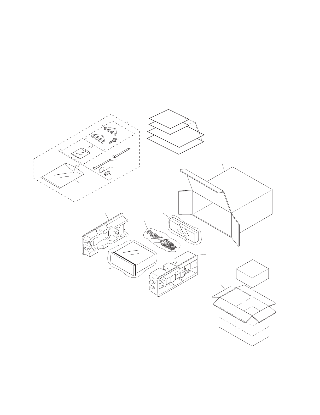
2.1 PACKING
4
7
11
3
10
9
8
6
5
16
2
17
12
15
14
13
1
18
1. SAFETY INFORMATION
This service manual is intended for qualified service technicians; it is not meant for the casual do-it-yourselfer.
Qualified technicians have the necessary test equipment and tools, and have been trained to properly and safely repair
complex products such as those covered by this manual.
Improperly performed repairs can adversely affect the safety and reliability of the product and may void the warranty.
If you are not qualified to perform the repair of this product properly and safely, you should mot risk trying to do so
and refer the repair to a qualified service technician.

3
KEH-P4850J
NOTE:
- Parts marked by “*”are generally unavailable because they are not in our Master Spare Parts List.
- Screws adjacent to
∇ mark on the product are used for disassembly.
- PACKING SECTION PARTS LIST
Mark No. Description Part No.
1-1 Owner’s Manual CRD2788
(English, Spanish, Portuguese(B), Arabic)
1-2 Installation Manual CRD2790
(English, Spanish, Portuguese(B), Arabic)
2 Cord Assy CDE5798
3 Spring CBH-865
4 Screw Assy CEA2003
5 Screw CBA1284
* 6 Polyethylene Bag CEG-127
7 Screw CRZ50P090FMC
8 Screw TRZ50P080FMC
* 9 Polyethylene Bag CEG-158
10 Handle CNC5395
11 Bush CNV1009
12 Polyethylene Bag CEG-162
13 Carton CHG3801
14 Contain Box CHL3801
15 Protector CHP2101
16 Protector CHP2102
17 Case Assy CXB3520
18 Accessory Assy CEA2002
4
KEH-P4850J
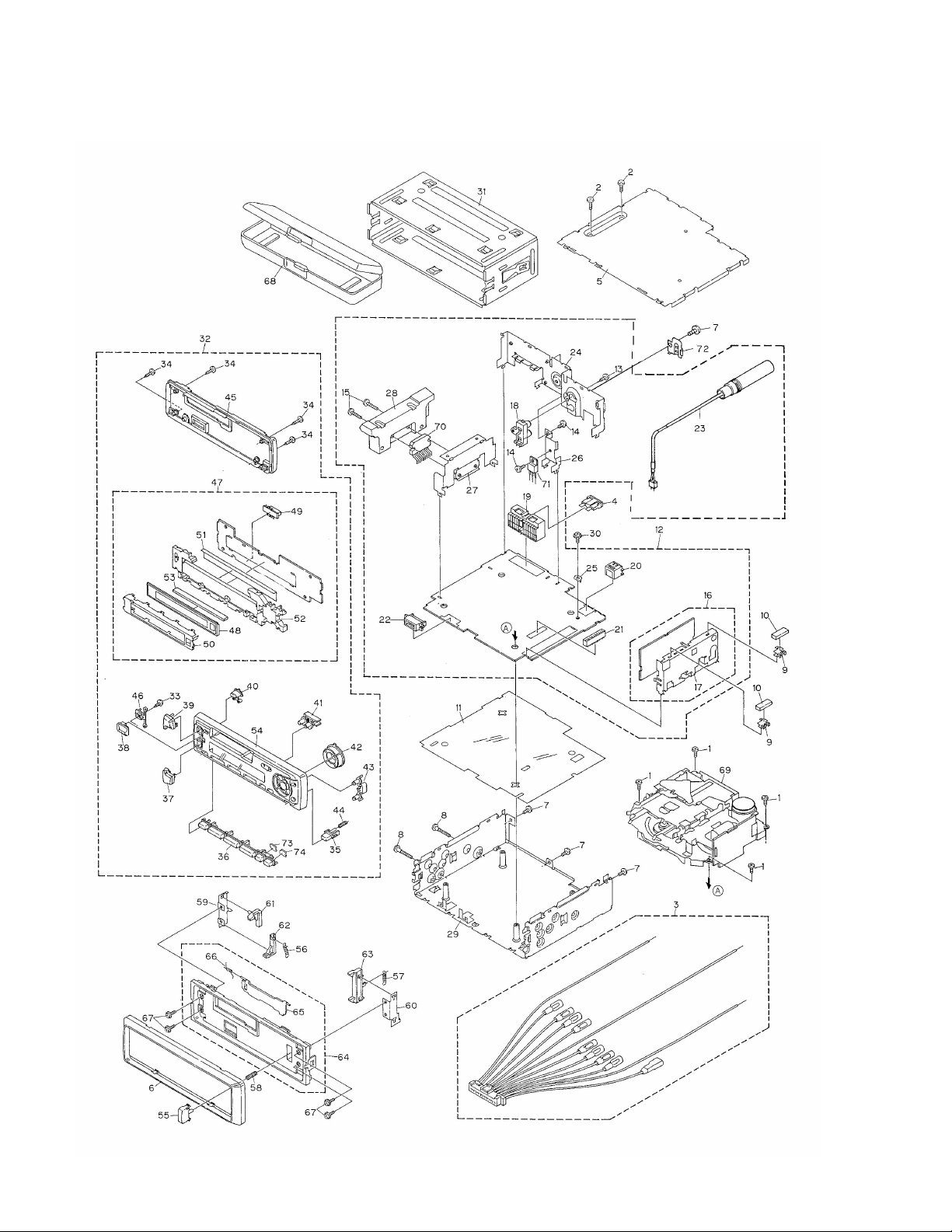
2.2 EXTERIOR

5
KEH-P4850J
1 Screw BSZ26P050FMC
2 Screw BSZ30P050FMC
3 Cord Assy CDE5798
4 Fuse(10A) CEK1136
5 Case CNB2350
6 Panel CNS5132
7 Screw BSZ30P050FMC
8 Screw BSZ30P200FMC
9 Holder CNC5704
10 Cushion CNM5210
11 Insulator CNM5963
12 Tuner Amp Unit CWM6253
13 Screw BPZ26P080FMC
14 Screw BSZ26P080FMC
15 Screw BSZ26P160FMC
16 Tuner Unit CWE1430
17 Holder CNC6122
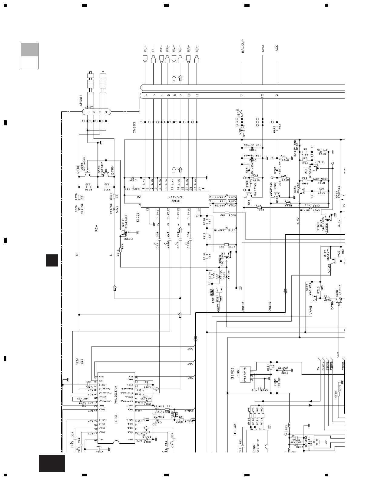
18 Pin Jack(CN301) CKB1028
19 Plug(CN603) CKM1270
20 Connector(CN701) CKS3408
21 Connector(CN602) CKS3568
22 Connector(CN601) CKS3581
23 Antenna Cable(CN403) CDH1274
24 Panel CNB2491
25 Holder CNC2218
26 Holder CNC6845
27 Holder CNC7996
28 Heat Sink CNR1505
29 Chassis Unit CXB3012
30 Screw ISS26P055FUC
31 Holder CNC6798
32 Detach Grille Assy CXB4247
33 Screw BPZ20P060FMC
34 Screw BPZ20P100FZK
35 Button(Detach) CAC5789
36 Button(1-6) CAC5794
37 Button(-) CAC5930
38 Button(EQ) CAC6135
39 Button(+) CAC5783
40 Button(Eject) CAC5793
41 Button(Display) CAC5788
42 Button(Cross) CAC5786
43 Button(A,B) CAC5787
44 Spring CBH2103
45 Cover CNS5130
46 Housing CNV5528
47 Keyboard Unit CWM6264
48 LCD(LCD1901) CAW1543
49 Connector(CN1901) CKS3580
50 Holder CNC7981
51 Sheet CNM5941
52 Lighting Conductor CNV5527
53 Connector CNV5531
54 Grille Unit CXB4147
55 Button CAC5180
56 Spring CBH1834
57 Spring CBH1835
58 Spring CBH2182
59 Bracket CNC6135
60 Bracket CNC6791
61 Arm CNV4692
62 Arm CNV4693
63 Arm CNV4951
64 Panel Unit CXB3019
65 Door CAT2028
66 Spring CBH1838
67 Screw IMS20P030FZK
68 Case Assy CXB3520
69
Cassette Mechanism ModuleEXK3695
70 IC(IC302) TDA7384
71 Transistor(Q904) 2SD2396
72 Holder CNC4963
73 Sheet CNM6292
74 Sheet CNM6293
- EXTERIOR SECTION PARTS LIST
Mark No. Description Part No. Mark No. Description Part No.
6
KEH-P4850J
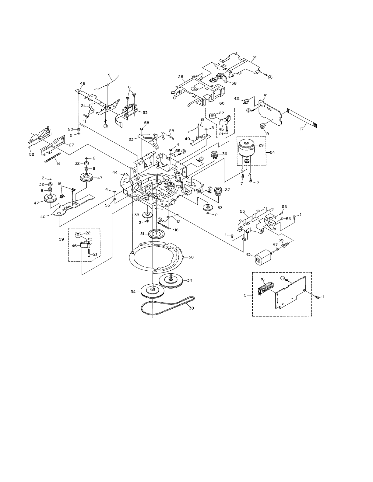
2.3 CASSETTE MECHANISM MODULE

7
KEH-P4850J
Mark No. Description Part No. Mark No. Description Part No.
1 Screw BSZ20P040FMC
2 Washer CBF1037
3 Washer CBF1038
4 Washer CBG1003
5 Deck Unit EWM1021
6 Screw EBA1028
7 Screw EBA1037
8 Spring EBH1531
9 Spring EBH1575
10 Plug(CN251) CKS3540
11 Spring EBH1515
12 Spring EBH1587
13 Spring EBH1517
14 Spring EBH1518
15 •••••
16 Spring EBH1537
17 Cord EDD1020
18 Photo-interrupter
(EGN2,3) EGN1006
19 Photo-interrupter(EGN1) EGN1005
20 Roller ENR1031
21 Shaft ELA1373
22 Pinch Roller ENV1518
23 Arm ENC1489
24 Arm ENC1397
25 Guide ENC1481
26 Holder ENC1417
27 Lever ENC1448
28 Arm ENC1488
* 29 Motor EXM1031
30 Belt ENT1027
31 Gear ENV1347
32 Collar ENV1508
33 Gear ENV1350
34 Flywheel ENV1500
35 Worm Gear ENV1439
36 Worm Wheel ENV1440
37 Gear ENR1028
38 Lever ENV1442
39 •••••
40 Gathering PCB ENX1037
41 Gathering PCB ENX1042
42 Switch(S1) ESG1004
43 Motor Unit(M2) EXA1485
44 Chassis Unit EXA1511
45 Pinch Holder ENV1485
46 Pinch Holder ENV1486
47 Reel Unit EXA1543
48 Head Base Unit EXA1457
49 Lever Unit EXA1438
50 Gear Unit EXA1574
51 Frame Unit EXA1458
52 Lever Unit EXA1439
53 Head Assy(HD1) EXA1506
54 Motor Unit(M1) EXA1490
55 Washer HBF-179
56 Screw BMZ20P022FMC
57 Spring EBH1545
58 Washer YE20FUC
59 Pinch Holder Unit EXA1529
60 Pinch Holder Unit EXA1528
- CASSETTE MECHANISM MODULE SECTION PARTS LIST
8
KEH-P4850J
A
1
234
B
C
D
12
34
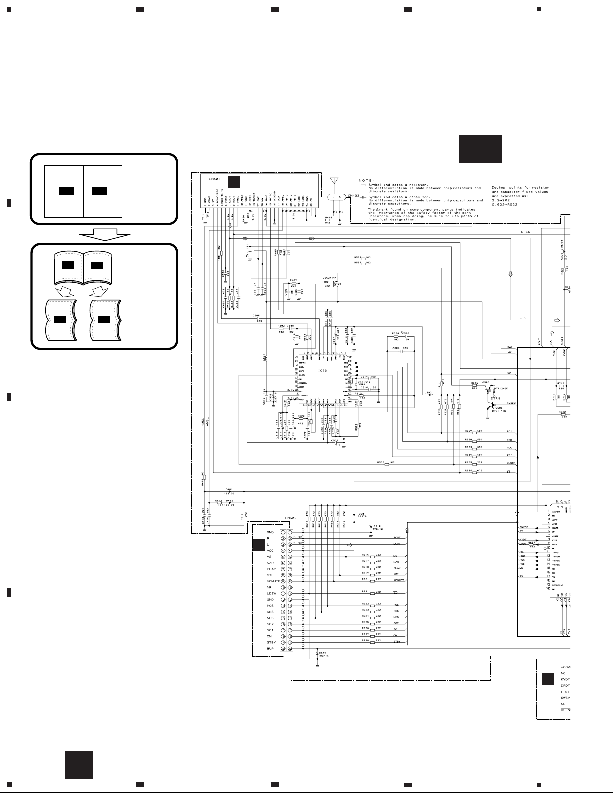
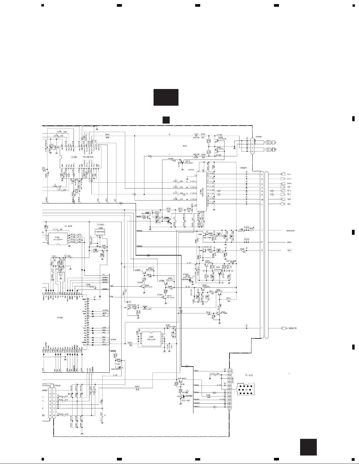
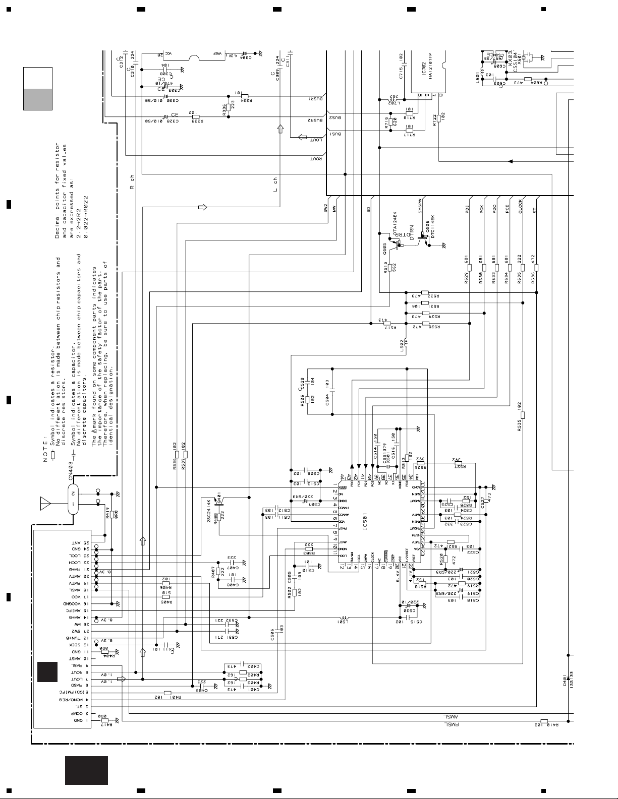
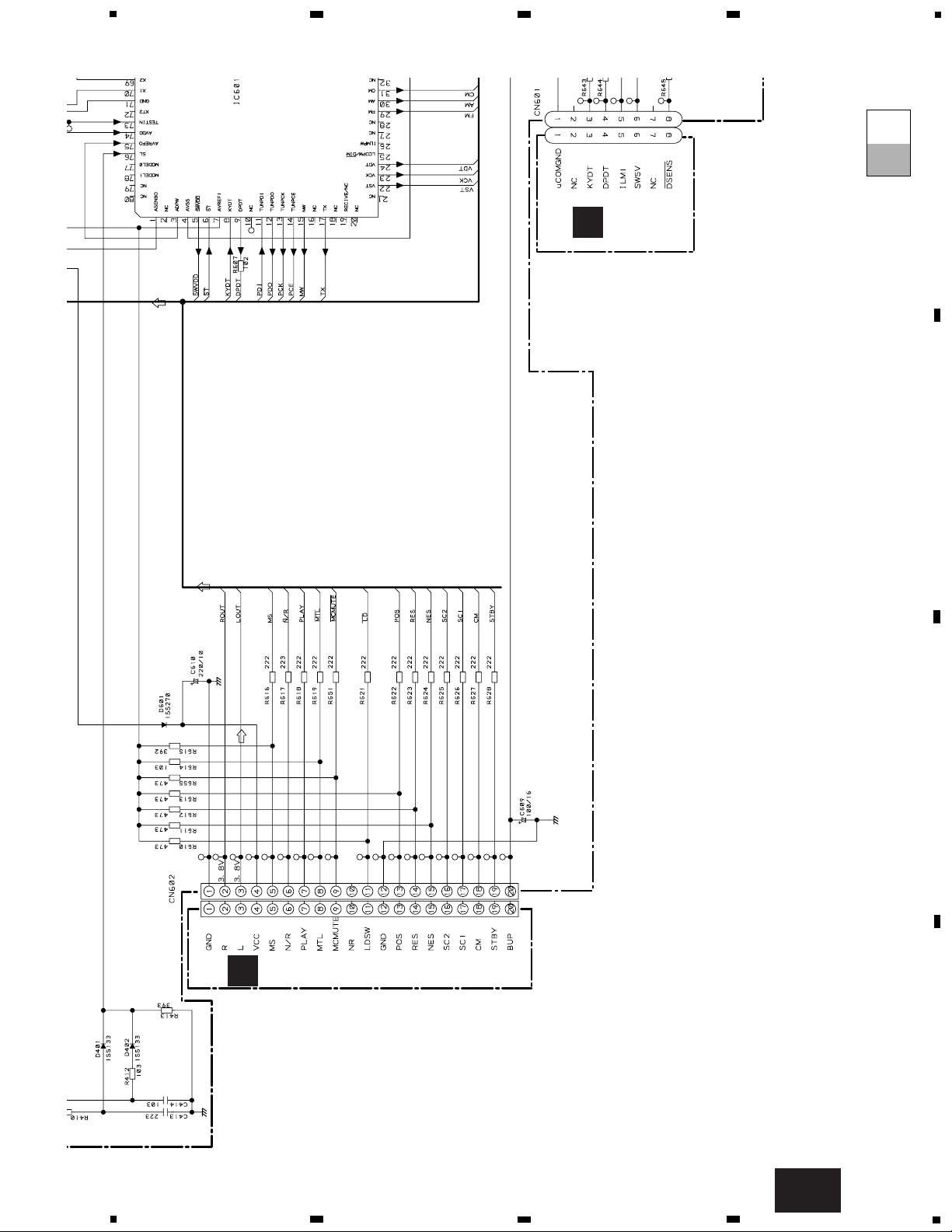
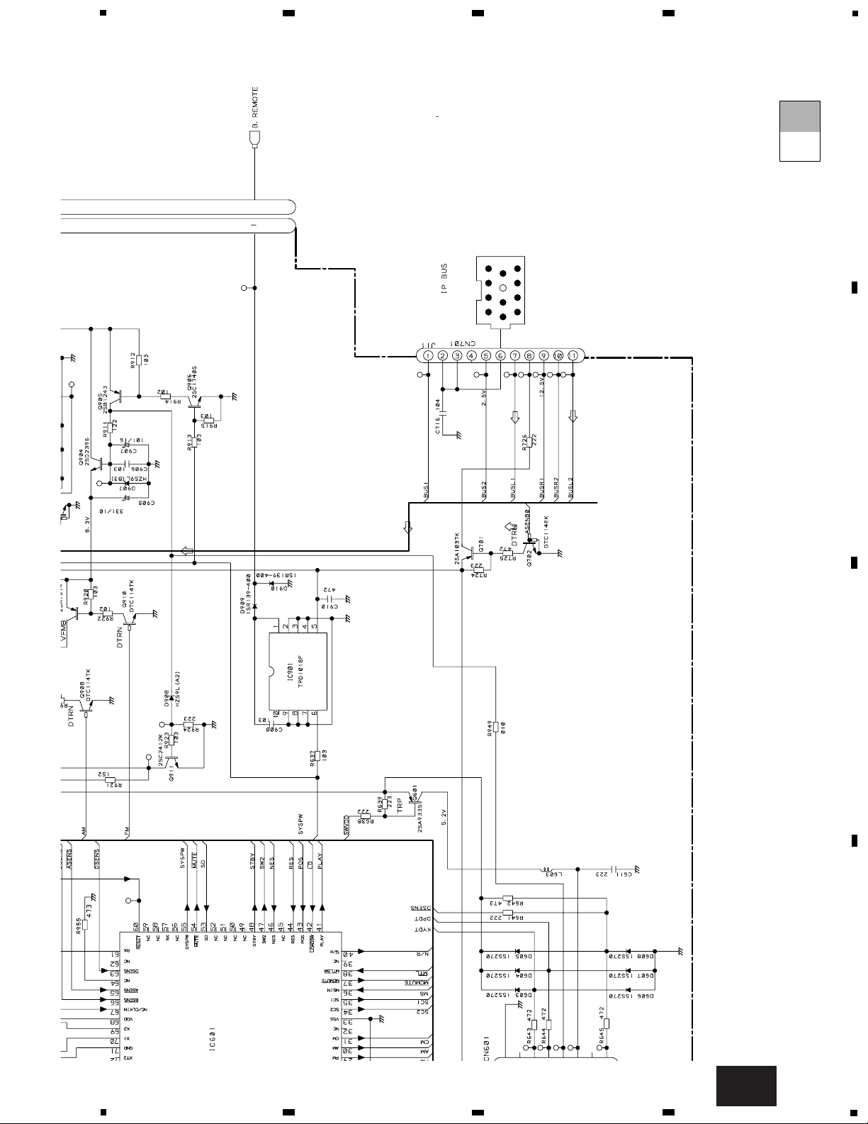
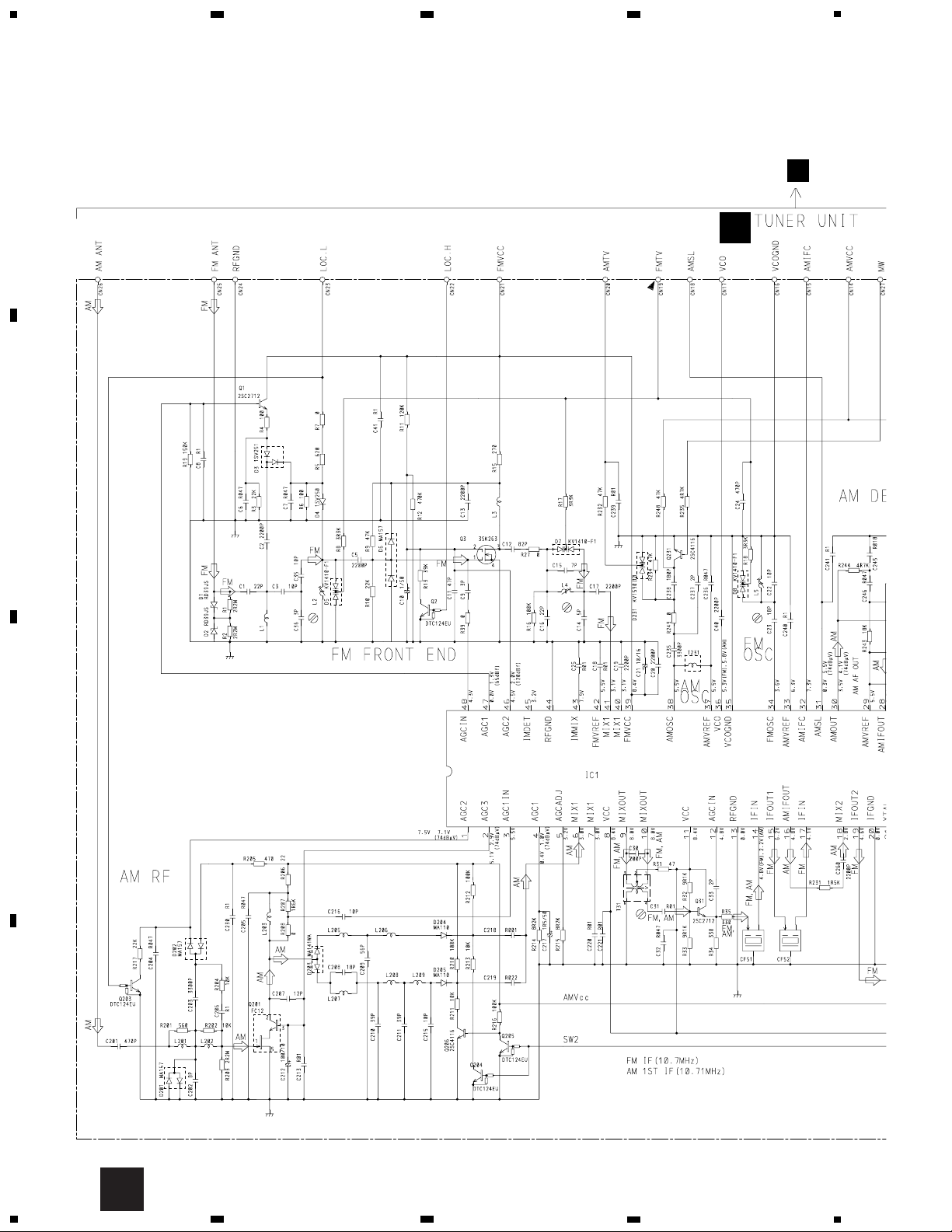
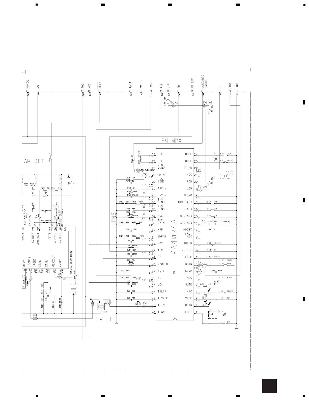
3. SCHEMATIC DIAGRAM
3.1 OVERALL CONNECTION DIAGRAM(GUIDE PAGE)
Note: When ordering service parts, be sure to refer to “EXPLODED VIEWS AND PARTS LIST” or “ELECTRICAL PARTS
LIST”.
A-a A-b
A-a
A-b
A-b
A-a
Large size
SCH diagram
Guide page
Detailed page
4R7/16
7.2MHz
B
D
C
TUNER UNIT
DECK UNIT
KEYBOARD UNI
TAPE: -9dBs
FM: -15.5dBs
AM: -22dBs
For resistors and capacitors in the circuit diagrams, their resistance values or
capacitance values are expressed in codes:
Ex. *Resistors
Code Practical value
123 12k ohms
103 10k ohms
*Capacitors
Code Practical value
103 10kpF(0.01uF)
101/10 100uF/10V
CN19
PM2006A
A-a
A
9
KEH-P4850J
5
6
7
8
A
B
C
D
5
6
7
8
3300/16
600µH
4.194MHz
PE5053A
A
TUNER AMP UNIT
CD: +2.2dBs
FM: +9.6dBs
AM: -3.1dBs
TAPE: -4dBs
CD: +10.3dBs
FM: +35.6dBs
AM: +29.1dBs
TAPE: +22.0dBs
CD: +36.3dBs
SYSTEM CONTROLLER
IP-BUS DRIVER
ELECTRONIC VOLUME
POWER AMP
RESET
8V REGULATER
IP-BUS
CEK1136
TAPE: -4.2dBs
332/16
A
A-b
10
KEH-P4850J
A
1
234
B
C
D
12
34
4R7/16
7.2MHz
B
TUNER UNIT
FM: -15.5dBs
AM: -22dBs
IP-BUS DR
ELE
PM2006A
A-a
A-a
A-b
11
KEH-P4850J
5
6
7
8
A
B
C
D
5
6
7
8
PE5053A
D
C
DECK UNIT
KEYBOARD UNIT
TAPE: -9dBs
SYSTEM CON
For resistors and capacitors in the circuit diagrams, their resistance values or
capacitance values are expressed in codes:
Ex. *Resistors
Code Practical value
123 12k ohms
103 10k ohms
*Capacitors
Code Practical value
103 10kpF(0.01uF)
101/10 100uF/10V
CN1901
A-a
A-a
A-b
12
KEH-P4850J
A
1
234
B
C
D
12
34
3300/16
600µH
4.194MHz
A
TUNER AMP UNIT
FM: +9.6dBs
AM: -3.1dBs
TAPE: -4dBs
CD: +10.3dBs
FM: +35.6dBs
AM: +29.1dBs
TAPE: +22.0dBs
CD: +36.3dBs
ELECTRONIC VOLUME
POWER AMP
RESET
8V REGULATER
CEK1136
TAPE: -4.2dBs
332/16
A-a
A-b
A-b
13
KEH-P4850J
5
6
7
8
A
B
C
D
5
6
7
8
PE5053A
CD: +2.2dBs
8V REGULATER
IP-BUS
A-b
A-a
A-b
14
KEH-P4850J
A
1
234
B
C
D
12
34
3.2 TUNER UNIT
B
PA4023B
B
A
15
KEH-P4850J
5
6
7
8
A
B
C
D
5
6
7
8
B
 Loading...