


Service KEH-P4850/X1M/ES |
|
Manual |
ORDER NO. |
|
|
|
CRT2261 |
MULTI-CD CONTROL HIGH POWER CASSETTE PLAYER WITH FM/AM TUNER
KEH-P4800 X1M/UC
KEH-P4850 X1M/ES
NOTE:
-See the separate manual CX-631(CRT1640) for the cassette mechanism description.
-The cassette mechanism assy employed in this model is one of 2L series.
-This service manual does not describe the CD test mode.
For the operations in the CD test mode, refer to the CD player's Service Manual.
CONTENTS
1. |
SAFETY INFORMATION............................................ |
2 |
7. |
GENERAL INFORMATION....................................... |
41 |
2. |
EXPLODED VIEWS AND PARTS LIST ...................... |
2 |
|
7.1 PARTS ................................................................ |
41 |
3. |
SCHEMATIC DIAGRAM............................................. |
8 |
|
7.1.1 IC ............................................................... |
41 |
4. |
PCB CONNECTION DIAGRAM................................ |
22 |
|
7.1.2 DISPLAY ................................................... |
45 |
5. |
ELECTRICAL PARTS LIST........................................ |
32 |
|
7.2DISASSEMBLY ................................................... |
46 |
6. |
ADJUSTMENT ......................................................... |
39 |
|
7.3BLOCK DIAGRAM .............................................. |
47 |
|
|
|
8. |
OPERATIONS AND SPECIFICATIONS.................... |
48 |
|
|
|
|||
PIONEER ELECTRONIC CORPORATION |
4-1, Meguro 1-Chome, Meguro-ku, Tokyo 153-8654, Japan |
|
|||
PIONEER ELECTRONICS SERVICE INC. P.O.Box 1760, Long Beach, CA 90801-1760 U.S.A. |
|
||||
PIONEER ELECTRONIC [EUROPE] N.V. Haven 1087 Keetberglaan 1, 9120 Melsele, Belgium
PIONEER ELECTRONICS ASIACENTRE PTE.LTD. 501 Orchard Road, #10-00, Wheelock Place, Singapore 238880
C PIONEER ELECTRONIC CORPORATION 1998
K-ZZU. OCT. 1998 Printed in Japan
KEH-P4800,P4850
1. SAFETY INFORMATION
UC model
CAUTION
This service manual is intended for qualified service technicians; it is not meant for the casual do-it-yourselfer. Qualified technicians have the necessary test equipment and tools, and have been trained to properly and safely repair complex products such as those covered by this manual.
Improperly performed repairs can adversely affect the safety and reliability of the product and may void the warranty. If you are not qualified to perform the repair of this product properly and safely; you should not risk trying to do so and refer the repair to a qualified service technician.
WARNING
Lead in solder used in this product is listed by the California Health and Welfare agency as a known reproductive toxicant which may cause birth defects or other reproductive harm (California Health and Safety Code, Section 25249.5). When servicing or handling circuit boards and other components which contain lead in solder, avoid unprotected skin contact with the solder. Also, when soldering do not inhale any smoke or fumes produced.
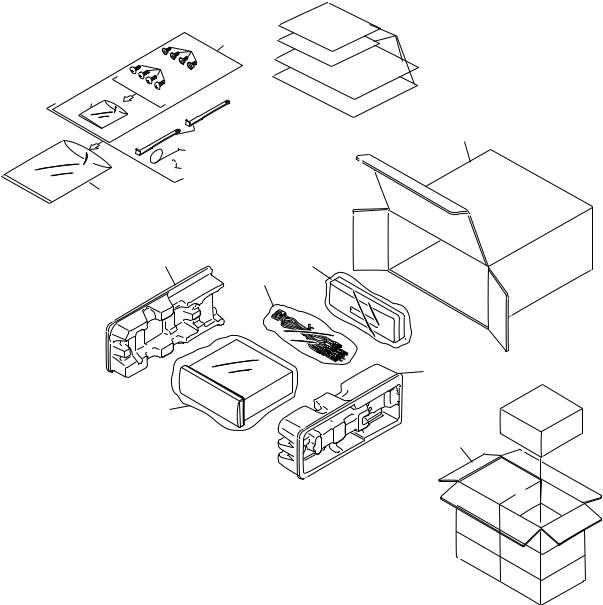
2. EXPLODED VIEWS AND PARTS LIST
2.1 PACKING
1
7 4
8
 5
5
6
10 |
13 |
3
 11
11
16 |
17 |
|
2 |
15
12
14
2
KEH-P4800,P4850
NOTE:
-Parts marked by “*”are generally unavailable because they are not in our Master Spare Parts List.
-Screws adjacent to mark on the product are used for disassembly.
-PACKING SECTION PARTS LIST
|
|
|
Part No. |
|
Mark No. Description |
KEH-P4800/X1M/UC |
KEH-P4850/X1M/ES |
||
* |
1-1 |
Card |
ARY1048 |
Not used |
|
1-2 |
Owner’s Manual |
CRD2783 |
CRD2785 |
|
1-3 |
Installation Manual |
CRD2784 |
CRD2787 |
|
1-4 |
Owner’s Manual |
Not used |
CRD2786 |
|
2 |
Cord Assy |
CDE5798 |
CDE5798 |
|
3 |
Spring |
CBH1650 |
CBH1650 |
|
4 |
Screw Assy |
CEA2351 |
CEA2351 |
|
5 |
Screw |
CBA1304 |
CBA1304 |
* |
6 |
Polyethylene Bag |
CEG-127 |
CEG-127 |
|
7 |
Screw |
CRZ50P090FMC |
CRZ50P090FMC |
|
8 |
Screw |
TRZ50P080FMC |
TRZ50P080FMC |
* |
9 |
Polyethylene Bag |
CEG-158 |
CEG-158 |
|
10 |
Handle |
CNC5395 |
CNC5395 |
|
11 |
Bush |
CNV3930 |
CNV3930 |
|
12 |
Polyethylene Bag |
CEG1173 |
CEG-162 |
|
13 |
Carton |
CHG3570 |
CHG3571 |
|
14 |
Contain Box |
CHL3570 |
CHL3571 |
|
15 |
Protector |
CHP2101 |
CHP2101 |
|
16 |
Protector |
CHP2102 |
CHP2102 |
|
17 |
Case Assy |
CXB3520 |
CXB3520 |
- Owner's Manual, Installation Manual
Model |
Part No. |
Language |
KEH-P4800/X1M/UC |
CRD2783 |
English, French, Spanish |
|
CRD2784 |
English, French, Spanish |
KEH-P4850/X1M/ES |
CRD2785 |
English, Spanish, Portuguese(B) |
|
CRD2786 |
Chinese, Arabic |
|
CRD2787 |
English, Spanish, |
|
|
Portuguese(B), Chinese, Arabic |
3
KEH-P4800,P4850
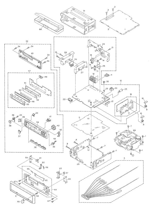
2.2 EXTERIOR
4
KEH-P4800,P4850
(1) EXTERIOR SECTION PARTS LIST
Mark No. Description |
Part No. |
|
Mark No. Description |
Part No. |
||
1 |
Screw |
BSZ26P050FMC |
36 |
Button(1-6) |
CAC5794 |
|
2 |
Screw |
BSZ30P050FMC |
37 |
Button(-) |
CAC5930 |
|
3 |
Cord Assy |
CDE5798 |
38 |
Button(EQ) |
CAC6135 |
|
4 |
Fuse(10A) |
CEK1136 |
39 |
Button(+) |
CAC5783 |
|
5 |
Case |
CNB2350 |
40 |
Button(Eject) |
CAC5793 |
|
6 |
Panel |
CNS5132 |
41 |
Button(Display) |
CAC5788 |
|
7 |
Screw |
BSZ30P050FMC |
42 |
Button(Cross) |
CAC5786 |
|
8 |
Screw |
BSZ30P200FMC |
43 |
Button(A,B) |
CAC5787 |
|
9 |
Holder |
CNC5704 |
44 |
Spring |
CBH2103 |
|
10 |
Cushion |
CNM5210 |
45 |
Cover |
CNS5130 |
|
11 |
Insulator |
CNM5963 |
46 |
Housing |
CNV5528 |
|
12 |
Tuner Amp Unit |
See Contrast table(2) |
47 |
Keyboard Unit |
See Contrast table(2) |
|
13 |
Screw |
BPZ26P080FMC |
48 |
LCD(LCD1901) |
CAW1543 |
|
14 |
Screw |
BSZ26P080FMC |
49 |
Connector(CN1901) |
CKS3580 |
|
15 |
Screw |
BSZ26P160FMC |
50 |
Holder |
CNC7981 |
|
16 |
FM/AM Tuner Unit |
See Contrast table(2) |
51 |
Sheet |
CNM5941 |
|
17 |
Holder |
CNC6554 |
52 |
Lighting Conductor |
CNV5527 |
|
18 |
Pin Jack(CN301) |
CKB1035 |
53 |
Connector |
CNV5531 |
|
19 |
Plug(CN603) |
CKM1270 |
54 |
Grille Unit |
See Contrast table(2) |
|
20 |
Connector(CN701) |
CKS3408 |
55 |
Button |
CAC4836 |
|
21 |
Connector(CN602) |
CKS3568 |
56 |
Spring |
CBH1834 |
|
22 |
Connector(CN601) |
CKS3581 |
57 |
Spring |
CBH1835 |
|
23 |
Antenna Jack(CN402) |
CKX1056 |
58 |
Spring |
CBH2182 |
|
24 |
Panel |
CNB2343 |
59 |
Bracket |
CNC6135 |
|
25 |
Holder |
CNC5399 |
60 |
Bracket |
CNC6791 |
|
26 |
Holder |
CNC6845 |
61 |
Arm |
CNV4692 |
|
27 |
Holder |
CNC7996 |
62 |
Arm |
CNV4693 |
|
28 |
Heat Sink |
CNR1505 |
63 |
Arm |
CNV4728 |
|
29 |
Chassis Unit |
CXB3012 |
64 |
Panel Unit |
CXB3019 |
|
30 |
Screw |
ISS26P055FUC |
65 |
Door |
CAT2028 |
|
31 |
Holder Unit |
CXB2687 |
66 |
Spring |
CBH1838 |
|
32 |
Detach Grille Assy |
See Contrast table(2) |
67 |
Screw |
IMS20P030FZK |
|
33 |
Screw |
BPZ20P060FMC |
68 |
Case Assy |
CXB3520 |
|
34 |
Screw |
BPZ20P100FZK |
69 |
Cassette Mechanism ModuleEXK3695 |
||
35 |
Button(Detach) |
CAC5789 |
|
|
|
|
|
|
|
70 |
IC(IC302) |
TDA7384 |
|
|
|
|
71 |
Transistor(Q904) |
2SD2396 |
|
5
KEH-P4800,P4850
(2)CONTRAST TABLE
KEH-P4800/X1M/UC and KEH-P4850/X1M/ES have
the same construction except for the following:
|
|
Part No. |
|
Mark No. Description |
KEH-P4800/X1M/UC |
KEH-P4850/X1M/ES |
|
12 |
Tuner Amp Unit |
CWM6248 |
CWM6249 |
16 |
FM/AM Tuner Unit |
CWE1467 |
CWE1486 |
32 |
Detach Grille Assy |
CXB3322 |
CXB3323 |
47 |
Keyboard Unit |
CWM6259 |
CWM6260 |
54 |
Grille Unit |
CXB4065 |
CXB4066 |
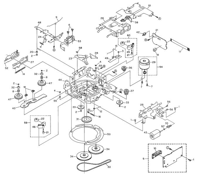
2.3 CASSETTE MECHANISM MODULE
6
KEH-P4800,P4850
- CASSETTE MECHANISM MODULE SECTION PARTS LIST
Mark No. Description |
Part No. |
Mark No. Description |
Part No. |
|||
|
|
|
|
|
|
|
1 |
Screw |
BSZ20P040FMC |
46 |
Pinch Holder |
ENV1486 |
|
2 |
Washer |
CBF1037 |
47 |
Reel Unit |
EXA1543 |
|
3 |
Washer |
CBF1038 |
48 |
Head Base Unit |
EXA1457 |
|
4 |
Washer |
CBG1003 |
49 |
Lever Unit |
EXA1438 |
|
5 |
Deck Unit |
EWM1021 |
50 |
Gear Unit |
EXA1574 |
|
6 |
Screw |
EBA1028 |
51 |
Frame Unit |
EXA1458 |
|
7 |
Screw |
EBA1037 |
52 |
Lever Unit |
EXA1439 |
|
8 |
Spring |
EBH1531 |
53 |
Head Assy(HD1) |
EXA1506 |
|
9 |
Spring |
EBH1575 |
54 |
Motor Unit(M1) |
EXA1490 |
|
10 |
Plug(CN251) |
CKS3540 |
55 |
Washer |
HBF-179 |
|
11 |
Spring |
EBH1515 |
56 |
Screw |
BMZ20P022FMC |
|
12 |
Spring |
EBH1587 |
57 |
Spring |
EBH1545 |
|
13 |
Spring |
EBH1517 |
58 |
Washer |
YE20FUC |
|
14 |
Spring |
EBH1518 |
59 |
Pinch Holder Unit |
EXA1529 |
|
15 |
••••• |
|
60 |
Pinch Holder Unit |
EXA1528 |
|
16 |
Spring |
EBH1537 |
|
|
|
|
17 |
Cord |
EDD1020 |
|
|
|
|
18Photo-interrupter(EGN2,3) EGN1006
19Photo-interrupter(EGN1) EGN1005
20 |
Roller |
ENR1031 |
21 |
Shaft |
ELA1373 |
22 |
Pinch Roller |
ENV1518 |
23 |
Arm |
ENC1489 |
24 |
Arm |
ENC1397 |
25 |
Guide |
ENC1481 |
26 |
Holder |
ENC1417 |
27 |
Lever |
ENC1448 |
28 |
Arm |
ENC1488 |
* 29 Motor |
EXM1031 |
|
30 |
Belt |
ENT1027 |
31 |
Gear |
ENV1347 |
32 |
Collar |
ENV1508 |
33 |
Gear |
ENV1350 |
34 |
Flywheel |
ENV1500 |
35 |
Worm Gear |
ENV1439 |
36 |
Worm Wheel |
ENV1440 |
37 |
Gear |
ENR1028 |
38 |
Lever |
ENV1442 |
39 |
••••• |
|
40 |
Gathering PCB |
ENX1037 |
41 |
Gathering PCB |
ENX1042 |
42 |
Switch(S1) |
ESG1004 |
43 |
Motor Unit(M2) |
EXA1485 |
44 |
Chassis Unit |
EXA1511 |
45 |
Pinch Holder |
ENV1485 |
7
1 |
|
2 |
|
3 |
|
4 |
|
|
|
KEH-P4800,P4850
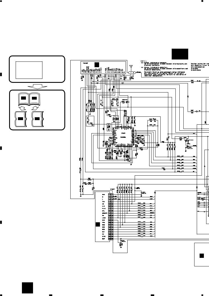
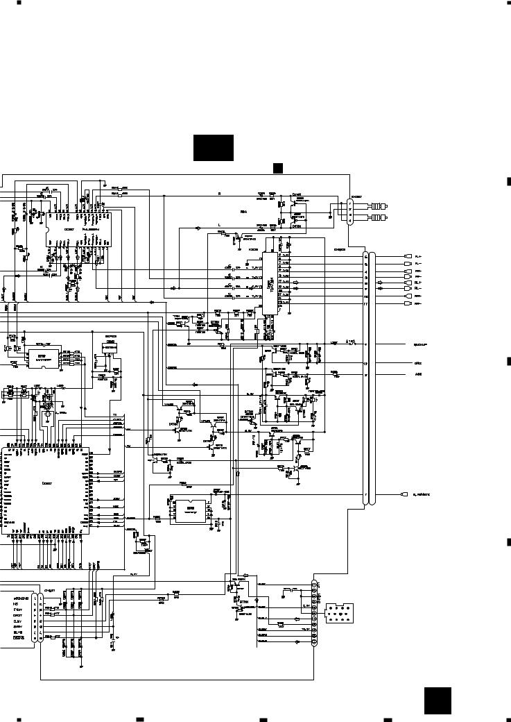
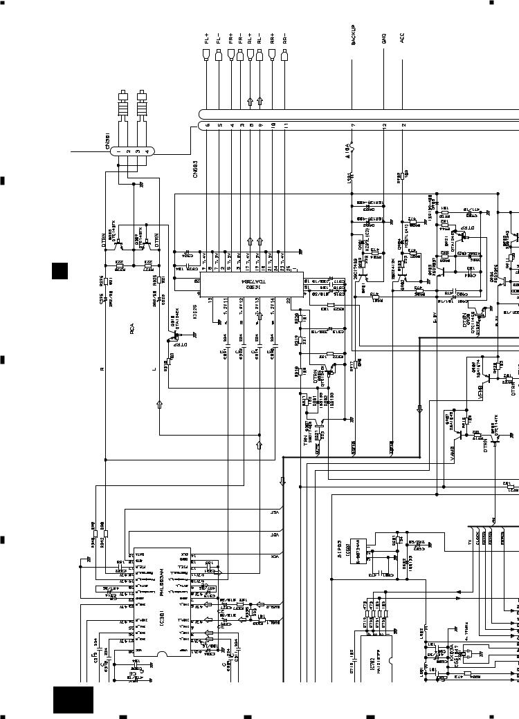
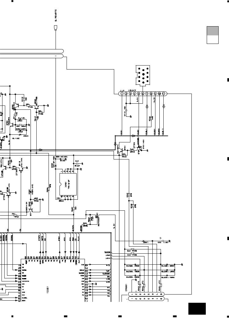
3. SCHEMATIC DIAGRAM
3.1 OVERALL CONNECTION DIAGRAM(GUIDE PAGE)
A
Note: When ordering service parts, be sure to refer to “EXPLODED VIEWS AND PARTS LIST” or “ELECTRICAL PARTS
LIST”.
|
|
|
|
|
|
Large size |
|
|
|
|
|
|
SCH diagram |
|
A-a |
|
|
A-b |
|
|
|
|
|
|
|
||
|
|
|
|
|
|
|
A-a |
A-b |
Guide page |
|
B
Detailed page
A-a A-b
C
D
A-a
B FM/AM TUNER UNIT
331:UC model |
510:ES model |
|
|
FM: -15.5dBs |
|
|
AM: -22dBs |
UC model |
|
|
ES model |
|
|
4R7/16 |
|
|
|
TAPE: -9dBs |
|
DECK UNIT |
|
|
D |
|
|
For resistors and capacitors in the circuit diagrams, their resistance values or |
|
|
capacitance values are expressed in codes: |
|
|
Ex. *Resistors |
|
|
Code |
Practical value |
|
123 |
12k ohms |
|
103 |
10k ohms |
C |
*Capacitors |
||
Code |
Practical value |
|
103 |
10kpF(0.01uF) |
KEYBOARD UNIT |
101/10 |
100uF/10V |
|
8 A
1 |
2 |
3 |
4 |
5 |
|
6 |
|
7 |
|
8 |
|
|
|
KEH-P4800,P4850
A
A-b
A TUNER AMP UNIT
ELECTRONIC VOLUME
332/16
TAPE: -4.2dBs
FM: +35.6dBs
AM: +29.1dBs
TAPE: +22.0dBs
CD: +36.3dBs
|
FM: +9.6dBs |
POWER AMP |
|
|
|
AM: -3.1dBs |
|
|
|
|
TAPE: -4dBs |
|
|
|
|
CD: +10.3dBs |
|
|
B |
|
|
|
|
|
IP-BUS DRIVER |
|
|
|
|
|
RESET |
|
CEK1136 |
|
102:UC |
|
|
|
|
103:ES |
|
|
|
|
|
|
8V REGULATER |
|
|
|
|
|
|
C |
SYSTEM CONTROLLER |
|
|
|
|
PD4973A |
|
|
|
|
|
|
CD: +2.2dBs |
|
|
|
|
IP-BUS |
|
|
|
|
|
|
D |
CN1901 |
|
|
|
|
|
|
|
A |
9 |
5 |
6 |
7 |
8 |
|

A
B
1 |
2 |
KEH-P4800,P4850
A-a A-b
-15.5dBs |
-22dBs |
FM: |
AM: |
3 |
4 |
102: |
103:E |
C
D
B FM/AM TUNER UNIT
510:ESmodel 331:UCmodel
4R7/16
UC model
ES model
10 A-a
1 |
2 |
3 |
4 |
5 |
6 |
|
|
|
|
|
|
7 |
|
|
8 |
|
|
|
|
|
|
|
|
|
|
|
KEH-P4800,P4850 |
SYSTE |
|
|
|
|
|
|
|
|
|
CN1901 |
A-b |
|
|
|
|
|
|
|
|
|
|
UNIT |
A-a |
|
|
|
|
|
|
|
C KEYBOARD |
|
|||
|
circuit diagrams, their resistance values or |
in codes: |
|
|
|
|
|
|
|
|
|
TAPE: -9dBs |
For resistors and capacitors in the |
capacitance values are expressed |
Ex. *Resistors |
Code Practical value |
123 12k ohms |
103 10k ohms |
*Capacitors |
Code Practical value |
103 10kpF(0.01uF) |
101/10 100uF/10V |
|
A
B
C
DECKUNIT |
D |
|
D
A-a 11
5 |
|
6 |
|
7 |
|
|
|
|
|
|
|||
|
|
8 |
||||
|
|
|
|
|
||
1 |
|
2 |
|
3 |
|
4 |
|
|
|
KEH-P4800,P4850
A
B
A-b |
|
FM: +35.6dBs AM: +29.1dBs TAPE: +22.0dBs CD: +36.3dBs |
A-a |
TAPE: -4.2dBs |
|
|
AMP UNIT |
|
TUNER |
332/16 |
|
|
A |
|
POWER AMP
CEK1136 8V REGULATER
C |
FM: +9.6dBs |
AM: -3.1dBs TAPE: -4dBs CD: +10.3dBs |
|
|
RESET
|
VOLUME |
DRIVERBUS |
D |
ELECTRONIC |
|
|
|
|
|
|
IP- |
12 A-b
1 |
2 |
3 |
4 |
5 |
|
6 |
|
7 |
|
8 |
|
|
|
KEH-P4800,P4850
A-a A-b
REGULATER |
IP-BUS |
8V |
|
|
CD: +2.2dBs |
A
B
C
CONTROLLER |
PD4973A |
|
|
D |
|
A-b |
|
||
5 |
6 |
7 |
13 |
|
8 |
|
1 |
|
2 |
|
3 |
|
4 |
|
|
|
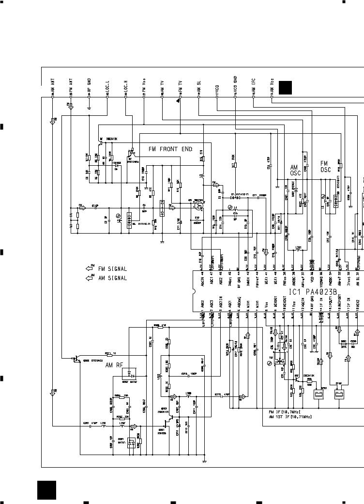
KEH-P4800,P4850
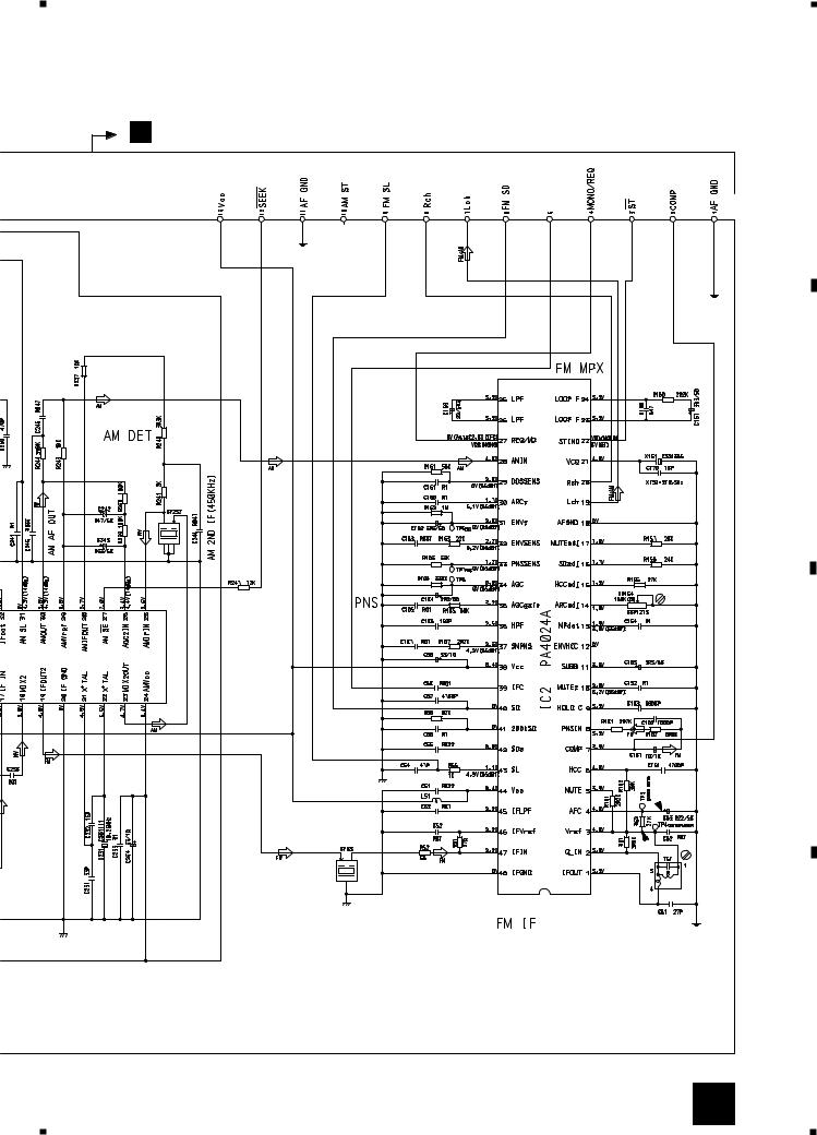
3.2 FM/AM TUNER UNIT
- KEH-P48000/X1M/UC
A
B FM/AM TUNER U
B
|
|
|
MA157 |
D1 RD39JS |
R1 |
2R2M |
D6 |
D2 RD39JS |
R2 |
2R2M |
|
C
1
2
3
D
14 B
1 |
2 |
3 |
4 |
R UNIT
5 |
|
6 |
|
7 |
|
8 |
|
|
|
KEH-P4800,P4850
A
A
IFC
B
C
D
B 15
5 |
|
6 |
|
7 |
|
8 |
|
|
|
||||
|
|
|

1 |
|
2 |
|
3 |
|
4 |
|
|
|
KEH-P4800,P4850
- KEH-P4850/X1M/ES
A
B FM/AM TUNER U
B
|
|
|
MA157 |
D1 RD39JS |
R1 |
2R2M |
D6 |
D2 RD39JS |
R2 |
2R2M |
|
C
1
2
3
D
16 B
1 |
2 |
3 |
4 |
 Loading...