

Pioneer DV-K102, DVD-V550 User Manual

DVD PLAYER
DV-K102
DVD-V550
Operating Instructions
Please read through these operating instructions so you will know how to operate your model properly. After you
have finished reading the instructions, put them away in a safe place for future reference.
• This player is not suitable for commercial use.
IMPORTANT
CAUTION
RISK OF ELECTRIC SHOCK
DO NOT OPEN
The lightning flash with arrowhead symbol, within
an equilateral triangle, is intended to alert the user
to the presence of uninsulated "dangerous voltage"
within the product's enclosure that may be of
sufficient magnitude to constitute a risk of electric
shock to persons.
CAUTION:
TO PREVENT THE RISK OF ELECTRIC SHOCK,
DO NOT REMOVE COVER (OR BACK). NO
USER-SERVICEABLE PARTS INSIDE. REFER
SERVICING TO QUALIFIED SERVICE
PERSONNEL.
The exclamation point within an equilateral triangle
is intended to alert the user to the presence of
important operating and maintenance (servicing)
instructions in the literature accompanying the
appliance.
IMPORTANT SAFETY INSTRUCTIONS
READ INSTRUCTIONS — All the safety and
operating instructions should be read before
the product is operated.
RETAIN INSTRUCTIONS — The safety and
operating instructions should be retained for
future reference.
HEED WARNINGS — All warnings on the product
and in the operating instructions should be
adhered to.
FOLLOW INSTRUCTIONS — All operating and
use instructions should be followed.
CLEANING — Unplug this product from the wall
outlet before cleaning. The product should be
cleaned only with a polishing cloth or a soft dry
cloth. Never clean with furniture wax, benzine,
insecticides or other volatile liquids since they
may corrode the cabinet.
ATTACHMENTS — Do not use attachments not
recommended by the product manufacturer
as they may cause hazards.
WATER AND MOISTURE — Do not use this
product near water — for example, near a
bathtub, wash bowl, kitchen sink, or laundry
tub; in a wet basement; or near a swimming
pool; and the like.
ACCESSORIES — Do not place this product on
an unstable cart, stand, tripod, bracket, or
table. The product may fall, causing serious
injury to a child or adult, and serious damage
to the product. Use only with a cart, stand,
tripod, bracket, or table recommended by the
manufacturer, or sold with the product. Any
mounting of the product should follow the
manufacturer’s instructions, and should use a
mounting accessory recommended by the
manufacturer.
CART — A product and cart combination should
be moved with care. Quick stops, excessive
force, and uneven surfaces may cause the
product and cart combination to overturn.
VENTILATION — Slots and openings in the
cabinet are provided for ventilation and to
ensure reliable operation of the product and to
protect it from overheating, and these openings
must not be blocked or covered. The openings
should never be blocked by placing the product
on a bed, sofa, rug, or other similar surface.
This product should not be placed in a built-in
installation such as a bookcase or rack unless
proper ventilation is provided or the
manufacturer’s instructions have been
adhered to.
POWER SOURCES — This product should be
operated only from the type of power source
indicated on the marking label. If you are not
sure of the type of power supply to your
home, consult your product dealer or local
power company.
LOCATION – The appliance should be installed in
a stable location.
NONUSE PERIODS – The power cord of the
appliance should be unplugged from the outlet
when left unused for a long period of time.
2
GROUNDING OR POLARIZATION
• If this product is equipped with a polarized
alternating current line plug (a plug having one
blade wider than the other), it will fit into the
outlet only one way. This is a safety feature. If
you are unable to insert the plug fully into the
outlet, try reversing the plug. If the plug should
still fail to fit, contact your electrician to replace
your obsolete outlet. Do not defeat the safety
purpose of the polarized plug.
• If this product is equipped with a three-wire
grounding type plug, a plug having a third
(grounding) pin, it will only fit into a grounding
type power outlet. This is a safety feature. If
you are unable to insert the plug into the
outlet, contact your electrician to replace your
obsolete outlet. Do not defeat the safety
purpose of the grounding type plug.
POWER-CORD PROTECTION — Power-supply
cords should be routed so that they are not
likely to be walked on or pinched by items
placed upon or against them, paying particular
attention to cords at plugs, convenience
receptacles, and the point where they exit
from the product.
OUTDOOR ANTENNA GROUNDING — If an
outside antenna or cable system is connected
to the product, be sure the antenna or cable
system is grounded so as to provide some
protection against voltage surges and built-up
static charges. Article 810 of the National
Electrical Code, ANSI/NFPA 70, provides
information with regard to proper grounding of
the mast and supporting structure, grounding
of the lead-in wire to an antenna discharge
unit, size of grounding conductors, location of
antenna-discharge unit, connection to
grounding electrodes, and requirements for
the grounding electrode. See Figure A.
LIGHTNING — For added protection for this
product during a lightning storm, or when it is
left unattended and unused for long periods of
time, unplug it from the wall outlet and
disconnect the antenna or cable system. This
will prevent damage to the product due to
lightning and power-line surges.
POWER LINES — An outside antenna system
should not be located in the vicinity of overhead
power lines or other electric light or power
circuits, or where it can fall into such power
lines or circuits. When installing an outside
antenna system, extreme care should be taken
to keep from touching such power lines or
circuits as contact with them might be fatal.
OVERLOADING — Do not overload wall outlets,
extension cords, or integral convenience
receptacles as this can result in a risk of fire or
electric shock.
ELECTRIC
SERVICE
EQUIPMENT
OBJECT AND LIQUID ENTRY — Never push
objects of any kind into this product through
openings as they may touch dangerous voltage
points or short-out parts that could result in a
fire or electric shock. Never spill liquid of any
kind on the product.
SERVICING — Do not attempt to service this
product yourself as opening or removing
covers may expose you to dangerous voltage
or other hazards. Refer all servicing to qualified
service personnel.
DAMAGE REQUIRING SERVICE — Unplug this
product from the wall outlet and refer servicing
to qualified service personnel under the
following conditions:
• When the power-supply cord or plug is
damaged.
• If liquid has been spilled, or objects have fallen
into the product.
• If the product has been exposed to rain or
water.
• If the product does not operate normally by
following the operating instructions. Adjust
only those controls that are covered by the
operating instructions as an improper
adjustment of other controls may result in
damage and will often require extensive work
by a qualified technician to restore the product
to its normal operation.
• If the product has been dropped or damaged
in any way.
• When the product exhibits a distinct change in
performance — this indicates a need for
service.
REPLACEMENT PARTS — When replacement
parts are required, be sure the service
technician has used replacement parts
specified by the manufacturer or have the
same characteristics as the original part.
Unauthorized substitutions may result in fire,
electric shock, or other hazards.
SAFETY CHECK — Upon completion of any
service or repairs to this product, ask the
service technician to perform safety checks to
determine that the product is in proper
operating condition.
WALL OR CEILING MOUNTING — The product
should not be mounted to a wall or ceiling.
HEAT — The product should be situated away
from heat sources such as radiators, heat
registers, stoves, or other products (including
amplifiers) that produce heat.
ANTENNA
LEAD IN WIRE
GROUND
CLAMP
Fig. A
ANTENNA
DISCHARGE UNIT
(NEC SECTION 810-20)
GROUNDING CONDUCTORS
(NEC SECTION 810-21)
GROUND CLAMPS
POWER SERVICE GROUNDING
ELECTRODE SYSTEM
(NEC ART 250, PART H)
NEC — NATIONAL ELECTRICAL CODE

CONGRATULATIONS ON YOUR PURCHASE OF
THIS FINE PIONEER PRODUCT.
Pioneer is on the leading edge of DVD research for
consumer products and this unit incorporates the latest
technological developments.
We are sure you will be fully satisfied with the DVD
player.
Thank you for your support.
WARNING: TO PREVENT FIRE OR SHOCK HAZARD, DO
NOT EXPOSE THIS APPLIANCE TO RAIN OR
MOISTURE.
IMPORTANT NOTICE
[For U.S. model]
The serial number for this equipment is located on the
rear panel. Please write this serial number on your
enclosed warranty card and keep it in a secure area. This
is for your security.
CAUTION: This product satisfies FCC regulations when
shielded cables and connectors are used to connect
the unit to other equipment. T o prevent
electromagnetic interference with electric appliances
such as radios and televisions, use shielded cables
and connectors for connections.
This equipment has been tested and found to comply
with the limits for a Class B digital device, pursuant to
Part 15 of the FCC Rules. These limits are designed
to provide reasonable protection against harmful
interference in a residential installation. This
equipment generates, uses, and can radiate radio
frequency energy and, if not installed and used in
accordance with the instructions, may cause harmful
interference to radio communications. However,
there is no guarantee that interference will not occur
in a particular installation. If this equipment does
cause harmful interference to radio or television
reception, which can be determined by turning the
equipment off and on, the user is encouraged to try
to correct the interference by one or more of the
following measures:
– Reorient or relocate the receiving antenna.
– Increase the separation between the equipment
and receiver.
– Connect the equipment into an outlet on a circuit
different from that to which the receiver is
connected.
– Consult the dealer or an experienced radio/TV
technician for help.
CAUTION
• Use of controls or adjustments or performance of
procedures other than those specified herein may
result in hazardous radiation exposure.
• The use of optical instruments with this product
will increase eye hazard.
[For Canadian model]
This Class B digital apparatus complies with Canadian
ICES-003.
[Pour le modèle Canadien]
Cet appareil numérique de la classe B est conforme à
la norme NMB-003 du Canada.
[For Canadian model]
CAUTION: TO PREVENT ELECTRIC SHOCK, DO NOT
USE THIS (POLARIZED) PLUG WITH AN EXTENSION
CORD, RECEPTACLE OR OTHER OUTLET UNLESS THE
BLADES CAN BE FULLY INSERTED TO PREVENT
BLADE EXPOSURE.
ATTENTION: POUR PREVENIR LES CHOCS
ELECTRIQUES NE PAS UTILISER CETTE FICHE
POLARISEE AVEC UN PROLONGATEUR, UNE PRISE
DE COURANT OU UNE AUTRE SORTIE DE COURANT,
SAUF SI LES LAMES PEUVENT ETRE INSEREES A
FOND SANS EN LAISSER AUCUNE PARTIE A
DECOUVERT.
Information to User
Alteration or modifications carried out without
appropriate authorization may invalidate the user's
right to operate the equipment.
3
Features of This Player
TV Screen
Picture Quality -
Audio1 GeneralLanguageVideo2
Move
Exit
16:9(Wide)
4:3(Pan&Scan)
4:3(Letter Box)
SETUP
Setup picture according to TV
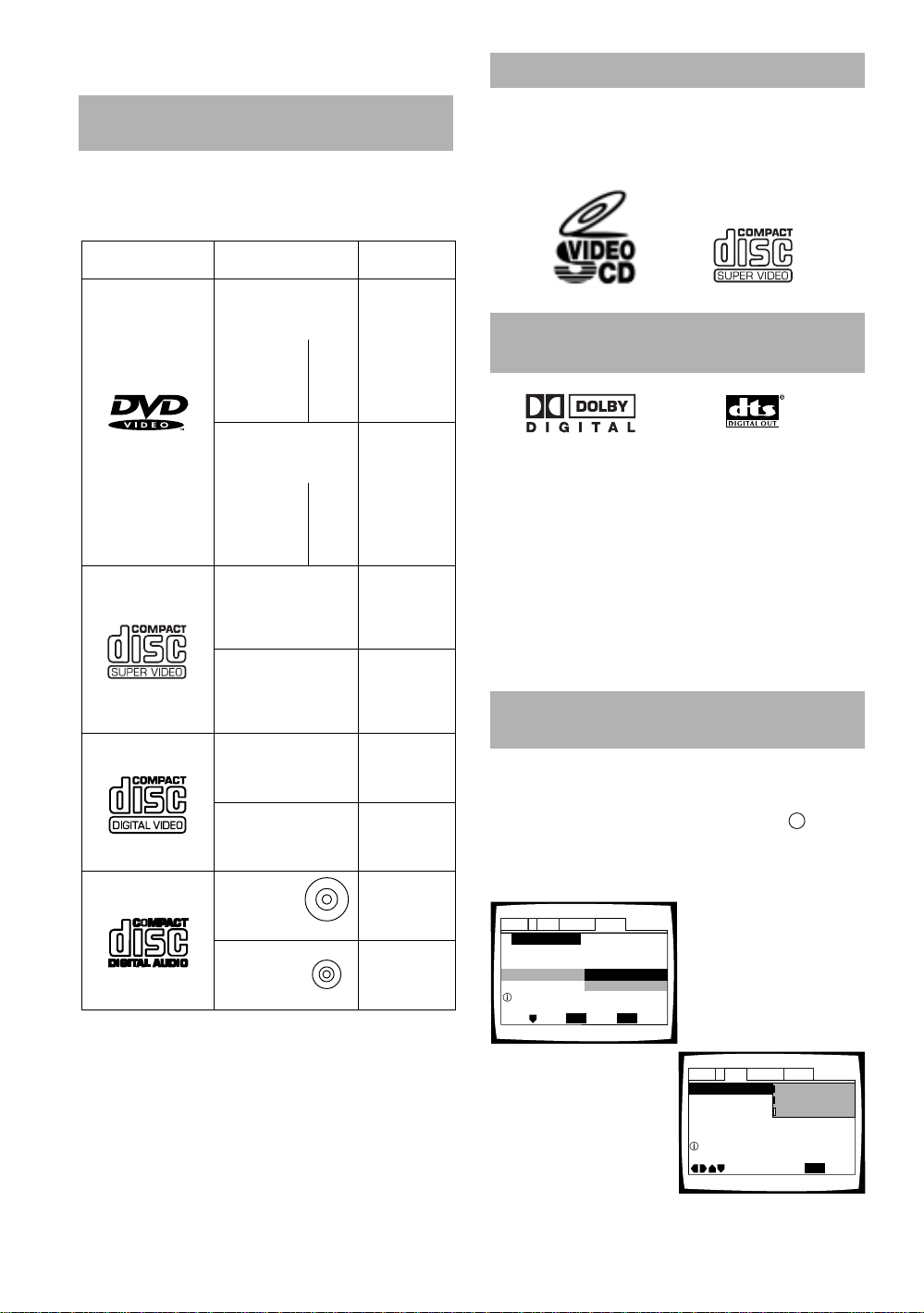
Compatible with DVD, Super VCD,
Video CD and CD formats
DVD, Super VCD (IEC standard), Video CD and CD discs
that display the logos shown below can be played back
on this DVD player. For more information on discs
compatible with this player, refer to the table below.
What is Super VCD ?
This player supports the IEC’s Super VCD standard.
Compared to the Video CD standard, Super VCD offers
superior picture quality, and allows two stereo
soundtracks to be recorded. Super VCD also supports
the widescreen size.
Types of playable
discs and their marks
DVD VIDEO
SUPER VCD
VIDEO CD
CD
Diameter/
Playable sides
DVD VIDEO
12 cm (5 in.)/
single-sided
12 cm (5 in.)/
double-sided
DVD VIDEO
8 cm (3 in.)/
single-sided
8 cm (3 in.)/
double-sided
SUPER VCD
12 cm (5 in.)/
single-sided
SUPER VCD single
8 cm (3 in.)/
single-sided
VIDEO CD
12 cm (5 in.)/
single-sided
VIDEO CD single
8 cm (3 in.)/
single-sided
CD
12 cm (5 in.)/
single-sided
CD single
8 cm (3 in.)/
single-sided
1 layer
2 layer
1 layer
2 layer
1 layer
2 layer
1 layer
2 layer
Playback time
Digital audio
Digital video
(MPEG 2)
133 min.
242 min.
266 min.
484 min.
Digital audio
Digital video
(MPEG 2)
41 min.
75 min.
82 min.
150 min.
Digital audio
(MPEG 1)
Digital video
(MPEG 2)
40 min.
Digital audio
(MPEG 1)
Digital video
(MPEG 2)
10 min.
Digital audio
Digital video
(MPEG 1)
Max. 74 min.
Digital audio
Digital video
(MPEG 1)
Max. 20 min.
Digital audio
Max. 74 min.
Digital audio
Max. 20 min.
The disc format logos shown above are found on disc
labels or on disc jackets.
• To prevent malfunction, do not use an 8 cm (3 in.)
adaptor (for CDs).
• Discs other than the ones indicated above cannot be
played on this unit.
• DVDs that have incompatible region numbers, DVDAudio, DVD-ROM, and CD-ROM cannot be played on
this unit. The region number of the player can be
found on the rear panel.
Compatible with a wide range of
DVD digital audio output formats
DVDs are recorded in one of four types of digital audio
formats (as of October 1998). The digital audio output
jacks of this player output Dolby Digital*, DTS**, MPEG,
and linear PCM digital bitstreams.
This player has a function that converts Dolby Digital and
MPEG audio formats into the linear PCM format. This
allows playback of DVDs recorded in Dolby Digital and
MPEG without the need for a decoder.
* Manufactured under license from Dolby Laboratories.
“Dolby”, “AC-3” and the double-D symbol are trademarks of
Dolby Laboratories. Confidential unpublished works, ©
1992–1997 Dolby Laboratories. All rights reserved.
** “DTS” is a trademark of Digital Theater Systems, Inc.
Easy setup and adjustment using
on-screen menus
Press SETUP on the remote control to open the Setup
screen and you’ll find setting up the system easy to do
with on-screen menus conveniently organized and
arranged. Additionally, on-screen information
appears to clarify the functions and explain the options
available. Below are just a few examples.
Audio1 GeneralLanguageVideo2
Setup Navigator
Setup Navigator
Setting up using the Setup Navigator
Select the type of TV screen
you are using and the
preferred screen format
you’d like to use when
watching DVDs in the Video
menu (page 29).
Move
ENTER
Start
Not Used
Select
SETUP
Exit
Answer a few questions and
have all the necessary audio,
video, and on-screen
language adjustments set
automatically by the player
using the Setup Navigator
(page 19).
i
4
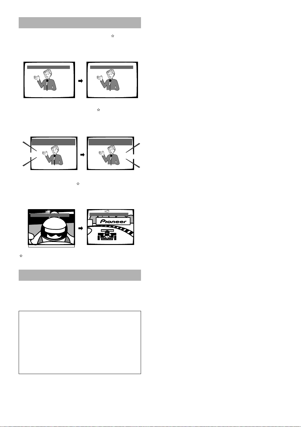
Wide range of DVD viewing options
Multi-Language Subtitles (page 37)
You can select a subtitle language or turn subtitles off
when watching movies or other media with subtitles
available.
Subtitle :1 English Subtitle :2 Spanish
HELLO!
HOLA!
Multiple Languages (page 38)
You can select the language on when watching movies
or other media that have multiple language and/or audio
soundtracks recorded on them.
Dolby Digital
5.1CH
HOLA
HELLO
Audio : 1 English
Dolby Digital
5.1CH
Audio : 2 Spanish
Multi-Angle (page 45)
You can view scenes from different camera angles when
watching movies or other media with multiple angle
playback available.
ANGLE : 2/4
This mark indicates this may not be possible with certain discs.
ANGLE : 3/4
Energy-saving design
This unit is designed to use minimal electricity when this
player is in standby mode. Regarding the amount of
power consumed in standby mode, refer to
“Specifications” on page 60 (backcover).
This product incorporates copyright protection
technology that is protected by method claims of
certain U.S. patents and other intellectual property
rights owned by Macrovision Corporation and other
rights owners. Use of this copyright protection
technology must be Authorized by Macrovision
Corporation, and is intended for home and other
limited viewing uses only unless otherwise authorized
by Macrovision corporation. Reverse engineering or
disassembly is prohibited.
5
Differences in Disc
How to Proceed in This
Composition
DVD
DVDs are divided into units referred to as titles, and
titles are divided into chapters. A DVD which contains a
movie may have only one title with many or no chapter
divisions. Karaoke DVDs may have many titles, assigning
a title to each song on the disc. Menu screens do not
belong to any title.
DVD player functions generally apply to titles on a disc or
chapters within a selected title. The player functions
available may also vary from title to title, depending on
the disc. When discs have a unique title division, it
should be noted that search and program functions may
be affected.
Title 1
Chapter 1 Chapter 2
DVD
Chapter 1 Chapter 2
Title 2
Manual
DVD is an incredible format that presents the highest
quality digital audio and video available today.
Because using the DVD player and DVDs may be
confusing at first, following the order below should help
you get through the important stages of getting set up
so you can start using your player as soon as possible.
Get familiar with the player.
Refer to the section “Before Using” on page 8 to
confirm that all the accessories were included with the
player. If you are new to DVD, it might be beneficial for
you to go through the “Names and Functions” section
starting on page 10 to get familiar with the parts and
buttons on the main unit and remote control as they will
be referred to throughout this manual.
There is also a list of terms that can be found on page 58
if you are having trouble understanding some of the
terminology associated with DVD.
Make the necessary connections.
No entertainment system seems to be set up exactly
the same way. The “Making Connections” section
starting on page 16 shows how video and audio
connections may be made to suit your home
entertainment system.
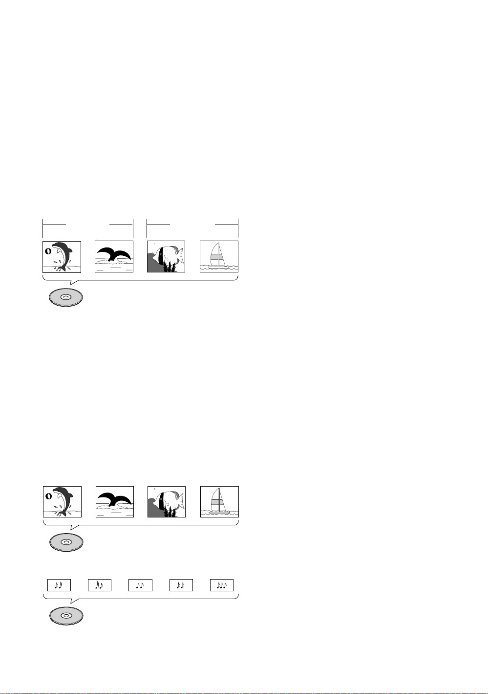
Super VCD/Video CD/CD
Super VCDs, Video CDs and CDs are divided into units
referred to as tracks (Super VCDs and Video CD tracks
may also be referred to as scenes). One song generally
corresponds to one track. Some tracks are further
divided into units referred to as indexes. Super VCDs/
Video CDs with PBC (Playback Control) also contain
menus recorded on the disc which enable easy access
to the contents of the disc.
When played back on a DVD player, Super VCDs, Video
CDs and CDs are considered to be a single title,
regardless of the number of tracks.
Track 1 Track 2 Track 3 Track 4
Super VCD/Video CD
Track 1 Track 2
CD
Track 3 Track 4 Track 5
Set up the player.
Before you can begin to enjoy the benefits of the DVD
format, you should set up the player to output the video
and audio information that corresponds to your system.
The section “Setting Up the Player” starting on page 19
explains how to use the Setup Navigator, a function that
automatically sets up the player corresponding to the
answers given in a multiple-choice on-screen procedure.
The Setup screen menus, described in the section
starting on page 26, are also used in a number of other
functions. Learning the procedure for operating the
menus will make using this player much easier and more
enjoyable.
Play a disc.
When all the connections and setups have been made,
you are ready to play a DVD, Super VCD/Video CD, or CD
with the player. The section “Getting Started Using Your
DVD Player” starting on page 22 outlines the basic
player operations.
Enjoy the many features available.
Once you are comfortable using the basic player
functions, you are ready to take advantage of the various
options DVD and this player have to offer. The section
“Advanced Functions” starting on page 42 describes
how to use the features available on many DVDs.
6

Table of Contents
Before Using ........................................ 8
Checking Accessories .....................................8
Preparing the Remote Control.........................8
Names and Functions ....................... 10
Front Panel ....................................................10
Display Window.............................................12
Rear Panel .....................................................13
Remote Control .............................................14
Making Connections ......................... 16
Connecting Your DVD Player .........................16
Audio Connections ........................................17
Video Connections.........................................18
System Control Connections.........................18
Setting Up the Player ....................... 19
Using the Setup Navigator.............................19
Getting Started Using Your DVD
Player..................................................22
Playing DVDs, Super VCDs, Video CDs and
CDs ..........................................................22
Improving Picture Quality ..............................23
Chapter (Track) Skip Forward/Skip Back ........24
Forward and Reverse Scanning.....................24
Stopping Playback and Switching
Power Off ................................................25
Adjusting Audio and Video
Settings.............................................. 26
Using the Setup Screen Menus ....................26
Changing the Setup Screen to “Expert” Menu
Mode........................................................27
Setting the Digital Audio Output To Be
Compatible with Your AV Components....28
Setting the TV Screen Size ............................29
Adjusting the OSD (On-Screen Display) ........30
Setting the Language Options......... 37
Selecting a Subtitle Language
(Multi-Language Subtitles) .......................37
Changing the Audio Language
(Multi-Language Function) .......................38
Setting Language and Subtitle Preferences
in the Setup Screen Menus .....................39
Advanced Functions ......................... 42
Adjusting the Dynamic Range of the
Audio Soundtrack.....................................42
Selecting Picture Quality Appropriate for
Program Content......................................42
Still Frame/Slow Play/
Frame Advance Playback .........................43
Searching for a Title, Chapter, Track,
or Location on a Disc ...............................44
Viewing from a Desired Camera Angle
(Multi-Angle).............................................45
Changing to Surround....................................45
Repeat Play....................................................46
Setting the Parental Lock Level.....................47
Continuing Playback from a
Specified Location (Last Memory) ...........49
Memorizing Settings for Often
Viewed DVDs (Condition Memory) ..........50
Viewing Disc Information ..............................51
Changing the Background Color
of the Screen ...........................................52
Resetting the Player to System Settings.......52
Additional Information ..................... 53
Disc Care .......................................................53
For Proper and Long Use of This Unit ...........54
Language Code List.......................................55
Troubleshooting .............................................56
Terms.............................................................58
Specifications ...................................Backcover
Karaoke Operation ............................ 31
Karaoke Entertainment ..................................31
Adjusting to Create the Desired Sound .........32
One-Touch Karaoke .......................................33
Reserving a Desired Song .............................33
Making Settings on the Karaoke
Setup Menu .............................................34
7
Before Using
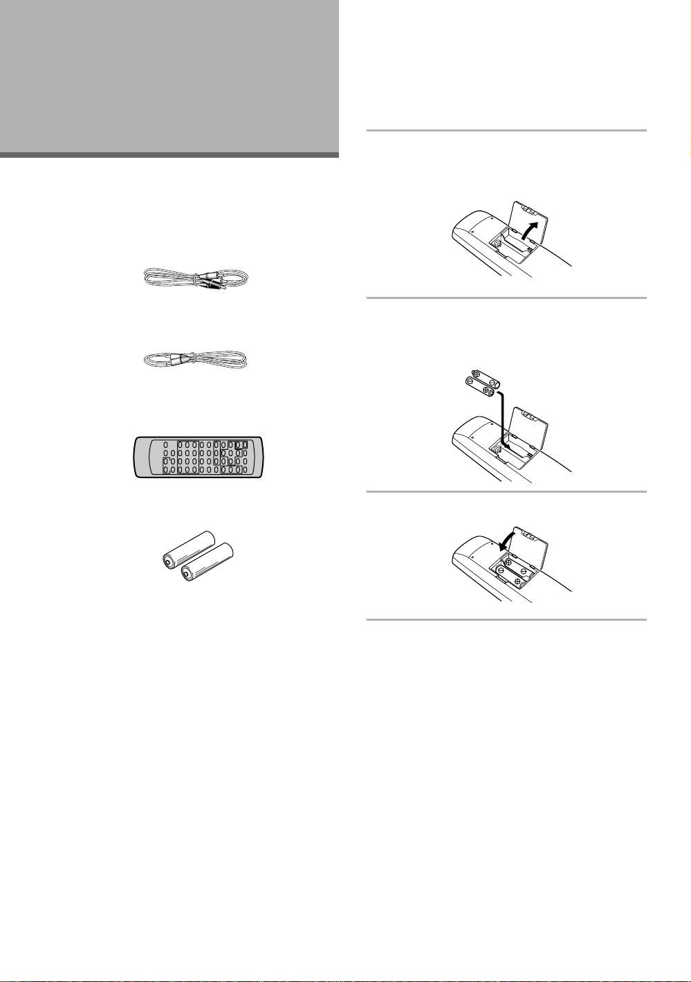
Checking Accessories
Please confirm that the following were received with
the player.
Audio cord
Preparing the Remote Control
Inserting batteries into the remote
control
1 While pushing the tab on the battery
compartment cover toward the center of the
remote, pull out in the direction indicated by
the arrow.
Video cord
Remote control unit
AA/R6P batteries
Power cord
Operating instructions (this manual)
2 Insert batteries.
Make sure to match the plus (+) and minus
(–) polarity guides on the batteries with the marks
inside the battery compartment.
3 Close the cover.
Notes
• Do not mix old and new batteries.
• When replacing batteries, use all new batteries.
• When not using the remote control for a long period of time
(over 1 month), remove the batteries to avoid possible damage
from battery corrosion. If battery leakage occurs, wipe the
battery liquid from the battery component, then insert new
batteries.
8

Remote control operation
When operating the remote control, point it at the
remote sensor (Î) located on the player’s front panel.
The remote control can be used up to 7 m from the
player and within a 30° angle on each side of the sensor.
30°
30°
23ft (7m)
Notes
• Exposing the remote sensor to direct sunlight or strong light
may cause faulty operation.
• If the CONTROL IN jack on the player’s rear panel is connected
to the CONTROL OUT jack of another component, point the
remote control at the other component to operate the player.
Operation will not be possible when pointed at this player
(page 18).
BEFORE USING
9
Names and
Functions
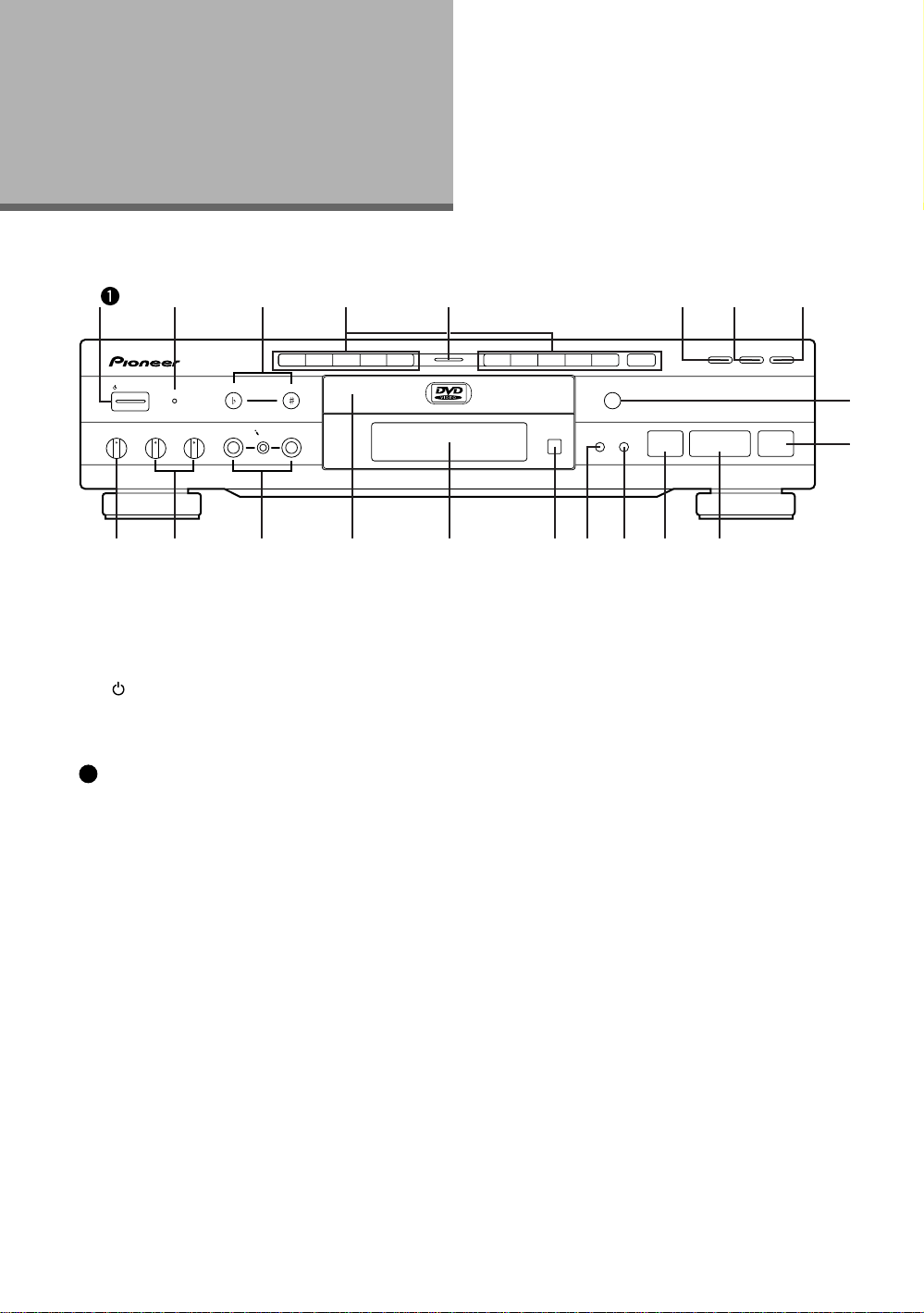
Front Panel
1
ECHO MIC 1 MIC 2 MIC 1 MIC 2
MIN MAX MIN MAX MIN MAX
2 3 4 6 7 8
1 2 3 4 5 6 7 8 9 0
KEY
MC
MIC CONTROL
STANDBY/ ON
STANDBY
DVD PLAYER
LOW CONTROL HIGH
1 [Models having a STANDBY/ON button on the
main unit]
STANDBY/ON button
Press to switch the player on or to put in standby
(page 22).
[Models having a POWER switch on the main
1
unit]
POWER switch
Press to switch the player on or off (pages 22 and
25).
When this switch is “ON”, the remote control can
be used to switch the player between the “ON”
state and standby.
2 STANDBY indicator
Indicates that the player is in standby, using a
minimum amount of power to maintain system
settings.
Turns off when the player is on.
5
PLAYBACK ONE-TOUCH KARAOKE
+
10
OPEN/CLOSE
0
Î
¡ ¢4 1
CONTROL KARAOKE MODE
ON/OFF
STOP
PLAY
78
3
-=~!@#$%^&
5 Disc illumination
Lights when a DVD is loaded and when no disc is
loaded. Turns off when a disc format other than DVD
is loaded in the player.
6 PLAYBACK CONTROL button and indicator
Use to switch the playback control for the Super
VCD/Video CD on or off. (page 23)
7 ONE-TOUCH KARAOKE button and indicator
Use to switch One-Touch Karaoke mode on or off.
(page 33)
8 KARAOKE MODE button and indicator
Use to switch between Karaoke mode and Normal
mode. (pages 22 and 31)
9 OPEN/CLOSE 0 button
Press to open and close the disc tray (pages 22 and
25).
PAUSE
9
0
3 KEY CONTROL buttons
Use to adjust the levels of the key in 11 steps.
(pages 32 and 36)
4 Number buttons (1-9, 0, +10)
Use to perform direct title and chapter/track
searches, and to input numerical values (pages 23
and 44).
10
0 PAUSE 8 button
Press during playback to pause. Press again to
resume playback (page 43).
- PLAY 3 button
Press to start or resume playback (pages 22 and 25).

= STOP 7 button
Press to stop playback. Pressing once enables
playback to resume from a point shortly before the
location where it stopped. Pressing twice causes the
disc to return to the beginning of the disc if playback
starts again. Resume play is possible only in Normal
mode (page 25).
~ ¡ ¢ (forward) button
Press to advance to chapters/tracks. Press and hold
to perform fast-forward scanning (page 24).
!/ 4 1 (reverse) button
Press to go back to previous chapters/tracks. Press
and hold to perform reverse playback scanning (page
24).
@ Remote sensor
Point the remote control toward the remote sensor
to operate the player (page 9).
# Display window
Displays system information (page 12).
$ Disc tray
When loading a disc, place a disc in the disc tray
with the label side facing up (pages 22 and 25).
% MIC1, MIC2 and MIC CONTROL jacks
Use to connect a microphone. (page 31)
^ MIC1 and MIC2 volume level knobs
Use to adjust the volume level of the microphone.
(page 31)
NAMES AND FUNCTIONS
& Digital Echo level knob
Use to adjust the echo level. (page 32)
11
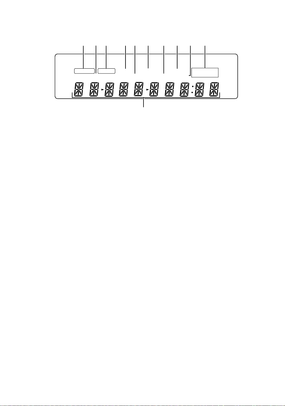
Display Window
2
3 4 6 75 8 091
96 kHz
TITLE
GUI
ANGLE
1 96 kHz indicator
Indicates play of a disc outputting an audio signal
with a sampling frequency of 96 kHz.
2 TITLE indicator
Indicates a title number is being displayed.
3 GUI indicator
ILights when the Karaoke or Setup on-screen menus
are being displayed (pages 19 and 26).
4 ANGLE indicator
Indicates Multi-Angle playback is in progress (page
45).
5 CHP/TRK indicator
Indicates a chapter or track number is being
displayed.
LAST MEMO CONDITION
CHP/TRK
-
7 REMAIN indicator
8 CONDITION indicator
9 TOTAL indicator
0 DOLBY DIGITAL indicator
- Counter display
DOLBY
REMAIN TOTAL
Indicates that the remaining playback time of a title
or chapter/track is being displayed.
Indicates that Condition Memory settings are
memorized for the currently loaded DVD (page 50).
Indicates that the disc in the player is stopped and
DISPLAY has been pressed (page 51).
Indicates Dolby Digital audio playback on DVDs.
Displays the playback mode, type of disc, title and
chapter/track numbers, playback time, etc.
DIGITAL
6 LAST MEMO indicator
Indicates the Last Memory location is recorded in
memory for the currently loaded DVD or Video CD
(page 49).
12
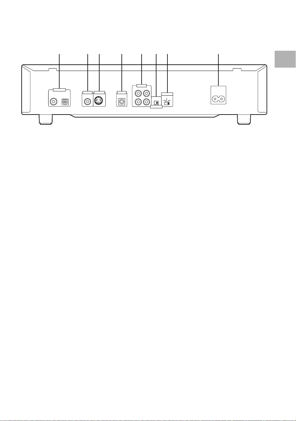
Rear Panel
1 2 3 4 5 6 7 8
DIGITAL OUT
NAMES AND FUNCTIONS
AUDIO OUT
OPT.
S-VIDEO OUT CONTROL
VIDEO OUT
RL
1
IN
2
ON OFF
ATTENUATOR
TV SYSTEM
NTSC
PAL
AUTO
AC IN
1 DIGITAL OUT jacks (coaxial, optical (OPT.))
Use to output the digital audio signal recorded on
discs. You can output the digital signal via either
coaxial or optical output jack to an AV amplifier or
receiver (page 17).
2 VIDEO OUT jack
Connect to the video input on a TV or monitor or AV
amplifier or receiver with video input capability
(page 18).
3 S-VIDEO OUT jack
If your TV or monitor has an S-video input, clear
picture reproduction is possible by connecting the
player to your TV or monitor via the S-video jack
(page 18).
4 CONTROL IN jack
Use to connect this player to another component
bearing the Pioneer Î mark. This lets you control
this unit as though it were a component in a system.
Player operations are then performed by pointing the
remote control at the component that the player is
connected to (page 18).
5 AUDIO OUT jacks
Use to output two-channel audio (analog) to the
audio stereo inputs on a TV or stereo amplifier. If you
are connecting to a receiver that has both digital and
analog input jacks for DVD player connection, it may
be beneficial to make both connections (page 17).
6 ATTENUATOR switch
Usually set to OFF. Switch it ON if the sound is
distorted when enjoying Karaoke (page 32).
7 TV SYSTEM switch
Use to change the TV signal mode to either PAL or
NTSC according to the type of TV and disc to be
used. When the switch is in the AUTO position, the
player outputs the format on the disc as is (page 18).
(The TV SYSTEM switch is not present on DVDV550.)
8 AC IN power cord connection terminal
Use to connect the power cord to the wall outlet
(page 16).
13
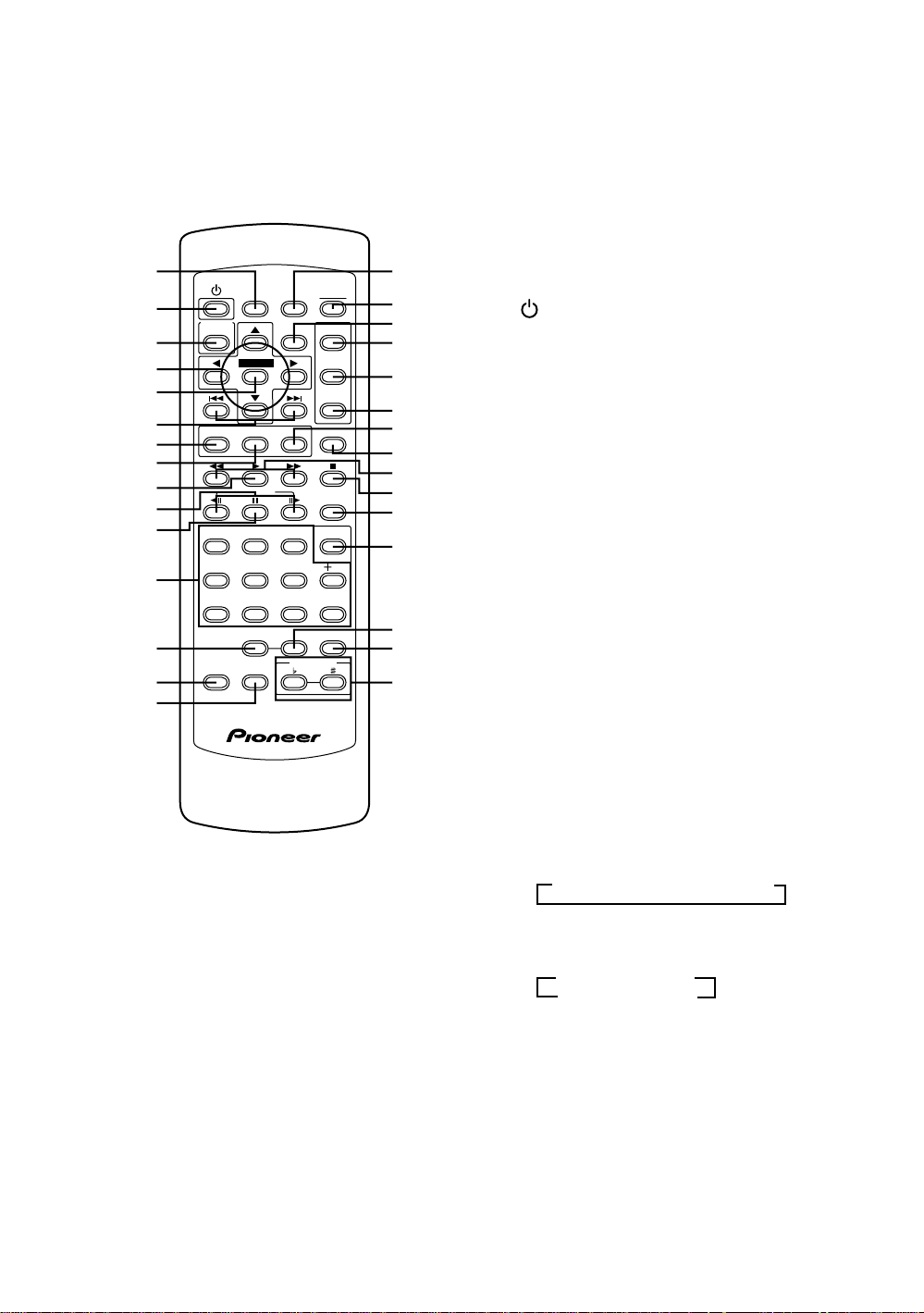
Remote Control
1
2
3
4
5
6
7
8
9
0
-
=
~
!
@
KARAOKE
SETUP
VNR
LAST
MEMORY
ENTER
STEP/SLOW
54
REPEAT A-B PROGRAM
PLAYBACK
CONTROL
OPEN/
CONDITION
CLOSE
MEMORY
DISPLAY SETUP
MENU
TOP MENU
RETURNANGLESUBTITLEAUDIO
SEARCH
MODE
CLEAR
321
610
9087
KEY CONTROL
(Buttons indicated with * are used for menu operation.)
1 LAST MEMORY button
You can resume DVD or Video CD playback from
the point you last watched even if the disc is
removed from the player. Press LAST MEMORY
during playback to set a Last Memory point. When
you want to resume playback of that disc, press
LAST MEMORY in the stop mode and playback
starts from the memorized point. Last Memory
locations can be stored for up to 5 DVDs and 1
#
$
%
^
&
*
(
Video CD (page 49).
2 (standby/on) button
Press to switch the player on or to put in standby
(pages 22 and 25).
3 KARAOKE SETUP button*
Press to open or close the Karaoke Setup screen
(page 34).
)
_
+
¡
4 Cursor buttons (2/3/5/∞)*
Use to move through the options on menu screens
and to change settings (pages 19, 23, 26, 27, 47 and
48).
™
5 ENTER button*
Use to implement settings selected with the cursor
buttons or to set items highlighted in a menu
£
(pages 19, 23 and 27).
¢
6 4 (previous)/¢ (next) buttons
∞
Î
During playback, press 4 to go back to a previous
chapter/track and ¢ to advance to the next
chapter/track (page 24).
14
7 AUDIO button
Press repeatedly to select one of the audio
languages and/or audio formats programmed on a
DVD (page 38).
For Video CD and CD in Normal mode, each press
changes the audio output as follows.
=
Stereo = 1/L (Left) = 2/R (Right)
For Super VCD, each press changes the audio
output as follows.
•Normal mode
=
1 Stereo = 1L = 1R
2R
+ 2L + 2 Stereo +
•Karaoke mode
1+= 2

8 SUBTITLE button
Press repeatedly to select one of the subtitle
languages programmed on a DVD or to turn the
subtitles off (page 37).
* TOP MENU button*
Press to call up the top menu programmed on the
DVD. Depending on the DVD, the top menu may be
identical to the DVD menu (page 23).
9 3 (play) button
Press to start disc playback (pages 22 and 25).
0 STEP/SLOW e/E buttons
Press STEP/SLOW E during playback to view
slow playback. In pause mode, press STEP/SLOW
E to advance DVDs and Super VCDs/Video CDs
frame by frame and STEP/SLOW e to back up a
few frames at a time. Reverse STEP/SLOW is not
possible with a Super VCD/Video CD (page 43).
- 8 (pause) button
Press to pause playback of a disc. Press again to
resume playback (page 43).
= Number buttons (1-9, 0, +10)*
Use to perform direct title and chapter/track
searches, and to input numerical values (pages 23
and 44).
~ REPEAT button
Press to repeat playback (page 46).
! VNR button
Press to turn on the video noise reduction function
(page 23).
@ PLAYBACK CONTROL button
Use to switch the playback control for the Super
VCD/Video CD on or off. (page 23)
# CONDITION MEMORY button
You can store in memory the settings for up to 15
DVDs. Press CONDITION MEMORY during DVD
playback to memorize the settings (page 50).
$ OPEN/CLOSE button
Press to open or close the disc tray (pages 22 and
25).
% DISPLAY button
Press during playback to display statistical disc
information. Press repeatedly to display different
information (page 51).
^ SETUP button*
Press when the player is in either play or stop mode
to open and close the Setup screen (page 26).
( ANGLE button
Some DVDs are recorded with various camera angle
playback options. Press ANGLE repeatedly to
display different camera angles (page 45).
) RETURN button*
Use to go one menu back (current settings are
maintained). Use RETURN when you do not want
to change the option setting in a menu (pages 23,
27, and 48).
_ 1 (fast reverse)/¡ (fast forward) buttons
During playback of DVD, Super VCD and Video CD,
press ¡ to perform fast forward scanning. Press
1 to perform fast reverse scanning of DVD, Super
VCD and Video CD. When a CD is loaded, audio
scanning is performed (page 24).
+ 7 (stop) button
Press to stop playback. In Normal mode, pressing
once enables playback to resume from a point
shortly before the location where it was stopped.
Pressing twice causes the disc to return to the
beginning of the disc when playback starts again.
Resume play is possible only in Normal mode
(page 25).
¡ SEARCH MODE button
Press to perform a title, chapter/track or time search
(page 44).
™ CLEAR button
Works in conjunction with a number of player
functions. Use to cancel repeat (page 46).
£ A-B button
Press at the beginning and end of the section you
want to repeat or to mark a location you want to
return to (page 46).
¢ PROGRAM button
You can use this button to program up to
24 subsequent tracks while you are singing.
(page 33)
∞ KEY CONTROL buttons
Use to adjust the levels of the key in 11 steps.
(pages 32 and 36)
NAMES AND FUNCTIONS
& MENU button*
Use to display or close the DVD menu screen
(page 23).
15
Making
Connections
Connecting Your DVD Player
Unlike any other audiovisual media format, DVD offers a
wide array of audio and video output options which
allows playback to be enjoyed in any number of system
configurations from a standard TV with stereo audio
input to a home theater system with a projection
monitor and full surround sound capabilities.
Connection Guide
The illustration on this page shows the basic setup using
the audio and video cords included with this player. Use
this illustration as a guide to setting up your home
system.
An explanation of each type of audio and video
connection available can be found on the following
pages. To determine the best audio and video
connection setup for your system, refer to the manuals
supplied with the components you are making
connections to.
In addition to making physical connections to your TV or
monitor, it is also necessary to assign the TV screen size.
You can use the [Setup Navigator] in the Setup screen
General menu to set whether you are using a wide
screen or standard size TV or monitor (page 20).
Additionally, you can use the [TV Screen] setting in the
Setup screen Video menu (page 29).
Notes
• When making connections to this unit or when changing
connections, check that the unit is in standby (off) by pressing
STANDBY/ON (POWER), and unplug the power cord from
the power outlet.
• The analog video output on this player uses copy protect
circuitry to prevent the video playback on DVDs from being
copied. If you connect the player to a TV via a VCR, or record
and play back the contents of a disc with a VCR, the playback
picture may not be normal.
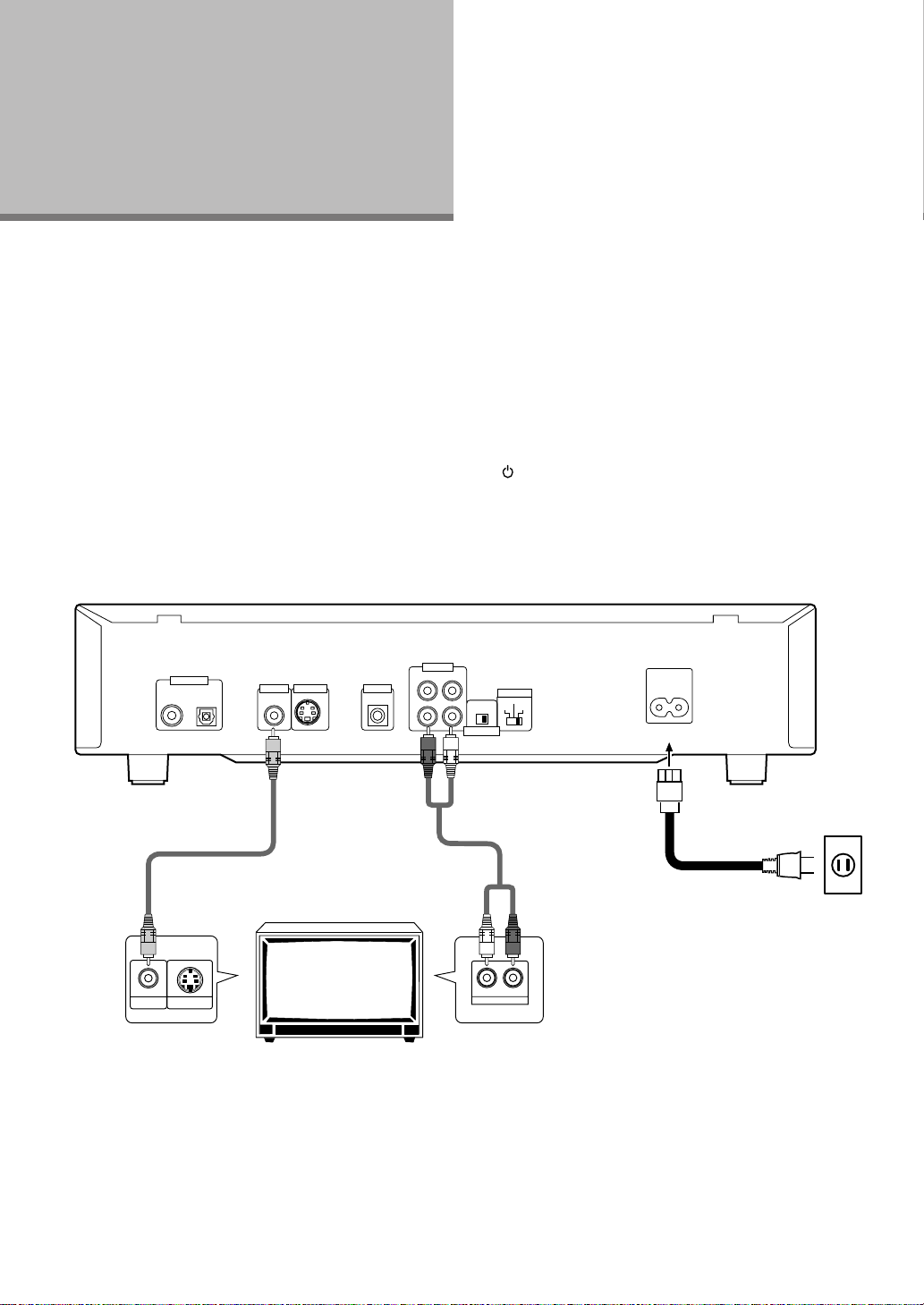
DIGITAL OUT
OPT.
Video cord
(Included)
VIDEO IN S-VIDEO IN
Make video connections from the VIDEO
OUT jack on the player to the VIDEO IN jack
on the TV or monitor using the video cord
included with the player.
S-VIDEO OUT CONTROL
VIDEO OUT
TV or monitor
AUDIO OUT
RL
1
IN
2
ON OFF
ATTENUATOR
TV SYSTEM
PAL
AUTO
NTSC
Audio cord
(Included)
RL
AUDIO IN
AC IN
DV-K102:
Finally, connect to a power outlet
(110–127 V, 220–240 V).
DVD-V550:
Finally, connect to a power outlet
(120 V).
Make audio connections from one of the
AUDIO OUT jacks on the player to the
AUDIO IN jacks on the TV or monitor using
the stereo audio cord included with the
player. Be sure to match the color of the
plugs with the color of the jacks (red and
white).
When music sounds distorted during
Karaoke, set the attenuator switch to the
ON position.
16
Audio Connections
This player features two digital (optical and coaxial) and
also analog 2 channel audio output connection
possibilities.
Digital Audio Connections:
You can enjoy the digital audio recorded on DVD discs
from both optical digital and coaxial digital output jacks.
When making digital audio connections, do not
make connections from both the coaxial and optical
digital outputs to the same component.
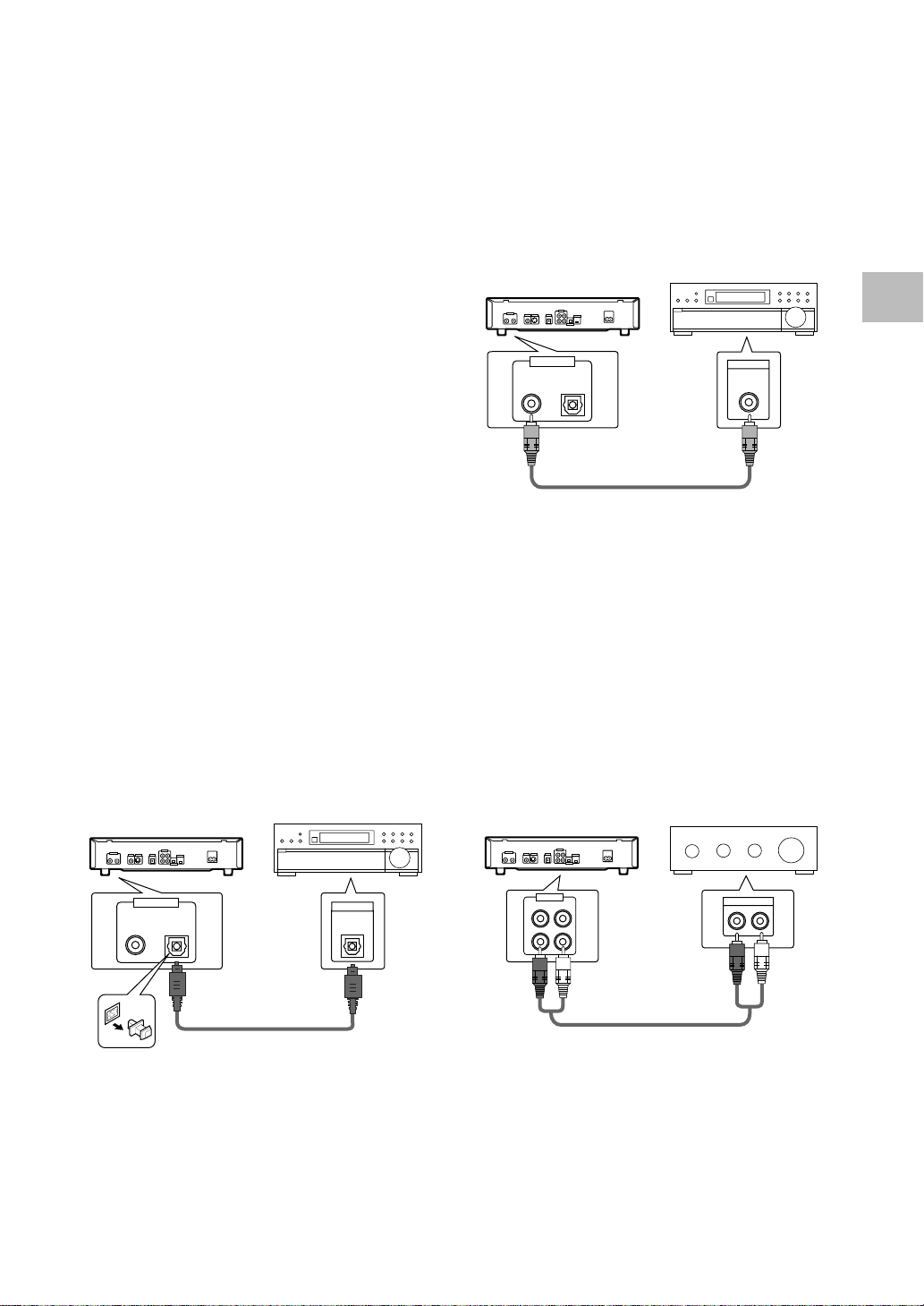
DIGITAL OUT (Coaxial)
The digital signal is transmitted electronically through a
coaxial cable.
• Use to connect to an AV amplifier or receiver with
built-in Dolby Digital, DTS, or MPEG decoder.
• Use a coaxial cable (not supplied) to connect the
coaxial digital output on the player to the coaxial digital
input on an AV amplifier or receiver.
AV amplifier or receiver with
built-in Dolby Digital, DTS, or
MPEG decoder
MAKING CONNECTIONS
When a DVD recorded in Dolby Digital, DTS, or MPEG is
loaded, noise will be output if you have made
connections via the digital audio jacks to a receiver or
amplifier that cannot decode a Dolby Digital, DTS, or
MPEG digital bitstream. In this case, be sure to set the
[Digital jack] setting in the Setup Navigator audio settings
to best reflect the type of system you are using
(page 21). Additionally, the digital audio settings can be
adjusted manually in the Setup screen Audio 1 menu
(page 26).
Note
There is no digital output when the player is set to Karaoke
mode.
DIGITAL OUT (Optical)
The digital signal is transmitted as light pulses through a
fiber-optic cable.
• Use to connect to an AV amplifier or receiver with
built-in Dolby Digital, DTS, or MPEG decoder.
• Use a fiber-optic cable (not supplied) to connect the
digital optical output on the player to the digital optical
input on an AV amplifier or receiver.
AV amplifier or receiver with
built-in Dolby Digital, DTS, or
MPEG decoder
DIGITAL OUT
OPT.
DIGITAL IN
Analog Audio Connection:
AUDIO OUT
• Make analog audio connections to a stereo amplifier
or receiver.
• Analog audio connections can also be made to a TV or
monitor with stereo input jacks.
• Use the supplied audio cable to connect one of the
AUDIO OUT analog jacks on the player to the audio
input on the stereo amplifier or receiver.
• When making analog audio connections, be sure to
match the color of the plugs with the color of the
jacks (red and white).
Stereo amplifier or receiver
DIGITAL OUT
AUDIO OUT
OPT.
DIGITAL IN
RL
1
2
AUDIO IN
RL
17
Video Connections
This player features S-video and composite video output
possibilities. Check the manual supplied with your TV or
monitor to determine the best possible connection for
your system.
In addition to making physical connections to your TV or
monitor, it is also necessary to assign the TV screen
size. You can use the [Setup Navigator] in the Setup
screen General to set whether you are using a wide
screen or standard size TV or monitor (page 20).
Additionally, you can use the [TV Screen] setting in the
Setup screen Video menu (page 29).
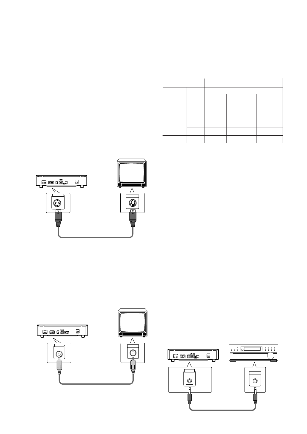
S-VIDEO OUT
• Make S-video connections to a TV or monitor with Svideo input to produce a high quality video image.
• Use an S-video cable (not supplied) to connect the
output on the player to S-video input on the TV or
monitor.
S-VIDEO OUT
TV or monitor
S-VIDEO IN
TV SYSTEM switch (except for DVD-V550)
Video output changes as follows according to the
playback disc‘s recorded format.
NTSC = PAL, PAL = NTSC conversion is possible on
Super VCDs/Video CDs. PAL = NTSC conversion is not
possible on DVDs. When the TV SYSTEM switch is set
to the AUTO position, the disc’s format will be output as
is. When a CD or disc is not loaded, the previous video
output format will be selected.
Disc Output format
Type
DVD
Super VCD/
Video CD
CD, No disc
Format
NTSC
PAL
NTSC
PAL
Position of TV SYSTEM switch
NTSC PAL AUTO
NTSC MOD. PAL NTSC
PAL PAL
NTSC MOD. PAL NTSC
NTSC PAL PAL
NTSC PAL NTSC or PAL
About MOD. (Modulation) PAL
• SHRINK
Most models of the newly developed countdown PAL
TV system detect 50 Hz (PAL)/60 Hz (NTSC) and
automatically switch vertical amplitude, resulting in a
display without vertical shrinkage.
• If your PAL TV does not have a V-Hold control, you
may not be able to view NTSC disc because the
picture may roll. If the TV has a V-Hold control, adjust
it until the picture stops rolling. On some TVs, the
picture may shrink vertically, leaving black bands at
the top and bottom of the screen. This is not a
malfunction; it is caused by the NTSC = PAL
conversion.
VIDEO OUT
• Make composite video connections to a standard TV
or monitor with a video input jack.
• Use the supplied video cable to connect the video
output jack on the player to the video input on the TV
or monitor.
• Be sure to match the color of the plug with the color
of the jack (yellow).
TV or monitor
VIDEO OUT
VIDEO IN
System Control Connections
Using a commercially available cord with a mini plug (3.5
mm dia. with no resistance) to connect this player’s
CONTROL IN jack to the CONTROL OUT jack of another
PIONEER component bearing the Î mark, you can
control the player as though it were a component in a
system (system control).
• If you connect for system control, you cannot operate
the player directly. Point the remote control unit at the
component (AV amplifier, etc.) connected to the
CONTROL OUT jack to operate.
• When controlling as a system, be sure to make a
connection to the amplifier using an audio or video
cord, even when using only digital components.
• For details, refer to the operation manuals of the
connected components.
CONTROL
IN
Pioneer component
with Î mark.
CONTROL
OUT
18
 Loading...