


ORDER NO.
RRV2468
COMPACT DISC PLAYER
CDJ-1000
THIS MANUAL IS APPLICABLE TO THE FOLLOWING MODEL(S) AND TYPE(S).
Type |
Model |
Power Requirement |
Remarks |
|
|
||||
CDJ-1000 |
||||
|
|
|
||
|
|
|
|
|
KUC |
O |
AC120V |
|
|
|
|
|
|
|
TL |
O |
AC110240V |
|
|
|
|
|
|
|
WY |
O |
AC220240V |
|
|
|
|
|
|
CONTENTS
1. |
SAFETY INFORMATION ....................................... |
2 |
7.1 DIAGNOSIS ................................................... |
59 |
|||
2. |
EXPLODED VIEWS AND PARTS LIST ................. |
4 |
7.1.1 SERVICE MODE .................................. |
59 |
|||
3. BLOCK DIAGRAM AND SCHEMATIC DIAGRAM 12 |
7.1.2 ERROR DISPLAY |
................................. |
61 |
||||
|
|
||||||
4. |
PCB CONNECTION DIAGRAM ........................... |
38 |
7.1.3 DISASSEMBLY ..................................... |
62 |
|||
5. |
PCB PARTS LIST ................................................ 52 |
7.1.4 PART REPLACEMENT METHOD OF JOG |
|||||
6. |
ADJUSTMENT ..................................................... |
57 |
SECTION ............................................... |
66 |
|||
7. GENERAL INFORMATION .................................. |
59 |
7.1.5 ABOUT ELECTRIC DISCHARGE .......... |
69 |
||||
|
|
|
7.1.6 SEQUENCE AFTER THE POWER ON . 70 |
||||
|
|
|
7.2 PARTS |
.......................................................... |
71 |
||
|
|
|
|
|
|
||
|
|
|
7.2.1 IC |
........................................................... |
71 |
||
|
|
|
|
|
|
||
|
|
|
8. PANEL FACILITIES AND SPECIFICATIONS |
....... |
87 |
||
|
|
|
|
||||
PIONEER ELECTRONIC CORPORATION 4-1, Meguro 1-chome, Meguro-ku, Tokyo 153-8654, Japan PIONEER ELECTRONICS SERVICE, INC. P.O. Box 1760, Long Beach, CA 90801-1760, U.S.A.
PIONEER ELECTRONIC NV Haven 1087, Keetberglaan 1, 9120 Melsele, Belgium
PIONEER ELECTRONICS ASIACENTRE PTE. LTD. 253 Alexandra Road, #04-01, Singapore 159936 c PIONEER ELECTRONIC CORPORATION 2001
T – ZZY JULY 2001 Printed in Japan
CDJ-1000
1. SAFETY INFORMATION
This service manual is intended for qualified service technicians; it is not meant for the casual do-it-yourselfer. Qualified technicians have the necessary test equipment and tools, and have been trained to properly and safely repair complex products such as those covered by this manual.
Improperly performed repairs can adversely affect the safety and reliability of the product and may void the warranty. If you are not qualified to perform the repair of this product properly and safely, you should not risk trying to do so and refer the repair to a qualified service technician.
WARNING
This product contains lead in solder and certain electrical parts contain chemicals which are known to the state of California to
cause cancer, birth defects or other reproductive harm.
Health & Safety Code Section 25249.6 – Proposition 65
NOTICE
(FOR CANADIAN MODEL ONLY)
Fuse symbols 
 (fast operating fuse) and/or
  (slow operating fuse) on PCB indicate that replacement parts must be of identical designation.
REMARQUE
(POUR MODÈLE CANADIEN SEULEMENT)
Les symboles de fusible 


 (fusible de type rapide) et/ou

 (fusible de type lent) sur CCI indiquent que les pièces de remplacement doivent avoir la même désignation.
(FOR USA MODEL ONLY)
1. SAFETY PRECAUTIONS
The following check should be performed for the continued protection of the customer and service technician.
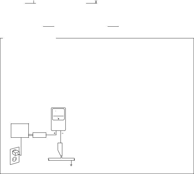
LEAKAGE CURRENT CHECK
Measure leakage current to a known earth ground (water pipe, conduit, etc.) by connecting a leakage current tester such as Simpson Model 229 - 2 or equivalent between the earth ground and all exposed metal parts of the appliance (input/output terminals, screwheads, metal overlays, control shaft, etc.). Plug the AC line cord of the appliance directly into a 120V AC 60 Hz outlet and turn the AC power switch on. Any current measured must not exceed 0.5 mA.
|
Reading should |
|
not be above |
|
Leakage 0.5 mA |
Device |
current |
tester |
|
under |
|
test |
|
|
Test all exposed |
|
metal surfaces |
Also test with plug reversed
(Using AC adapter plug as required)
Earth ground
AC Leakage Test
ANY MEASUREMENTS NOT WITHIN THE LIMITS OUTLINED ABOVE ARE INDICATIVE OF A POTENTIAL SHOCK HAZARD AND MUST BE CORRECTED BEFORE RETURNING THE APPLIANCE TO THE CUSTOMER.
2. PRODUCT SAFETY NOTICE
Many electrical and mechanical parts in the appliance have special safety related characteristics. These are often not evident from visual inspection nor the protection afforded by them necessarily can be obtained by using replacement components rated for voltage, wattage , etc. Replacement parts which have these special safety characteristics are identified in this Service Manual.
Electrical components having such features are identified by marking with a  on the schematics and on the parts list in this Service Manual.
The use of a substitute replacement component which does not have the same safety characteristics as the PIONEER recommended replacement one, shown in the parts list in this Service Manual, may create shock, fire, or other hazards.
Product Safety is continuously under review and new instructions are issued from time to time. For the latest information, always consult the current PIONEER Service Manual. A subscription to, or additional copies of, PIONEER Service Manual may be obtained at a nominal charge from PIONEER.
2
CDJ-1000
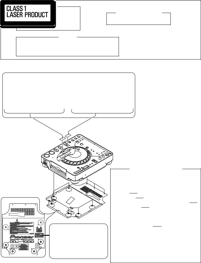
IMPORTANT
THIS PIONEER APPARATUS CONTAINS LASER OF CLASS 1.
SERVICING OPERATION OF THE APPARATUS S H O U L D B E D O N E B Y A S P E C I A L L Y INSTRUCTED PERSON.
WARNING !
LASER DIODE CHARACTERISTICS
MAXIMUM OUTPUT POWER: 5 mW
WAVELENGTH: 780 – 785 nm
The AEL(accessible emission level) of the laser power output is less then CLASS 1 but the laser component is capable of emitting radiation exceeding the limit for
CLASS 1.
A specially instructed person should servicing operation of the apparatus.
LABEL CHECK (for CDJ-1000/ TL and WY types)
CDJ-1000/ TL and WY Types Only
Bottom Plate
Printed on the Bottom Plate
Additional Laser Caution
1.Laser Interlock Mechanism
The position of the switch (S1) for detecting loading completion is detected by the system microprocessor, and the design prevents laser diode oscillation when the switch is not in LPS1 terminal side (when the mechanism is not clamped and LPS1 signal is high level.) Thus, the interlock will no longer function if the switch is deliberately set to LPS1
terminal side. ( if LPS1 signal is low level ).
In the test mode the interlock mechanism will not function. Laser diode oscillation will continue, if pin 33 of CXA1782CQ (IC101) on the MOTHER BOARD ASSY is connected to GND, or pin 43 of IC701 (LDON) is connected to low level (ON), or else the terminals of Q101 are shorted to each other (fault condition).
2.When the cover is opened, close viewing of the objective lens with the naked eye will cause exposure to a Class 1 laser beam.
: Refer to page 57.
3
CDJ-1000
2. EXPLODED VIEWS AND PARTS LIST
∙
∙The  mark found on some component parts indicates the importance of the safety factor of the part.
Therefore, when replacing, be sure to use parts of identical designation.
∙Screws adjacent to  mark on the product are used for disassembly.
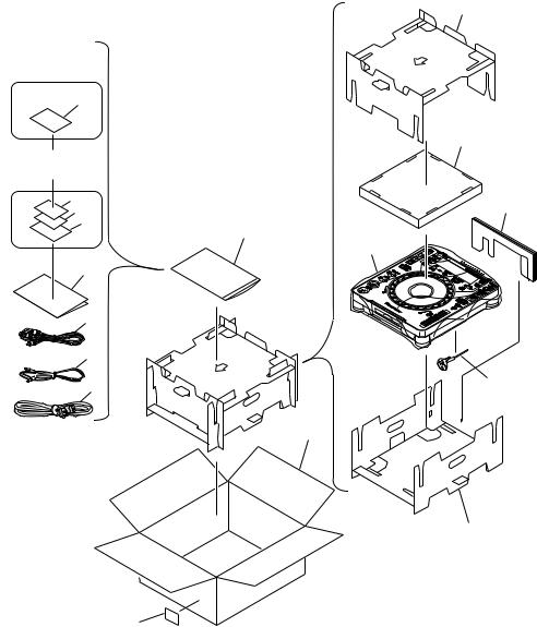
2.1PACKINGParts marked by "NSP" are generally unavailable because they are not in our Master Spare Parts List.NOTES:
|
9 |
|
KUC Type |
|
|
Only |
|
|
2 |
|
|
|
10 |
|
WY Type |
|
|
Only |
|
|
16 |
11 |
|
17 |
||
|
||
14 |
7 |
|
|
||
|
13 |
|
4 |
|
6
5
1 |
3 |
12
8
15
4

CDJ-1000
(1) PACKING PARTS LIST
Mark |
No. |
Description |
|
Part No. |
|
1 |
Power Cord |
|
See Contrast table (2) |
NSP |
2 |
Warranty Card |
|
See Contrast table (2) |
|
3 |
Forced Eject Pin |
|
DEX1013 |
|
4 |
Operating Instructions |
|
See Contrast table (2) |
|
5 |
Control Cord (L= 1m) |
|
PDE1247 |
|
6 |
Audio Cable (L = 1.5m) |
|
VDE1033 |
NSP |
7 |
Polyethylene Bag |
|
Z21-038 |
|
|
(0.03 × 230 × 340) |
|
|
|
8 |
Pad (A) |
|
DHA1518 |
|
9 |
Pad (B) |
|
DHA1519 |
|
10 |
Pad (C) |
|
DHA1523 |
|
11 |
Pad (D) |
|
DHA1524 |
|
12 |
Packing Case |
|
See Contrast table (2) |
|
13 |
Sheet |
|
RHX1006 |
NSP |
14 |
Mini Catalogue |
|
See Contrast table (2) |
NSP |
15 |
Label |
|
See Contrast table (2) |
NSP |
16 |
Pamphlet |
|
See Contrast table (2) |
NSP |
17 |
MMC Catalog |
|
See Contrast table (2) |
(2) CONTRAST TABLE
CDJ-1000/KUC, TL and WY types are constructed the same except for the following :
Mark |
No. |
Symbol and Description |
|
Part No. |
|
Remarks |
|
|
|
|
|||||
KUC Type |
TL Type |
WY Type |
|||||
|
|
|
|
||||
|
|
|
|
|
|
|
|
|
1 |
Power Cord |
ADG7021 |
ADG1154 |
ADG1154 |
|
|
NSP |
2 |
Warranty Card |
ARY7043 |
Not used |
Not used |
|
|
|
4 |
Operating Instructions (English) |
DRB1297 |
Not used |
Not used |
|
|
|
4 |
Operating Instructions (English/ Spanish) |
Not used |
DRB1299 |
Not used |
|
|
|
4 |
Operating Instructions (English/ French |
Not used |
Not used |
DRB1298 |
|
|
|
|
/German/ Italian/ Dutch/ Spanish) |
|
|
|
|
|
|
12 |
Packing Case |
DHG2145 |
DHG2146 |
DHG2129 |
|
|
NSP |
14 |
Mini Catalogue |
Not used |
Not used |
DRY1194 |
|
|
NSP |
15 |
Label |
VRW1629 |
Not used |
Not used |
|
|
NSP |
16 |
Pamphlet |
Not used |
Not used |
DRY1188 |
|
|
NSP |
17 |
MMC Catalog |
Not used |
Not used |
DRY1195 |
|
|
|
|
|
|
|
|
|
5
CDJ-1000
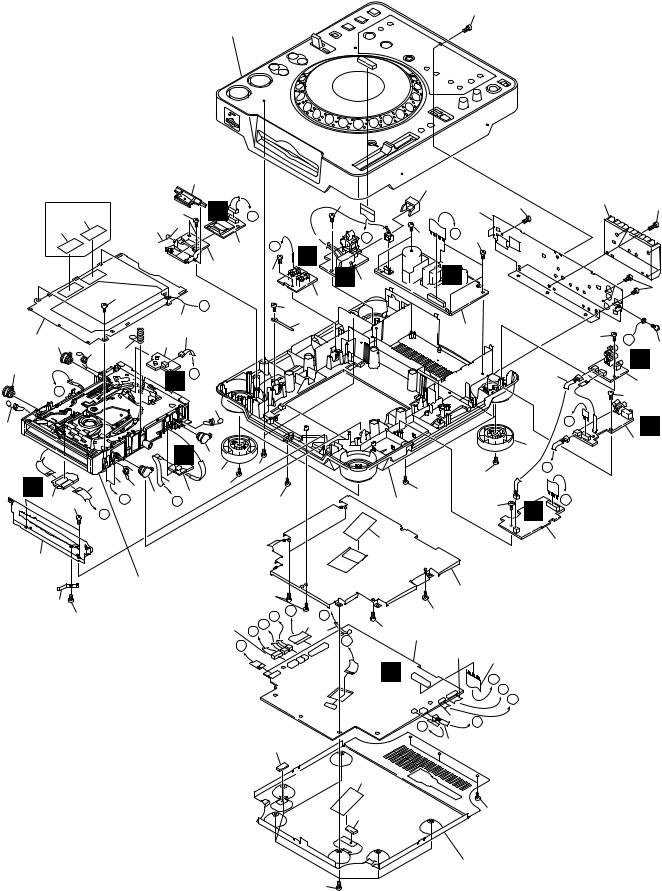
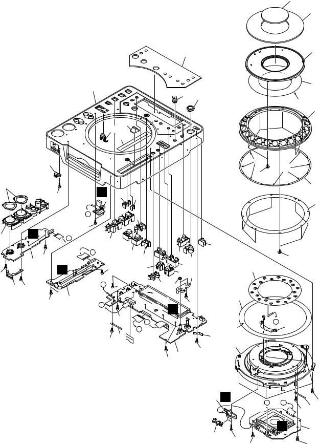
2.2 EXTERIOR (1/2) SECTION
48
Refer to
"2.3 EXTERIOR (2/2) SECTION".
|
TL and WY Type |
|
|
40 |
|
|
|
|
|
|
30 |
|
|
|
|
|
|
|
||
|
|
|
|
|
|
|
|
|
|
|
|
|
|
|
|
|
|
|||
|
Only |
|
|
|
|
F |
|
|
|
|
47 |
|
|
|
|
47 |
|
29 |
|
49 |
|
|
|
|
|
|
|
|
|
|
|
|
|
28 |
|
|
|||||
|
45 |
|
|
47 |
|
A |
|
|
|
|
|
|
|
|
|
|||||
|
|
|
|
|
|
|
|
|
|
|
|
|
|
|
|
|||||
|
|
|
|
|
|
|
|
|
|
|
|
|
|
|
|
|
||||
|
46 |
|
39 |
|
|
|
|
|
|
|
|
I |
47 |
C |
47 |
|
|
|
|
|
|
|
|
|
|
|
|
2 |
H |
|
|
|
|
|
|
|
|
||||
|
|
|
|
|
|
|
|
D |
|
|
|
|
|
|
|
|
|
|
||
|
|
|
|
|
|
38 |
|
|
|
Q |
|
|
P |
|
|
|
|
|
|
|
|
|
|
|
|
|
|
47 |
|
|
6 |
|
|
|
|
|
|
|
|||
|
|
|
|
|
|
|
|
|
|
|
|
|
|
|
|
|
||||
|
|
|
|
|
|
|
|
|
|
|
|
|
|
|
|
|
|
|
|
|
|
|
47 |
|
|
|
|
|
|
|
|
|
|
|
|
|
|
|
|
|
47 |
|
|
|
|
|
M |
|
|
|
|
10 |
|
|
|
|
|
|
|
|
|
|
|
|
|
|
|
|
|
|
47 |
|
|
|
|
|
|
|
|
|
|
||
|
|
|
|
15 |
|
|
|
32 |
|
|
|
|
|
|
|
|
|
|
||
|
|
|
|
|
|
|
|
|
|
|
|
11 |
|
|
|
|
|
|||
44 33 |
|
|
23 |
|
|
|
|
|
|
|
|
|
|
47 |
M |
|
||||
|
|
5 |
|
|
|
|
|
|
|
|
|
|
|
|
|
48 |
||||
|
|
|
|
|
|
|
|
|
|
|
|
|
|
|
|
|||||
|
25 |
26 |
|
|
|
|
|
|
|
|
|
|
|
|
|
|
|
|
H |
|
|
|
|
|
|
|
|
|
|
|
|
|
|
|
|
|
|
|
|
||
33 |
|
|
|
E J |
|
|
|
|
|
|
|
|
|
|
17 |
|
|
|
||
|
|
|
|
|
|
|
|
|
|
|
|
|
|
|
|
|
||||
|
K |
|
|
|
|
|
|
|
|
|
|
|
|
|
|
8 |
|
|||
|
|
|
|
|
|
|
|
|
|
|
|
|
|
|
|
|
|
47 |
|
|
|
|
|
|
|
|
25 |
|
|
|
|
|
|
|
|
|
|
|
|
|
|
|
|
|
|
|
|
|
|
|
|
|
|
|
|
|
|
|
|
|
|
|
25 |
|
|
|
|
|
|
|
|
|
|
|
|
|
|
|
|
E |
|
|
I |
|
|
|
|
|
|
|
|
|
|
|
|
|
|
|
|
|
|
9 |
||
|
|
|
|
C |
|
|
|
|
|
|
|
|
|
|
37 |
|
|
|
||
|
|
|
|
33 |
|
|
|
|
|
|
|
|
|
|
|
|
|
|||
|
|
|
|
47 |
|
|
|
|
|
|
|
|
B |
|
|
|
|
|||
|
|
|
|
|
|
37 |
|
|
|
|
|
|
|
47 |
|
|
|
|
||
B |
13 |
|
|
|
|
|
|
|
|
|
|
|
|
|
|
|
|
|
||
1825 |
|
14 |
|
47 |
|
|
|
|
|
|
47 |
|
|
|
|
|
|
|
||
|
33 |
4 |
|
|
|
|
|
|
|
|
|
|
|
|
|
|||||
|
3 47 |
G |
F |
|
|
47 |
|
|
|
27 |
|
|
47 |
G |
D |
|
|
|
||
|
|
|
|
|
|
|
|
|
|
|
|
|
||||||||
|
L |
|
|
|
|
|
|
|
|
|
|
|
|
|
|
|
|
|
|
|
|
|
|
|
|
|
|
|
|
|
|
|
36 |
|
|
|
7 |
|
|
|
|
31 |
|
|
|
|
|
|
|
|
|
|
|
|
|
|
|
|
|
|
|
|
|
|
Refer to |
|
|
|
|
|
|
|
|
|
|
35 |
|
|
|
|
|
||
|
34 |
"2.4 SLOT-IN MECHANISM |
47 |
|
|
|
|
|
|
|
|
|
|
|||||||
|
SECTION". |
|
|
|
K |
I |
|
H |
|
47 |
|
|
|
|
|
|
|
|||
|
48 |
|
|
|
|
|
|
12 |
|
|
|
|
|
|
|
|
||||
|
|
|
|
|
|
|
|
|
|
|
|
|
|
|
|
|||||
|
|
|
|
|
|
24 |
|
J |
|
|
|
|
|
|
|
|
|
|
|
|
|
|
|
|
|
|
A |
|
19 |
47 |
1 |
|
|
|
|
|
|
|
|||
|
|
|
|
|
|
|
|
|
|
|
|
|
|
|
||||||
|
|
|
|
|
|
|
|
|
|
|
|
|
|
|
|
|||||
|
|
|
|
|
|
|
L |
|
|
|
G |
|
|
21 |
|
|
|
|
|
|
|
|
|
|
|
|
|
|
|
|
|
|
|
|
|
|
|
|
|
||
|
|
|
|
|
|
|
|
|
|
|
|
|
|
22 |
|
|
|
|
|
|
|
|
|
|
|
|
|
|
|
|
|
|
A |
|
|
|
|
|
|
|
|
|
|
|
|
|
|
|
|
|
|
|
|
|
|
C |
|
|
|
|
|
|
|
|
|
|
|
|
|
|
|
|
|
|
|
|
|
D |
E |
|
|
|
|
|
|
|
|
|
|
|
|
|
|
|
|
|
|
|
|
|
|
|
|
|
|
|
|
|
|
|
|
|
|
|
|
|
|
F |
20 |
B |
|
|
|
|
|
|
|
|
|
|
|
|
|
|
|
|
|
|
|
|
|
|
|
|
|
|
|
|
|
|
|
|
|
|
41 |
|
|
|
|
|
16 |
|
|
|
|
|
|
|
|
|
|
|
|
|
|
|
|
|
|
43 |
|
|
|
|
|
|
|
|
|
|
|
|
|
|
|
|
|
|
|
|
41 |
|
|
48 |
|
|
|
|
|
|
|
|
|
|
|
|
|
|
|
|
|
|
|
42 |
|
|
|
|
|
|
|
|
|
|
|
|
|
|
|
|
48 |
|
|
|
|
|
|
|
|
|
|
6

CDJ-1000
(1) EXTERIOR (1/2) SECTION PARTS LIST
Mark No. |
Description |
|
Part No. |
Mark |
No. |
Description |
|
Part No. |
|
|
1 |
MAIN Assy |
|
DWX2161 |
|
26 |
Earth Spring |
|
DBH1398 |
2 |
MMCB Assy |
|
DWX2169 |
|
27 |
Chassis |
|
DNK3869 |
|
3 |
SPCN Assy |
|
DWX2170 |
NSP |
28 |
Rear Panel |
|
See Contrast table (2) |
|
4 |
STCN Assy |
|
DWX2171 |
|
29 |
Heat Sink |
|
DNG1081 |
|
5 |
SLMB Assy |
|
DWX1309 |
|
30 |
Power Knob |
|
DAC1895 |
|
6 |
PSWB Assy |
|
See Contrast table (2) |
|
31 |
Front Plate |
|
DNH2480 |
|
7 |
DABB Assy |
|
DWX2162 |
|
32 |
Cord Clamper |
|
RNH-184 |
|
8 |
JACB Assy |
|
DWX2163 |
|
33 |
Damper |
|
CNV6011 |
|
9 |
DOUT Assy |
|
DWX2164 |
|
34 |
Earth Plate (CU) |
|
VBK1070 |
|
10 |
FLRB Assy |
|
DWX2166 |
|
35 |
Shield Case |
|
DNH2481 |
|
11 |
SW POWER SUPPLY Assy |
|
DWR1344 |
|
36 |
Shield Cushion |
|
DEC2445 |
|
12 |
25P Flexible Cable/60V |
|
DDD1189 |
|
37 |
Insulator Assy |
|
DXA1904 |
|
13 |
12P Flexible Cable/60V |
|
DDD1190 |
|
38 |
Memory Holder |
|
DNK3884 |
|
14 |
4P Flexible Cable/60V |
|
DDD1191 |
|
39 |
Flap Spring |
|
DBH1487 |
|
15 |
Earth Lead Unit/300V |
|
DDF1015 |
|
40 |
SD Flap |
|
DNK3883 |
|
16 |
Connector Assy 3P |
|
DKP3546 |
NSP |
41 |
Silicone Rubber D5L |
|
DEB1456 |
|
17 |
Connector Assy 3P |
|
DKP3548 |
|
42 |
Bottom Plate |
|
DNH2479 |
|
18 |
FPC D5 Slot |
|
DNP1951 |
|
43 |
Bottom Cushion |
|
DEC2444 |
|
19 |
Jumper Wire 03P |
|
D20PYY0310E |
|
44 |
Mecha Plate |
|
DNH2339 |
|
20 |
Jumper Wire 05P |
|
D20PYY0510E |
|
45 |
Caution Label |
|
See Contrast table (2) |
|
21 |
Jumper Wire 09P |
|
D20PYY0910E |
NSP |
46 |
Caution Label HE |
|
See Contrast table (2) |
|
22 |
Jumper Wire 15P |
|
D20PYY1510E |
|
47 |
Screw |
|
BPZ30P080FZK |
|
23 |
Connector Assy |
|
PF03PP-B30 |
|
48 |
Screw |
|
BBZ30P060FZK |
|
24 |
Connector Assy |
|
PG07KK-F15 |
|
49 |
Screw |
|
BBZ30P120FZK |
|
25 |
Float Spring (G5) |
|
DBH1485 |
|
|
|
|
|
|
(2) CONTRAST TABLE
CDJ-1000/KUC, TL and WY types are constructed the same except for the following :
Mark |
No. |
Symbol and Description |
|
Part No. |
|
Remarks |
|
|
|
|
|||||
KUC Type |
TL Type |
WY Type |
|||||
|
|
|
|
||||
|
|
|
|
|
|
|
|
|
6 |
PSWB Assy |
DWS1312 |
DWS1311 |
DWS1311 |
|
|
NSP |
28 |
Rear Panel |
DNC1576 |
DNC1577 |
DNC1567 |
|
|
|
45 |
Caution Label |
Not used |
VRW1094 |
VRW1094 |
|
|
NSP |
46 |
Caution Label HE |
Not used |
VRW1297 |
VRW1297 |
|
|
|
|
|
|
|
|
|
7
CDJ-1000
2.3 EXTERIOR (2/2) SECTION |
17 |
|
16
|
|
|
|
|
|
|
|
|
42 |
|
|
|
8 |
|
|
|
|
|
|
|
|
|
|
|
|
|
|
|
|
|
|
|
20 |
|
|
|
|
|
|
|
7 (1/3) |
|
|
|
|
|
|
|
|
44 |
|
|
|
|
|
|
|
|
|
|
|
|
|
|
21 |
|
|
|
|
|
|
|
|
|
|
|
|
|
|
|
|
*1 |
|
|
|
|
|
|
|
|
|
|
|
|
|
|
|
|
|
|
|
|
|
|
|
|
|
|
|
|
9 |
|
|
|
|
|
|
43 |
|
|
|
|
|
|
|
|
|
|
|
|
25 (2/2) |
|
|
|
|
|
|
|
|
|
|
|
|
|
|
41 |
|
|
|
|
|
|
|
|
|
22 |
|
|
|
|
|
|
|
|
*1 |
*1 |
|
|
|
|
|
|
|
|
|
|
|
|
10 |
|
|
|
|
|
|
|
|
|
|
|
|
|
|
|
|
23 |
|
|
|
|
K |
|
|
|
|
|
|
|
7 (3/3) × 8 |
|
|
|
45 |
|
30 |
31 |
|
|
|
|
|
|
|
|
|
|
|
4 |
|
|
|
|
|
|
|||
|
|
|
|
|
|
|
|
|
|
|
|
11 |
|
|
|
|
|
|
|
|
|
|
|
|
|
|
|
|
|
|
|
|
E |
|
29 |
|
|
|
|
|
|
|
|
|
|
|
|
|
|
|
|
|
|
|
|
|
L |
|
|
|
45 |
|
|
|
|
|
|
|
|
24 |
|
|
C |
26 |
|
|
|
|
|
|
|
|
|
|
|
|
|
|
|
|
|
|
|
|
|||
|
|
|
|
|
|
|
|
|
37 |
|
|
|
|
|
|
|
|
|
|
|
|
|
|
|
|
|
|
|
|
45 |
|
|
D |
|
27 |
|
36 |
|
|
10 |
|
|
2 |
|
|
|
|
28 |
|
|
35 |
|
|
||
|
|
|
|
|
|
|
|
34 |
|
|
|
||
|
|
M |
|
|
|
25 (1/2) |
|
|
|
|
|
||
|
|
|
|
45 |
|
|
|
14 |
|
|
|||
45 |
|
|
|
|
|
33 |
18 |
|
|
||||
|
|
|
|
|
|
|
|
|
|
||||
40 45 |
|
|
|
|
E |
45 |
|
32 19 |
|
|
|
|
|
|
|
45 |
|
3 |
|
|
|
|
45 |
7 (2/3) |
|
|
|
|
|
|
|
C |
|
|
J |
|
|
|
|||
|
|
|
|
|
|
|
|
|
|
||||
|
|
|
|
|
|
|
|
|
|
|
|
|
|
|
|
|
|
|
|
45 |
D |
|
|
|
|
A |
|
|
|
|
|
|
|
|
|
|
|
|
|
||
|
|
|
|
|
|
|
B |
|
|
|
*1 |
13 |
|
|
|
|
|
|
|
|
|
|
|
|
|
||
|
|
|
|
|
45 |
39 |
|
|
|
38 |
|
|
|
|
|
|
|
|
|
|
|
|
|
|
|||
|
|
|
|
|
|
|
|
|
|
12 |
|
|
|
|
|
|
|
|
|
|
|
|
|
|
|
|
|
|
|
|
|
|
|
|
|
|
1 |
45 |
|
|
|
|
|
|
|
|
|
|
|
45 |
|
|
|
|
|
|
|
|
|
|
|
|
|
|
|
|
|
|
|
|
|
|
|
|
|
|
|
|
|
6 O |
B |
45 |
|
|
|
|
|
|
|
|
|
|
|
|
A |
||
|
|
|
|
|
|
|
|
|
|
|
|
|
45 39 |
|
|
|
|
*1 Lubricant : ZLB-HFD1600 (GEM1038) |
|
|
|
N |
5 |
||||
|
|
|
|
|
|
|
|
|
|
|
|
||
|
|
|
|
|
|
|
|
|
|
15 |
|
|
|
|
|
|
|
|
|
|
|
|
|
46 |
|
|
|
|
|
|
|
|
|
|
|
|
|
|
|
45 |
|
|
|
|
|
|
|
|
|
|
|
|
45 |
|
|
8
CDJ-1000
∙ EXTERIOR (2/2) SECTION PARTS LIST
Mark |
No. |
Description |
|
Part No. |
|
1 |
MFLB Assy |
|
DWG1548 |
|
2 |
KSWB Assy |
|
DWS1307 |
|
3 |
SLDB Assy |
|
DWS1308 |
|
4 |
RSWB Assy |
|
DWS1310 |
|
5 |
JFLB Assy |
|
DWG1549 |
|
6 |
JOGB Assy |
|
DWG1550 |
|
7 |
JOG Sheet Assy |
|
DXB1757 |
|
8 |
JOG Dial A |
|
DNK3870 |
|
9 |
JOG Dial B |
|
DNK3871 |
|
10 |
Screw |
|
PBA1062 |
|
11 |
Encoder Plate |
|
DEC2425 |
|
12 |
JOG Holder |
|
DNK3872 |
|
13 |
JOG Stay Assy |
|
DXB1760 |
|
14 |
Sheet SW |
|
DSX1057 |
|
15 |
Encoder Guide |
|
DNK3873 |
|
16 |
JOG Plate |
|
DAH2052 |
|
17 |
JOG Panel |
|
DAH2051 |
|
18 |
VR Stay |
|
DNF1663 |
|
19 |
Flange Nut (M9) |
|
DBN1004 |
|
20 |
Control Panel |
|
DNK3875 |
|
21 |
Eject Guard |
|
DNK3958 |
|
22 |
Card Lens |
|
DNK3885 |
|
23 |
Ring Lens |
|
DNK3880 |
|
24 |
Set Knob (PLAY) Assy |
|
DXB1750 |
|
25 |
Mode Lens |
|
DNK3881 |
|
26 |
Set Knob (HS) |
|
DAC1986 |
|
27 |
Set Knob (LOOP) |
|
DAC1995 |
|
28 |
Re-loop Knob |
|
DAC1992 |
|
29 |
Set Knob (TIME) |
|
DAC1991 |
|
30 |
Tempo Reset Knob |
|
DAC1993 |
|
31 |
Tempo Lens |
|
DNK3882 |
|
32 |
Set Knob (MT) |
|
DAC1987 |
|
33 |
Mode Select Knob |
|
DAC1989 |
|
34 |
Set Knob (SC) |
|
DAC1988 |
|
35 |
Eject Knob |
|
DAC1990 |
|
36 |
Set Knob (MEMO) |
|
DAC1994 |
|
37 |
Slide SW Knob |
|
DAC1926 |
|
38 |
Earth Plate (CU) |
|
VBK1070 |
NSP |
39 |
Cord Clamper |
|
Z09-061 |
|
40 |
Card Plate |
|
DBK1212 |
|
41 |
Slide Sheet 1C |
|
DAH1988 |
|
42 |
Display Panel |
|
DAH2022 |
|
43 |
Slide Knob |
|
DNK2936 |
|
44 |
Rotary Knob C |
|
DAA1143 |
|
45 |
Screw |
|
BPZ30P080FZK |
|
46 |
Screw |
|
BPZ20P120FMC |
9
CDJ-1000
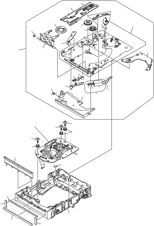
2.4 SLOT-IN MECHANISM SECTION
|
|
*3 |
|
|
7 |
|
17 |
5 |
|
|
11 |
|
3 |
15 |
|
14 |
|
|
|
|
|
|
*3 |
|
|
6 |
18 |
10 |
12 |
|
|
*2.9
8
4
13 *3 1 |
2 |
16 29
Refer to |
|
|
"2.5 TRAVERSE MECHANISM ASSY-S". |
26 |
|
19 |
||
26 |
||
|
||
|
25 |
|
26 |
|
25
27
28
*2. Dyefree : ME-913A (ZLX-ME413A) *3. Grease : ZLB-PN397B
22
21
20
23
21
10
CDJ-1000
∙ SLOT-IN MECHANISM SECTION PARTS LIST
Mark |
No. |
Description |
|
Part No. |
Mark |
No. |
Description |
|
Part No. |
NSP |
1 |
DC Motor |
|
DXM1093 |
|
16 |
Disc Guide |
|
DNK3914 |
|
2 |
Connector Assy |
|
PF02PY-B32 |
|
17 |
Clamper D4 Assy |
|
DXA1881 |
|
3 |
Clamp Spring |
|
DBH1374 |
NSP |
18 |
Slot-in Mechanism G5 Assy |
|
DXA1906 |
|
4 |
Guide Spring |
|
DBH1375 |
|
19 |
Traverse Mechanism Assy-S |
|
DXX2502 |
|
5 |
SW Lever Spacer (PET) |
|
DEC2420 |
|
20 |
Float Base (G5) Assy |
|
DXB1748 |
|
6 |
Loading Lever |
|
DNK3406 |
|
21 |
Vessel Cushion C |
|
DEC2424 |
|
7 |
Main Cam |
|
DNK3407 |
|
22 |
Vessel Cushion A |
|
DEC2257 |
|
8 |
Lever B |
|
DNK3558 |
|
23 |
Vessel Cushion B |
|
DEC2258 |
|
9 |
Lever A |
|
DNK3564 |
|
24 |
• • • • • |
|
|
|
10 |
Clamp Arm |
|
DNK3576 |
|
25 |
Float Rubber D3 |
|
DEB1404 |
|
11 |
Loading Base Assy-S |
|
DEA1022 |
|
26 |
Float Fastener |
|
DBA1139 |
|
12 |
Eject Lever |
|
DNK3684 |
|
27 |
Front Sheet |
|
DED1132 |
NSP |
13 |
Worm Gear |
|
DNK3910 |
|
28 |
Spacer POR (T3) |
|
DEB1467 |
|
14 |
Loading Gear |
|
DNK3911 |
|
29 |
Loading Motor Assy-S |
|
DEA1008 |
|
15 |
Drive Gear |
|
DNK3912 |
|
|
|
|
|
2.5 TRAVERSE MECHANISM ASSY-S
∙ TRAVERSE MECHANISM ASSY-S
|
|
12 |
|
|
PARTS LIST |
|
||
|
|
|
2 |
|
|
|||
|
|
|
|
Mark |
No. |
Description |
Part No. |
|
|
|
|
|
|
||||
|
|
*5 |
|
|
NSP |
1 |
Spindle Motor |
DXM1138 |
|
|
|
|
NSP |
2 |
Stepping Motor |
DXM1142 |
|
10 |
|
|
|
|
NSP |
3 |
Pickup Assy |
VWY1069 |
|
|
|
|
NSP |
4 |
Adjust Screw |
DBA1119 |
|
|
|
|
|
|
||||
|
|
|
|
|
NSP |
5 |
Precision Screw |
DBA1124 |
|
|
|
|
3 |
NSP |
6 |
Skew Spring |
DBH1437 |
|
|
|
|
NSP |
7 |
Joint Spring |
DBK1188 |
|
|
|
|
5 |
|
NSP |
8 |
Guide Shaft |
DLA1840 |
|
|
|
9 |
|
NSP |
9 |
Slider G4 |
DNK3733 |
|
|
|
|
NSP |
10 |
Mechanism Frame G5 |
DNK3776 |
|
|
|
|
|
|
||||
|
|
|
|
|
NSP |
11 |
Joint |
DNK3777 |
|
|
|
|
|
|
12 |
Screw |
BPZ20P080FMC |
|
*4 |
|
|
|
|
13 |
Screw |
BPZ26P080FMC |
4 |
6 |
|
7 |
|
|
|
|
|
|
|
|
|
|
|
|
||
|
|
6 |
|
|
|
|
|
|
|
|
|
|
|
|
|
|
|
|
|
|
*4 |
11 |
|
|
|
|
|
*5 |
|
|
|
|
|
|
|
|
*6 |
|
5 |
|
|
|
|
|
|
8 |
4 |
|
|
|
|
||
|
|
|
|
|
|
|||
|
|
8 |
|
|
|
|
|
|
|
|
1 |
|
|
|
|
|
|
|
|
*4. Screw Lock #300UB: ZBA-300UB |
|
|
|
|
||
|
|
*5. Grease: ZLB-PN397B |
|
|
|
|
|
|
13 |
|
*6. Grease: ZLB-PN948P |
|
|
|
|
|
|
11
|
1 |
|
2 |
|
3 |
|
4 |
|
|
|
|
|
|
CDJ-1000
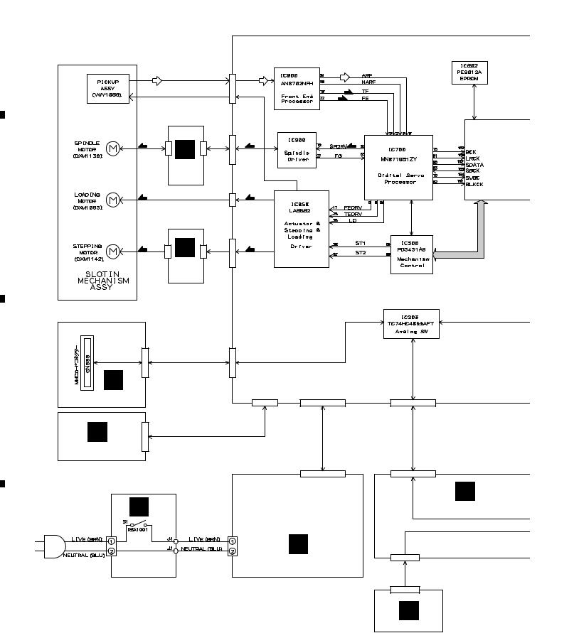
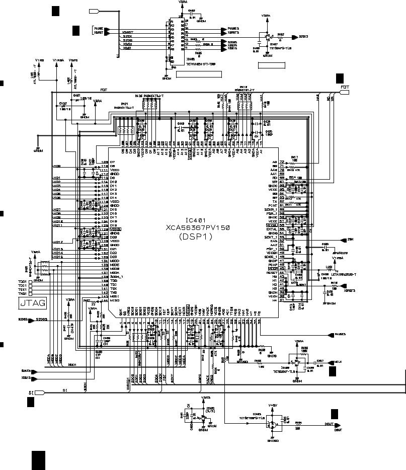
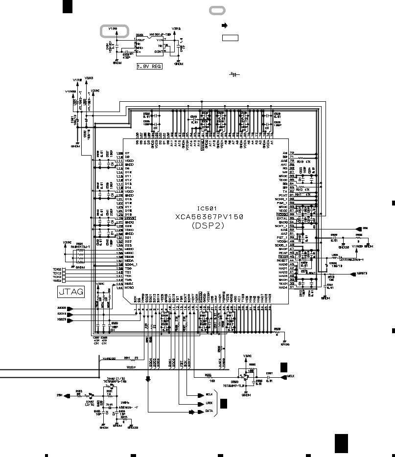
3. BLOCK DIAGRAM AND SCHEMATIC DIAGRAM
3.1 BLOCK DIAGRAM
A
|
(RF) |
|
|
CN800 |
(RF) |
|
|
|
|
(RF) |
(FS) |
|
|
|
|
|
|
|
|
|
|
|
(TS) |
|
CN911 |
|
CN912 |
CN900 |
|
|
B |
|
|
||
|
(SM) |
|
(SM) |
(SM) |
|
|
|
|
|||
|
|
SPCN |
|
|
|
|
|
ASSY |
|
|
|
|
|
|
|
CN302 |
|
B |
(LM) |
|
|
(LM) |
|
|
|
|
|
|
|
|
CN913 |
C |
CN914 |
CN950 |
|
|
|
|
|||
|
(CM) |
|
(CM) |
|
STCN
ASSY
CN99 CN202
F
C |
CN102 |
CN101 |
|
MMCB ASSY |
|||
|
|
||
CN1501 |
|
|
|
D |
|
|
|
FLRB ASSY |
|
|
|
|
|
CN2217 |
|
Q |
|
|
|
AN1 |
CN1 |
P |
|
|
|
||
PSWB ASSY |
SW POWER SUPPLY ASSY |
||
D |
|
|
|
CN203
CN1101
J
MFLB ASSY
J1701
J1701
K
RSWB ASSY
12
|
1 |
|
2 |
|
3 |
|
4 |
|
|
|
|
|
|
||||
|
|
|
|
|

|
5 |
|
6 |
|
7 |
|
8 |
|
|
|
|
CDJ-1000
SIGNAL ROUTE
|
(D) |
(FS) |
: FOCUS SERVO LOOP LINE |
|
|
: DIGITAL SIGNAL |
|
|
(PB) |
(TS) |
: TRACKING SERVO LOOP LINE |
|
|
: PB SIGNAL |
|
|
(RF) |
(SM) |
: SPINDLE MOTOR ROUTE |
|
: RF SIGNAL |
||
|
|
|
|
|
|
(CM) |
: CARRIAGE MOTOR ROUTE |
|
|
|
|
|
|
(LM) |
: LOADING MOTOR ROUTE |
|
|
|
|
|
CN12 |
CN1801 |
|
(D) |
(D) |
(D) |
JA1801 |
Digital Out |
|||
|
|
|
(D) |
|
CN13 |
CN1802 |
S1801 |
|
|
||
|
|
|
Digital Out |
|
|
|
ON/OFF |
|
|
J1801 |
I DOUT ASSY |
|
|
CN1904 |
|
|
JA1901 |
CN11 |
|
Control Jack |
|
|
|
(PB) |
|
(PB) |
|
BKB1017 |
|
|
(PB) |
|
CN1901 |
CN1902 |
CN1903 |
G DABBASSY |
H JACBASSY |
|
A MAIN ASSY
|
|
|
O |
|
|
|
JOGB ASSY |
|
CN1102 |
J1601 |
J1601 |
|
J1202 |
|
|
|
|
CN1201 |
|
J1101 |
J1103 |
|
|
|
|
N JFLB ASSY |
Sheet SW |
|
|
|
|
CN1401 |
CN1301 |
|
|
M |
L |
|
|
SLDB ASSY |
KSWB ASSY |
|
|
13
A
B
C
D
|
5 |
|
6 |
|
7 |
|
8 |
|
|
|
|
|
|
||||
|
|
|
|
|
A
B
C
D
1 |
|
2 |
|
3 |
|
4 |
|
|
|
|
|
CDJ-1000
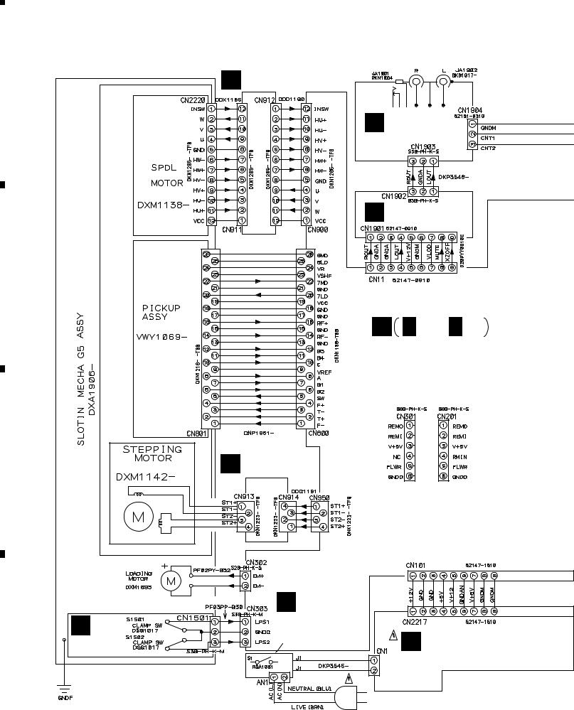
3.2 OVERALL WIRING DIAGRAM
AUDIO OUT
CONTROL
SPCN ASSY
B (DWX2170)
H JACB ASSY (DWX2163)
(WHT)
(WHT)
|
|
DABB ASSY |
|
|
|
G (DWX2162) |
|
MECHANISM ASSY-S |
|
A A 1/4 - A 4/4 |
|
TRAVERSE |
DXX2502 |
||
MAIN ASSY |
|||
|
|
(DWX2161) |
CONNECTOR FOR I/F
C STCN ASSY (DWX2171)
(FOR IC300) |
(FOR IC201) |
E
 SLMB ASSY (DWS1309)
EARTH LUG ASSY
DDF1015
AN1
KUC: AKP7032
TL, WY: BKP1046
Q
PSWB ASSY |
|
(KUC : DWS1312) |
SW POWER |
(TL, WY : DWS1311) |
|
|
P SUPPLY ASSY |
|
(DWR1344) |
AC POWER CORD
KUC : ADG7021
TL, WY : ADG1154
14
|
1 |
|
2 |
|
3 |
|
4 |
|
|
|
|
|
|
||||
|
|
|
|
|

|
5 |
|
6 |
|
7 |
|
8 |
|
|
|
|
|
|
CDJ-1000
Note : When ordering service parts, be sure to refer to "EXPLODED VIEWS and PARTS LIST" or "PCB PARTS LIST".
DIGITAL OUT |
DIGITAL OUT |
|
ON/OFF |
|
|
|
|
MMC CARD CONNECTOR |
|
|
A |
I |
DOUT ASSY |
MMCB ASSY |
(DWX2164) |
F (DWX2169) |
|
(GRN) |
|
KSWB ASSY |
|
|
L (DWS1307) |
M SLDB ASSY (DWS1308)
(GRN)
B
J J 1/2, J 2/2
MFLB ASSY (DWG1548)
C
|
RSWB ASSY |
|
K (DWS1310) |
|
JFLB ASSY |
|
N (DWG1549) |
FLRB ASSY |
|
D (DWX2166) |
JOGB ASSY |
|
O (DWG1550) |
SHEET SW |
D |
DSX1057 |
15
|
5 |
|
6 |
|
7 |
|
8 |
|
|
|
|
|
|
||||
|
|
|
|
|

1 |
2 |
3 |
4 |
CDJ-1000 |
|
|
|
3.3 MAIN (1/4), SPCN and STCN ASSYS |
|
|
|
A 1/4 |
MAIN ASSY |
|
A 2/4 |
|
(DWX2161) |
|
|
A |
|
|
|
To PICKUP ASSY CN801 |
|
|
|
|
|
|
6 |
|
|
|
(FS) |
|
|
|
4 |
|
|
|
(TS) |
B |
A 2/4 |
|
|
|
|
|
|
|
|
|
|
|
|
Q800 |
|
|
|
|
DTC124EUA |
|
A 2/4 |
|
Q600 |
|
|
|
|
2SA1577 |
A 2/4 |
|
|
|
|
|
|
|
A 2/4 |
|
|
|
A 2/4 |
|
(L) |
|
C |
(L) |
(TS) (FS) |
|
|
|
|
|||
|
|
|
||
|
|
|
|
|
|
|
|
(L) |
|
|
|
13 |
|
|
|
|
12 |
|
|
|
|
5 |
|
|
|
|
7 |
|
|
|
Q950 |
|
|
|
|
DTC124EUA |
|
|
|
|
|
(FS) |
|
A 2/4 |
|
|
|
|
|
|
|
|
(TS) |
|
|
A 2/4 |
|
(FS) |
|
|
|
|
|
|
D |
|
|
|
|
16 |
A 1/4 |
|
|
|
|
1 |
2 |
3 |
4 |
|
5 |
|
6 |
|
7 |
|
8 |
|
|
|
|
|
|
CDJ-1000
: RF SIGNAL ROUTE
(L)
: LOADING MOTOR SIGNAL ROUTE
(FS)
: FOCUS SERVO SIGNAL ROUTE
(TS)
: TRACKING SERVO SIGNAL ROUTE
A
A 3/4 |
|
|
|
|
B |
|
1110 18 19 |
|
|
|
|
|
|
|
Q701 |
|
|
|
|
DTC124EUA |
|
|
|
|
A 2/4 |
|
(FS) (TS) |
|
|
|
(L) |
(TS) (FS) |
|
|
|
|
|
|
|
A 2/4 |
|
|
|
|
C |
|
A 2/4 |
|
|
|
|
|
|
To |
|
|
|
|
SPINDLE |
|
|
STCN ASSY |
|
MOTOR |
|
|
|
(CN2220) |
||
|
C (DWX2171) |
|
|
|
|
To |
|
|
|
|
STEPPING |
|
|
|
|
MOTOR |
B |
SPCN ASSY |
|
|
|
(DWX2170) |
|
|
|
|
NOTES |
D |
|
|
|
ALL RESISTORS ARE IN Ω |
|
|
|
|
RS1/16S J |
|
|
|
|
ALL CAPACITORS ARE IN μF |
|
|
|
|
YF |
: CKSRYF |
|
|
|
CH |
: CCSRCH |
|
|
|
OTHERS : CKSRYB |
|
|
|
|
|
: CEHAR |
|
|
|
7 |
A 1/4 |
B C 17 |
5 |
6 |
|
8 |
|
|
1 |
2 |
|
3 |
|
4 |
|
CDJ-1000 |
|
|
|
|
|
|
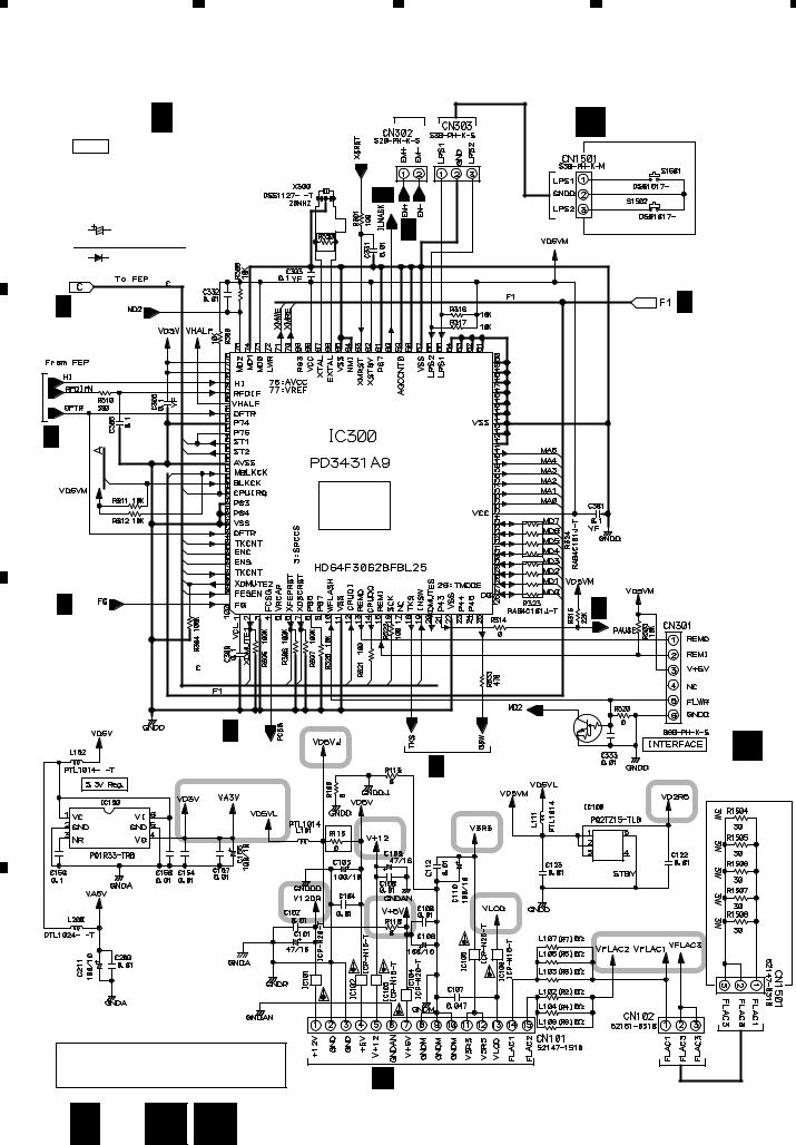
3.4 MAIN (2/4), FLRB and SLMB ASSYS |
|
|
|
||
|
A 2/4 |
|
To LOADING |
|
|
SLMB ASSY |
|
MAIN ASSY |
MOTOR |
|
E |
||
|
|
|
(DWS1309) |
|||
A |
NOTES |
(DWX2161) |
|
|
|
|
|
|
|
|
|
||
|
ALL RESISTORS ARE IN Ω |
|
1/4 |
|
|
RS1/16S J |
|
||
|
|
|
||
|
ALL CAPACITORS ARE IN μF |
|
A |
|
|
YF |
: CKSRYF |
|
|
|
|
|
||
|
CH |
: CCSRCH |
|
|
|
OTHERS |
: CKSRYB |
|
A 1/4 |
|
|
: CEHAR |
|
|
|
|
|
|
|
|
DIODE |
|
|
SLMB ASSY |
|
|
: 1SS355 |
|
S1501 : CLAMP SW |
|
|
|
|
S1502 : CLAMP SW |
|
A 1/4 |
|
|
A 3/4 |
B |
A 1/4 |
|
|
|
|
|
|
|
|
|
|
|
|
MECHA. |
|
|
|
|
CONTROL |
|
|
|
|
CPU |
|
A 1/4 |
|
|
A 4/4 |
C |
|
|
A 1/4 |
Q301 |
|
|
|
DTC124EUA |
|
|
|
|
|
D |
A 1/4 |
FLRB ASSY |
|
(DWX2166) |
D
CAUTION : FOR CONTINUED PROTECTION AGAINST RISK OF FIRE, REPLACE ONLY WITH SAME TYPE NO. ICP-N20, MFD BY ROHM CO., LTD. FOR IC101 AND IC104.
P CN2217
18 A 2/4 D 
 E
E
|
1 |
|
2 |
|
3 |
|
4 |
|
|
|
|
|
|
||||
|
|
|
|
|
|
5 |
|
6 |
|
7 |
|
8 |
|
|
|
|
|
|
CDJ-1000
|
|
: The power supply is shown with the marked box. |
|
|
|
|
|
A 3/4 |
A |
|
A 3/4,4/4 |
|
|
|
|
|
|
|
|
|
Q201 |
|
|
|
|
DTC124EUA |
|
A 3/4 |
|
|
|
|
|
|
|
|
1 |
|
|
|
|
|
|
B |
|
|
|
Q202 |
|
|
|
|
DTA124EUA |
|
|
|
SYSTEM |
|
|
|
|
CONTROL |
|
|
|
|
CPU |
A 3/4 |
|
|
|
|
|
|
|
|
3 |
2 |
|
A 3/4 |
|
|
|
|
|
|
|
|
C |
|
A 4/4 |
A 3/4 |
F |
|
|
|
|
||
|
|
|
|
|
|
|
|
CN99 |
|
|
|
|
Q203 |
|
|
|
|
Q204 |
|
|
|
|
2SC4081 |
|
|
|
|
Q203 |
|
|
|
|
DTC124EUA |
D |
J 1/2 |
CN1101 |
|
|
|
|
|
|
||
CAUTION : FOR CONTINUED PROTECTION AGAINST RISK OF FIRE, REPLACE ONLY WITH SAME TYPE NO. ICP-N15, MFD BY ROHM CO., LTD. FOR IC102 AND IC103.
CAUTION : FOR CONTINUED PROTECTION AGAINST RISK OF FIRE, REPLACE ONLY WITH SAME TYPE NO. ICP-N25, MFD BY ROHM CO., LTD. FOR IC105.
CAUTION : FOR CONTINUED PROTECTION AGAINST RISK OF FIRE, REPLACE ONLY WITH SAME TYPE NO. ICP-N10, MFD BY ROHM CO., LTD. FOR IC106.
A 2/4 19
|
5 |
|
6 |
|
7 |
|
8 |
|
|
|
|
|
|
||||
|
|
|
|
|
|
1 |
|
2 |
|
3 |
|
4 |
|
|
|
|
|
|
CDJ-1000
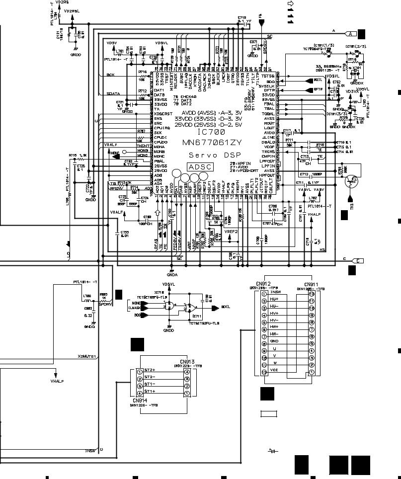
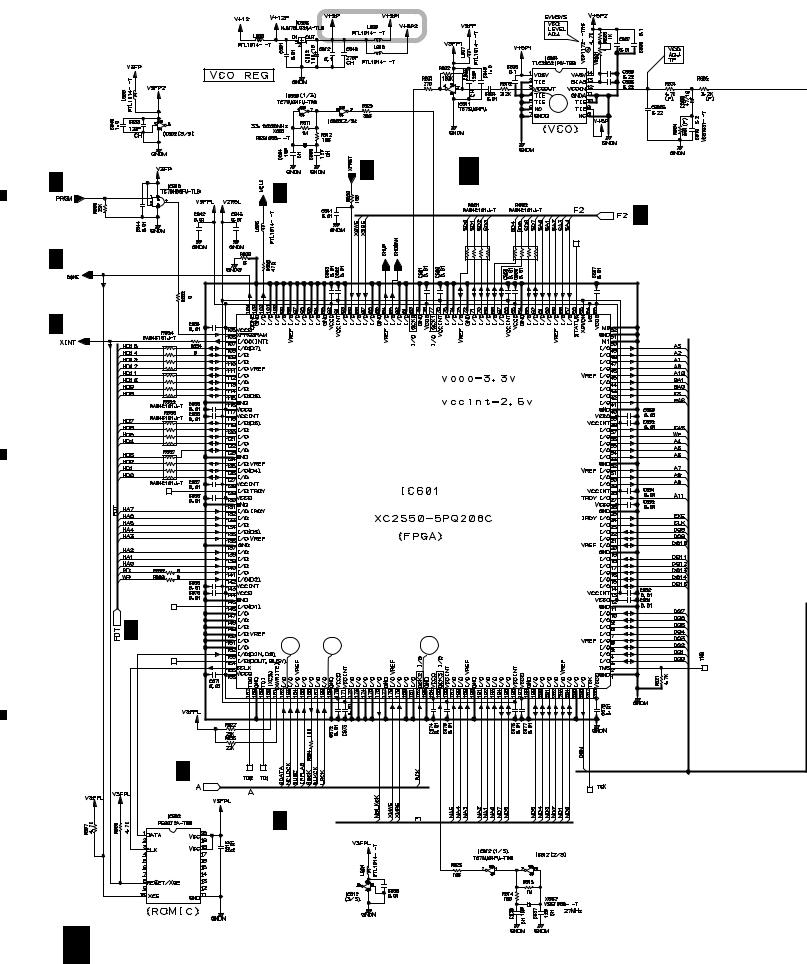
3.5 MAIN (3/4) and MMCB ASSYS
A
B
C
|
|
|
17 |
A 2/4 |
|
A 2/4 |
A 3/4 MAIN ASSY (DWX2161) |
A 3/4,4/4 |
|
||
|
|
||
|
|
|
A 2/4 |
A 2/4 |
|
|
|
A 2/4 |
|
|
|
|
A 4/4 |
|
15 |
|
14 |
16 |
|
|
A 1/4 |
|
|
A 2/4

D
20 A 3/4
|
1 |
|
2 |
|
3 |
|
4 |
|
|
|
|
|
|
||||
|
|
|
|
|
|
5 |
|
|
6 |
|
|
|
|
|||
|
|
|
|
|
|
|
|
|
|
|
|
|
|
|
|
|
|
|
|
|
|
|
|
Q11
DTA124EUA
(D)
A 4/4
(GUARD GND)
7 |
|
8 |
|
CDJ-1000
: The power supply is shown with the marked box.
NOTES
ALL RESISTORS ARE IN Ω
A |
2/4,4/4 |
RS1/16S J |
|
|
|
||
|
|
ALL CAPACITORS ARE IN μF |
|
|
|
||
|
|
YF |
: CKSRYF |
|
|
CH |
: CCSRCH |
|
|
OTHERS |
: CKSRYB |
:CEHAR
:PB AUDIO SIGNAL ROUTE
(D)
: DIGITAL DATA SIGNAL ROUTE
|
G CN1901 |
|
A 2/4 |
|
CN1802 |
|
I |
A 4/4 |
CN1801 |
|
|
|
I |
CONNECTOR |
A 2/4 |
|
|
||
MMC CARD |
CN202 |
|
F |
||
|
||
|
MMCB ASSY |
|
(BODY GND) |
(DWX2169) |
|
|
A 3/4 F 21 |
A
B
C
D
|
5 |
|
6 |
|
7 |
|
8 |
|
|
|
|
|
|
||||
|
|
|
|
|
|
1 |
|
2 |
|
3 |
|
4 |
|
|
|
|
|
|
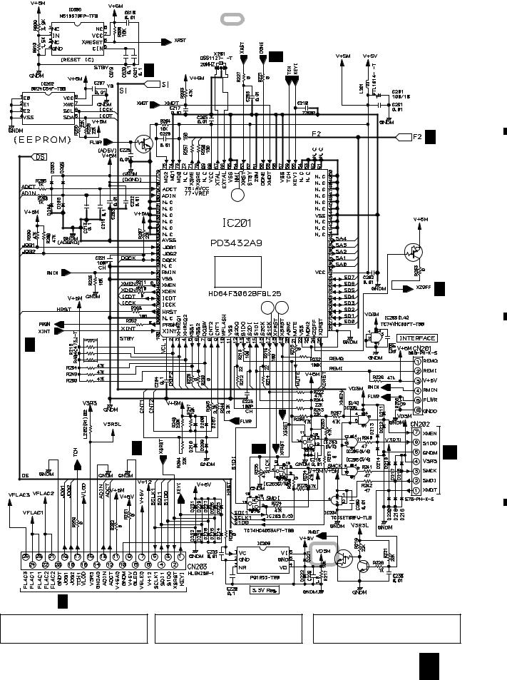
CDJ-1000
3.6 MAIN ASSY (4/4)
A 2/4,3/4 
A
A 2/4
|
|
INVERTER |
|
5V → 3.3V BUFFER |
A 3/4 |
|
|
|
B |
|
|
C |
|
|
|
|
A 3/4 |
D |
A 2/4,3/4 |
|
|
A 3/4 |
|
|
|
22 A 4/4
|
1 |
|
2 |
|
3 |
|
4 |
|
|
|
|
|
|
||||
|
|
|
|
|
|
5 |
|
6 |
|
|
A 4/4 MAIN ASSY (DWX2161)
|
7 |
|
8 |
|
|
|
|
CDJ-1000
: The power supply is shown with the marked box. |
A |
|
(D)
: DIGITAL DATA SIGNAL ROUTE
NOTES
ALL RESISTORS ARE IN Ω
RS1/16S J
ALL CAPACITORS ARE IN μF
YF |
: CKSRYF |
|
CH |
: CCSRCH |
|
OTHERS |
: CKSRYB |
|
|
: CEHAR |
|
|
|
|
|
|
|
|
|
|
|
B |
|
|
|
|
C |
|
(D) |
|
A 3/4 |
|
|
|
|
|
|
|
|
|
|
D |
|
|
A 3/4 |
|
|
|
|
(D) |
|
|
|
|
7 |
A 4/4 |
23 |
5 |
6 |
8 |
|
|
1 |
|
2 |
|
|
|
|
CDJ-1000
3.7 DABB, JACB and DOUT ASSYS
A
A 3/4
CN11
B
Q1906
DTA124EUA
C
A 3/4
CN12
G DABB ASSY (DWX2162)
Q1903
2SD2144S
Q1904
2SD2144S
Q1905
DTC124EUA
DIGITAL OUT
ON/OFF
A 3/4
CN13
D
24 G
 I
I
3 |
|
4 |
|
|
|
NJM4580D
Q1901
2SD2144S
Q1902
2SD2144S
NJM4580D
Q1907
2SA1145
I DOUT ASSY (DWX2164)
DIGITAL
OUT
|
1 |
|
2 |
|
3 |
|
4 |
|
|
|
|
|
|
||||
|
|
|
|
|
|
5 |
|
6 |
|
7 |
|
8 |
|
|
|
|
|
|
CDJ-1000
A
H JACB ASSY (DWX2163)
AUDIO
OUT
B
CONTROL
: The power supply is shown with the marked box.
NOTES
ALL RESISTORS ARE IN Ω
RS1/16S J
ALL CAPACITORS ARE IN μF
YF |
: CKSRYF |
CH |
: CCSRCH |
OTHERS |
: CKSRYB |
|
: CEHAR |
 : PB AUDIO SIGNAL ROUTE
C
D
H 25
|
5 |
|
6 |
|
7 |
|
8 |
|
|
|
|
|
|
||||
|
|
|
|
|
|
1 |
|
2 |
|
3 |
|
4 |
|
|
|
|
|
|
CDJ-1000
3.8 MFLB (1/2) and RSWB ASSYS
A |
J 1/2 MFLB ASSY (DWG1548) |
|
: The power supply is shown with the marked box.
|
|
|
J 2/2 |
|
|
|
|
|
DISPLAY |
|
|
|
|
MICROCOMPUTER |
B |
|
|
|
|
|
A 2/4 |
|
|
|
|
CN203 |
|
|
|
C |
|
|
|
|
D |
|
|
|
|
|
|
|
M CN1401 |
N J1202 |
26 |
J 1/2 |
|
|
|
|
1 |
2 |
3 |
4 |
|
5 |
|
|
6 |
7 |
|
|
8 |
|
|
|
|
|
|
|
|
CDJ-1000 |
|
|
SWITCHES |
|
: 0 (EJECT) |
|
|
|
|
|
|
|
MFLB ASSY |
S1106 |
S1113 |
: IN/REALTIME CUE |
|
|
|
A |
||
S1101 |
: A |
S1107 |
: SELECT |
S1114 |
: LOOP OUT |
|
|
|
|
|
|
|
|
||||||
S1102 |
: B |
|
VINYL – CDJ |
S1115 |
: RELOOP/EXIT |
|
|
|
|
S1103 |
: C |
S1109 |
: 2 CALL |
S1116 |
: 2 WAVE |
|
|
|
|
S1104 |
: DISPLAY |
S1110 |
: CALL 3 |
S1117 |
: WAVE 3 |
|
|
|
|
|
TEXT/WAVE |
S1111 |
: MEMORY |
S1118 |
: EJECT LOCK |
|
|
|
|
S1105 |
: TIME MODE |
S1112 |
: DELETE |
S1119 |
: SELECT |
|
|
|
|
|
|
|
|
RSWB ASSY |
|
|
|
|
|
|
|
|
|
S1701 |
: FWD – REV |
|
|
|
|
|
|
|
|
|
Q1103 |
|
|
|
|
|
|
|
|
|
DTC124EUA |
|
|
|
|
|
|
|
S1101-S1103,S1113-S1115 : DSG1063 |
|
|
|
|
||
|
|
|
S1104-S1107,S1109-S1112 : ASG7013 |
|
|
|
|
||
|
|
|
S1116,S1117,S1119 |
: ASG7013 |
|
|
|
|
|
|
|
|
|
|
Q1104 |
|
|
|
|
|
|
|
|
|
DTC124EUA |
|
|
|
|
|
|
|
|
|
|
|
|
|
B |
|
|
|
|
|
Q1106 |
|
|
|
|
|
|
|
|
|
DTC124EUA |
|
|
|
|
|
|
|
|
|
Q1107 |
|
|
|
|
|
|
|
|
|
DTC124EUA |
|
|
|
|
|
|
|
|
|
Q1108 |
|
|
|
|
|
|
|
|
|
DTC124EUA |
|
|
|
|
|
|
|
|
|
Q1109 |
|
|
|
|
|
|
|
|
|
DTC124EUA |
|
|
|
|
|
|
Q1101 |
|
|
|
|
|
|
|
|
|
DTC124EUA |
|
|
Q1110 |
|
|
|
|
|
|
|
|
|
|
|
|
|
|
|
|
|
|
|
DTC124EUA |
|
|
|
|
|
|
|
|
D1104-D1107: |
|
|
|
|
|
|
|
|
|
EMAY3864X-HM |
|
|
|
|
|
|
|
Q1102 |
|
|
Q1111 |
|
|
|
|
|
|
|
|
DTC124EUA |
|
|
|
|
|
|
|
DTC124EUA |
|
|
|
|
|
|
|
|
|
|
|
|
|
|
|
|
C |
|
|
|
|
|
Q1112 |
|
|
|
|
|
|
|
|
|
DTA124EUA |
|
|
|
|
|
|
|
|
10k-B |
10k-B |
|
|
|
|
|
|
|
J 2/2 |
|
|
|
|
|
|
|
|
|
NOTES |
|
|
K |
RSWB ASSY |
D |
|
|
|
|
ALL RESISTORS ARE IN Ω |
(DWS1310) |
|
||||
|
L CN1301 |
RS1/16S J |
|
|
|
|
|
||
|
ALL CAPACITORS ARE IN μF |
|
|
|
|
||||
|
YF |
: CKSRYF |
|
|
|
|
|
||
|
|
|
CH |
: CCSRCH |
|
|
|
|
|
|
|
|
OTHERS : CKSRYB |
|
|
|
|
|
|
|
|
|
|
: CEHAR |
|
J 1/2 |
K 27 |
|
|
|
|
|
|
|
7 |
|
|||
|
5 |
|
|
6 |
|
|
8 |
|
|
|
1 |
|
2 |
|
3 |
|
4 |
|
|
|
|
|
|
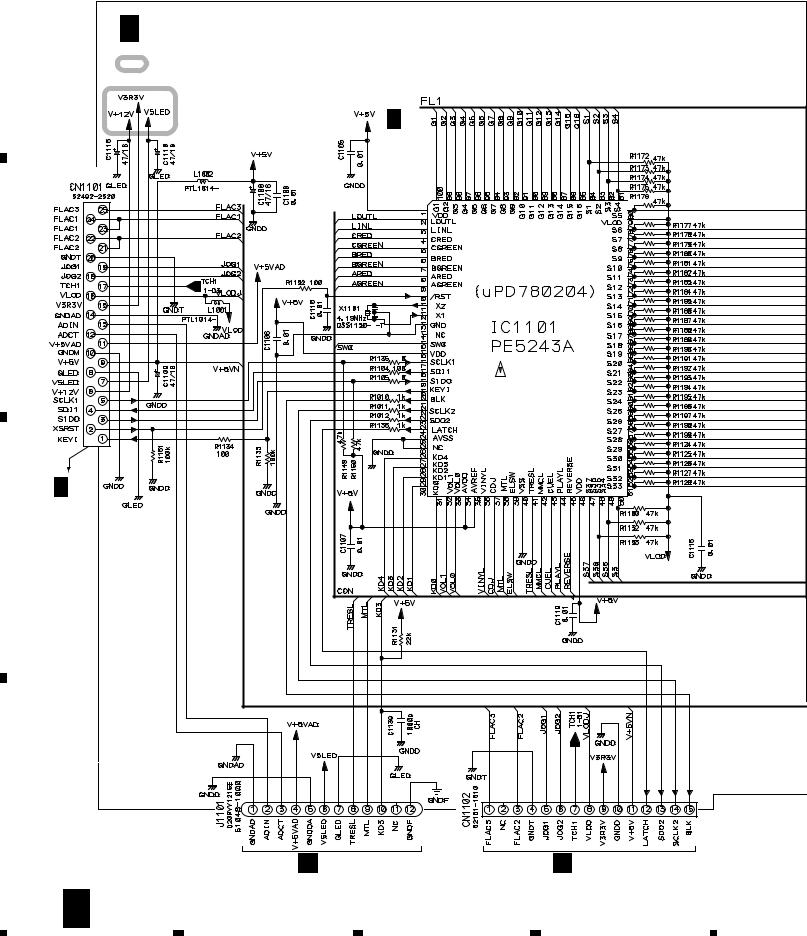
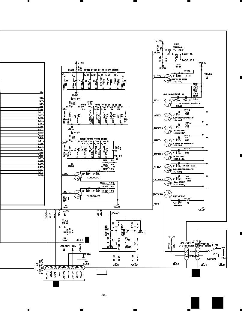
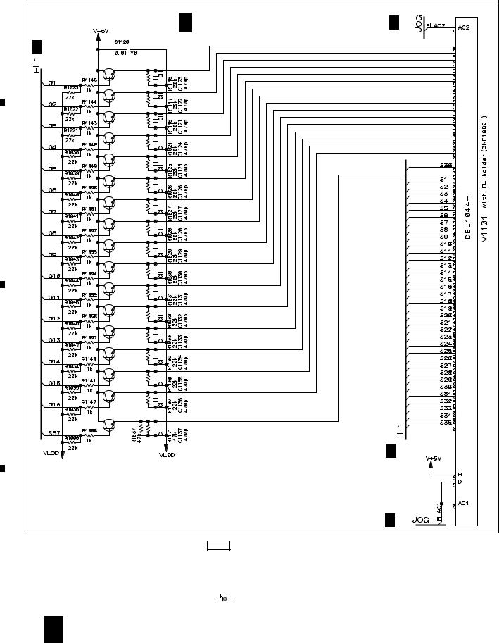
CDJ-1000
3.9 MFLB ASSY (2/2
A |
J 2/2 MFLB ASSY (DWG1548) |
J 1/2 |
|
||
|
J 1/2 |
|
|
Q1118 |
|
|
Q1117 |
|
|
Q1116 |
|
|
Q1008 |
|
|
Q1009 |
|
|
Q1010 |
|
B |
Q1011 |
|
|
Q1012 |
|
|
Q1013 |
|
|
Q1014 |
TUBE |
|
|
|
|
Q1015 |
FL INDICATOR |
|
Q1016 |
|
|
Q1017 |
|
|
Q1113 |
|
|
Q1114 |
|
C |
|
|
|
Q1115 |
|
|
Q1007 |
|
|
Q1007-Q1017,Q1113-Q1118: |
J 1/2 |
|
|
|
|
2SC4081 |
|
|
|
J 1/2 |
|
NOTES |
|
D |
ALL RESISTORS ARE IN Ω |
||
RS1/16S J |
|||
|
|||
|
ALL CAPACITORS ARE IN μF |
||
|
YF |
: CKSRYF |
|
|
CH |
: CCSRCH |
|
|
OTHERS |
: CKSRYB |
|
|
|
: CEHAR |
|
28 J 2/2
|
1 |
|
2 |
|
3 |
|
4 |
|
|
|
|
|
|
||||
|
|
|
|
|
 Loading...