

Page 1
English
Español
Deutsch
Français
Italiano
Nederlands
AVX-7600
This product conforms to new cord colors.
Los colores de los cables de este producto se conforman con un nuevo código de colores.
Dieses Produkt entspricht den neuen Kabelfarben.
Le code de couleur des câbles utilisé pour ce produit est
nouveau.
Questo prodotto è conforme ai nuovi codici colori.
De kleuren van de snoeren van dit toestel zijn gewijzigd.
INSTALLATION MANUAL
MANUEL D’INSTALLATION
Page 2

1
Contents
Connecting the Units ................................ 1
Connecting the power cord .............................. 3
When connecting with a Pioneer head unit ...... 5
When connecting with a car stereo
with RCA audio input ................................ 6
When connecting with a DVD player .............. 7
When connecting with a rear view camera ...... 8
Installation ................................................ 10
DIN Front/Rear-mount .................................... 11
DIN Front-mount ............................................ 11
DIN Rear-mount .............................................. 12
Fixing the front panel ...................................... 12
WARNING:
• To avoid the risk of accident and the
potential violation of applicable laws,
the front DVD or TV feature should
never be used while the vehicle is being
driven. Also, Rear Displays should not
be in a location where it is a visible distraction to the driver.
• In some countries or states the viewing
of images on a display inside a vehicle
even by persons other than the driver
may be illegal. Where such regulations
apply, they must be obeyed.
CAUTION:
• PIONEER does not recommend that
you install or service your display yourself. Installing or servicing the product
may expose you to risk of electric shock
or other hazards. Refer all installation
and servicing of your display to authorized Pioneer service personnel.
• Secure all wiring with cable clamps or
electrical tape. Do not allow any bare
wiring to remain exposed.
• Do not drill a hole into the engine compartment to connect the yellow lead of
the unit to the vehicle battery. Engine
vibration may eventually cause the insulation to fail at the point where the wire
passes from the passenger compartment
into the engine compartment. Take
extra care in securing the wire at this
point.
• It is extremely dangerous to allow the
display lead to become wound around
the steering column or gearshift. Be sure
to install the display in such a way that
it will not obstruct driving.
• Make sure that wires will not interfere
with moving parts of the vehicle, such as
the gearshift, parking brake or seat sliding mechanism.
• Do not shorten any leads. If you do, the
protection circuit may fail to work
properly.
Connecting the Units
Page 3
English
Español
Deutsch
Français
Italiano
Nederlands
2
Note:
• This unit is for vehicles with a 12-volt battery and
negative grounding. Before installing it in a recreational vehicle, truck, or bus, check the battery
voltage.
• To avoid shorts in the electrical system, be sure to
disconnect the ≠ battery cable before beginning
installation.
• Refer to the owner’s manual for details on
connecting the power amp and other units, then
make connections correctly.
• Secure the wiring with cable clamps or adhesive
tape. To protect the wiring, wrap adhesive tape
around them where they lie against metal parts.
• Route and secure all wiring so it cannot touch any
moving parts, such as the gear shift, handbrake
and seat rails. Do not route wiring in places that
get hot, such as near the heater outlet. If the insulation of the wiring melts or gets torn, there is a
danger of the wiring short-circuiting to the vehicle
body.
• Don’t pass the yellow lead through a hole into the
engine compartment to connect to the battery.
This will damage the lead insulation and cause a
very dangerous short.
• Do not shorten any leads. If you do, the protection
circuit may fail to work when it should.
• Never feed power to other equipment by cutting
the insulation of the power supply lead of the unit
and tapping into the lead. The current capacity of
the lead will be exceeded, causing overheating.
• When replacing fuse, be sure to use only fuse of
the rating prescribed on the fuse holder.
• If the RCA pin jack on the unit will not be used,
do not remove the caps attached to the end of the
connector.
• If this unit is installed in a vehicle that does not
have an ACC (accessory) position on the ignition
switch, the red lead of the unit should be connected to a terminal coupled with ignition switch
ON/OFF operations. If this is not done, the vehicle battery may be drained when you are away
from the vehicle for several hours. (Fig. 1)
Fig. 1
No ACC positionACC position
• Cords for this product and those for other products may be different colors even if they have
the same function. When connecting this product
to another product, refer to the supplied manuals
of both products and connect cords that have the
same function.
C
C
A
O
F
N
F
O
S
T
A
R
T
O
F
N
F
O
S
T
A
R
T
Page 4
3
Connecting the Units
Connecting the power cord
Yellow
To terminal always supplied
with power regardless of
ignition switch position.
Fuse holder
Fuse resistor
Red
To electric terminal controlled
by ignition switch (12 V DC)
ON/OFF.
Black (ground)
To vehicle (metal) body.
Orange/white
To lighting switch terminal.
Fuse resistor
This product
Violet/white
See the section “When connecting
with a rear view camera”
Audio output
(AUDIO OUTPUT)
15 cm
Page 5
English
Español
Deutsch
Français
Italiano
Nederlands
Fig. 2
4
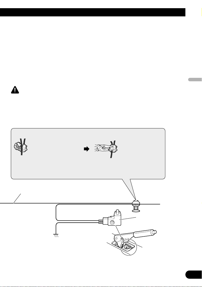
Note:
• The position of the parking brake switch depends
on the vehicle model. For details, consult the
vehicle Owner’s Manual or dealer.
Connection method
Clamp the lead.1. 2. Clamp firmly with
needle-nosed
pliers.
WARNING
Parking brake
switch
Power supply side
Ground side
Light green
Used to detect the ON/OFF status of the parking brake.
This lead must be connected to the power supply side of the parking
brake switch.
LIGHT GREEN LEAD AT POWER CONNECTOR IS DESIGNED TO
DETECT PARKED STATUS AND MUST BE CONNECTED TO THE
POWER SUPPLY SIDE OF THE PARKING BRAKE SWITCH. IMPROPER
CONNECTION OR USE OF THIS LEAD MAY VIOLATE APPLICABLE
LAW AND MAY RESULT IN SERIOUS INJURY OR DAMAGE.
Page 6
5
Connecting the Units
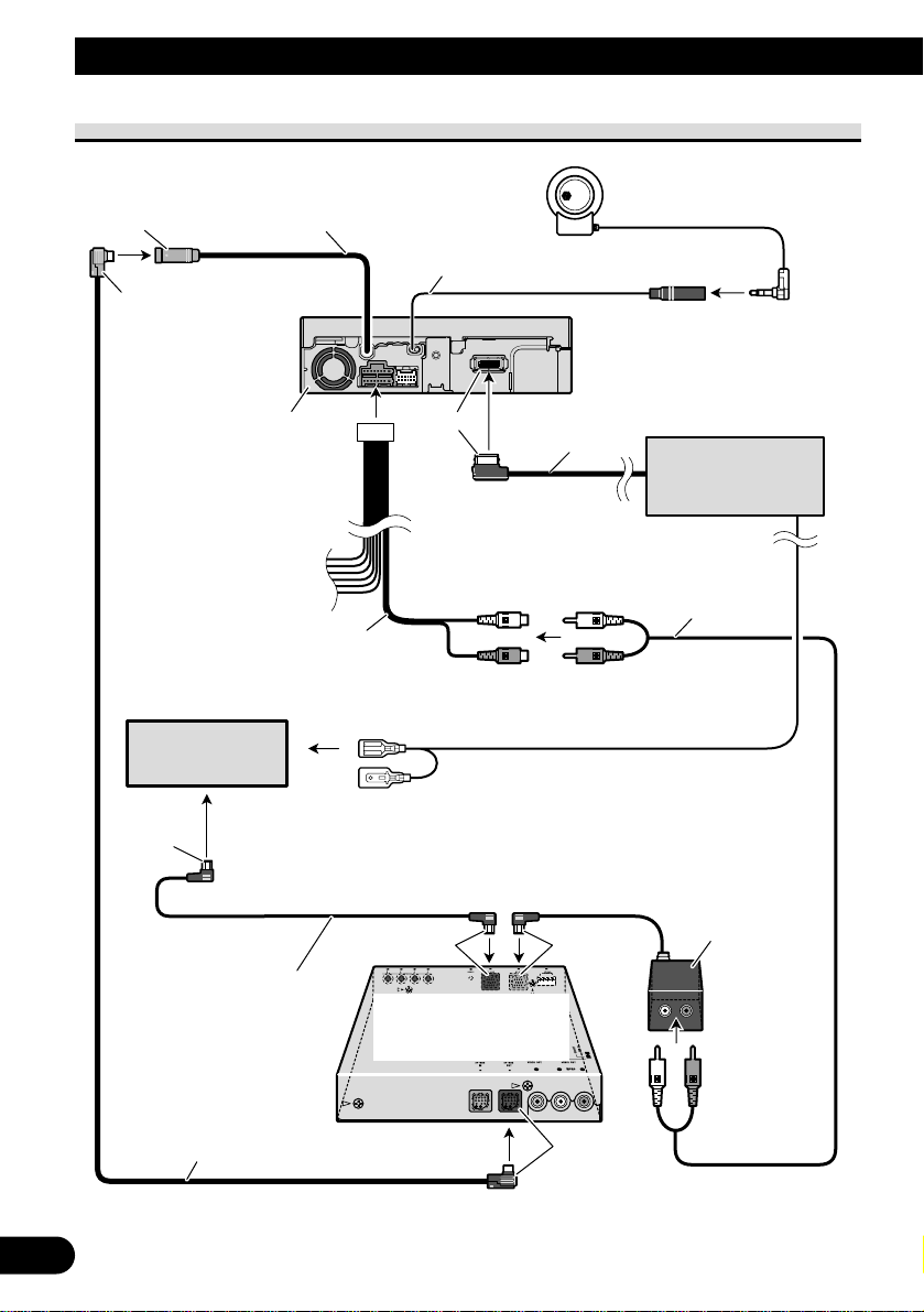
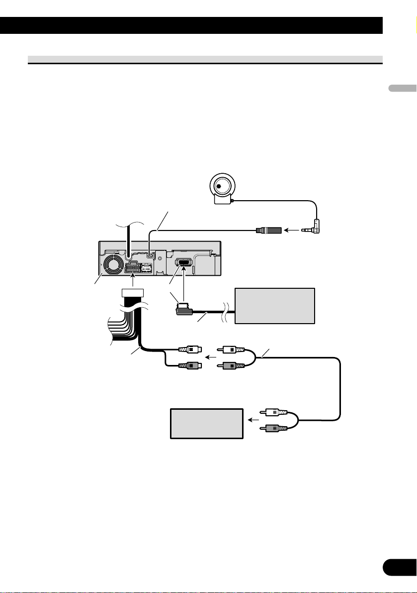
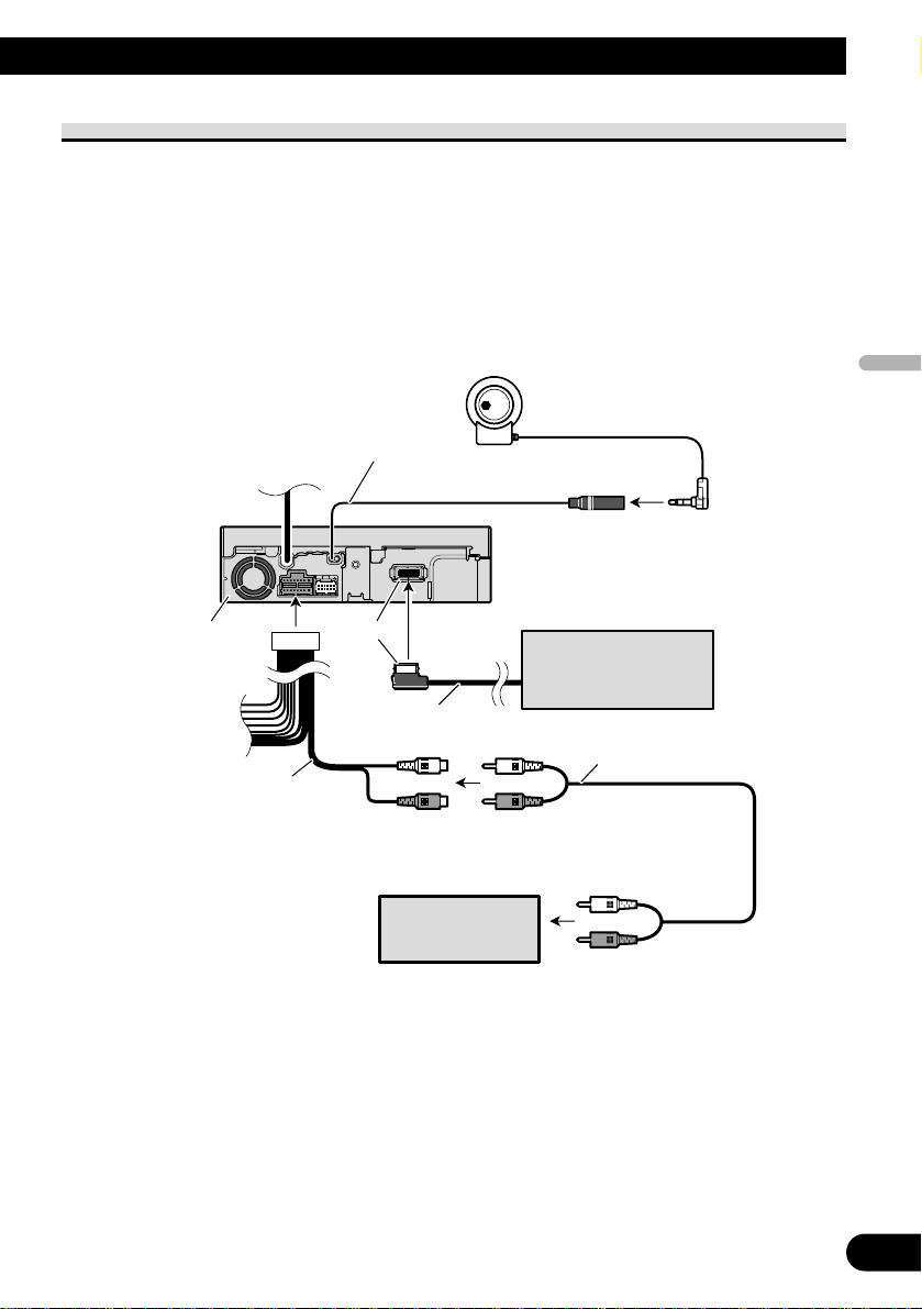
When connecting with a Pioneer head unit
Fig. 3
RCA to IP-BUS
inter connector
(e.g. CD-RB10)
(sold separately)
Hide-away TV tuner
(e.g. GEX-P6400TVP)
(sold separately)
AV-BUS input (Blue)
Navigation unit
(e.g. AVIC-900DVD)
(sold separately)
26 pin cable
Yellow
AV-BUS cable (supplied
with TV tuner)
IP-BUS cable (supplied
with TV tuner)
40 cm
Black Blue
Black
Blue
Blue
This product
Head unit
(sold separately)
Guide speaker output
(GUIDE SP OUTPUT)
Guide speaker
(e.g. CD-TS37GP)
(sold separately)
15 cm
If you use this unit with a navigation
unit (e.g. AVIC-900DVD), be sure to
connect a guide speaker to this unit’s
guide speaker output terminal.
To IP-BUS input (Blue)
Yellow/black
Audio output
(AUDIO OUTPUT)
15 cm
RCA cable
(sold separately)
Page 7
English
Español
Deutsch
Français
Italiano
Nederlands
6
When connecting with a car stereo with RCA audio input
Fig. 4
Navigation unit
(e.g. AVIC-900DVD)
(sold separately)
26 pin cable
Yellow
This product
Car stereo with
RCA input
Guide speaker output
(GUIDE SP OUTPUT)
Guide speaker
(e.g. CD-TS37GP)
(sold separately)
15 cm
If you use this unit with a navigation
unit (e.g. AVIC-900DVD), be sure to
connect a guide speaker to this unit’s
guide speaker output terminal.
Audio output
(AUDIO OUTPUT)
15 cm
RCA cable
(sold separately)
When connecting with a car
stereo with FM reception
capability, use a FM modulator
(e.g. CD-V61FM).
Page 8
7
Connecting the Units
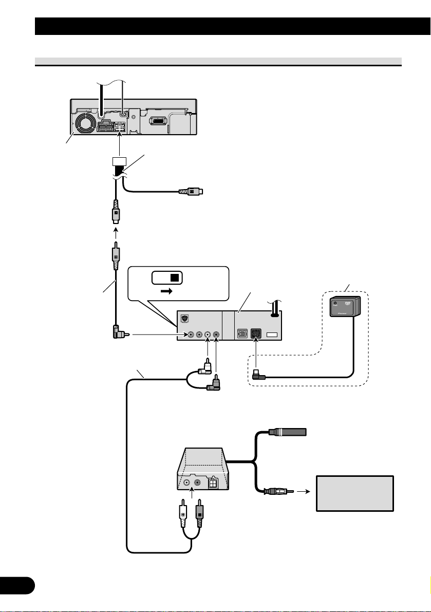
When connecting with a DVD player
Fig. 5
STAND ALONE
IP-BUS
This product
Car stereo with
FM reception
capability
RCA cable
(sold separately)
Video input 2
(VIDEO 2/BACK CAMERA INPUT)
Video input 1
(VIDEO 1 INPUT)
20 cm
DVD player
(e.g. SDV-P7)
(sold separately)
Remote sensor (supplied
with the DVD player)
RCA cable
(supplied with
the DVD
player)
FM modulator
(e.g. CD-V61FM)
(sold separately)
Page 9

English
Español
Deutsch
Français
Italiano
Nederlands
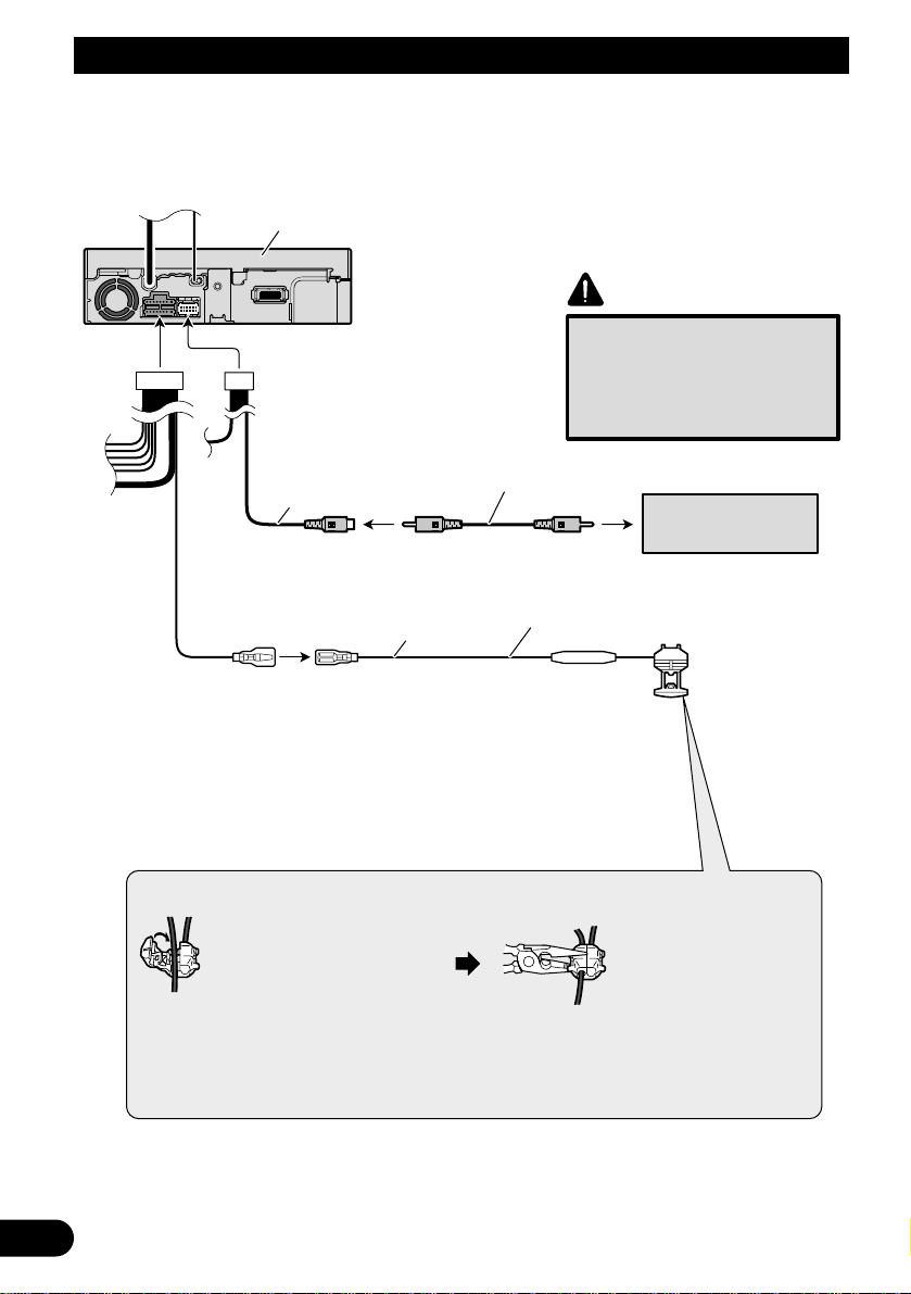
When connecting with a rear view camera
When using this product with a rear view camera, automatic switching to video from a
rear view camera when the gear shift is moved to REVERSE (R) position is possible.
WARNING:
• USE INPUT ONLY FOR REVERSE OR MIRROR IMAGE REAR VIEW CAMERA.
OTHER USE MAY RESULT IN INJURY OR DAMAGE.
CAUTION:
• The screen image may appear reversed.
• The rear view camera function is to use this product as an aid to keep an eye on trailers,
or backing into a tight parking spot. Do not use this function for entertainment purposes.
• The object in rear view may appear closer or more distant than in reality.
8
Page 10

9
Connecting the Units
Fig. 6
Connection method
Clamp the lead.1. 2. Clamp firmly with
needle-nosed
pliers.
CAUTION
Pioneer recommends the use of
a camera which outputs mirror
reversed images, otherwise
screen image may appear
reversed.
Fuse resistor
8m
Extension lead (supplied)
Rear view camera
Violet/white
Of the two lead wires connected to the back
lamp, connect the one in which the voltage
changes when the gear shift is in the REVERSE
(R) position. This connection enables the unit to
sense whether the car is moving forwards or
backwards.
RCA cable
(sold separately)
Note:
• It is necessary to set to AV INPUT2 in SETUP when
connecting a rear view camera.
To video output
This product
Video input 2
(VIDEO 2/BACK CAMERA INPUT)
20 cm
Page 11
English
Español
Deutsch
Français
Italiano
Nederlands
Installation
10
Note:
• Before finally installing the unit, connect the
wiring temporarily, making sure it is all connected up properly, and the unit and the system work
properly.
• Use only the parts included with the unit to ensure
proper installation. The use of unauthorized parts
can cause malfunctions.
• Consult with your nearest dealer if installation
requires the drilling of holes or other modifications of the vehicle.
• Install the unit where it does not get in the driver’s way and cannot injure the passenger if there
is a sudden stop, like an emergency stop.
• Do not install the display where it may (i) obstruct
the driver’s vision, (ii) impair the performance of
any of the vehicle’s operating systems or safety
features, including air bags, hazard lamp buttons
or (iii) impair the driver’s ability to safely operate
the vehicle.
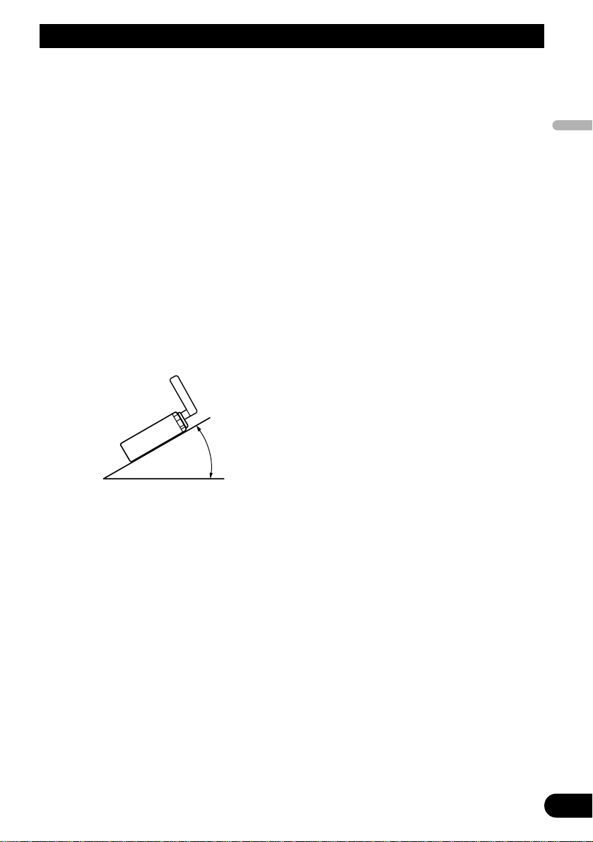
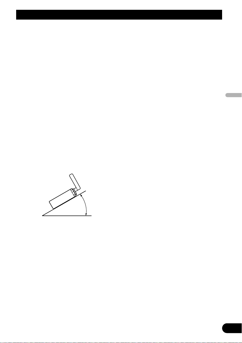
• If installation angle exceeds 30° from horizontal,
the unit might not give its optimum performance.
(Fig. 7)
Fig. 7
30°
Page 12
11
Installation
DIN Front/Rear-mount
This unit can be properly installed
either from “Front” (conventional DIN
Front-mount) or “Rear” (DIN Rearmount installation, utilizing threaded
screw holes at the sides of unit chassis). For details, refer to the following
illustrated installation methods.
Before installing the unit
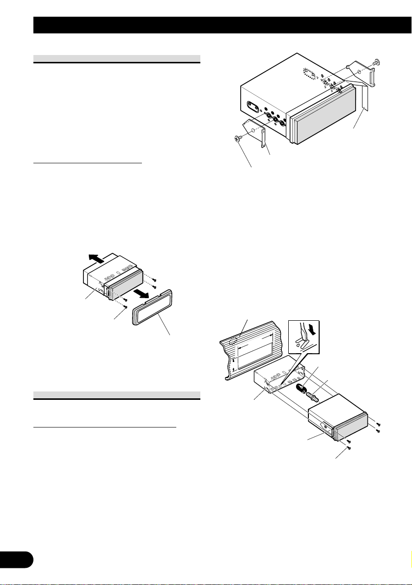
• Remove the frame and the holder. (Fig. 8)
Pull out to remove the frame and then
loosen the screws (2 × 3 mm) to
remove the holder. (When reattaching
the frame, point the side with a groove
downwards and attach it.)
Fig. 8
DIN Front-mount
Installation with the rubber bush
1. Decide the position of the side
brackets. (Fig. 9)
When installing in a shallow space,
change the position of side brackets. In
this case, stick conceal tape on parts
that protrude from the dashboard.
Fig. 9
2. Install the unit into the dashboard. (Fig. 10)
After inserting the holder into the
dashboard, then select the appropriate
tabs according to the thickness of the
dashboard material and bend them.
(Install as firmly as possible using the
top and bottom tabs. To secure, bend
the tabs 90 degrees.)
• After installing the unit into the
dashboard, reattach the frame.
Fig. 10
Rubber bush
Screw
Dashboard
Side bracket
Screw (2 × 3 mm)
182
53
Holder
Conceal tape
Side bracket
Flush surface screw (5 × 6 mm)
Holder
Frame
Screw (2 × 3 mm)
Page 13
English
Español
Deutsch
Français
Italiano
Nederlands
12
DIN Rear-mount
Installation using the screw holes on
the side of the unit
• Fastening the unit to the factory
radio mounting bracket. (Fig.
11) (Fig. 12) (Fig. 13)
Select a position where the screw holes
of the bracket and the screw holes of
this product become aligned (are fitted), and tighten the screws at 2 places
on each side. Use any of binding
screws (4 × 3 mm), binding screws (5
× 6 mm) or flush surface screws (5 × 6
mm), depending on the shape of the
screw holes in the bracket.
*1 Use binding screws (4 × 3 mm) only.
Fig. 11
• When installing in a shallow space,
use the following screw holes. In
this case, stick conceal tape on parts
that protrude from the dashboard.
Fig. 12
Fig. 13
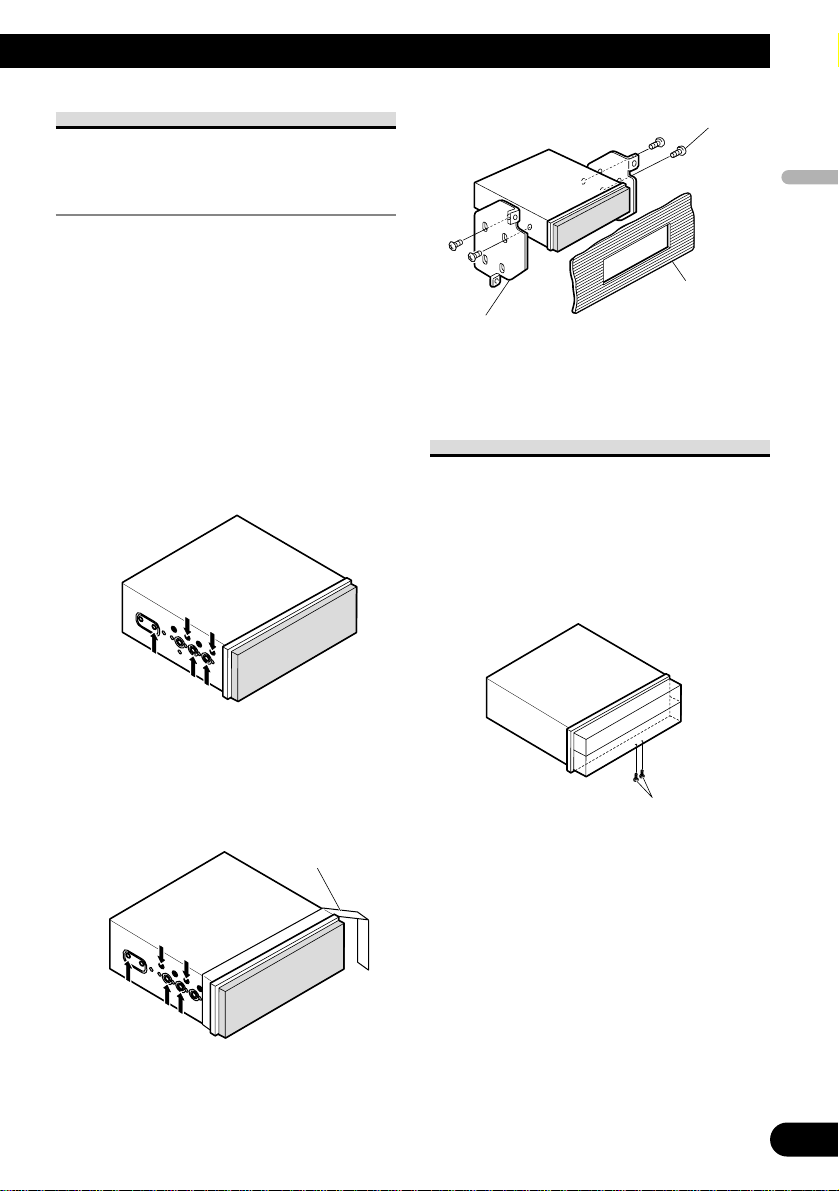
Fixing the front panel
If you do not operate the removing and
attaching the front panel function, use
the supplied fixing screws to fix the
front panel to this unit.
• Fix the front panel to the unit
using fixing screws. (Fig. 14)
Fig. 14
Fixing screws
Screw
Dashboard or
Console
Factory radio mounting
bracket
*
1
*
1
Conceal tape
*
1
*
1
Page 14

1
Contenido
Conexión de las unidades ........................ 1
Conexión del cable de alimentación .................. 3
Cuando conecte con una unidad
principal Pioneer ........................................ 5
Cuando conecte con un autoestéreo
con entrada de audio RCA ........................ 6
Cuando conecte con un reproductor
de DVD ...................................................... 7
Cuando conecte con una cámara
de vista trasera ............................................ 8
Instalación ................................................ 10
Montaje trasero/delantero DIN ........................ 11
Montaje delantero DIN .................................... 11
Montaje trasero DIN ........................................ 12
Fijación del panel delantero ............................ 12
ADVERTENCIA:
• Para evitar el riesgo de accidentes e
violación potencial de las leyes
aplicables, no se debe usar nunca la
función de DVD o TV frontal mientras
el vehículo esté siendo conducido.
Igualmente, los monitores traseros no
deben quedarse en un sitio donde
puedan causar una distracción visible al
conductor.
• En algunos países o estados, puede ser
ilícita la visualización de imágenes en un
display dentro de un vehículo, incluso
por otras personas que no sean el
conductor. En los casos en que resulten
aplicables, estas normas deben
respetarse.
PRECAUCIÓN:
• PIONEER no recomienda que sea usted
mismo quien instale o revise su pantalla.
La instalación o revisión del producto
puede exponerle a descargas eléctricas u
otros peligros. Solicite que todos los
trabajos de instalación y revisión de su
pantalla los realice el personal de
servicio Pioneer autorizado.
• Asegure todo el cableado con
abrazaderas de cables o cinta para usos
eléctricos. No permita que el cableado
pelado permanezca expuesto.
• No taladre un agujero en el
compartimiento del motor para
conectar el cable amarillo de la unidad a
la batería del vehículo. La vibración del
motor podría estropear el aislamiento
en el punto por donde el cable pasa del
compartimiento de los pasajeros al
compartimiento del motor. Tenga
mucho cuidado para mantener el buen
estado del cable en lo relativo a este
punto.
• Es peligrosísimo dejar que el cable de la
pantalla se enrolle en la base del volante
o en la palanca de cambios. Asegúrese
de instalar la pantalla de forma que ésta
no sea un obstáculo para la conducción.
• Asegúrese de que los cables no
interfieran con partes móviles del
vehículo tales como la palanca de
cambio, el freno de mano o el
mecanismo de deslizamiento de los
asientos.
• No acorte ningún cable. Si lo hace, el
circuito de protección tal vez no
funcione correctamente.
Conexión de las unidades
Page 15
English
Español
Deutsch
Français
Italiano
Nederlands
2
Nota:
• Esta unidad es para vehículos con batería de 12
voltios y con conexión a tierra. Antes de instalar
la unidad en un vehículo recreativo, camioneta, o
autobús, revise el voltaje de la batería.
• Para evitar cortocircuitos en el sistema eléctrico,
asegúrese de desconectar el cable de la batería ≠
antes de comenzar con la instalación.
• Consulte con el manual del usuario para los
detalles sobre la conexión de la alimentación de
amperios y de otras unidades, luego haga las
conexiones correctamente.
• Asegure el cableado con abrazaderas de cables o
con cinta adhesiva. Para proteger el cableado,
envuélvalo con cinta adhesiva donde éstos se
apoyan sobre las piezas de metal.
• Coloque y asegure todo el cableado de tal manera
que no toque las piezas en movimiento, tal como
la palanca de cambio de velocidades, el freno de
mano, y los pasamanos de los asientos. No
coloque el cableado en lugares que se calientan,
tal como cerca de la salida de un calefactor. Si el
material aislante del cableado se derritiera o se
gastara, habrá el peligro de un cortocircuito del
cableado a la carrocería del vehículo.
• No pase el conductor amarillo a través de un
orificio en el compartimiento del motor para
conectar a la batería. Esto dañará el material
aislante del conductor y causará un cortocircuito
peligroso.
• No acorte ningún conductor. Si lo hiciera, la
protección del circuito podría fallar al funcionar
cuando debería.
• Nunca alimente energía a otros equipos cortando
el aislamiento del conductor de alimentación
provista de la unidad y haciendo un empalme con
el conductor. La capacidad de corriente del
conductor se excederá, causando el
recalentamiento.
• Cuando reemplace algún fusible, asegúrese de
utilizar solamente un fusible del ratio descrito en
el soporte de fusibles.
• Si la toma de clavija RCA en la unidad no se usa,
retire las tapas fijadas al extremo del conector.
• Si se instala esta unidad en un vehículo que no
tiene una posición ACC (accesorio) en el
interruptor de encendido, el conductor rojo de la
unidad deberá conectarse al terminal conectado
con las operaciones del interruptor de encendido
ON/OFF. Si no se hace esto, la batería del
vehículo podría drenarse cuando usted esté lejos
del vehículo por varias horas. (Fig. 1)
Fig. 1
No en la posición ACCPosición ACC
• Los cables para este producto y aquéllas para
otros productos pueden ser de colores diferentes
aun si tienen la misma función. Cuando se
conecta este producto a otro, refiérase a los
manuales de ambos productos y conecte los
cables que tienen la misma función.
C
C
A
O
F
N
F
O
S
T
A
R
T
O
F
N
F
O
S
T
A
R
T
Page 16

3
Conexión de las unidades
Conexión del cable de alimentación
Violeta/blanco
Vea la sección “Cuando conecte
con una cámara de vista trasera”
Salida de audio
(AUDIO OUTPUT)
15 cm
Amarillo
Al terminal con suministro
constante de electricidad,
independientemente de la posición
del interruptor de encendido.
Rojo
Al terminal de energía eléctrica controlado por
el interruptor de encendido del vehículo (12 V
de CC.) ON/OFF.
Negro (masa)
A la carrocería del veículo
(parte metálica).
Anaranjado/blanco
Al terminal de interruptor de iluminación.
Este producto
Portafusible
Resistencia
de fusible
Resistencia
de fusible
Page 17
English
Español
Deutsch
Français
Italiano
Nederlands
Fig. 2
4
ADVERTENCIA
EL CABLE VERDE CLARO DEL CONECTOR DE ALIMENTACIÓN ESTÁ
DISEÑADO PARA DETECTAR SI EL VEHÍCULO ESTÁ ESTACIONADO
Y DEBE CONECTARSE CON EL LADO DE LA FUENTE DE
ALIMENTACIÓN DEL INTERRUPTOR DEL FRENO DE MANO. LA
CONEXIÓN O EL USO INCORRECTO DE ESTE CABLE PUEDE
INFRINGIR LAS LEYES PERTINENTES Y OCASIONAR LESIONES
FÍSICAS O DAÑOS GRAVES.
Interruptor del
freno de mano
Lado de alimentación
Lado de masa
Verde claro
Se utiliza para detectar el estado ON/OFF del freno de mano.
Este cable debe conectarse al lado de alimentación del
interruptor del freno de mano.
Nota:
• La posición del freno de estacionamiento depende
del modelo del vehículo. Para conocer detalles, consulte
el manual del propietario del vehículo o a su concesionario.
Método de conexión
Apriete el cable.1. 2. Apriete firmemente
con alicates de
punta de aguja.
Page 18

Cuando conecte con una unidad principal Pioneer
Fig. 3
5
Conexión de las unidades
RCA a interconector
IP-BUS (por ejemplo,
CD-RB10) (vendido
separadamente)
Sintonizador TV ocultolejos (GEX-P6400 TVP,
por exemplo) (vendido
separadamente)
Entrada AV-BUS (Azul)
Unidad de navegación
(AVIC-900DVD, por
exemplo)
(vendido separadamente)
Cable de 26 clavijas
Amarillo
Cable AV-BUS (suministrado
con el sintonizador de TV)
Cable IP-BUS (suministrado
con el sintonizador de TV)
40 cm
Negro Azul
Negro
Azul
Azul
Este producto
Unidad principal
(vendida
separadamente)
Salida de altavoz de guía
(GUIDE SP OUTPUT)
Altavoz de guía
(ej. CD-TS37GP)
(vendido separadamente)
15 cm
Si utiliza esta unidad con una unidad
de navegación (por ejemplo, AVIC900DVD), asegúrese de conectar un
altavoz de guía a este terminal de
salida de altavoz de guía de la unidad.
A la entrada IP-BUS (Azul)
Amarillo/negro
Salida de audio
(AUDIO OUTPUT)
15 cm
Cable RCA
(vendido
separadamente)
Page 19
English
Español
Deutsch
Français
Italiano
Nederlands
6
Cuando conecte con un autoestéreo con entrada de audio RCA
Fig. 4
Unidad de navegación
(AVIC-900DVD, por
exemplo)
(vendido separadamente)
Cable de 26 clavijas
Amarillo
Este producto
Autoestéreo con
entrada RCA
Salida de altavoz de guía
(GUIDE SP OUTPUT)
Altavoz de guía
(ej. CD-TS37GP)
(vendido separadamente)
15 cm
Si utiliza esta unidad con una unidad de
navegación (por ejemplo, AVIC900DVD), asegúrese de conectar un
altavoz de guía a este terminal de salida
de altavoz de guía de la unidad.
Salida de audio
(AUDIO OUTPUT)
15 cm
Cable RCA
(vendido separadamente)
Cuando conecte con un
autoestéreo con capacidad de
recepción FM, utilice un
modulador FM (por ejemplo,
CD-V61FM).
Page 20

Fig. 5
7
Conexión de las unidades
Cuando conecte con un reproductor de DVD
STAND ALONE
IP-BUS
Este producto
Autoestéreo con
capacidad de
recepción FM
Cable RCA
(vendido separadamente)
Entrada de vídeo 2
(VIDEO 2/BACK CAMERA INPUT)
Entrada de vídeo 1
(VIDEO 1 INPUT)
20 cm
Reproductor de
DVD (por ejemplo,
SDV-P7) (vendido
separadamente)
Sensor remoto
(suministrado con
reproductor de DVD)
Cable RCA
(suministrado con
el reproductor de
DVD)
Modulador FM (por
ejemplo, CD-V61FM)
(vendido separadamente)
Page 21
Cuando conecte con una cámara de vista trasera
Cuando utilice este producto con una cámara de vista trasera, se puede realizar la conmutación automática a vídeo desde una cámara de vista trasera cuando se desplaza la
palanca de cambio de marchas a REVERSE (R).
ADVERTENCIA:
• UTILICE SOLAMENTE PARA CÁMARA DE VISTA TRASERA DE IMAGEN
INVERTIDA O DE ESPEJO. CUALQUIER OTRO USO PUEDE CAUSAR LESIONES
O DAÑOS.
PRECAUCIÓN:
• La imagen de la pantalla puede aparecer invertida.
• La función de cámara de vista trasera es para utilizar de este producto como una ayuda
para mantener un ojo en remolques, o al estacionar de marcha atrás en un
estacionamiento estrecho. No utilice esta función para propósitos de entretenimiento.
• El objeto en la vista trasera puede parecer más próximo o más distante que en la
realidad.
English
Español
Deutsch
Français
Italiano
Nederlands
8
Page 22
9
Conexión de las unidades
Fig. 6
Método de conexión
Apriete el cable.
1. 2.
Apriete firmemente
con alicates de
punta de aguja.
PRECAUCIÓN
Resistencia
de fusible
8 m
Cable de extensión (suministrado)
Cámara de
vista trasera
Violeta/blanco
De los dos conductores conectados a la lámpara
trasera, conecte el conductor cuyo voltaje cambia
cuando se desplaza la palanca de cambio de marcha
a la posición REVERSE (R). Esta conexión permite
que la unidad detecte si el vehículo está se
moviendo hacia delante o hacia atrás.
Cable RCA
(vendido separadamente)
Nota:
• Se requiere ajustar a AV INPUT2 en SETUP cuando se
conecta la cámara de vista trasera.
A la salida de vídeo
Este producto
Entrada de vídeo 2
(VIDEO 2/BACK CAMERA INPUT)
20 cm
Pioneer recomienda el uso de una
cámara que genere imágenes
invertidas de espejo; de lo
contrario, puede que la imagen en
la pantalla aparezca invertida.
Page 23
English
Español
Deutsch
Français
Italiano
Nederlands
Instalación
10
Nota:
• Antes de finalmente instalar la unidad, conecte el
cableado temporalmente y asegúrese de que todo
esté conectado correctamente y que la unidad y el
sistema funcionan debidamente.
• Utilice sólo las piezas que se incluyen con esta
unidad para asegurar la instalación adecuada. El
uso de piezas no autorizadas podría causar fallos
de funcionamiento.
• Consulte con su distribuidor si la instalación
requiere del taladro de orificios u otras modificaciones del vehículo.
• Instale la unidad donde no alcance el espacio del
conductor, y donde no pueda dañar a los pasajeros
si sucediera un paro repentino, como una detención de emergencia.
• No instale el display en un lugar que (i) pueda
obstaculizar la visión del conductor, (ii) pueda
alterar el funcionamiento de los sistemas operativos o los dispositivos de seguridad del vehículo,
en particular las bolsas de aire y los botones de
luces de seguridad o (iii) pueda afectar la capacidad del conductor para manejar el vehículo de
manera segura.
• Si el ángulo de la instalación excede los 30° del
lado horizontal, la unidad podría no brindar su
óptimo funcionamiento. (Fig. 7)
Fig. 7
30°
Page 24

11
Instalación
Montaje trasero/delantero DIN
Este producto puede ser instalado
apropiadamente ya sea desde “Front”
(montaje delantero DIN convencional)
o “Rear” (instalación de montaje
trasero DIN, usando los orificios
roscados en los lados del chasis del
producto). Para los detalles, refiérase a
los métodos de instalación ilustrados
siguientes.
Antes de instalar la unidad
• Quite el marco y el soporte.
(Fig. 8)
Tire del marco para quitarlo y, a continuación, afloje los tornillos (2 × 3
mm) para quitar el soporte. (Al fijar de
nuevo el marco, apunte hacia abajo el
lado con una ranura y fíjelo.)
Fig. 8
Montaje delantero DIN
Instalación con tope de goma
1. Decida la posición de las ménsulas laterales. (Fig. 9)
Cuando instale en un espacio poco
profundo, cambie la posición de las
ménsulas laterales. En este caso, fije la
cinta oculta en las partes que se
proyectan desde el tablero de instrumentos.
Fig. 9
2. Instale la unidad en el tablero de
instrumentos. (Fig. 10)
Después de insertar el soporte en la tabla
de mandos, luego seleccione las orejetas
apropiadas según el grosor del material
de la tabla de mandos y dóblelos.
(Instale lo más firme posible usando las
lengüetas superior e inferior. Para fijar,
doble las lengüetas 90 grados.)
• Después de instalar la unidad en el
tablero de instrumentos, vuelva a
fijar el marco.
Fig. 10
Tope de goma
Tornillo
Tablero de
instrumentos
Ménsula lateral
Tornillo (2 × 3 mm)
182
53
Soporte
Cinta oculta
Ménsula lateral
Tornillo de cabeza embutida (5 × 6 mm)
Soporte
Marco
Tornillo (2 × 3 mm)
Page 25

English
Español
Deutsch
Français
Italiano
Nederlands
12
Montaje trasero DIN
Instalación usando los orificios
roscados en el lado de este producto
• Fijación de este producto a la
ménsula de montaje de radio de
fábrica. (Fig. 11) (Fig. 12) (Fig. 13)
Seleccione una posición en donde los
orificios de la ménsula y los orificios
roscados de este producto se alineen
(queden fijos), y apriete los tornillos en
2 lugares sobre cada lado. Utilice
cualquiera de los tornillos de fijación
(4 × 3 mm), tornillos de fijación (5 × 6
mm) o tornillos de cabeza embutida (5
× 6 mm), dependiendo en la forma del
tornillo de los orificios roscados en la
ménsula.
*1 Utilice solamente tornillos de fijación
(4 × 3 mm).
Fig. 11
• Cuando instale en un espacio poco
profundo, utilice los orificios de
tornillos siguientes. En este caso,
fije la cinta oculta en las partes que
se proyectan desde el tablero de
instrumentos.
Fig. 12
Fig. 13
Fijación del panel delantero
Si no se opera la remoción y fijación
de la función del panel delantero, utilice los tornillos de fijación suministrados para fijar el panel delantero a esta
unidad.
• Fije el panel delantero a la
unidad utilizando los tornillos de
fijación. (Fig. 14)
Fig. 14
Tornillo de fijación
Tornillo
Tablero de
instrumentos
o consola
Ménsula de montaje
de radio de fábrica
*
1
*
1
Cinta oculta
*
1
*
1
Page 26

1
Inhalt
Anschließen der Einheiten ...................... 1
Anschluss des Betriebsstromkabels .................. 3
Bei Verbindung mit einem
Pioneer-Hauptgerät .................................... 5
Bei Verbindung mit einer Auto-Stereoanlage
mit RCA-Audio-Eingang .......................... 6
Bei Verbindung mit einem DVD-Player .......... 7
Bei Verbindung mit einer Rückwärtskamera .... 8
Einbauverfahren ...................................... 10
DIN-Vorder/Rückmontage .............................. 11
DIN-Vordermontage ...................................... 11
DIN-Rückmontage .......................................... 12
Anbringen der Frontplatte .............................. 12
WARNUNG:
• Um die Gefahr eines Unfalls und eine
mögliche Verletzung geltender Gesetze
zu vermeiden, darf die Funktion für
DVD oder TV im Vorderraum niemals
eingesetzt werden, während das
Fahrzeug in Bewegung ist. Außerdem
dürfen hintere Displays nicht an einer
Stelle angebracht werden, wo sie eine
sichtbare Ablenkung für den Fahrer
darstellen.
• In einigen Ländern oder Bundesländern
kann die Anzeige von Bildern auf einem
Display im Fahrzeug selbst für Bei- und
Mitfahrer verboten sein. Wenn
derartige Vorschriften vorliegen,
müssen diese unbedingt beachtet
werden.
VORSICHT:
• PIONEER rät nachdrücklich davon ab,
das Display eigenhändig einzubauen
oder zu warten, da hierbei die
Möglichkeit elektrischer Schläge und
anderer Gefahren besteht. Einbau und
Wartung des Displays sind deshalb dem
autorisierten KundendienstFachpersonal zu überlassen.
• Alle Kabel mit Kabelklemmen oder
Isolierband befestigen. Es dürfen keine
offenliegenden Drähte vorhanden sein.
• Kein Loch in den Motorraum bohren,
um das gelbe Kabel des Geräts an die
Fahrzeugbatterie anzuschließen: Die
Kabelisolierung kann am Übergangspunkt von Insassenraum zum
Motorraum durch die Vibration des
Motors beschädigt werden. Darauf
achten, das Kabel in diesem Bereich
besonders gut zu befestigen.
• Es ist äußerst gefährlich das DisplayKabel um die Lenksäule oder den
Gangschalthebel zu wickeln. Beim
Einbau unbedingt darauf achten, dass
das Display den Fahrer nicht behindert.
• Vergewissern, dass die Kabel keine
beweglichen Teile des Fahrzeugs, wie
z.B. Gangschalthebel, Handbremse oder
Sitzverstellmechanismus, berühren.
• Kabel sollten grundsätzlich nicht
gekürzt werden. Andernfalls
funktioniert die Schutzschaltung
eventuell nicht ordnungsgemäß.
Anschließen der Einheiten
Page 27

English
Español
Deutsch
Français
Italiano
Nederlands
2
Hinweis:
• Dieses Gerät ist für Fahrzeuge mit 12-V-Batterie
und negativer Erdung (Minuspol an Masse)
ausgelegt. Prüfen Sie vor dem Einbau in ein
Wohnmobil, einen Lastwagen oder Bus die
Batteriespannung.
• Um Kurzschlüsse im elektrischen System zu
verhindern, ist unbedingt vor dem Einbau das
Minus-Batteriekabel ≠ abzutrennen.
• Nehmen Sie die Anschlüsse gemäß den
Anweisungen zum Anschluss des
Leistungsverstärkers und anderer Geräte in der
Bedienungsanleitung vor.
• Sichern Sie die Leitungen mit Kabelklemmen
oder Klebeband. Zum Schutz der Leitungen
sollten sie an den Stellen, wo sie Metallteile
berühren, mit Klebeband umwickelt werden.
• Verlegen und sichern Sie alle Leitungen so, dass
sie keine beweglichen Teile wie die
Gangschaltung, die Handbremse und Sitzschienen
berühren. Die Leitungen dürfen nicht an Stellen
entlanggeführt werden, die heiß werden, z.B. an
einer Heizungsauslassöffnung. Wenn die
Isolierung einer Leitung schmilzt oder aufreißt,
besteht die Gefahr eines Kurzschlusses mit der
Karosserie.
• Führen Sie die gelbe Leitung nicht durch ein Loch
in den Motorraum zum Anschluss an die Batterie.
Dadurch wird die Isolierung der Leitung
beschädigt, was zu einem sehr gefährlichen
Kurzschluss führen kann.
• Verkürzen Sie keine Leitungen. In diesem Fall
kann es vorkommen, dass die Schutzschaltung
nicht arbeitet, wenn sie gebraucht wird.
• Führen Sie niemals anderen Geräten Strom zu,
indem Sie die Isolierung der
Stromversorgungsleitung dieses Geräts
durchschneiden und davon Strom abzapfen.
Dadurch wird die Strombelastbarkeit der Leitung
überschritten, was zu Überhitzung führt.
• Benutzen Sie beim Auswechseln von Sicherungen
nur Sicherungen mit dem auf dem
Sicherungshalter angegebenen Nennwert.
• Die Kappe nicht vom Steckverbinder entfernen,
wenn an der Cinchbuchse am Hauptgerät kein
Anschluss hergestellt werden soll.
• Wenn dieses Gerät in einem Auto eingebaut wird,
das auf dem Zündschalter keine ACC (Zubehör)Position hat, sollte die rote Leitung des Geräts an
eine Klemme angeschlossen werden, die mit der
ON/OFF-Operation des Zündschalters gekoppelt
ist. Andernfalls kann die Autobatterie entleert
werden, wenn Sie mehrere Stunden von dem
Fahrzeug weg sind. (Abb. 1)
Abb. 1
Keine ACC-PositionACC-Position
• Kabel dieses Produkts und die anderer Produkte
können unterschiedliche Farben haben, auch
wenn sie die gleichen Funktionen haben. Beim
Anschluß dieses Produkts an ein anderes Produkt
unter Bezugnahme auf die mit beiden Produkten
mitgelieferten Anleitungen die Kabel mit derselben Funktion verbinden.
C
C
A
O
F
N
F
O
S
T
A
R
T
O
F
N
F
O
S
T
A
R
T
Page 28

3
Anschließen der Einheiten
Anschluss des Betriebsstromkabels
Gelb
An eine Stromversorgung
anschließen, die unabhängig
vom Zündschloss immer
Strom führt.
Sicherungshalter
Sicherungswiderstand
Rot
An eine Stromversorgung
anschließen, (12 V Gleichstrom),
die mit dem Zündschloss ein- und
ausgeschaltet wird.
Schwarz (Erdung)
An die Karosserie (Metallteil) anschließen.
Orange/weiß
An Beleuchtungsschalterklemme.
Sicherungswiderstand
Dieses Produkt
Violett/weiß
Siehe Abschnitt “Bei Verbindung
mit einer Rückwärtskamera”
Audio-Ausgang
(AUDIO OUTPUT)
15 cm
Page 29

English
Español
Deutsch
Français
Italiano
Nederlands
Abb. 2
4
Hinweis:
• Die Position des Parkbremsschalters hängt vom
Fahrzeugmodell ab. Einzelheiten entnehmen Sie
aus der technischen Dokumentation des Fahrzeugs
oder erfragen sie beim Händler.
Anschlussmethode
Klemmen Sie das
Kabel fest.
1. 2.
Fest mit einer
Nadelzange
einklemmen.
Handbremsenschalter
Stromversorgungsseite
Masseseite
Hellgrün
Dieser Anschluss dient zur Erkennung des ON/OFF-Status
der Handbremse. Das Kabel ist an die Stromversorgungsseite
des Handbremsenschalters anzuschließen.
DIE HELLGRÜNE LEITUNG AM STROMANSCHLUSS DIENT DER
IDENTIFIZIERUNG DES STATUS DER HANDBREMSE (ANGEZOGEN)
UND MUSS MIT DEM STROMVERSORGUNGSANSCHLUSS DES
HANDBREMSENSCHALTERS VERBUNDEN WERDEN. EINE
UNSACHGEMÄSSE VERBINDUNG ODER VERWENDUNG DIESER
LEITUNG KANN GEGEN GELTENDE GESETZE VERSTOSSEN UND ZU
SCHWEREN VERLETZUNGEN SOWIE ZU SCHWERWIEGENDEN
SACHSCHÄDEN FÜHREN.
WARNUNG
Page 30

Bei Verbindung mit einem Pioneer-Hauptgerät
Abb. 3
5
Anschließen der Einheiten
RCA-Kabel
(getrennt erhältlich)
RCA/IP-BUSZwischenverbinder
(z.B. CD-RB10)
(getrennt erhältlich)
Hide-away-TV-Tuner
(z.B. GEX-P6400TVP)
(getrennt erhältlich)
AV-BUS-Eingang (Blau)
Navigationseinheit
(z.B. AVIC-900DVD)
(getrennt erhältlich)
26-Pin-Kabel
Gelb
AV-BUS-Kabel (mit dem
TV-Tuner mitgeliefert)
IP-BUS-Kabel (mit dem
TV-Tuner mitgeliefert)
40 cm
Schwarz Blau
Schwarz
Blau
Blau
Dieses Produkt
Hauptgerät
(getrennt erhältlich)
Führungslautsprecherausgang
(GUIDE SP OUTPUT)
Führungslautsprecher
(z.B. CD-TS37GP)
(getrennt erhältlich)
15 cm
Bei Gebrauch dieses Geräts mit einem
Navigationssystem (z.B. AVIC900DVD) muss unbedingt ein
Führungslautsprecher am
Führungslautsprecherausgang dieses
Geräts angeschlossen werden.
An IP-BUS-Eingang (Blau)
Gelb/schwarz
Audio-Ausgang
(AUDIO OUTPUT)
15 cm
Page 31

English
Español
Deutsch
Français
Italiano
Nederlands
6
Bei Verbindung mit einer Auto-Stereoanlage mit RCA-Audio-Eingang
Abb. 4
Navigationseinheit
(z.B. AVIC-900DVD)
(getrennt erhältlich)
26-Pin-Kabel
Gelb
Dieses Produkt
Auto-Stereoanlage
mit RCA-Eingang
Führungslautsprecherausgang
(GUIDE SP OUTPUT)
Führungslautsprecher
(z.B. CD-TS37GP)
(getrennt erhältlich)
15 cm
Bei Gebrauch dieses Geräts mit einem
Navigationssystem (z.B. AVIC900DVD) muss unbedingt ein
Führungslautsprecher am
Führungslautsprecherausgang dieses
Geräts angeschlossen werden.
Audio-Ausgang
(AUDIO OUTPUT)
15 cm
RCA-Kabel
(getrennt erhältlich)
Bei Verbindung mit einer AutoStereoanlage mit UKWEmpfangsmöglichkeit
verwenden Sie einen FMModulator (z.B. CD-V61FM).
Page 32

7
Anschließen der Einheiten
Bei Verbindung mit einem DVD-Player
Abb. 5
STAND ALONE
IP-BUS
Dieses Produkt
Auto-Stereoanlage
mit UKWEmpfangsmöglichkeit
RCA-Kabel
(getrennt erhältlich)
Video-Eingang 2
(VIDEO 2/BACK CAMERA INPUT)
Video-Eingang 1
(VIDEO 1 INPUT)
20 cm
DVD-Player
(z.B. SDV-P7)
(getrennt erhältlich)
Fernbedienungssensor
(mit DVD-Player
mitgeliefert)
RCA-Kabel
(mit DVDPlayer
mitgeliefert)
FM-Modulator (z.B.
CD-V61FM)
(getrennt erhältlich)
Page 33

English
Español
Deutsch
Français
Italiano
Nederlands
Bei Verbindung mit einer Rückwärtskamera
Bei Gebrauch dieses Produkts mit einer Rückwärtskamera ist automatische Umschaltung
auf Video von dieser Kamera möglich, wenn der Rückwärtsgang (Schaltposition
REVERSE (R)) eingelegt wird.
WARNUNG:
• EINGANG IST NUR FÜR RÜCKWÄRTS- ODER SPIEGELBILDRÜCKWÄRTSKAMERA ZU VERWENDEN. ANDERER GEBRAUCH KANN ZU
VERLETZUNGEN ODER SCHÄDEN FÜHREN.
VORSICHT:
• Die Wiedergabe am Bildschirm kann umgekehrt erscheinen.
• Die Rückwärtskamerafunktion dient zum Einsatz dieses Produkts als Hilfe, Anhänger im
Auge behalten zu können, oder um an beengten Stellen rückwärts besser einparken zu
können. Setzen Sie diese Funktion nicht zu Unterhaltungszwecken ein.
• Gegenstände können bei Rückansicht näher oder weiter entfernt erscheinen, als dies tatsächlich der Fall ist.
8
Page 34

9
Anschließen der Einheiten
Abb. 6
Anschlussmethode
Klemmen Sie das
Kabel fest.
1. 2.
Fest mit einer
Nadelzange
einklemmen.
VORSICHT
Pioneer empfiehlt den Gebrauch
einer Kamera, die spiegelverkehrte
Bilder ausgibt, da die
Bildschirmanzeige anderenfalls
seitenverkehrt erscheinen kann.
Sicherungswiderstand
8 m
Verlängerungskabel (mitgeliefert)
Rückwärtskamera
Violett/Weiß
Von den beiden Zuleitungskabeln, die an den
Rückfahrscheinwerfer angeschlossen sind,
schließen Sie das an, bei dem sich die Spannung
ändert, wenn der Rückwärtsgang eingelegt wird.
Durch diesen Anschluss kann die Einheit erkennen,
ob der Wagen vorwärts oder rückwärts fährt.
RCA-Kabel
(getrennt erhältlich)
Hinweis:
• Bei Anschluss der Rückwärtskamera muss AV INPUT2 im
SETUP gewählt werden.
Zu Video-Ausgang
Dieses Produkt
Video-Eingang 2
(VIDEO 2/BACK CAMERA INPUT)
20 cm
Page 35

English
Español
Deutsch
Français
Italiano
Nederlands
Einbauverfahren
10
Hinweis:
• Schließen Sie vor dem Einbau die Leitungen
vorübergehend an und stellen Sie sicher, das alles
richtig angeschlossen ist und das Gerät und das
System einwandfrei arbeiten.
• Um einwandfreien Einbau zu gewährleisten,
sollten nur die mit dem Gerät mitgelieferten Teile
verwendet werden. Bei Verwendung von NichtOriginalteilen kann es zu Funktionsstörungen
kommen.
• Wenden Sie sich an Ihren Fachhändler, wenn zum
Einbau des Geräts Löcher gebohrt oder andere
Veränderungen an Ihrem Auto vorgenommen
werden müssen.
• Bauen Sie das Gerät an einer Stelle ein, wo es den
Fahrer nicht behindert und den Beifahrer bei
plötzlichem Bremsen nicht verletzen an.
• Bringen Sie das Display nicht an Orten an, wo es
(i) die Sicht des Fahrers behindern, (ii) die
Funktionen des Fahrzeugbetriebssystems oder der
Sicherheitseinrichtungen, einschließlich der
Airbags und Warnblinkanlagenschalter stören,
oder (iii) die Fähigkeit des Fahrers zur sicheren
Lenkung des Fahrzeugs beeinträchtigen kann.
• Wenn der Einbauwinkel mehr als 30º von der
Horizontalen abweicht, kann es sein, dass das
Gerät nicht optimal arbeitet. (Abb. 7)
Abb. 7
30°
Page 36

11
Einbauverfahren
DIN-Vorder/Rückmontage
Dieses Produkt kann entweder von
“vorne” (konventionelle DINVordermontage) oder von “hinten”
(DIN-Rückmontage unter Gebrauch
der Gewindebohrungen an den Seiten
des Chassis) richtig installiert werden.
Einzelheiten entnehmen Sie bitte den
im Folgenden dargestellten
Installationsverfahren.
Vor Montage der Einheit
• Nehmen Sie den Rahmen und
den Halter ab. (Abb. 8)
Nehmen Sie den Rahmen durch
Herausziehen ab, und lösen Sie dann
die Schrauben (2 × 3 mm), um den
Halter abzunehmen. (Zum
Wiederanbringen des Rahmens lassen
Sie die Nutenseite nach unten weisen.)
Abb. 8
DIN-Vordermontage
Einbau mit der Gummibuchse
1. Bestimmen Sie die Position der
Seitenhalterungen. (Abb. 9)
Bei Montage an einer Stelle mit
begrenzter Installationshöhe ändern
Sie die Position der Seitenhalterungen.
In diesem Fall bringen Sie
Abdeckband an vom Armaturenbrett
vorstehenden Teilen an.
Abb. 9
2. Bauen Sie die Einheit in das
Armaturenbrett ein. (Abb. 10)
Den Halter in das Armaturenbrett einsetzen,
dann die der Dicke des Armaturenbretts
entsprechenden Zungen auswählen und
diese biegen.
(Mithilfe der Ansätze, oben und unten,
so fest wie möglich einsetzen. Zur
Sicherung werden die Ansätze 90 Grad
gebogen.)
• Nach Einbau der Einheit in das
Armaturenbrett bringen Sie den
Rahmen wieder an.
Abb. 10
Gummibuchse
Schraube
Armaturenbrett
Seitenhalterung
Schraube (2 × 3 mm)
182
53
Halter
Abdeckband
Seitenhalterung
Senksachraube (5 × 6 mm)
Halter
Rahmen
Schraube (2 × 3 mm)
Page 37

English
Español
Deutsch
Français
Italiano
Nederlands
12
DIN-Rückmontage
Installation unter Gebrauch der
Gewindebohrungen an der Seite
dieses Produkts
• Anbringen dieses Produkts an die
Werks-Radiomontagehalterung.
(Abb. 11) (Abb. 12) (Abb. 13)
Dieses Produkt und die Halterung so
ausrichten, dass deren
Gewindebohrungen zur Deckung
gelangen, und Schrauben an 2 Stellen
auf jeder Seite festziehen. Je nach
Form der Gewindebohrungen in der
Halterung Klemmschrauben (4 × 3
mm), Klemmschrauben (5 × 6 mm)
oder Senkschrauben (5 × 6 mm) verwenden.
*1 Nur Klemmschrauben (4 × 3 mm) verwen-
den.
Abb. 11
• Bei Montage an einer Stelle mit
begrenzter Installationshöhe verwenden Sie die folgenden
Schraubenöffnungen. In diesem Fall
bringen Sie Abdeckband an vom
Armaturenbrett vorstehenden Teilen
an.
Abb. 12
Abb. 13
Anbringen der Frontplatte
Wenn Sie die Funktion zum
Abnehmen und Anbringen der
Frontplatte nicht verwenden wollen, so
fixieren Sie die Frontplatte mit den
mitgelieferten Befestigungsschrauben
an dieser Einheit.
• Befestigen Sie die Frontplatte
mit den Befestigungsschrauben
an der Einheit. (Abb. 14)
Abb. 14
Befestigungsschraube
Schraube
Armaturenbrett
oder Konsole
Werks-Radiomontagehalterung
*
1
*
1
Abdeckband
*
1
*
1
Page 38

1
Table des matières
Raccordements des appareils ................ 1
Branchement du cordon d’alimentation ............ 3
Raccordement à un élément central .................. 5
Raccordement à un autoradio doté
d’une entrée audio Cinch (RCA) ................ 6
Raccordement à un lecteur de DVD .................. 7
Raccordements à une caméra de recul .............. 8
Installation ................................................ 10
Montage DIN avant/arrière ............................ 11
Montage DIN avant ........................................ 11
Montage DIN arrière ...................................... 12
Fixation du panneau avant .............................. 12
AVERTISSEMENT:
• Pour éviter tout risque d’accident, et
toute infraction aux lois en vigueur,
l’affichage à l’avant d’image de DVD ou
de télévision ne doit jamais être employé
tandis que le véhicule roule. Par
ailleurs, les écrans arrière ne doivent
jamais se trouver placés de manière à
distraire l’attention du conducteur.
• Dans certains états ou pays il peut être
illégal même pour des personnes autres
que le conducteur de regarder des
images sur un écran à l’intérieur d’un
véhicule. Quand cette réglementation est
applicable, elle doit être respectée.
ATTENTION:
• PIONEER ne vous recommande pas
d’installer ou d’entretenir vous-même
cet écran, car ces travaux peuvent
présenter un risque d’électrocution ou
d’autres dangers. Confiez tous les
travaux d’installation et d’entretien de
votre écran au personnel de service
Pioneer agréé.
• Immobilisez toutes les câblages avec des
serre-fils ou du ruban isolant. Ne laissez
aucun conducteur à nu.
• Ne forez pas un orifice vers le
compartiment du moteur afin de
raccorder le fil jaune de l’appareil sur la
batterie du véhicule car les vibrations
du moteur pourraient à la longue
abîmer l’isolation du fil au point de
passage entre l’habitable et le
compartiment du moteur. Veillez tout
particulièrement à bien immobiliser le
fil à ce point.
• Une situation très dangereuse pourrait
se présenter si le fil de l’écran devait
s’enrouler autour de la colonne de
direction ou du levier des vitesses.
Veillez à installer l’écran de telle sorte
que rien ne fasse obstacle à la conduite.
• Assurez-vous que les câblages ne font
pas obstacle aux pièces mobiles du
véhicule, telles que le levier des vitesses,
le frein à main ou le mécanisme de
coulissement des sièges.
• Ne court-circuitez pas les fils car le
circuit de protection ne fonctionnerait
plus correctement.
Raccordements des appareils
Page 39

English
Español
Deutsch
Français
Italiano
Nederlands
2
Remarque:
• Cet appareil est destiné aux véhicules avec une
batterie de 12 V, avec pôle négatif à la masse.
Avant de l’installer dans un véhicule de loisir, un
camion ou un car, vérifier la tension de la batterie.
• Afin d’éviter tout risque de court-circuit,
débrancher le câble de la borne négative ≠ de la
batterie avant de commencer la pose.
• Pour le raccordement des câbles de
l’amplificateur de puissance et des autres
appareils, se reporter au manuel de l’utilisateur et
procéder comme il est indiqué.
• Fixer les câbles au moyen de colliers ou de
morceaux de ruban adhésif. Pour protéger le
câblage, enrouler la bande adhésive autour des
câbles à l’endroit où ceux-ci sont placés contre les
parties métalliques.
• Acheminer et fixer tout le câblage de telle sorte
qu’il ne touche pas les pièces mobiles, comme le
levier de changement de vitesse, le frein à main et
les rails des sièges. Ne pas acheminer les câbles
dans des endroits qui peuvent devenir chauds,
comme près de la sortie de radiateur. Si l’isolation
des câbles fond ou est se déchire, il existe un
danger de court-circuit des câbles avec la
carrosserie du véhicule.
• Ne pas faire passer le conducteur jaune dans le
compartiment moteur par un trou pour le
connecter avec la batterie. Cela pourrait
endommager sa gaine d’isolation et provoquer un
grave court-circuit.
• Ne pas court-circuiter les conducteurs. Dans le
cas contraire, le circuit de protection risque de ne
pas fonctionner.
• Ne jamais alimenter un autre appareil par un
branchement sur le câble d’alimentation de celuici. Le courant qui circulerait dans ce conducteur
pourrait dépasser la capacité du conducteur et
entraîner une élévation anormale de température.
• Lors du remplacement du fusible, n’utiliser qu’un
fusible de même ampérage (il est indiqué sur le
porte-fusible).
• Si la prise RCA de l’appareil n’est pas utilisée, ne
retirez pas les capuchons que porte le connecteur.
• Si cette unité est installée dans un véhicule dont le
contacteur d’allumage n’a pas de position
ACC (accessoire), le fil rouge de l’unité doit être
connecté à une borne couplée aux opérations de
marche/arrêt du contacteur d’allumage. Sinon, la
batterie du véhicule peut se décharger lorsque le
véhicule n’est pas utilisé pendant plusieurs
heures. (Fig. 1)
Fig. 1
Aucune position ACCPosition ACC
• Les câbles de ce produit et ceux d’autres
produits peuvent fort bien ne pas être de la
même couleur bien que remplissant la même
fonction. Pour relier ce produit à un autre produit,
utilisez le manuel de chacun et effectuez les raccordements en ne tenant compte que de la fonction de chaque câble.
C
C
A
O
F
N
F
O
S
T
A
R
T
O
F
N
F
O
S
T
A
R
T
Page 40

3
Raccordements des appareils
Branchement du cordon d’alimentation
Jaune
Vers une borne alimentée en
permanence indépendamment
de la clé de contact.
Porte-fusible
Résistance
fusible
Rouge
Vers une borne dont
l’alimentation est commandée
par la clé de contact (12 V CC).
Noir (masse)
Fil de masse vers un élément
en métal apparent de la voiture.
Orange/blanc
Vers la borne du contacteur d’éclairage.
Résistance
fusible
Cet appareil
Violet/blanc
Reportez-vous à la section
“Raccordement à une caméra de recul”.
Sortie audio
(AUDIO OUTPUT)
15 cm
Page 41

English
Español
Deutsch
Français
Italiano
Nederlands
Fig. 2
4
Contacteur de
frein à main
Côté alimentation
Côté mise à terre
Vert clair
Utilisé pour détecter l’état ON/OFF du frein à main.
Ce conducteur doit être raccordé sur l’alimentation du
contacteur de frein à main.
LE FIL VERT CLAIR SUR LE CONNECTEUR D’ALIMENTATION A
POUR BUT DE DETECTER L’ETAT DE STATIONNEMENT DU
VEHICULE ET DOIT ETRE CONNECTE AU COTE ALIMENTATION DU
COMMUTATEUR DU FREIN A MAIN. UNE CONNEXION OU UNE
UTILISATION INCORRECTE DE CE FIL PEUT VIOLER LA LOI
APPLICABLE ET PEUT ENTRAINER DES BLESSURES GRAVES OU
DES DOMMAGES SERIEUX.
AVERTISSEMENT
Remarque:
• La position du contacteur de frein à main dépend
du modèle de véhicule. Pour les détails, consultez le
manuel de l’utilisateur du véhicule ou un concessionnaire.
Méthode de connexion
Serrez le conducteur.
1. 2.
Serrez fermement
avec une pince à
mâchoires
pointues.
Page 42

5
Raccordements des appareils
Raccordement à un élément central
Fig. 3
Adaptateur Cinch
(RCA) - IP-BUS
(par ex., CD-RB10)
(vendu séparément)
Syntoniseur de télévision
déporté (par ex. GEXP6400TVP) (vendu
séparément)
Entrée AV-BUS (Bleu)
Unité de navigation
(par ex. AVIC-900DVD)
(vendu séparément)
Câble péritel 26 broches
Jaune
Câble AV-BUS (fourni avec
le syntoniseur de télévision)
Câble IP-BUS (fourni avec
le syntoniseur de télévision)
40 cm
Noir Bleu
Noir
Bleu
Bleu
Cet appareil
Élément central
(vendu séparément)
Sortie pour le haut-parleur
d’assistance (GUIDE SP OUTPUT)
Haut-parleur d’assistance
(par exemple, CD-TS37GP)
(vendu séparément)
15 cm
Si vous utilisez cet appareil associé
à une unité de navigation (par ex.,
AVIC-900DVD), assurez-vous
qu’un haut-parleur d’assistance est
effectivement relié à la sortie pour
haut-parleur d’assistance dont est
pourvu cet appareil.
Vers l’entrée IP-BUS (Bleu)
Jaune/noir
Sortie audio
(AUDIO OUTPUT)
15 cm
Câble à fiches Cinch
(RCA)
(vendu séparément)
Page 43

English
Español
Deutsch
Français
Italiano
Nederlands
6
Raccordement à un autoradio doté d’une entrée audio Cinch (RCA)
Fig. 4
Unité de navigation
(par ex. AVIC-900DVD)
(vendu séparément)
Câble péritel 26 broches
Jaune
Cet appareil
Autoradio doté d’une
entrée Cinch (RCA)
Sortie pour le haut-parleur
d’assistance (GUIDE SP OUTPUT)
Haut-parleur d’assistance
(par exemple, CD-TS37GP)
(vendu séparément)
15 cm
Si vous utilisez cet appareil associé à une
unité de navigation (par ex., AVIC900DVD), assurez-vous qu’un hautparleur d’assistance est effectivement relié
à la sortie pour haut-parleur d’assistance
dont est pourvu cet appareil.
Sortie audio
(AUDIO OUTPUT)
15 cm
Câble à fiches Cinch (RCA)
(vendu séparément)
Dans le cas du raccordement à un
autoradio capable de réception FM,
utilisez un modulateur FM (par ex.,
CD-V61FM).
Page 44

7
Raccordements des appareils
Raccordement à un lecteur de DVD
Fig. 5
STAND ALONE
IP-BUS
Cet appareil
Autoradio capable
de réception FM
Câble à fiches Cinch (RCA)
(vendu séparément)
Entrée vidéo 2
(VIDEO 2/BACK CAMERA INPUT)
Entrée vidéo 1
(VIDEO 1 INPUT)
20 cm
Lecteur de DVD
(par ex., SDV-P7)
(vendu séparément)
Capteur de
télécommande (fourni
avec le lecteur de DVD)
Câble à fiches
Cinch (RCA)
(fourni avec le
lecteur de DVD)
Modulateur FM (par
ex., CD-V61FM)
(vendu séparément)
Page 45

English
Español
Deutsch
Français
Italiano
Nederlands
Raccordements à une caméra de recul
Si vous utilisez cet appareil associé à une caméra de recul, la sélection automatique de la
vidéo provenant de la caméra de recul est possible dès que le sélecteur de vitesse est placé
sur la position REVERSE (R).
AVERTISSEMENT:
• UTILISEZ CETTE ENTRÉE UNIQUEMENT POUR UNE CAMÉRA FOURNISSANT
UNE IMAGE INVERSÉE, COMME DANS UN MIROIR. TOUTE AUTRE
UTILISATION POURRAIT ENTRAÎNER DES BLESSURES OU DES DOMMAGES.
AVERTISSEMENT:
• L’image dans le miroir peut être inversée.
• La caméra de recul doit être employée comme aide à la manoeuvre d’une remorque,
ou au stationnement dans un endroit exigu. Elle ne doit pas être utilisée à des fins de
divertissement.
• L’objet vu dans le rétroviseur peut apparaître plus proche ou plus loin qu’en réalité.
8
Page 46

9
Raccordements des appareils
Fig. 6
Méthode de connexion
Serrez le conducteur.
1. 2.
Serrez fermement
avec une pince à
mâchoires
pointues.
Résistance
fusible
8 m
Conducteur rallonge (fourni)
Caméra de recul
Violet/blanc
Des deux conducteurs connectés au feu de recul,
connectez celui pour lequel la tension change
quand le sélecteur de vitesse est sur la position
REVERSE (R). Cette connexion permet à l’appareil
de détecter si la voiture se déplace vers l’avant ou
vers l’arrière.
Câble à fiches Cinch (RCA)
(vendu séparément)
Remarque:
• Il est nécessaire d’adopter l’option AV INPUT2 de SETUP
si la caméra de recul est connectée.
À la sortie vidéo
Cet appareil
Entrée vidéo 2
(VIDEO 2/BACK CAMERA INPUT)
20 cm
PRÉCAUTION
Pioneer conseille l’utilisation
d’une caméra qui fournit des
images inversées, comme dans un
miroir; dans le cas contraire,
l’image sur l’écran sera inverse.
Page 47

English
Español
Deutsch
Français
Italiano
Nederlands
Installation
10
Remarque:
• Avant de finaliser l’installation de l’appareil,
connecter temporairement le câblage en s’assurant
que tout est correctement connecté et que
l’appareil et le système fonctionnement
correctement.
• Pour obtenir une bonne installation, n’utiliser que
les pièces de l’appareil. L’utilisation de pièces non
prévues risque de causer un mauvais
fonctionnement.
• Consulter le concessionnaire le plus proche si
l’installation nécessite le percement de trous ou
toute autre modification du véhicule.
• Installer l’appareil à un endroit où il ne gêne pas le
conducteur et où il ne peut pas blesser les
passagers en cas d’arrêt brusque, comme pendant
un arrêt d’urgence.
• N'installez pas l'écran là où il peut (i) gêner la
vision du conducteur, (ii) faire entrave aur le bon
fonctionnement des commandes ou des dispositifs
de sécurité du véhicule, incluant les airbags, les
commandes des signaux de détresse, ou (iii)
réduire la capacité du conducteur à utiliser le
véhicule en sécurité.
• L’angle de l’installation, ne doit pas dépasser 30°
par rapport à l’horizontale, faute de quoi l’unité ne
fournira pas ses performances optimales. (Fig. 7)
Fig. 7
30°
Page 48

11
Installation
Montage DIN avant/arrière
Cet appareil peut être convenable
installé en choisissant soit la méthode
habituelle de montage par “l’avant”
(montage DIN avant), soit la méthode
de montage par “l’arrière” (montage
DIN arrière faisant appel aux perçages
filetés de chaque côté du châssis). Pour
de plus amples détails concernant cette
question, reportez-vous aux illustrations qui suivent.
Avant d’installer l’appareil
• Retirez le cadre et le support.
(Fig. 8)
Tirez le cadre à vous puis desserrez les
vis (2 × 3 mm) de manière à déposer le
support. (Pour remettre le cadre en
place, dirigez le côté avec la rainure
vers le bas.)
Fig. 8
Montage DIN avant
Installation avec une bague en
caoutchouc
1. Décidez où placer les supports
latéraux. (Fig. 9)
Lors de l’installation dans une cavité
peu profonde, modifiez l’emplacement
des supports latéraux. Dans ce cas,
collez du ruban adhésif de masquage
sur les parties qui dépassent du tableau
de bord.
Fig. 9
2. Installez l’appareil dans le
tableau de bord. (Fig. 10)
Après avoir introduit le support dans le
tableau de bord, sélectíonnez les
languettes appropriées en fonction de
l’épaisseur du matériau du tableau de
bord et courbez-les.
(Assurez le maintien aussi solidement
que possible en utilisant les languettes
inférieures et supérieures. Cela fait,
courbez les languettes de 90 degrés.)
• Après installation de l’appareil dans
le tableau de bord, fixez le cadre.
Fig. 10
Bague en caoutchouc
Vis
Tableau de bord
Support latéral
Vis (2 × 3 mm)
182
53
Support
Ruban adhésif
de masquage
Support latéral
Vis à tête plate (5 × 6 mm)
Support
Cadre
Vis (2 × 3 mm)
Page 49

English
Español
Deutsch
Français
Italiano
Nederlands
12
Montage DIN arrière
Installation de l’appareil en faisant
appel aux perçages filetés pratiqués
sur les faces latérales
• Fixation de l’appareil au support
de montage d’autoradio pourvu
par l’usine. (Fig. 11) (Fig. 12)
(Fig. 13)
Choisissez une position telle que les
perçages de vis du support soient en
regard (face à face) des perçages de vis
de l’appareil puis mettez en place 2 vis
de chaque côté de l’appareil. Selon la
forme du perçage du support, utilisez
les vis de pression de 4 × 3 mm, les vis
de pression de 5 × 6 mm ou les vis à
tête plate de 5 × 6 mm.
*1 N’utilisez que les vis de pression de 4 × 3 mm.
Fig. 11
• Lors de l’installation dans une cavité
peu profonde, utilisez les perçages
filetés ci-dessous. Dans ce cas,
collez du ruban adhésif de masquage
sur les parties qui dépassent du
tableau de bord.
Fig. 12
Fig. 13
Fixation du panneau avant
Si vous ne désirez pas employer les
dispositions attachées à la dépose et à
la pose du panneau avant, utilisez les
vis de fixation fournies pour assurer la
fixation du panneau avant de
l’appareil.
• Fixez le panneau avant à
l’appareil en utilisant les vis de
fixation. (Fig. 14)
Fig. 14
Vis de fixation
Vis
Tableau de bord
ou console
Support de montage
d’autoradio usine
*
1
*
1
Ruban adhésif
de masquage
*
1
*
1
Page 50

1
Indice
Collegamento delle unità ........................ 1
Collegamento del cavo di alimentazione .......... 3
Collegamento ad un’unità
principale Pioneer ...................................... 5
Collegamento ad un apparecchio stereo per auto
provvisto di ingresso audio RCA
.................... 6
Collegamento ad un lettore DVD ...................... 7
Collegamento alla videocamera
di retromarcia ............................................ 8
Installazione ............................................ 10
Montaggio anteriore o posteriore di
standard DIN ............................................ 11
Montaggio anteriore a standard DIN .............. 11
Montaggio posteriore a standard DIN ............ 12
Fissaggio del pannello frontale ...................... 12
AVVERTENZA:
• Per evitare i rischi di incidente e di
violare inoltre potenzialmente le leggi in
materia, l’apparecchio DVD o TV
installato frontalmente non dovrebbe
mai essere utilizzato mentre il veicolo è
in marcia. Gli schermi posteriori,
inoltre, non dovrebbero essere installati
nei punti in cui essi possano costituire
per il conducente una visibile
distrazione.
• In alcuni Stati o Paesi la visione di
immagini su un display installato
all’interno di un veicolo, anche da parte
di persone diverse dal guidatore,
potrebbe essere illegale. Se sono in
vigore norme di questo tipo, è necessario
osservarle scrupolosamente.
PRECAUZIONE:
• PIONEER non raccomanda di installare
o riparare personalmente lo schermo.
L’installazione o la manutenzione del
prodotto può esporre al rischio di scosse
elettriche o altri pericoli. Per tutti gli
interventi di installazione e
manutenzione rivolgersi a personale
tecnico autorizzato Pioneer.
• Fissare tutti i fili con morsetti cavo o
nastro isolante. Non lasciare esposto
alcun filo nudo.
• Non trapanare un foro nel comparto
motore per collegare il cavo giallo
dell’unità alla batteria del veicolo. Le
vibrazioni del motore possono a lungo
andare danneggiare l’isolante nel punto
dove il filo passa dall’abitacolo al
comparto motore. Fare particolare
attenzione quando si fissa il filo in
questo punto.
• È estremamente pericoloso lasciare che
il cavo dello schermo si impigli nella
colonna dello sterzo o nella leva del
cambio. Assicurarsi di installare lo
schermo in modo tale da non ostacolare
la guida.
• Assicurarsi che i fili non interferiscano
con le parti mobili del veicolo, come la
leva del cambio, il freno a mano o il
meccanismo di scorrimento dei sedili.
• Non accorciare alcun cavo. Altrimenti il
circuito di protezione può non
funzionare correttamente.
Collegamento delle unità
Page 51

English
Español
Deutsch
Français
Italiano
Nederlands
2
Nota:
• Questo apparecchio è per veicoli con una batteria
da 12 volt e una messa a massa negativa. Prima di
installarlo in un veicolo sportivo, in un autocarro
o in un autobus, controllare la tensione della
batteria.
• Per evitare cortocircuiti nell’impianto elettrico,
accertarsi di scollegare il cavo della batteria ≠
prima di iniziare l’installazione.
• Fare riferimento al manuale di istruzioni per i
dettagli sul collegamento dell’amplificatore di
potenza e di altri apparecchi, quindi eseguire i
collegamenti correttamente.
• Fissare i fili con dei fermacavi o del nastro
adesivo. Per proteggere i fili, avvolgervi attorno
del nastro adesivo nei punti in cui essi sono a
contatto con parti metalliche.
• Disporre e fissare tutti i fili in modo tale che essi
non tocchino alcuna parte in movimento, come
l’asta del cambio, il freno a mano e le guide dei
sedili. Non disporre i fili in luoghi esposti al
calore, come nei pressi della bocca di efflusso
dell’impianto di riscaldamento. Se la guaina
isolante dei fili si fonde o si lacera, c’è il pericolo
che i fili possano provocare cortocircuiti alla
carrozzeria del veicolo.
• Non far passare il cavo giallo attraverso un foro
per inserirlo nel vano motore per collegare la
batteria. Questo danneggia la guaina isolante del
cavo e può causare un cortocircuito molto
pericoloso.
• Non accorciare i cavi. Se si accorciano i cavi, il
circuito di protezione potrebbe non funzionare
quando invece dovrebe.
• Non fornire mai alimentazione ad un altro
apparecchio tagliando la guaina isolante del cavo
di alimentazione dell’apparecchio e collegando il
cavo. La capacità di corrente del cavo sarà
superata causando surriscaldamento.
• Quando si sostituisce il fusibile, accertarsi di
usare soltanto un fusibile dai limiti di impiego
indicati sul portafusibili.
• Se gli spinotti a spillo RCA dell’unità non
vengono usati, non rimuovere i cappucci
dall’estremità del connettore.
• Se questo apparecchio viene installato in un
veicolo che non possiede una posizione ACC
(accessoria) sull’interruttore di accensione, il cavo
rosso dell’apparecchio deve essere collegato ad
un terminale accoppiato con le operazioni di
accensione/spegnimento dell’interruttore di
accensione. Se ciò non viene fatto, la batteria del
veicolo può scaricarsi quando si lascia il veicolo
per alcune ore. (Fig. 1)
Fig. 1
Posizione ACC assentePosizione ACC presente
• I cavi per questo apparecchio e quelli per altri
apparecchi possono avere colori diversi, pur
svolgendo la stessa funzione. Per il collegamento
di questo apparecchio ad un’altro, vedere i
manuali di entrambi gli apparecchi, e provvedere
al collegamento dei cavi aventi la stessa funzione.
C
C
A
O
F
N
F
O
S
T
A
R
T
O
F
N
F
O
S
T
A
R
T
Page 52

3
Collegamento delle unità
Collegamento del cavo di alimentazione
Giallo
Al terminale constantemente
alimentato, qualunque sia la
posizione della chiave
d’accensione.
Portafuzibili
Resistenza
fusibile
Rosso
Collegare alla chiave
d’avviamento ON/OFF
(12 V di c.c.).
Nero (massa)
Al telaio (parte metallica)
dell’automobile.
Arancione/bianco
Al terminale dell’interruttore di
illuminazione.
Resistenza
fusibile
Questo prodotto
Viola/bianco
Vedere la sezione “Collegamento
alla videocamera di retromarcia”
Uscita audio
(AUDIO OUTPUT)
15 cm
Page 53

English
Español
Deutsch
Français
Italiano
Nederlands
Fig. 2
4
AVVERTENZA
Interruttore freno
a mano
Lato alimentazione
Lato massa
Luce verde
Usato per individuare lo stato attivato (ON)/disattivato (OFF)
del freno a mano. Questo cavo deve essere collegato al lato
alimentazione dell’interruttore freno a mano.
IL FILO DI COLORE VERDE CHIARO SUL CONNETTORE DI
ALIMENTAZIONE È PROGETTATO PER RILEVARE LA CONDIZIONE
DI STAZIONAMENTO E DEVE ESSERE COLLEGATO AL LATO
ALIMENTAZIONE DELL’INTERRUTTORE DEL FRENO A MANO. IL
COLLEGAMENTO O L’USO NON CORRETTO DI QUESTO FILO
POTREBBE RAPPRESENTARE UNA VIOLAZIONE DELLA NORMATIVA
APPLICABILE E PROVOCARE DANNI O LESIONI GRAVI.
Nota:
• La posizione dell’interruttore freno a mano dipende
dal modello di veicolo. Per dettagli consultare il
manuale del veicolo o il concessionario.
Metodo di collegamento
Fissare il cavo.
1. 2.
Fissare saldamente
con pinze a punta.
Page 54

5
Collegamento delle unità
Collegamento ad un’unità principale Pioneer
Fig. 3
Interconnettore da
RCA a IP-BUS (ad
esempio il CD-RB10)
(venduto a parte)
Sintonizzatore TV estraibile
(ad es. GEX-P6400TVP)
(venduto a parte)
Ingresso AV-BUS (Blu)
Unità di navigazione
(ad es. AVIC-900DVD)
(venduto a parte)
Cavo da 26 contatti
Giallo
Cavo AV-BUS (fornito con
il sintonizzatore TV)
Cavo IP-BUS (fornito
con il sintonizzatore TV)
40 cm
Nero Blu
Nero
Blu
Blu
Questo prodotto
Unità principale
(venduta a parte)
Uscita all’altoparlante di navigazione
(GUIDE SP OUTPUT)
Altoparlante di navigazione
(es. modello CD-TS37GP)
(venduto a parte)
15 cm
In caso di utilizzo di questa unità ad
un’unità di navigazione (ad esempio
l’AVIC-900DVD), è necessario
collegare l’altoparlante di navigazione
al terminale di uscita per altoparlante
di navigazione situato su questa stessa
unità.
All’ingresso IP-BUS (Blu)
Giallo/nero
Uscita audio
(AUDIO OUTPUT)
15 cm
Cavo RCA
(venduto a parte)
Page 55

English
Español
Deutsch
Français
Italiano
Nederlands
6
Collegamento ad un apparecchio stereo per auto provvisto di ingresso audio RCA
Fig. 4
Unità di navigazione
(ad es. AVIC-900DVD)
(venduto a parte)
Cavo da 26 contatti
Giallo
Questo prodotto
Apparecchio stereo
per auto provvisto
di ingresso RCA
Uscita all’altoparlante di navigazione
(GUIDE SP OUTPUT)
Altoparlante di navigazione
(es. modello CD-TS37GP)
(venduto a parte)
15 cm
In caso di utilizzo di questa unità ad
un’unità di navigazione (ad esempio
l’AVIC-900DVD), è necessario collegare
l’altoparlante di navigazione al terminale
di uscita per altoparlante di navigazione
situato su questa stessa unità.
Uscita audio
(AUDIO OUTPUT)
15 cm
Cavo RCA
(venduto a parte)
In caso di collegamento ad un
apparecchio stereo per auto
provvisto della banda FM, fare
utilizzo di un modulatore FM
(ad esempio il CD-V61FM).
Page 56

7
Collegamento delle unità
Collegamento ad un lettore DVD
Fig. 5
STAND ALONE
IP-BUS
Questo prodotto
Apparecchio stereo
per auto provvisto
della capacità di
modulazione FM
Cavo RCA
(venduto a parte)
Ingresso video 2
(VIDEO 2/BACK CAMERA INPUT)
Ingresso video 1
(VIDEO 1 INPUT)
20 cm
Lettore DVD
(ad esempio l’SDV-P7)
(venduto a parte)
Sensore del
telecomando (fornito
con il lettore DVD)
Cavo RCA
(fornito con il
lettore DVD)
Modulatore FM
(ad esempio il
CD-V61FM)
(venduto a parte)
Page 57

English
Español
Deutsch
Français
Italiano
Nederlands
Collegamento alla videocamera di retromarcia
Se si collega l’apparecchio ad una videocamera di retromarcia, posizionando su
REVERSE (R) la cloche del cambio del veicolo si ottiene la commutazione automatica
alle immagini video prodotte dalla videocamera stessa.
AVVERTENZA:
• UTILIZZARE L’INGRESSO SOLAMENTE PER LA VIDEOCAMERA DI
RETROMARCIA O DI VISUALIZZAZIONE SPECULARE DELLE IMMAGINI. UN
IMPIEGO DI TIPO DIVERSO PUÒ DIVENIRE CAUSA DI INCIDENTE O DI
DANNEGGIAMENTO.
PRECAUZIONE:
• L’immagine può apparire sullo schermo invertita.
• La videocamera di retromarcia ha la funzione di consentire l’utilizzo di questa unità
come ausilio per mantenere sotto controllo i camion e durante la retromarcia nei
parcheggi stretti. Non deve essere pertanto utilizzata come strumento di svago.
• Gli oggetti visualizzati attraverso la videocamera di retromarcia potrebbero apparire
più vicino o più distanti rispetto alla realtà.
8
Page 58

9
Collegamento delle unità
Fig. 6
Resistenza
fusibile
8 m
Cavo di prolunga (fornito in dotazione)
Videocamera di
retromarcia
Violetto/bianco
Dei due fili isolati collegati alla spia posteriore,
collegare quello nel quale cambia il voltaggio
quando la leva del cambio è in posizione di
REVERSE (R). Questo collegamento consente
all’unità di rilevare se l’automobile si sta muovendo
in avanti o all’indietro.
Cavo RCA
(venduto a parte)
All’uscita video
Questo prodotto
Ingresso video 2
(VIDEO 2/BACK CAMERA INPUT)
20 cm
PRECAUZIONE
Pioneer raccomanda di utilizzare
una videocamera in gradi di porre
in uscita immagini speculari,
poiché in caso contrario
l’immagine sullo schermo
apparirebbe invertita.
Metodo di collegamento
Fissare il cavo.
1. 2.
Fissare saldamente
con pinze a punta.
Nota:
• Quando si collega la videocamera di retromarcia, nel menu
SETUP è necessario eseguire l’impostazione sull’opzione AV
INPUT2.
Page 59

English
Español
Deutsch
Français
Italiano
Nederlands
Installazione
10
Nota:
• Prima di installare definitivamente l’apparecchio,
collegare i fili temporaneamente e accertarsi che
tutti i collegamenti siano corretti e che
l’apparecchio e il sistema funzionino
correttamente.
• Per un’installazione appropriata, usare soltanto i
pezzi in dotazione all’apparecchio. L’uso di pezzi
non autorizzati può causare problemi di
funzionamento.
• Rivolgersi al più vicino rivenditore se
l’installazione richiede la trapanatura di fori o
altre modifiche del veicolo.
• Installare l’apparecchio in un punto in cui esso
non intralci le manovre del conducente e in cui
non possa provocare lesioni ai passeggeri nel caso
dell’arresto improvviso del veicolo, come nel caso
di una frenata d’emergenza.
• Non installare il display in ubicazioni in cui
potrebbe (i) limitare la visuale del guidatore, (ii)
limitare le prestazioni dei sistemi operativi o delle
funzionalità di sicurezza del veicolo, inclusi gli
air bag, i tasti per le luci di emergenza o (iii)
limitare l’abilità del guidatore a controllare il
veicolo in modo sicuro.
• Se l’angolo di installazione supera i 30° rispetto
alla posizione orizzontale, l’apparecchio potrebbe
non fornire prestazioni ottimali. (Fig. 7)
Fig. 7
30°
Page 60

11
Installazione
Montaggio anteriore o posteriore
di standard DIN
Questo apparecchio può essere montato
senza problemi dalla parte “anteriore”
(montaggio DIN anteriore convenzionale)
o dalla parte “posteriore” (installazione
DIN a montaggio posteriore, facente uso
dei fori per viti filettate presenti sui due
lati dello chassis dell’apparecchio). Per
dettagli, vedere i seguenti metodi di
installazione e le relative illustrazioni.
Prima di installare l’unità
• Rimuovere la cornice ed il
contenitore di supporto. (Fig. 8)
Rimuovere innanzi tutto la cornice e
quindi allentare le viti (2 × 3 mm) in
modo da rimuovere il contenitore di
supporto (per fissare nuovamente la
cornice, orientare verso il basso il lato
provvisto di scanalatura e quindi richiudere).
Fig. 8
Montaggio anteriore a standard DIN
Installazione con la boccola di gomma
1. Stabilire la posizione delle staffe
laterali. (Fig. 9)
Se l’unità deve essere installata in uno
spazio poco profondo, modificare la
posizione delle staffe laterali. In tal caso,
sulle parti che sporgono dal cruscotto
applicare del nastro di occultamento.
Fig. 9
2. Installazione dell’unità nel cruscotto. (Fig. 10)
Dopo aver inserito il supporto nel
cruscotto, selezionare le linguette
appropriate a seconda dello spessore del
materiale del cruscotto e piegarle.
(Installare quanto più saldamente possibile
servendosi delle linguette superiore e
inferiore. Per fissare, piegare le linguette a
90 gradi.)
• Una volta installata l’unità nel cruscotto,
riponete la cornice.
Fig. 10
Boccola di gomma
Vite
Cruscotto
Staffa laterale
Vite (2 × 3 mm)
182
53
Supporto
Nastro di
occultamento
Staffa laterale
Vite a testa piatta (5 × 6 mm)
Supporto
Cornice
Vite (2 × 3 mm)
Page 61

English
Español
Deutsch
Français
Italiano
Nederlands
12
Montaggio posteriore a standard DIN
Installazione facente uso dei fori delle
viti presenti sui lati dell’apparecchio
• Fissaggio dell’apparecchio alla
staffa di montaggio della radio
montata in fabbrica. (Fig. 11)
(Fig. 12) (Fig. 13)
Selezionare una posizione dove i fori
delle viti della staffa ed i fori delle viti
di questo apparecchio vengono a
trovarsi allineati, e serrare le viti in due
posizioni per lato. Si possono usare viti
di fermo da 4 × 3 mm o viti di fermo
da 5 × 6 mm o viti a testa piatta da 5 ×
6 mm, in relazione alla forma dei fori
per viti presenti nella staffa.
*1 Usare solamente viti di fermo da 4 × 3 mm.
Fig. 11
• In caso di installazione in uno spazio
poco profondo, fare utilizzo dei fori
per viti mostrati in figura. In tal
caso, sulle parti che sporgono dal
cruscotto applicare del nastro di
occultamento.
Fig. 12
Fig. 13
Fissaggio del pannello frontale
Nel caso in cui non si desideri utilizzare la possibilità di applicare e rimuovere il pannello frontale a piacimento,
esso può essere mantenuto in posizione
fissa per mezzo delle viti di fissaggio
fornite in dotazione.
• Fissare il pannello frontale
all’apparecchio facendo utilizzo
delle apposite viti di fissaggio.
(Fig. 14)
Fig. 14
Vite di fissaggio
Vite
Cruscotto o
console
Staffa di montaggio in
fabbrica della radio
*
1
*
1
Nastro di occultamento
*
1
*
1
Page 62

1
Inhoud
Aansluiten van de apparatuur ................ 1
Aansluiten van het stroomsnoer ........................ 3
Bij aansluiting op een Pioneer hoofdtoestel ...... 5
Bij aansluiting op een autostereo-installatie
met een RCA (tulpstekker) audio ingang
............ 6
Bij aansluiting op een DVD-speler .................. 7
Wanneer u een achteruitrijd-camera wilt
aansluiten .................................................... 8
Installeren ................................................ 10
DIN Voor/Achter montage .............................. 11
DIN Voor-montage ........................................ 11
DIN Achter-montage ...................................... 12
Vast zetten van het voorpaneel ........................ 12
WAARSCHUWING:
• Om ongelukken en het eventueel
overtreden van toepasselijke regelgeving
te voorkomen, mag de DVD of TV
functie voor de voorbank nooit gebruikt
worden terwijl er met het voertuig
gereden wordt. Achterdisplays mogen
ook niet zo gemonteerd worden dat deze
de bestuurder kunnen afleiden.
• In sommige landen of staten kan het
bekijken van beelden op een display in
een auto ook door andere personen dan
de bestuurder illegaal zijn. Als
dergelijke regels gelden, moet u zich
hieraan houden.
LET OP:
• PIONEER raadt u af de display zelf in
te bouwen of eventueel onderhoud te
verrichten. Bij verkeerd inbouwen of
onderhoud bestaat de kans op een
elektrische schok of een andere
gevaarlijke situatie. Laat inbouwen en
onderhoud van het apparaat over aan
bevoegd Pioneer servicepersoneel.
• Maak alle draden met kabelklemmen of
isolatietape vast. Let er tevens op dat er
geen draden blootliggen.
• Boor geen gat in het motorruimteschot
om de geel draad van het apparaat naar
de auto-accu te leiden. Door de
motortrillingen kan de aangebrachte
isolatie losraken op de plaats waar de
draad van het interieur naar de
motorruimte loopt, met een gevaarlijke
situatie tot gevolg. Zorg ervoor dat u de
draad op de diverse plaatsen stevig
vastmaakt.
• Wanneer het displaysnoer zich rond de
stuurkolom of de versnellingspook
wikkelt, ontstaat een bijzonder
gevaarlijke situatie. Let er bij het
inbouwen van de display op dat u op
geen enkele wijze gehinderd wordt bij
de normale besturing van de auto.
• Zorg ervoor dat de draden de beweging
van de diverse onderdelen van de auto
zoals de versnellingspook, de handrem
of het stoelverschuivingsmechanisme
niet hinderen.
• Maak ook geen enkele andere draad
korter. Het is anders mogelijk dat het
beveiligingscircuit niet juist werkt.
Aansluiten van de apparatuur
Page 63

English
Español
Deutsch
Français
Italiano
Nederlands
2
Opmerking:
• Dit apparaat is bestemd voor inbouw in auto’s
met een negatief geaarde 12-volts accu. Alvorens
u het installeert in een auto, bus, vrachtwagen of
ander voer- of vaartuig, dient u eerst te
controleren of de accuspanning de juiste is.
• Om kortsluiting te vermijden, dient u vooral voor
het installeren de negatieve ≠ accukabel los te
maken.
• Zie voor het aansluiten van de eindversterker en
andere apparatuur de gebruiksaanwijzing en volg
de aanwijzingen nauwgezet op.
• Houd de bedrading op zijn plaats met
kabelklemmen of met isolatieband. Wikkel ter
bescherming ook isolatieband om de bedrading
waar deze de metalen oppervlakken van de auto
raakt.
• Leid de bedrading altijd zo dat deze niet in
aanraking kan komen met bewegende onderdelen
zoals de versnellingspook, de handrem en de
geleiderails van de stoelen. Zet de bedrading
stevig vast en vermijd ook plaatsen die warm
worden, zoals bij een uitblaasopening van de
autoverwarming. Als de isolatie smelt of door
beweging doorslijt, zou er kortsluiting kunnen
onstaan.
• Leid de gele draad niet door het brandschot naar
de motorruimte voor aansluiting op de accu.
Hierbij is de kans groot op beschadiging van de
isolatie en zeer gevaarlijke kortsluiting.
• Maak de bedrading niet korter. Bij inkorten van
de bedrading kan het beveiligingscircuit niet in
werking treden wanneer dat nodig is.
• Tap geen stroom af van de bedrading door een
stukje isolatie te verwijderen en een andere draad
aan de kerndraad te verbinden. Hierdoor kan de
maximale stroomcapaciteit van de draad
overschreden worden, met als gevolg
oververhitting.
• Vervang een doorgebrande zekering altijd alleen
door een nieuwe zekering van hetzelfde type,
zoals aangegeven op de zekeringhouder.
• Verwijder de dopjes of kapjes niet van het
uiteinde van de stekkeraansluitingen indien u de
RCA penaansluiting van het toestel niet gebruikt.
• Bij inbouw van dit apparaat in een auto waarvan
het kontaktslot geen “ACC” stand heeft, dient u
de rode stroomdraad van dit apparaat aan te
sluiten op een aansluitpunt waarvan de stroom
wordt in- en uitgeschakeld door ON/OFF zetten
van het kontaktsleuteltje. Als u deze stroomdraad
aansluit op een punt dat altijd stroom krijgt, kan
de accu leegraken als u de auto enkele uren
ongebruikt laat. (Afb. 1)
Afb. 1
Geen ACC standACC stand
• Snoeren voor dit product en overeenkomende
snoeren voor andere producten hebbern mogelijk
verschillende kleuren ookal is de functie van de
snoeren hetzelfde. Zie voor het verbinden van dit
product met een ander product daarom de
handleiding van beide producten en verbind de
snoeren met dezelfde functie met elkaar.
C
C
A
O
F
N
F
O
S
T
A
R
T
O
F
N
F
O
S
T
A
R
T
Page 64

3
Aansluiten van de apparatuur
Aansluiten van het stroomsnoer
Geel
Naar de aansluiting die altijd
van stroom voorzien wordt
onafhankelijk van de stand
van het contact.
Zekeringhouder
Zekering
Rood
Naar de door het contact (12
Volt gelijkstroom) (ON/OFF)
geregelde elektrische
aansluiting.
Zwart (aarde)
Naar de (metalen) carrosserie
van het voertuig.
Oranje/wit
Naar lichtschake laaraansluiting.
Zekering
Dit toestel
Violet/wit
Zie de paragraaf “Wanneer u een
achteruitrijd-camera wilt
aansluiten”.
Audio uitgang
(AUDIO OUTPUT)
15 cm
Page 65

English
Español
Deutsch
Français
Italiano
Nederlands
Afb. 2
4
Opmerking:
• De plaats waar de handremschakelaar zich bevindt,
hangt af van het automodel. Zie het instructieboekje
van de auto of vraag uw autodealer.
Aansluitmethode
Doe de draad in
de klem.
1. 2.
Maak de
stekkerhelften met
een kabeltang dicht.
Handremschakelaar
Stroomdraad
Massadraad
Licht groen
Via deze draad wordt de stand van de handrem
(aangetrokken/ontspannen) aan het autonavigatiesysteem
doorgegeven. De draad moet verbonden worden met de
stroomaansluiting van de handremschakelaar.
LICHTGROENE KABEL BIJ VOEDINGSSTEKKER IS ONTWORPEN OM
DE PARKEERSTATUS WAAR TE NEMEN EN MOET WORDEN
AANGESLOTEN OP DE VOEDINGSZIJDE VAN HET
HANDREMCONTACT. ONJUISTE AANSLUITING OF ONJUIST
GEBRUIK VAN DEZE KABEL KAN EEN SCHENDING VAN GELDENDE
WETTEN ZIJN EN KAN ERNSTIG LETSEL OF SCHADE
VEROORZAKEN.
WAARSCHUWING
Page 66

Afb. 3
5
Aansluiten van de apparatuur
Bij aansluiting op een Pioneer hoofdtoestel
RCA naar IP-BUS
omvormer
(bijv CD-RB10)
(los verkrijgbaar)
Verborgen TV tuner
(bijv. GEX-P6400TVP)
(los verkrijgbaar)
AV-BUS
ingangsaansluiting (Blauw)
Navigatiesysteem
(bijv. AVIC-900DVD)
(los verkrijgbaar)
26-pens kabel
Geel
AV-BUS kabel (meegeleverd
met de TV tuner)
IP-BUS kabel (meegeleverd
met de TV tuner)
40 cm
Zwart Blauw
Zwart
Blauw
Blauw
Dit toestel
Hoofdtoestel
(los verkrijgbaar)
Uitgangsaansluiting
begeleidingsluidspreker
(GUIDE SP OUTPUT)
Begeleidingsluidspreker
(bijv. CD-TS37GP)
(los verkrijgbaar)
15 cm
Als u dit toestel gebruikt met een
navigatiesysteem (bijv. AVIC900DVD), moet u een
begeleidingsluidspreker aansluiten op
de daarvoor bedoelde
uitgangsaansluiting van dit toestel.
Naar IP-BUS ingang (Blauw)
Geel/zwart
Audio uitgang
(AUDIO OUTPUT)
15 cm
RCA-kabel
(los verkrijgbaar)
Page 67

English
Español
Deutsch
Français
Italiano
Nederlands
6
Bij aansluiting op een autostereo-installatie met een RCA (tulpstekker) audio ingang
Fig. 4
Navigatiesysteem
(bijv. AVIC-900DVD)
(los verkrijgbaar)
26-pens kabel
Geel
Dit toestel
Autostereo met
RCA ingang
Uitgangsaansluiting
begeleidingsluidspreker
(GUIDE SP OUTPUT)
Begeleidingsluidspreker
(bijv. CD-TS37GP)
(los verkrijgbaar)
15 cm
Als u dit toestel gebruikt met een
navigatiesysteem (bijv. AVIC900DVD), moet u een
begeleidingsluidspreker aansluiten
op de daarvoor bedoelde
uitgangsaansluiting van dit toestel.
Audio uitgang
(AUDIO OUTPUT)
15 cm
RCA-kabel
(los verkrijgbaar)
Bij aansluiting op een autostereo
met FM ontvangst, kunt u een FM
modulator (bijv. CD-V61FM)
gebruiken.
Page 68

Afb. 5
7
Aansluiten van de apparatuur
Bij aansluiting op een DVD-speler
STAND ALONE
IP-BUS
Dit toestel
Autostereo met
FM ontvangst
RCA kabel
(los verkrijgbaar)
Video ingang 2
(VIDEO 2/BACK CAMERA INPUT)
Video ingang 1
(VIDEO 1 INPUT)
20 cm
DVD-speler
(bijv. SDV-P7)
(los verkrijgbaar)
Sensor voor de
afstandsbediening
(meegeleverd met de
DVD-speler)
RCA kabel
(meegeleverd met
de DVD-speler)
FM modulator
(bijv. CD-V61FM)
(los verkrijgbaar)
Page 69

English
Español
Deutsch
Français
Italiano
Nederlands
Wanneer u een achteruitrijd-camera wilt aansluiten
Wanneer u dit product wilt gebruiken met een achteruitrijd-camera, kan er automatisch
worden overgeschakeld naar het beeld van de achteruitrijd-camera wanneer de versnelling
in zijn achteruit (REVERSE (R)) wordt gezet.
WAARSCHUWING:
• GEBRUIK DE INGANG ALLEEN VOOR EEN ACHTERUITIJD-CAMERA DIE EEN
OMGEKEERD OF SPIEGELVERKEERD BEELD PRODUCEERT. GEBRUIK OP
EEN ANDERE MANIER KAN LEIDEN TOT LETSEL EN/OF SCHADE.
LET OP:
• Het is mogelijk dat het beeld omgekeerd op het scherm verschijnt.
• De functie voor naar achteren kijkende camera’s is bedoeld als hulpmiddel om een oogje
te kunnen houden op aanhangers of bij achteruit parkeren. Gebruik deze functie niet
voor vertier.
• Het is mogelijk dat het door de achteruitrijd-camera weergegeven object voor u
dichterbij of juist verder af lijkt dan het in werkelijkheid is.
8
Page 70

9
Aansluiten van de apparatuur
Afb. 6
Aansluitmethode
Doe de draad in de
klem.
1. 2.
Maak de
stekkerhelften met
een kabeltang
dicht.
Zekering
8 m
Verlengsnoer (meegeleverd)
Achteruitrijd-camera
Paars/wit
Van de twee draden van de achteruitrijlamp moet
u de draad verbinden waarvan het voltage verandert
wanneer de versnellingspook in REVERSE (R)
wordt gezet. Middels deze verbinding kan het
apparaat waarnemen of de auto vooruit of achteruit
rijdt.
RCA kabel
(los verkrijgbaar)
Opmerking:
• De AV INPUT2 instelling moet worden aangepast via SETUP
wanneer u een achteruitrijd-camera aansluit.
Naar de video
uitgangsaansluiting
Dit toestel
Video ingang 2
(VIDEO 2/BACK CAMERA INPUT)
20 cm
LET OP
Pioneer raadt u aan een camera
te gebruiken die spiegelverkeerde
beelden produceert, want anders
kan het beeld verkeerd op het
scherm verschijnen.
Page 71

English
Español
Deutsch
Français
Italiano
Nederlands
Installeren
10
Opmerking:
• Voor u het apparaat definitief installeert, is het
raadzaam eerst alle aansluitingen tijdelijk te
maken om te controleren of alles naar behoren
functioneert, zodat u later niet voor verrassingen
komt te staan.
• Gebruik voor het installeren uitsluitend de bij het
apparaat geleverde onderdelen. Toepassing van
andere dan de goedgekeurde onderdelen kan
leiden tot storing in de werking van het apparaat.
• Raadpleeg uw dichtstbijzijnde dealer als het voor
het installeren van het apparaat nodig blijkt gaten
te boren, of andere wijzigingen aan te brengen aan
de auto.
• Installeer het apparaat op een plaats waar het de
bestuurder niet in de weg kan zitten en waar het
ook bij een noodstop e.d. geen gevaar voor de
inzittenden kan opleveren.
• Monteer het display niet op plaatsen waar het
display (i) het zicht van de bestuurder kan
hinderen, (ii) de prestaties van het
bedieningssysteem of veiligheidsmaatregelen van
de auto, zoals de airbags of knipperlichten, kan
belemmeren of (iii) de bestuurder kan hinderen bij
het veilig bedienen van het voertuig.
• Als u het apparaat onder een al te steile hoek
installeert, d.w.z. meer dan 30° uit het horizontale
vlak, zal het niet naar behoren kunnen werken.
(Afb. 7)
Afb. 7
30°
Page 72

11
Installeren
DIN Voor/Achter montage
Dit product kan naar keuze aan de
voorkant (conventionele DIN voormontage) of aan de achterkant (DIN
achter-montage, met gebruikmaking
van de schroefgaten aan de zijkanten
van het chassis) bevestigd worden.
Voor details hieromtrent dient u de
hiernavolgende geïllustreerde installatie voorbeelden te raadplegen.
Voor u het toestel gaat installeren
• Verwijder het frame en de houder. (Afb. 8)
Trek naar buiten om het frame te verwijderen en draai vervolgens de
schroeven (2 × 3 mm) om de houder te
verwijderen. (Wanneer u het frame
terugdoet, moet u de kant met de groef
naar beneden houden.)
Afb. 8
DIN Voor-montage
Installatie met de rubber mof
1. Bepaal de positie van de
zijbeugels. (Afb. 9)
Bij installatie in een te ondiepe ruimte
kunt u de positie van de zijbeugels
veranderen. In dit geval kunt u camouflageband gebruiken op de uit het
dashboard uitstekende onderdelen.
Afb. 9
2. Installeer het toestel in het
dashboard. (Afb. 10)
Nadat u de houder in het dashboard
hebt geplaatst, kiest u de juiste lipjes
voor de dikte van het dashboard-materiaal en buigt u deze om.
(Plaats zo stevig als mogelijk met
gebruik van de boven- en onderlipjes.
Buig de lipjes 90 graden om te vergrendelen.)
• Bevestig het frame weer nadat u het
toestel in het dashboard heeft geïn-
stalleerd.
Afb. 10
Rubber mof
Schroef
Dashboard
Zijbeugel
Schroef (2 × 3 mm)
182
53
Houder
Camouflageband
Zijbeugel
Schroef met platte kop (5 × 6 mm)
Houder
Frame
Schroef (2 × 3 mm)
Page 73

English
Español
Deutsch
Français
Italiano
Nederlands
12
DIN Achter-montage
Installatie met gebruikmaking van de schroefgaten aan de zijkanten van dit product
• Vastmaken van dit product aan
de fabrieksradio-bevestigingsbeugel. (Afb. 11) (Afb. 12)
(Afb. 13)
Kies een positie waar de schroefgaten
van de beugel en de schroefgaten van
dit product in een lijn liggen (passen)
en draai de schroeven op 2 plaatsen
aan elke kant vast. Gebruik bevestigingsschroeven (4 × 3 mm), bevestigingsschroeven (5 × 6 mm) of
schroeven met platte kop (5 × 6 mm),
afhankelijk van de vorm van de
schroefgaten in de beugel.
*1 Gebruik alleen bevestigingsschroeven
(4 × 3 mm).
Afb. 11
• Bij installatie in een te ondiepe
ruimte, kunt u de volgende schroefgaten gebruiken. In dit geval kunt u
camouflageband gebruiken op de uit
het dashboard uitstekende onderdelen.
Afb. 12
Afb. 13
Vast zetten van het voorpaneel
Als u het voorpaneel niet wilt kunnen
verwijderen, kunt u de meegeleverde
schroeven gebruiken om het voorpaneel aan het toestel vast te zetten.
• Zet het voorpaneel vast aan het
toestel met de schroeven.
(Afb. 14)
Afb. 14
Bevestigingsschroef
Schroef
Dashboard of
console
Radio bevestigingsbeugel
van de fabrikant
*
1
*
1
Camouflageband
*
1
*
1
Page 74

Published by Pioneer Corporation.
Copyright © 2004 by Pioneer Corporation.
All rights reserved.
Publication de Pioneer Corporation.
Copyright © 2004 Pioneer Corporation.
Tous droits de reproduction et de traduction
réservés.
Printed in Japan
Imprimé au Japon
<CRD3870-A> EW<KMMNF> <04C00000>
PIONEER CORPORATION
4-1, MEGURO 1-CHOME, MEGURO-KU, TOKYO 153-8654, JAPAN
PIONEER ELECTRONICS (USA) INC.
P.O. Box 1540, Long Beach, California 90801-1540, U.S.A.
TEL: (800) 421-1404
PIONEER EUROPE NV
Haven 1087, Keetberglaan 1, B-9120 Melsele, Belgium
TEL: (0) 3/570.05.11
PIONEER ELECTRONICS ASIACENTRE PTE. LTD.
253 Alexandra Road, #04-01, Singapore 159936
TEL: 65-6472-1111
PIONEER ELECTRONICS AUSTRALIA PTY. LTD.
178-184 Boundary Road, Braeside, Victoria 3195, Australia
TEL: (03) 9586-6300
PIONEER ELECTRONICS OF CANADA, INC.
300 Allstate Parkway, Markham, Ontario L3R OP2, Canada
TEL: 1-877-283-5901
PIONEER ELECTRONICS DE MEXICO, S.A. de C.V.
Blvd.Manuel Avila Camacho 138 10 piso
Col.Lomas de Chapultepec, Mexico, D.F. 11000
TEL: 55-9178-4270
 Loading...