

PIONEER AVX-7300 Service Manual

PIONEER CORPORATION 4-1, Meguro 1-Chome, Meguro-ku, Tokyo 153-8654, Japan
PIONEER ELECTRONICS SERVICE INC. P.O.Box 1760, Long Beach, CA 90801-1760 U.S.A.
PIONEER ELECTRONIC NV Haven 1087 Keetberglaan 1, 9120 Melsele, Belgium
PIONEER ELECTRONICS ASIACENTRE PTE.LTD. 253 Alexandra Road, #04-01, Singapore 159936
C PIONEER CORPORATION 2001
K-ZZU. MAY 2001 Printed in Japan
ORDER NO.
CRT2671
7 INCH WIDE AV SYSTEM DISPLAY
AVX-7300 UC
CONTENTS
1. SAFETY INFORMATION............................................2
2. EXPLODED VIEWS AND PARTS LIST ......................2
3. BLOCK DIAGRAM AND SCHEMATIC DIAGRAM ..10
4. PCB CONNECTION DIAGRAM................................28
5. ELECTRICAL PARTS LIST........................................41
6. ADJUSTMENT.........................................................49
7. GENERAL INFORMATION.......................................49
7.1DIAGNOSIS ........................................................49
7.1.1 TROUBLESHOOTING ..............................49
7.1.2 DISASSEMBLY.........................................53
7.1.3 CONNECTOR FUNCTION DESCRIPTION57
7.2IC ..................................................................58
7.3EXPLANATION ...................................................62
7.3.1 MECHANISM DESCRIPTIONS ................62
7.3.2 OPERATIONAL FLOW CHART.................66
8. OPERATIONS AND SPECIFICATIONS....................67
AVX-7300
EW
AVX-7300 ES
NOTE:
- Inverter for LCD back light becomes a high voltage.
- About FPC between control PCB and relay unit.
There is a direction of the connector and the installation is noted.
Please note that the length of the line is short at the time of detaching.
2
AVX-7300
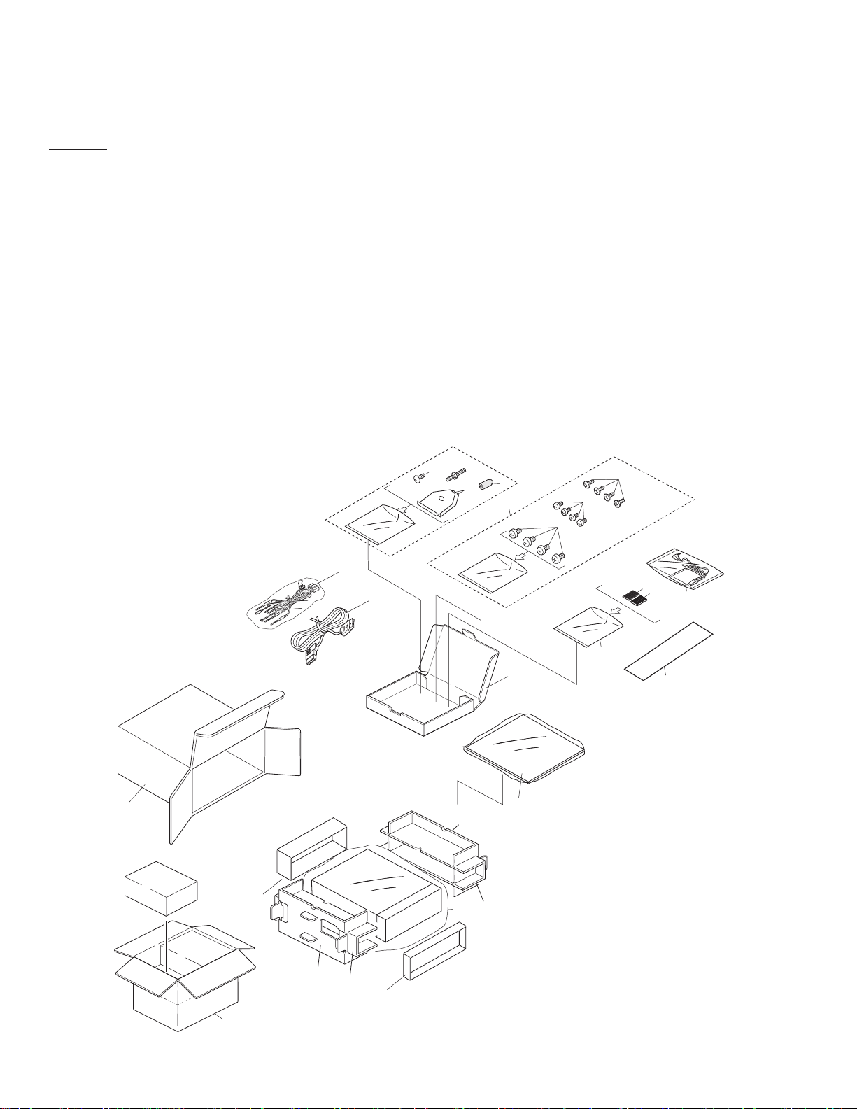
2. EXPLODED VIEWS AND PARTS LIST
2.1 PACKING
1. SAFETY INFORMATION
CAUTION
This service manual is intended for qualified service technicians; it is not meant for the casual do-it-yourselfer.
Qualified technicians have the necessary test equipment and tools, and have been trained to properly and safely repair
complex products such as those covered by this manual.
Improperly performed repairs can adversely affect the safety and reliability of the product and may void the warranty.
If you are not qualified to perform the repair of this product properly and safely, you should mot risk trying to do so
and refer the repair to a qualified service technician.
W
ARNING
This product contains lead in solder and certain electrical parts contain chemicals which are known to the state of
California to cause cancer, birth defects or other reproductive harm.
Health & Safety Code Section 25249.6 - Proposition 65
2
3
19
4
6
5
20
23
10
21
22
1
18
17
24
25
27
11
8
13
7
26
16
13
14
12
14
15
9
3
AVX-7300
NOTE:
- Parts marked by “*”are generally unavailable because they are not in our Master Spare Parts List.
- Screws adjacent to ∇ mark on the product are used for disassembly.
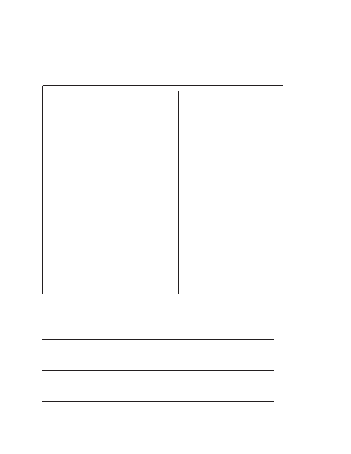
- PACKING SECTION PARTS LIST
- Owner's Manual and Installation Manual
Part No. Language
CRB1741 English
CRB1715 Spanish
CRB1716 German
CRB1742 French
CRB1718 Italian
CRB1719 Dutch
CRB1720 Arabic
CRB1721 Portuguese(B)
CRD3482 English,French
CRD3481 English,Spanish,Dutch,German,French,Italian
CRD3483 English,Spanish,Arabic,Portuguese(B)
Part No.
Mark No. Description AVX-7300/UC AVX-7300/EW AVX-7300/ES
1 Cord CDE6573 CDE6573 CDE6573
2 Accessory Assy CEA2876 CEA2876 CEA2876
3 Screw BPZ20P060FMC BPZ20P060FMC BPZ20P060FMC
4 Screw CBA1002 CBA1002 CBA1002
5 Bracket CNC9383 CNC9383 CNC9383
6 Bush CNV1917 CNV1917 CNV1917
7-1 Polyethylene Bag CEG1116 CEG1116 CEG1116
7-2 Owner's Manual CRB1741 CRB1741 CRB1741
7-3 Owner's Manual CRB1742 CRB1715 CRB1715
7-4 Owner's Manual Not used CRB1716 CRB1720
7-5 Owner's Manual Not used CRB1742 CRB1721
7-6 Owner's Manual Not used CRB1718 Not used
7-7 Owner's Manual Not used CRB1719 Not used
7-8 Installation Manual CRD3482 CRD3481 CRD3483
* 7-9 Card ARY1048 Not used Not used
* 7-10 Warranty Card Not used CRY1157 Not used
8 Carton CHG4405 CHG4407 CHG4406
9 Contain Box CHL4405 CHL4407 CHL4406
10 Screw(M4x3) CBA1468 CBA1468 CBA1468
11 Sub Box CHA3172 CHA3172 CHA3172
12 Polyethylene Bag CEG1173 CEG-162 CEG-162
13 Protector CHP2445 CHP2445 CHP2445
14 Protector CHP2446 CHP2446 CHP2446
15 Protector CHP2385 CHP2385 CHP2385
16 Protector CHP2386 CHP2386 CHP2386
* 17 Fastener CNM6544 CNM6544 Not used
* 18 Fastener CNM6545 CNM6545 Not used
* 19 Polyethylene Bag E36-615 E36-615 E36-615
20 Screw Assy CEA2927 CEA2927 CEA2927
21 Screw BMZ50P060FMC BMZ50P060FMC BMZ50P060FMC
* 22 Polyethylene Sheet CNM4338 CNM4338 CNM4338
23 Screw CMZ50P060FMC CMZ50P060FMC CMZ50P060FMC
24 Cord CDE6570 CDE6570 CDE6570
25 Speaker Unit CXB6699 CXB6699 Not used
26 Sheet CNM7244 CNM7244 CNM7244
27 Polyethylene Bag CEG1116 CEG1116 Not used

4
AVX-7300
2.2 EXTERIOR(1/3)
A
E

5
AVX-7300
1 Screw BMZ20P030FZK
2 •••••
3 Screw BMZ26P040FMC
4 Screw BSZ26P050FMC
5 Screw(M1.7x3) CBA1475
6 •••••
7 Resistor RS1/2P102JL
8 •••••
9 Cord CDE6573
10 Fuse(4A) CEK1001
11 Cap CNS1472
12 Screw CMZ50P060FMC
13 Case CNB2703
14 •••••
15 Bracket CNC9389
16 Holder CNC9510
17 Panel
See Contrast table(2)
18,19 •••••
20 Spring CBH2479
21,22 •••••
23 Spacer CNM7465
24 Spacer CNM7466
25,26 •••••
27 Panel
See Contrast table(2)
28 Control Unit
See Contrast table(2)
29 Screw BMZ26P200FMC
30 •••••
31 Transistor(Q33) 2SD2396
32 Cord CDE6568
33 Grille Unit
See Contrast table(2)
34 •••••
35 Cable CDE6575
36 Plug(CN401) CKM1187
37 Jack(CN202)
See Contrast table(2)
38 Plug(CN402) CKS-790
39-42 •••••
43 Connector(CN201) CKS3645
44 •••••
45 Connector(CN651) CKS3970
46 •••••
47 Grille Unit
See Contrast table(2)
48 Connector(CN101) CKS4495
49 •••••
50 Bracket CNC9371
51,52 •••••
53 Heat Sink CNR1609
54 Screw BPZ20P060FMC
55,56 •••••
57 Cover CNS6570
58 Button CAC6992
59 Button CAC6993
60 Button CAC6997
* 61 Cushion CNM6270
62-64 •••••
65 Keyboard Unit
See Contrast table(2)
66 Button
See Contrast table(2)
* 67 Badge CAH1786
68 Connector(CN1901) CKS4511
69 Spacer CNM7247
70-72 •••••
73 Button(RGB) CAC7004
74 Button(V.SRC) CAC7010
75 Detach Grille Assy
See Contrast table(2)
76,77 •••••
78 IC(IC1901) TSOP1840SB1
(1) EXTERIOR(1/3) SECTION PARTS LIST
Mark No. Description Part No.
Mark No. Description Part No.
(2) CONTRAST TABLE
AVX-7300/UC , AVX-7300/EW and AVX-7300/ES are constructed the same except for the following:
Part No.
Mark No. Description AVX-7300/UC AVX-7300/EW AVX-7300/ES
17 Panel CNC9691 CNC9691 CNC9704
27 Panel CNS6571 CNS6571 CNS6627
28 Control Unit CWM7742 CWM7741 CWM7743
33 Grille Unit CXB7281 CXB7281 CXB7282
37 Jack(CN202) CKN1027 CKN1027 Not used
47 Grille Unit CXB7286 CXB7286 CXB7287
65 Keyboard Unit CWM7747 CWM7746 CWM7747
66 Button CAC6994 CAC6994 CAC7011
75 Detach Grille Assy CXB7126 CXB7126 CXB7127
6
AVX-7300
G
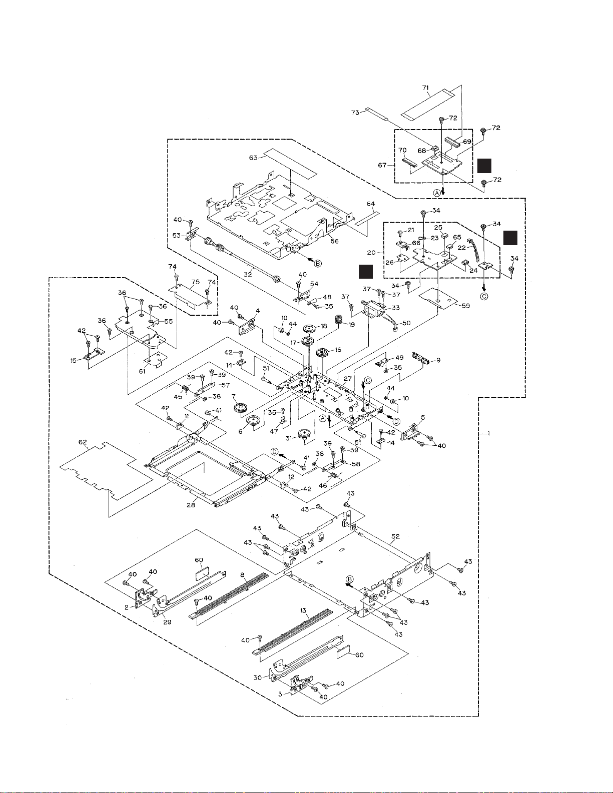
2.3 EXTERIOR(2/3)
C
F

7
AVX-7300
- EXTERIOR(2/3) SECTION PARTS LIST
Mark No. Description Part No.
Mark No. Description Part No.
1 Drive Unit CXB7323
2 Rail CNS6492
3 Rail CNS6493
4 Guide CNS6494
5 Guide CNS6495
6 Gear CNV6654
7 Gear CNV6655
8 Rack CNV6669
9 Guide CNV6672
10 Roller CNV6673
11 Guide CNV6750
12 Guide CNV6751
13 Rack CNV6752
14 Guide CNV6765
15 Guide CNV6766
16 Gear CNV6824
17 Gear CNV6825
18 Gear CNV6826
19 Gear CNV6827
20 Encoder Unit CWM7620
21 Screw BMZ26P050FMC
22 Cord Assy CDE6686
23 Terminal(CN2801) CKF1064
24 Connector(CN2804) CKS4054
25 Connector(CN2805) CKS4282
26 Heat Sink CNC9312
27 Frame Unit CXB7051
* 28 Case Unit CXB7052
29 Rail Unit CXB7064
30 Rail Unit CXB7065
31 Gear Unit CXB7437
32 Shaft Unit CXB7611
33
Motor Unit(M1)(Drive Motor)CXB7612
34 Screw IMS20P030FMC
35 Screw JFZ20P020FZK
36 Screw JFZ20P040FZK
37 Screw JGZ20P020FMC
38 Washer YE20FUC
39 Screw(M2x2.2) CBA1419
40 Screw(M2x2.5) CBA1447
41 Screw(M1.7x3) CBA1475
42 Screw(M2x2) CBA1484
43 Screw(M3x3) CBA1534
44 Washer CBF1064
45 Spring CBH2469
46 Spring CBH2470
47 Spring CBL1527
48 Spring CBL1534
49 Spring CBL1545
50 Cord Assy CDE6685
51 Shaft CLA4007
52 Chassis CNA2385
53 Holder CNC9302
54 Holder CNC9303
55 Cover CNC9304
56 Frame CNC9455
57 Holder CNC9516
58 Holder CNC9517
59 Insulator CNM7335
59 Insulator CNM7380
60 Cushion CNM7377
61 Insulator CNM7335
62 Sheet CNM7415
63 Insulator CNM7490
64 Insulator CNM7491
65 Connector(CN2806) CKS4282
66 IC(IC2801) TA7806S
67 Relay Unit CWM7752
68 Connector(CN1102) CKS4054
69 Connector(CN1103) CKS4495
70 Connector(CN1101) CKS4495
71 PCB CNP6440
72 Screw(M2x2.5) CBA1076
73 FFC CDE6555
74 Screw(UC,EW model) CBA1484
Screw(ES model) CBA1551
75 Cover CNC9467

8
AVX-7300
B
2.4 EXTERIOR(3/3)
D

9
AVX-7300
(1) EXTERIOR(3/3) SECTION PARTS LIST
Mark No. Description Part No. Mark No. Description Part No.
1 Connector(CN1301) CKS4448
2 Connector(CN2941) CKS4054
3 Connector(CN2942) CKS4428
4 LCD Module CWX2565
5 Holder CNC9500
6 Insulator CNM7351
7 Insulator CNM7352
8 Grille Unit
See Contrast table(2)
9 Sheet CNM7592
10 Sheet CNM7591
11 Button(WIDE/ANGLE) CAC7013
12 Button(OPEN/CLOSE) CAC7014
13 PCB CNP6272
14 Cover
See Contrast table(2)
15 Holder CNC9535
16 Screw
See Contrast table(2)
17 Control Unit
See Contrast table(2)
18 Keyboard Unit
See Contrast table(2)
19 Screw BPZ20P060FMC
20 Screw JFZ20P022FNI
21 Sheet CNM7593
22 Sheet CNM7594
(2) CONTRAST TABLE
AVX-7300/UC , AVX-7300/EW and AVX-7300/ES are constructed the same except for the following:
Part No.
Mark No. Description AVX-7300/UC AVX-7300/EW AVX-7300/ES
8 Grille Unit CXB7268 CXB7268 CXB7557
14 Cover CNS6628 CNS6628 CNS6564
16 Screw CBA1484 CBA1484 CBA1551
17 Control Unit CWM7742 CWM7741 CWM7743
18 Keyboard Unit CWM7747 CWM7746 CWM7747
H
2.5 LCD MODULE
- LCD MODULE SECTION PARTS LIST
Mark No. Description Part No.
1 LCD Module TFD70W80
2 Back Light Unit NML75-9252-P
3 Video Schematic NMP70-9253-P
- Please stop the reuse of this sheet when you peel off sheet(9,10,21,22).

10
AVX-7300
A
1
234
B
C
D
12
34
BUP BL+B
V+9V BUP
Q604
Q13
ILMPW
53
pwsave
35
SWVDD
39
VPW
41
adpw
6
AVREF0
75
pwsens
34
ILM+B
BUP
BUP
BUP
SWVDD
VDD
Q11
Q27
BLTPW
40
Q853
VDD
IC 604
M62354GP
Q23
Q24
Q203
Q26
SYSPW-M
55
Q34
Q33
Q25
9
RET H
10
RET V
17
PWRVI
13
SP+
16
SP-
CN201
1
R
2
G
3
B
IC 302
TC7W34FU
IC 602
PE5230A
MONITOR
CONTROL
7
5
1
3
IC 301
TC74HC123AF
49
IC 103
TC74VHCT08AFT
3
6
1
4
IC 101
NJM2903V
21
IC 309
NJM2235V
BZ601
71
IC 307
NJM2235V
17
IC 303
BA7071F
71
DIM
OSDCK/OSDCS/OSDDT
KEY0/KEY1/KEY2 KEY0/KEY1/KEY2
5
RGB/com
44
OSD
15
BEEP_M
45
VSYNC
61
LSENS
76
AVON
59
PBSENS
54
X1
70
X269KEY3
80
X601
4.19MHz
29
CN101 CN1103
R
30
G
31
B
27
HSY
26
VSY
HSY
VSY
DIM
VSEL
OSD
VIDEO
G
R
B
45
DIMMER
15
RGB/COM
21
OSD
33
46
V/SYNC
20
21
22
24
25
6
36
30
18
5
IC 605
TC74VHCT08AFT
Q1101
C
RELAY UNIT
Q404
Q653
CN651
CN401
CN1901
3
RGLED-B
10
11
REMIN
6
3
10
11
6
reset
reset
60
IC 603
S-80734ANDYI
RESET
1
2
VDD
Q851
TS
R
S
E
GR
asens
65
isens
37
bsens
66
2
5
12
11
1
2
3
CN402
COMP
6
LED _V
8
REMIN
5
AV_ON
AV BUS
CONNECTOR
A
CONTROL PCB
RGB
CONNECTOR
VBU,MTRPW,MTR,DEG
EW,ES
CN202
2
3
SPEAKER
Q603
Q403
1K(1/2W)
1K(1/2W)
ACC
ILM
6
P. B .
B.U.
GND
3
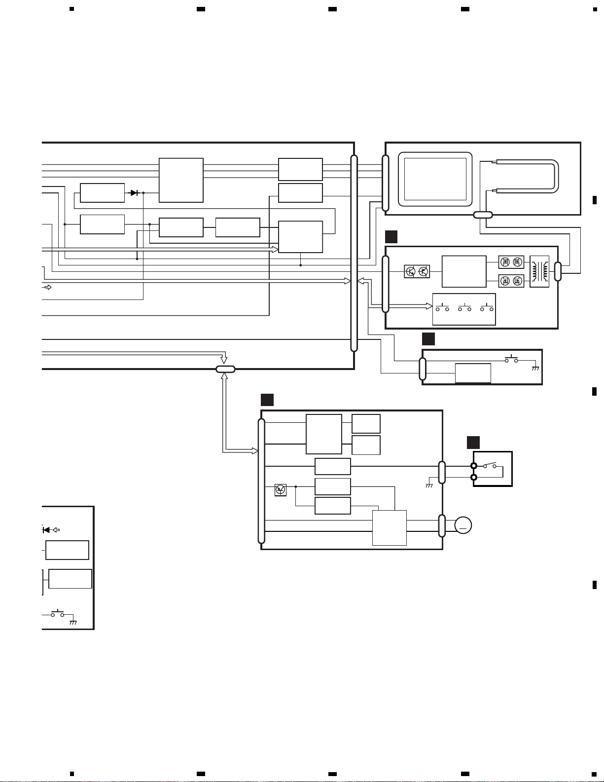
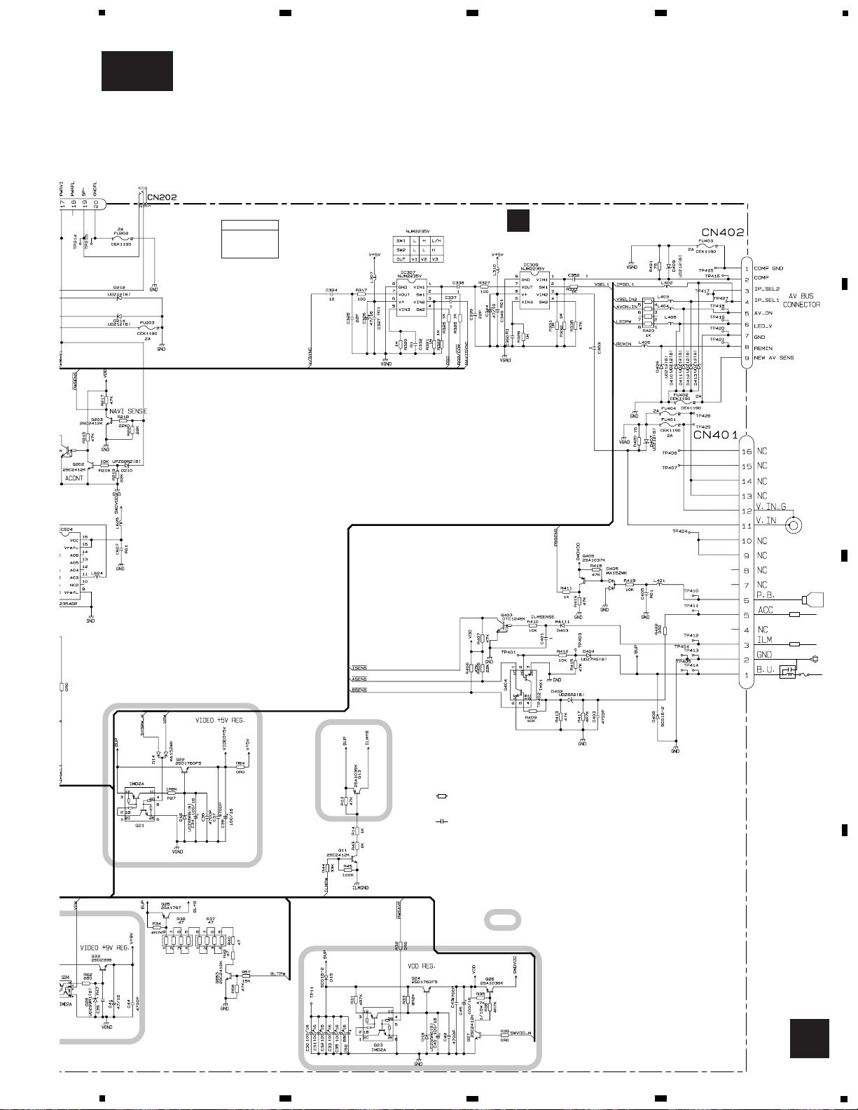
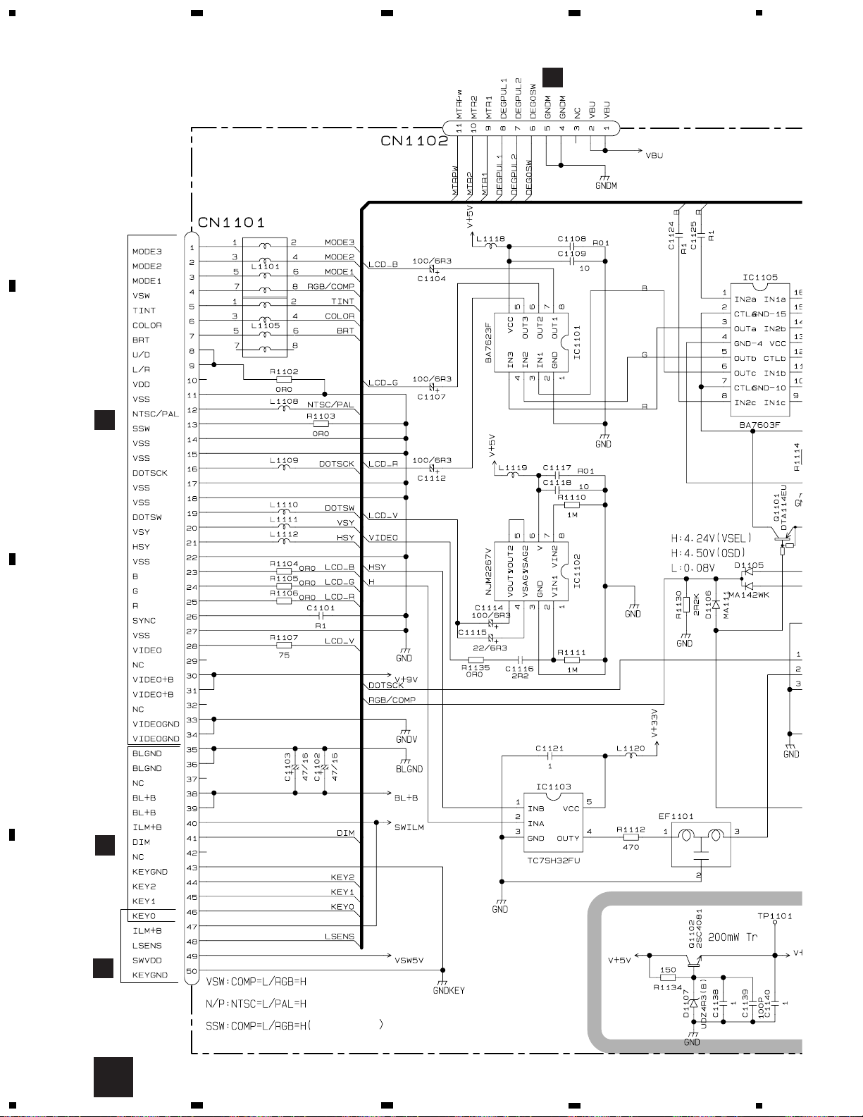
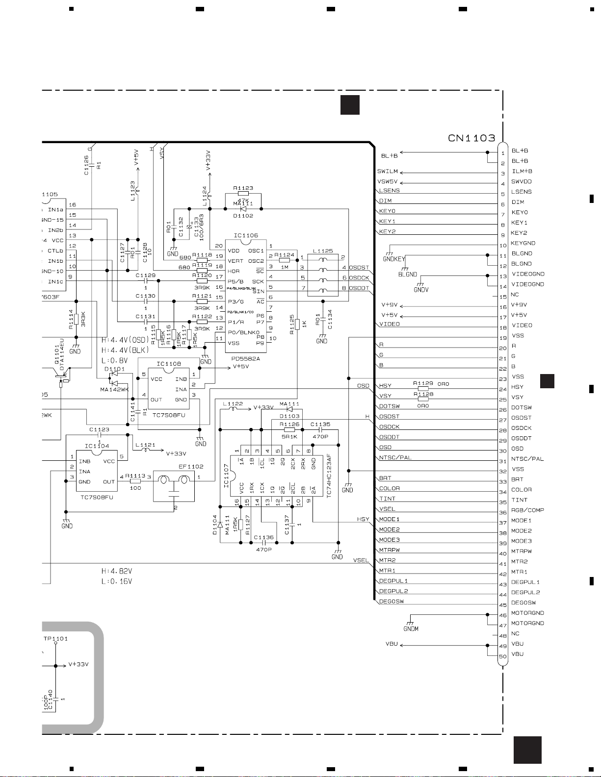
3. BLOCK DIAGRAM AND SCHEMATIC DIAGRAM
3.1 BLOCK DIAGRAM
11
AVX-7300
5
6
7
8
A
B
C
D
5
6
7
8
2
IC 1105
BA7603F
13
IC 1108
TC7S08FU
24
IC 1107
TC74HC123AF
94
IC 1103
TC7SH32FU
2
1
4
IC 1101
BA7623F
46
537
6
IC 1102
NJM2267V
2
8
13,4
12
R
14
G
8
2,7,
12
B
IC 1106
PD5582A
1,2
18
19
25
CN1101
CN2942
LCD_R
24
LCD_G
23
LCD_B
28
LCD_V
21
HSY
20
VSY
41
48
DIM
IC 1104
TC7S08FU
24
VCC
CN1102
LCD
LCD
BACK LIGHT
Q2941 Q2942
IC 2941
OZ960IS
7
12
Q2943
20
Q2944
S2942
DOWN UP MENU
S2944 S2943
T2941
CN2941
DIM
6
D
INVERTER PCB
LCD MODULE
IC 1901
TSOP1840SB1
KEY
MATRIX
RESET
ILM+B
S1902
GRILLE PCB
CN1301
3
1
B
PHOTO PCB
IC 1301
NJM062V
7
OPEN/CLOSE
S1301
CN2804
6
3
2
1,2
5
F
ENCODER PCB
IC2807
TC7W14FU
IC2806
GP1S25
712
4
IC2805
GP1S25
53
42
2
DRIVE SW
S2801
1
2
1
2
IC2804
TC7S14FU
12
IC2801
TA7806S
12
IC2802
TA78L05F
DEGPUL2
DEGPUL1
DEG0SW
G
SW PCB
CN2806
CN2805
CN2807
CN2808
Q2801
VBU
MTR1
MTR2
10
5
7
9
6
12
IC2803
BA6951FS
M
M1
Drive Motor

12
AVX-7300
A
1
234
B
C
D
12
34
EW,ES
EW,ES
MONITOR
MICRO COMPUTER
>
>
>
>
>
>
SYNC SEPARATOR
>
C
CN1103
E
CN1901
(EW)
A
3.2 CONTROL PCB(GUIDE PAGE)
Note: When ordering service parts, be sure to refer to “EXPLODED VIEWS AND PARTS LIST” or “ELECTRICAL
PARTS LIST”.
A-a A-b
A-aA-a
A-b A-b
A-b A-b
A-a A-a
Large size
SCH diagram
Guide page
Detailed page
A-a
13
AVX-7300
5
6
7
8
A
B
C
D
5
6
7
8
1K(1/2W)
1K(1/2W)
4A
CEK1001
:The power supply is shown with the mark ed box.
Decimal points for resistor
and capacitor fixed values
are expressed as :
2.2 2R2
0.022 R022
←
←
The > mark found on some component parts indicates
the importance of the safety factor of the part.
Therefore, when replacing, be sure to use parts of
identical designation.
Symbol indicates a resistor.
No differentiation is made between chip resistors and
discrete resistors.
NOTE :
Symbol indicates a capacitor.
No differentiation is made between chip capacitors and
discrete capacitors.
>
>
>
>
>
>
A
CONTROL PCB
Control Unit
Consists of
Control PCB
Photo PCB
>
A
A-b

14
AVX-7300
A
1
234
B
C
D
12
34
EW,ES
MONITOR
MICRO COMPUTER
>
SYNC SEPARATOR
>
CN1103
A-a
A-b
A-a
1

15
AVX-7300
5
6
7
8
A
B
C
D
5
6
7
8
EW,ES
MONITOR
MICRO COMPUTER
>
>
>
>
>
C
CN110
E
CN1901
(EW)
A-a
A-b
A-a
2
3

16
AVX-7300
A
1
234
B
C
D
12
34
1K(1/2W)
>
>
>
>
>
>
A
CONTROL PCB
Control Unit
Consists of
Control PCB
Photo PCB
A-a
A-b
A-b
1

17
AVX-7300
5
6
7
8
A
B
C
D
5
6
7
8
1K(1/2W)
1K(1/2W)
4A
CEK1001
:The power supply is shown with the mark ed box.
Decimal points for resistor
and capacitor fixed values
are expressed as :
2.2 2R2
0.022 R022
←
←
The > mark found on some component parts indicates
the importance of the safety factor of the part.
Therefore, when replacing, be sure to use parts of
identical designation.
Symbol indicates a resistor.
No differentiation is made between chip resistors and
discrete resistors.
NOTE :
Symbol indicates a capacitor.
No differentiation is made between chip capacitors and
discrete capacitors.
>
A-a
A-b
A-b
2
3

18
AVX-7300
A
1
234
B
C
D
12
34
OPEN/CLOSE
C
CN1101
B
PHOTO PCB
Control Unit
Consists of
Control PCB
Photo PCB
B
3.3 PHOTO PCB

19
AVX-7300
20
AVX-7300
A
1
234
B
C
D
12
34
L fixation always
D
CN2941
B
CN1301
LCD MODULE
F
CN2804
C
3.5 RELAY UNIT
H
CN001
21
AVX-7300
5
6
7
8
A
B
C
D
5
6
7
8
C
RELAY UNIT
A
CN101
C
 Loading...