

Page 1
INSTALLATION MANUAL
MANUEL D’INSTALLATION
<KYMFF/01D00000>
AVX-7300
Printed in Japan
Imprimé au Japon
<CRD3482-A> UC
Connecting the Units <ENGLISH>
Note:
• This unit is for vehicles with a 12-volt battery and
negative grounding. Before installing it in a recreational vehicle, truck, or bus, check the battery
voltage.
• To avoid shorts in the electrical system, be sure to
disconnect the ≠ battery cable before beginning
installation.
• Refer to the owner’s manual for details on
connecting the power amp and other units, then
make connections correctly.
• Secure the wiring with cable clamps or adhesive
tape. To protect the wiring, wrap adhesive tape
around them where they lie against metal parts.
• Route and secure all wiring so it cannot touch any
moving parts, such as the gear shift, handbrake and
seat rails. Do not route wiring in places that get
hot, such as near the heater outlet. If the insulation
of the wiring melts or gets torn, there is a danger of
the wiring short-circuiting to the vehicle body.
• Don’t pass the yellow lead through a hole into the
engine compartment to connect to the battery. This
will damage the lead insulation and cause a very
dangerous short.
• Do not shorten any leads. If you do, the protection
circuit may fail to work when it should.
• Never feed power to other equipment by cutting
the insulation of the power supply lead of the unit
and tapping into the lead. The current capacity of
the lead will be exceeded, causing overheating.
• When replacing fuse, be sure to use only fuse of
the rating prescribed on the fuse holder.
• If the RCA pin jack on the unit will not be used, do
not remove the caps attached to the end of the connector.
• If this unit is installed in a vehicle that does not
have an ACC (accessory) position on the ignition
switch, the red lead of the unit should be connected
to a terminal coupled with ignition switch ON/OFF
operations. If this is not done, the vehicle battery
may be drained when you are away from the vehicle for several hours. (Fig.1)
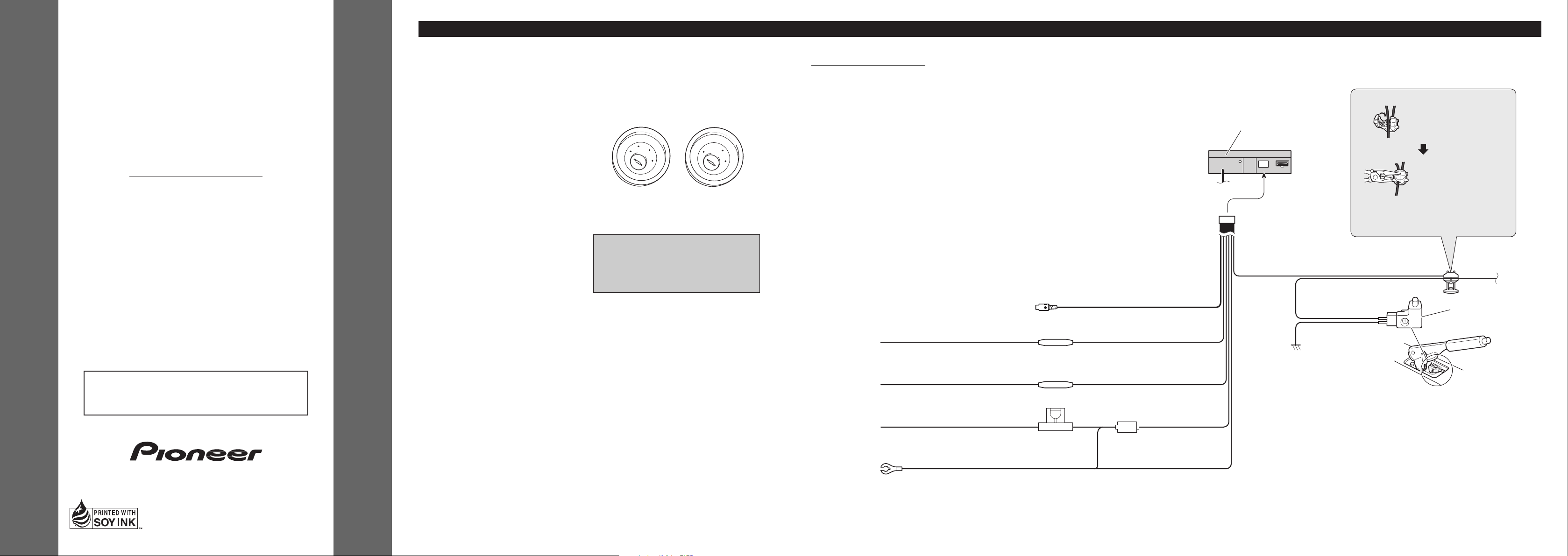
Fig. 1
No ACC positionACC position
This product conforms to CEMA cord colors.
Le code de couleur des câbles utilisé pour ce produit est
conforme à CEMA.
• Cords for this product and those for other products
may be different colors even if they have the same
function. When connecting this product to another
product, refer to the supplied Installation manuals
of both products and connect cords that have the
same function.
Light green
Used to detect the ON/OFF status of the parking brake.
This lead must be connected to the power supply side
of the parking brake switch.
Parking brake switch
Red
To electric terminal controlled by ignition
switch (12 V DC) ON/OFF.
Fuse resistor
Fuse holder
Black (ground)
To vehicle (metal) body.
Power supply side
Ground side
Connection method
2. Clamp firmly with
needle-nosed pliers.
Clamp the parking brake
switch power supply side
lead.
Note:
• The position of the parking brake switch depends
on the vehicle model. For details, consult the
vehicle Owner’s Manual or dealer.
This Product
1.
Yellow
To terminal always supplied with power
regardless of ignition switch position.
Yellow (video input)
(VIDEO INPUT)
15 cm
Fuse resistor
Orange/white
To lighting switch terminal.
Fig. 2
Connecting the Power Cord
C
C
A
O
F
O
N
F
S
T
A
R
T
O
F
N
F
O
S
T
A
R
T
Page 2
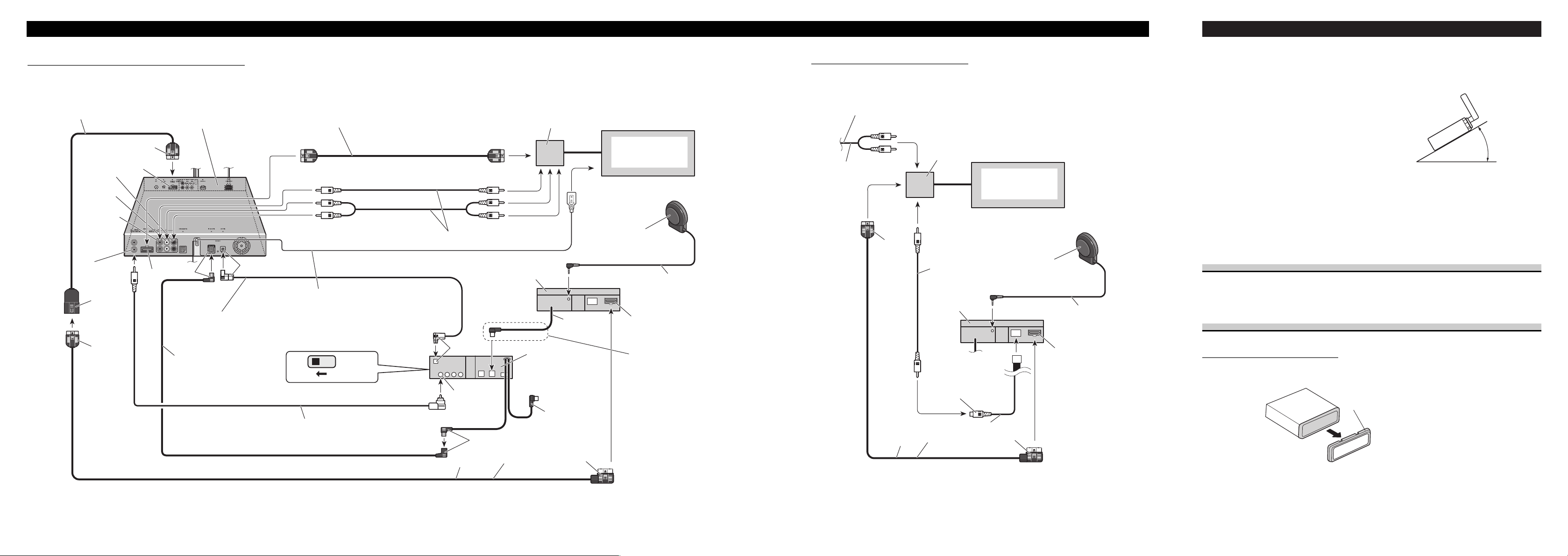
<ENGLISH>Connecting the Units
Multi-Channel AV
Master Unit (e.g. AVM-P9000R)
(sold separately)
Gray
Green
Gray
RCA cable (supplied with
the DVD player)
Blue
Yellow
(DVD VIDEO IN)
IP-BUS cable
(supplied with the Multi-Channel
AV Master Unit)
Optical cable
(supplied with the MultiChannel AV Master Unit)
3m
Black
Green
20 pin cable
(supplied)
Blue
Red
RCA cables (sold separately)
Green
Red
To audio outputs
To video output
RGB cable
(supplied with the MultiChannel AV Master Unit)
Red
Yellow
White (Left)
Red (Right)
AV cable
(supplied with the MultiChannel AV Master Unit)
Connection box
(supplied with the DVD
Navigation Unit)
DVD Navigation Unit
(e.g. AVIC-9DVD)
(sold separately)
This product
Voice guidance speaker
(supplied)
3m
DVD player
(e.g. SDV-P7)
(sold separately)
Red
Not used.
Blue
40 cm
Yellow (front
video output)
Yellow/black
ToYellow/black lead
(GUIDE ON)
on the navigation unit.
STAND ALONE
IP-BUS
Normally, connection is not
necessary.
If the DVD player (e.g. SDVP7) is installed in a location
that prevents reception of the
remote control signal, connect
with a separately sold AV-BUS
extension cable. (Or connect a
separately sold remote sensor
to the DVD player.)
When Connecting the Multi-Channel AV Master Unit
Fig. 3
3m
Green
20 pin cable
(supplied)
Red
RCA cable
(sold separately)
To video output
Yellow
(VIDEO INPUT)
Connection box
(supplied with the DVD
Navigation Unit)
DVD Navigation Unit
(e.g. AVIC-9DVD)
(sold separately)
This product
Voice guidance speaker
(supplied)
3m
Red
15 cm
To audio outputs
RCA cable
(sold separately)
To audio inputs of car stereo
When Connecting the Navigation Unit
Fig. 4
Installation <ENGLISH>
Note:
• Before finally installing the unit, connect the
wiring temporarily, making sure it is all connected
up properly, and the unit and the system work
properly.
• Use only the parts included with the unit to ensure
proper installation. The use of unauthorized parts
can cause malfunctions.
• Consult with your nearest dealer if installation
requires the drilling of holes or other modifications
of the vehicle.
• Install the unit where it does not get in the driver’s
way and cannot injure the passenger if there is a
sudden stop, like an emergency stop.
• Do not place the display in a position where it will
impede the driver’s visibility or affect the operation of your vehicle’s air bags.
• If installation angle exceeds 30° from horizontal,
the unit might not give its optimum performance.
(Fig. 5)
Fig. 5
DIN Front/Rear-mount
This unit can be properly installed either from “Front” (conventional DIN Front-mount) or
“Rear” (DIN Rear-mount installation, utilizing threaded screw holes at the sides of unit
chassis). For details, refer to the following illustrated installation methods.
DIN Front-mount
Installation with the rubber bush
1. Remove the frame. (Fig. 6)
Fig. 6
Frame
Pull out to remove the frame.
(When reattaching the frame, point the
side with a groove downwards and
attach it.)
30°
Page 3

<ENGLISH>Installation
7 When the installation space is not very deep
When installing in a shallow space, secure with side brackets (small). In this case, stick
conceal tape on parts that protrude from the dashboard.
Fig. 9
DIN Rear-mount
Installation using the screw holes on the side of the unit
1. Remove the frame. (Fig. 10)
Fig. 10
Frame
Pull out to remove the frame.
(When reattaching the frame, point the
side with a groove downwards and
attach it.)
Holder
After inserting the holder into the dashboard, then select the appropriate tabs
according to the thickness of the dashboard material and bend them.
(Install as firmly as possible using the
top and bottom tabs. To secure, bend
the tabs 90 degrees.)
182
53
Rubber bush
Screw
Dashboard
Attach screw
Side bracket
(small)
Conceal tape
Installing the Voice Guidance Speaker
Precaution:
• Do not install on the dashboard where it may be subjected to direct sunlight. High temperatures may
result in damage to the unit.
• Install within the transmission range of the remote control signal.
Stick the supplied velcro tapes to both the back of the voice guidance speaker and center
console, and attach them.
Fig. 13
Velcro tape
(rough surface)
Voice guidance speaker
Velcro tape
(soft surface)
2. Install side brackets. (Fig. 7)
Fig. 7
3. Fastening the unit. (Fig. 8)
As a rule, secure with side brackets (large).
Fig. 8
Holder
After inserting the holder into the dashboard, then select the appropriate tabs
according to the thickness of the dashboard material and bend them.
(Install as firmly as possible using the
top and bottom tabs. To secure, bend
the tabs 90 degrees.)
182
53
Rubber bush
Screw
Dashboard
Side bracket
(large)
Attach screw
Flush surface screw (5 × 6 mm)
Side bracket
2. Fastening the unit to the factory radio mounting bracket.
(Fig. 11) (Fig. 12)
Select a position where the screw holes of the bracket and the screw holes of this product
become aligned (are fitted), and tighten the screws at 2 places on each side. Use any of binding screws (4
× 3 mm), binding screws (5 × 6 mm) or flush surface screws (5 × 6 mm),
depending on the shape of the screw holes in the bracket.
*1 Use binding screws (4 × 3 mm) only.
Fig. 11
Fig. 12
*
1
*
1
Screw
Dashboard or Console
Factory radio mounting bracket
11
13
12
Page 4

Raccordements des appareils <FRANÇAIS>
Remarque:
• Cet appareil est destiné aux véhicules avec une batterie de 12 V, avec pôle négatif à la masse. Avant
de l’installer dans un véhicule de loisir, un camion
ou un car, vérifier la tension de la batterie.
• Afin d’éviter tout risque de court-circuit, débrancher le câble de la borne négative ≠ de la batterie
avant de commencer la pose.
• Pour le raccordement des câbles de l’amplificateur
de puissance et des autres appareils, se reporter au
manuel de l’utilisateur et procéder comme il est
indiqué.
• Fixer les câbles au moyen de colliers ou de
morceaux de ruban adhésif. Pour protéger le
câblage, enrouler la bande adhésive autour des
câbles à l’endroit où ceux-ci sont placés contre les
parties métalliques.
• Acheminer et fixer tout le câblage de telle sorte
qu’il ne touche pas les pièces mobiles, comme le
levier de changement de vitesse, le frein à main et
les rails des sièges. Ne pas acheminer les câbles
dans des endroits qui peuvent devenir chauds,
comme près de la sortie de radiateur. Si l’isolation
des câbles fond ou est se déchire, il existe un danger de court-circuit des câbles avec la carrosserie
du véhicule.
• Ne pas faire passer le conducteur jaune dans le compartiment moteur par un trou pour le connecter avec
la batterie. Cela pourrait endommager sa gaine d’isolation et provoquer un grave court-circuit.
• Ne pas court-circuiter les conducteurs. Dans le cas
contraire, le circuit de protection risque de ne pas
fonctionner.
• Ne jamais alimenter un autre appareil par un
branchement sur le câble d’alimentation de celui-ci.
Le courant qui circulerait dans ce conducteur pourrait dépasser la capacité du conducteur et entraîner
une élévation anormale de température.
• Lors du remplacement du fusible, n’utiliser qu’un
fusible de même ampérage (il est indiqué sur le
porte-fusible).
• Si la prise RCA de l’appareil n’est pas utilisée, ne
retirez pas les capuchons que porte le connecteur.
• Si cette unité est installée dans un véhicule dont le
contacteur d’allumage n’a pas de position ACC
(accessoire), le fil rouge de l’unité doit être connecté à une borne couplée aux opérations de
marche/arrêt du contacteur d’allumage. Sinon, la
batterie du véhicule peut se décharger lorsque le
véhicule n’est pas utilisé pendant plusieurs heures.
(Fig. 1)
Fig. 1
Aucune position ACCPosition ACC
• Les câbles de ce produit et ceux d’autres
produits peuvent fort bien ne pas être de la
même couleur bien que remplissant la même
fonction. Pour relier ce produit à un autre produit,
utilisez le manuel d’installation de chacun et
effectuez les raccordements en ne tenant compte
que de la fonction de chaque câble.
Branchement du cordon d’alimentation
S’éclaire de couleur verte
Utilisé pour détecter l’état ON/OFF du frein à main.
Ce conducteur doit être raccordé sur l’alimentation
du contacteur de frein à main.
Contacteur de
frein à main
Rouge
Vers une borne dont l’alimentation est
commandée par la clé de contact (12 V CC).
Résistance fusible
Porte-fusible
Noir (masse)
Fil de masse vers un élément en métal
apparent de la voiture.
Côté alimentation
Côté masse
Méthode de connexion
2. Serrez fermement avec
une pince à mâchoires
pointues.
Immobilisez le fil
d’alimentation du
contacteur de frein à
main.
Remarque:
• La position du contacteur de frein à main dépend
du modèle de véhicule. Pour les détails, consultez
le manuel de l’utilisateur du véhicule ou un
concessionnaire.
Cet appareil
1.
Jaune
Vers une borne alimentée en permanence
indépendamment de la clé de contact.
Jaune (Entrée vidéo)
(VIDEO INPUT)
15 cm
Résistance fusible
Orange/blanc
Vers la borne du contacteur d’éclairage.
Fig. 2
C
C
A
O
F
N
F
O
S
T
A
R
T
O
F
N
F
O
S
T
A
R
T
Page 5

Raccordements des appareils <FRANÇAIS>
3m
STAND ALONE
IP-BUS
3m
40 cm
Gris
Vert
Gris
Bleu
Câble IP-BUS
(fourni avec l’unité maîtresse
audiovisuel multicanaux)
Câble optique
(fourni avec l’unité maîtresse
audiovisuel multicanaux)
Noir
Vert
Câble à 20 broches
(fourni)
Bleu
Rouge
Câbles à fiches Cinch (RCA) (vendus séparément)
Vert
Rouge
Aux sorties audio
À la sortie vidéo
Câble RVB (fourni avec
l’unité maîtresse
audiovisuel multicanaux)
Rouge
Jaune
Blanc (gauche)
Rouge (droite)
Câble audio/vidéo
(fourni avec l’unité maîtresse
audiovisuel multicanaux)
Boîtier de raccordement
(fourni avec l’unité de
navigation DVD)
Cet appareil
Haut-parleur de guide
vocal (fourni)
Lecteur de DVD
(par ex. SDV-P7)
(vendu séparément)
Rouge
Non utilisé.
Bleu
Jaune (sortie
vidéo avant)
Unité maîtresse audiovisuel
multicanaux
(par ex. AVM-P9000R)
(vendue séparément)
Câble à fiches Cinch (RCA)
(fourni avec le lecteur de DVD)
Jaune/noir
Au fil jaune/noir
(GUIDE ON) de
l’unité de navigation.
Unité de navigation DVD
(par ex. AVIC-9DVD)
(vendue séparément)
Normalement, cette
connexion n’est pas
nécessaire.
Si le lecteur de DVD (par ex.
SDV-P7) est installé dans un
endroit d’où il ne peut pas
recevoir les signaux de la
télécommande, connectez le
câble d’extension AV-BUS
vendu séparément. (Ou
connectez au lecteur de DVD
un capteur de télécommande
vendu séparément.)
Jaune
(DVD VIDEO IN)
Lors du raccordement à l’usnité maîtresse audiovisuel multicanaux
Fig. 3
3m
Vert
Rouge
À la sortie vidéo
Jaune
(VIDEO INPUT)
Boîtier de raccordement
(fourni avec l’unité de
navigation DVD)
Cet appareil
Haut-parleur de guide
vocal (fourni)
3m
Rouge
15 cm
Aux sorties audio
Aux prises d’entréedel’autoradio
Câble à fiches Cinch (RCA)
(vendu séparément)
Unité de navigation DVD
(par ex. AVIC-9DVD)
(vendue séparément)
Câble à fiches
Cinch (RCA)
(vendu
séparément)
Câble à 20 broches
(fourni)
Lors de la connexion de l’unité de navigation
Fig. 4
Remarque:
• Avant de finaliser l’installation de l’appareil, connecter temporairement le câblage en s’assurant que
tout est correctement connecté et que l’appareil et
le système fonctionnement correctement.
• Pour obtenir une bonne installation, n’utiliser que
les pièces de l’appareil. L’utilisation de pièces non
prévues risque de causer un mauvais fonctionnement.
• Consulter le concessionnaire le plus proche si l’installation nécessite le percement de trous ou toute
autre modification du véhicule.
• Installer l’appareil à un endroit où il ne gêne pas le
conducteur et où il ne peut pas blesser les passagers en cas d’arrêt brusque, comme pendant un
arrêt d’urgence.
• Ne placez pas l’écran dans une position où il peut
gêner la visibilité du conducteur ou affecter le bon
fonctionnement des sacs gonflables de protection.
• L’angle de l’installation, ne doit pas dépasser 30°
par rapport à l’horizontale, faute de quoi l’unité ne
fournira pas ses performances optimales.
(Fig. 5)
Fig. 5
Montage DIN avant/arrière
Cet appareil peut être convenable installé en choisissant soit la méthode habituelle de montage par “l’avant” (montage DIN avant), soit la méthode de montage par “l’arrière” (montage DIN arrière faisant appel aux perçages filetés de chaque côté du châssis). Pour de plus
amples détails concernant cette question, reportez-vous aux illustrations qui suivent.
Montage DIN avant
Installation avec une bague en caoutchouc
1. Déposez le cadre. (Fig. 6)
Fig. 6
Tirez pour enlever le cadre. (Pour
remettre le cadre en place, dirigez le côté
avec la rainure vers le bas.)
Cadre
Installation <FRANÇAIS>
30°
Page 6

<FRANÇAIS>Installation
2. Installez les supports latéraux. (Fig. 7)
Fig. 7
3. Fixez fermement l’appareil. (Fig. 8)
En règle générale, fixez d’abord le support latéral (grand).
Fig. 8
Support
Après avoir introduit le support dans le
tableau de bord, sélectíonnez les
languettes appropriées en fonction de
l’épaisseur du matériau du tableau de
bord et courbez-les.
(Assurez le maintien aussi solidement
que possible en utilisant les languettes
inférieures et supérieures. Cela fait,
courbez les languettes de 90 degrés.)
182
53
Bague en caoutchouc
Vis
Tableau de bord
Vis de fixation
Support latéral
(grand)
Support latéral
Vis à tête plate (5 × 6 mm)
7 Lors de l’installation dans une cavité peu profonde
Lors de l’installation dans une cavité peu profonde, fixez avec les supports latéraux (petits).
Dans ce cas, collez du ruban adhésif de masquage sur les parties qui dépassent du tableau de
bord.
Fig. 9
Montage DIN arrière
Installation de l’appareil en faisant appel aux perçages filetés pratiqués sur les faces latérales
1. Déposez le cadre. (Fig. 10)
Fig. 10
Tirez pour enlever le cadre. (Pour
remettre le cadre en place, dirigez le côté
avec la rainure vers le bas.)
Cadre
Support
Après avoir introduit le support dans le
tableau de bord, sélectíonnez les
languettes appropriées en fonction de
l’épaisseur du matériau du tableau de
bord et courbez-les.
(Assurez le maintien aussi solidement
que possible en utilisant les languettes
inférieures et supérieures. Cela fait,
courbez les languettes de 90 degrés.)
182
53
Bague en caoutchouc
Vis
Tableau de bord
Vis de fixation
Ruban adhésif de masquage
Support latéral
(petit)
2. Fixation de l’appareil au support de montage d’autoradio pourvu par l’usine.
(Fig. 11) (Fig. 12)
Choisissez une position telle que les perçages de vis du support soient en regard (face à face)
des perçages de vis de l’appareil puis mettez en place 2 vis de chaque côté de l’appareil.
Selon la forme du perçage du support, utilisez les vis de pression de 4
× 3 mm, les vis de
pression de 5
× 6 mm ou les vis à tête plate de 5 × 6 mm.
*1 N’utilisez que les vis de pression de 4 × 3 mm.
Fig. 11
Fig. 12
*
1
*
1
Installation du haut-parleur de guide vocal
Précaution:
• N’installez pas le capteur sur le tableau de bord où il peut être exposé à la lumière directe du soleil.
Les températures élevées peuvent endommager l’appareil.
• Installez le capteur dans la plage de transmission du signal de télécommande.
Collez la bande Velcro fournie à l’arrière du haut-parleur de guide vocal et sur la console
centrale, et attachez-les.
Fig. 13
Bande Velcro
(surface rugueuse)
Bande Velcro
(surface lisse)
Haut-parleur de guide vocal
Vis
Tableau de bord ou console
Support de montage d’autoradio usine
11
13
12
 Loading...