

Page 1

AVX-7300
ENGLISH ESPAÑOL
MANUEL D’INSTALLATION
DEUTSCH
FRANÇAIS
This product conforms to new cord colors.
Los colores de los cables de este producto se conforman con un nuevo código de colores.
Dieses Produkt entspricht den neuen kabelfarben.
Le code de couleur des câbles utilisé pour ce produit est
nouveau.
Questo prodotto è conforme ai nuovi codici colori.
De kleuren van de snoeren van dit toestel zijn gewijzigd.
INSTALLATION MANUAL
ITALIANO
NEDERLANDS
Page 2

Contents
Connecting the Units ................................ 2
-
Connecting the Power Cord
-
When Connecting the Multi-Channel AV
Master Unit
-
When Connecting the Navigation Unit
Installation .................................................. 8
DIN Front/Rear-mount ...................................... 8
DIN Front-mount .............................................. 8
-
Installation with the rubber bush
DIN Rear-mount .............................................. 10
-
Installation using the screw holes on
the side of the unit
Installing the Voice Guidance Speaker .......... 12
1
Page 3

Connecting the Units
Note:
• This unit is for vehicles with a 12-volt battery and
negative grounding. Before installing it in a recreational vehicle, truck, or bus, check the battery
voltage.
• To avoid shorts in the electrical system, be sure to
disconnect the ≠ battery cable before beginning
installation.
• Refer to the owner’s manual for details on connecting the power amp and other units, then make
connections correctly.
• Secure the wiring with cable clamps or adhesive
tape. To protect the wiring, wrap adhesive tape
around them where they lie against metal parts.
• Route and secure all wiring so it cannot touch any
moving parts, such as the gear shift, handbrake,
and seat rails. Do not route wiring in places that
get hot, such as near the heater outlet. If the insulation of the wiring melts or gets torn, there is a
danger of the wiring short-circuiting to the vehicle
body.
• Don’t pass the yellow lead through a hole into the
engine compartment to connect to the battery.
This will damage the lead insulation and cause a
very dangerous short.
• Do not shorten any leads. If you do, the protection
circuit may fail to work when it should.
• Never feed power to other equipment by cutting
the insulation of the power supply lead of the unit
and tapping into the lead. The current capacity of
the lead will be exceeded, causing overheating.
• When replacing fuse, be sure to use only fuse of
the rating prescribed on the fuse holder.
• If the RCA pin jack on the unit will not be used,
do not remove the caps attached to the end of the
connector.
• If this unit is installed in a vehicle that does not
have an ACC (accessory) position on the ignition
switch, the red lead of the unit should be connected to a terminal coupled with ignition switch
ON/OFF operations. If this is not done, the vehicle battery may be drained when you are away
from the vehicle for several hours. (Fig. 1)
C
C
A
O
F
N
F
O
S
T
A
R
T
O
F
N
F
O
S
T
A
R
T
No ACC positionACC position
Fig. 1
• Cords for this product and those for other products may be different colors even if they have
the same function. When connecting this product
to another product, refer to the supplied
Installation manuals of both products and connect cords that have the same function.
ENGLISH ESPAÑOL DEUTSCH FRANÇAIS ITALIANO NEDERLANDS
2
Page 4
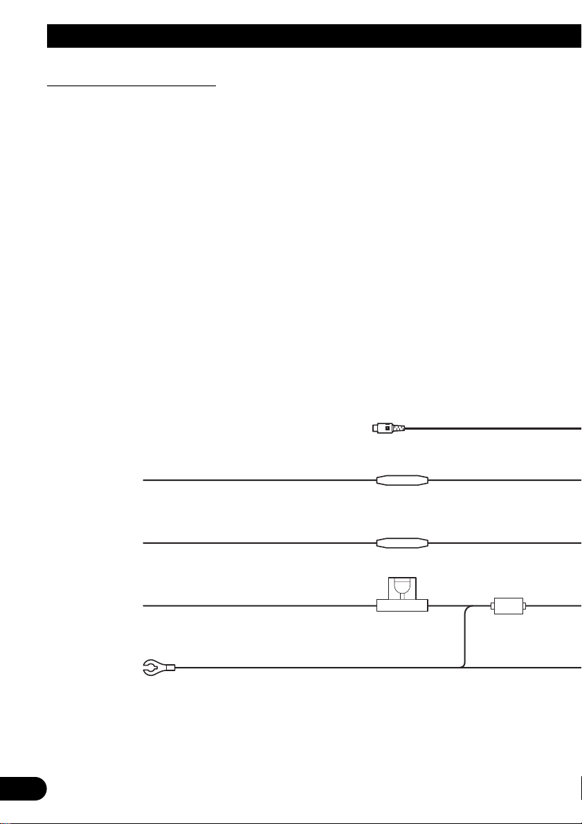
Connecting the Units
Red
Toelectric terminal controlled by ignition
switch (12V DC) ON/OFF.
Fuse resistor
Fuse holder
Black (ground)
Tovehicle (metal) body.
Yellow
Toterminal always supplied with power
regardless of ignitionswitch position.
Yellow (video input)
(VIDEO INPUT)
15 cm
Fuse resistor
Orange/white
Tolighting switch terminal.
Connecting the Power Cord
3
Page 5
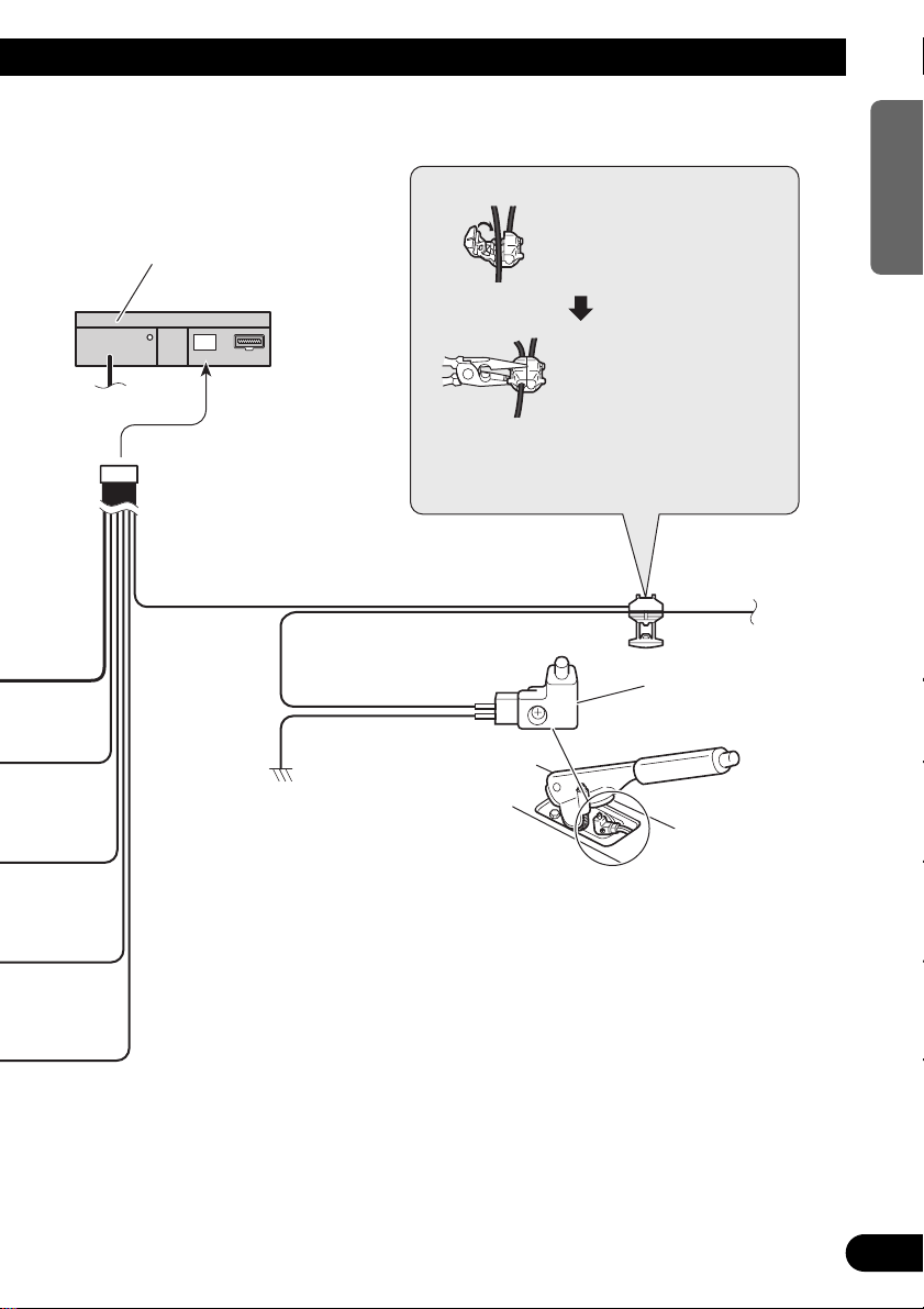
Light green
Used to detect the ON/OFF status of the parking brake.
This lead must be connected to the power supply side
of the parking brake switch.
Parking brake switch
Power supply side
Ground side
Connection method
2. Clamp firmly with
needle-nosed pliers.
Clamp the parking brake
switch power supply side
lead.
Note:
• The position of the parking brake switch depends
on the vehicle model. For details, consult the
vehicle Owner’s Manual or dealer.
This Product
1.
ENGLISH ESPAÑOL DEUTSCH FRANÇAIS ITALIANO NEDERLANDS
Fig. 2
4
Page 6

Connecting the Units
Multi-Channel AV
Master Unit (e.g. AVM-P9000R)
(sold separately)
Gray
Green
Gray
RCAcable (supplied with
the DVD player)
Blue
Yellow
(DVDVIDEO IN)
IP-BUS cable
(supplied with the Multi-Channel
AV Master Unit)
Optical cable
(supplied with the MultiChannel AV Master Unit)
Green
Blue
Red
RGB cable
(supplied with the MultiChannel AV Master Unit)
Red
Yellow
White (Left)
Red (Right)
AV cable
(supplied with the MultiChannel AV Master Unit)
Yellow/black
ToYellow/black lead
(GUIDE ON)
on the navigation unit.
STAND ALONE
IP-BUS
When Connecting the Multi-Channel AV Master Unit
5
Page 7

3m
Black
20 pin cable
(supplied)
Red
RCAcables (sold separately)
Green
Toaudio outputs
Tovideo output
Connection box
(supplied with the DVD
Navigation Unit)
DVD Navigation Unit
(e.g. AVIC-9DVD)
(sold separately)
This product
Voice guidance speaker
(supplied)
3m
DVD player
(e.g. SDV-P7)
(sold separately)
Red
Not used.
Blue
40 cm
Yellow (front
video output)
Not used.
ENGLISH ESPAÑOL DEUTSCH FRANÇAIS ITALIANO NEDERLANDS
Fig. 3
6
Page 8

Connecting the Units
3m
Green
20 pin cable
(supplied)
Red
RCAcable
(sold separately)
Tovideo output
Yellow
(VIDEO INPUT)
Connection box
(supplied with the DVD
Navigation Unit)
DVD Navigation Unit
(e.g. AVIC-9DVD)
(sold separately)
This product
Voice guidance speaker
(supplied)
3m
Red
15 cm
Toaudio outputs
RCAcable
(sold separately)
Toaudio inputs of car stereo
When Connecting the Navigation Unit
Fig. 4
7
Page 9

Installation
Frame
Pull out to remove the frame.
(When reattaching the frame, point the
side with a groove downwards and
attach it.)
Note:
• Before finally installing the unit, connect the
wiring temporarily, making sure it is all connected up properly, and the unit and the system work
properly.
• Use only the parts included with the unit to ensure
proper installation. The use of unauthorized parts
can cause malfunctions.
• Consult with your nearest dealer if installation
requires the drilling of holes or other modifications of the vehicle.
• Install the unit where it does not get in the driver’s way and cannot injure the passenger if there
is a sudden stop, like an emergency stop.
• Do not place the display in a position where it
will impede the driver’s visibility or affect the
operation of your vehicle’s air bags.
• If installation angle exceeds 30° from horizontal,
the unit might not give its optimum performance.
(Fig. 5)
DIN Front/Rear-mount
This unit can be properly installed either from “Front” (conventional DIN Front-mount) or
“Rear” (DIN Rear-mount installation, utilizing threaded screw holes at the sides of unit
chassis). For details, refer to the following illustrated installation methods.
ENGLISH ESPAÑOL DEUTSCH FRANÇAIS ITALIANO NEDERLANDS
30¡
Fig. 5
DIN Front-mount
Installation with the rubber bush
1. Remove the frame. (Fig. 6)
Fig. 6
8
Page 10

Installation
Holder
After inserting the holder into the dashboard, then select the appropriate tabs
according to the thickness of the dashboard material and bend them.
(Install as firmly as possible using the
top and bottom tabs. To secure, bend
the tabs 90 degrees.)
182
53
Rubber bush
Screw
Dashboard
Side bracket
(large)
Attach screw
Flush surface screw (5 ´ 6 mm)
Side bracket
2. Install side brackets. (Fig. 7)
3. Fastening the unit. (Fig. 8)
As a rule, secure with side brackets (large).
Fig. 7
9
Fig. 8
Page 11

7 When the installation space is not very deep
Frame
Pull out to remove the frame.
(When reattaching the frame, point the
side with a groove downwards and
attach it.)
Holder
After inserting the holder into the dashboard, then select the appropriate tabs
according to the thickness of the dashboard material and bend them.
(Install as firmly as possible using the
top and bottom tabs. To secure, bend
the tabs 90 degrees.)
182
53
Rubber bush
Screw
Dashboard
Attach screw
Side bracket
(small)
Conceal tape
When installing in a shallow space, secure with side brackets (small). In this case, stick
conceal tape on parts that protrude from the dashboard.
DIN Rear-mount
ENGLISH ESPAÑOL DEUTSCH FRANÇAIS ITALIANO NEDERLANDS
Fig. 9
Installation using the screw holes on the side of the unit
1. Remove the frame. (Fig. 10)
Fig. 10
10
Page 12

Installation
*
1
*
1
2. Fastening the unit to the factory radio mounting bracket.
(Fig. 11) (Fig. 12)
Select a position where the screw holes of the bracket and the screw holes of this product
become aligned (are fitted), and tighten the screws at 2 places on each side. Use any of
binding screws (4 ´ 3 mm), binding screws (5 ´ 6 mm) or flush surface screws (5 ´ 6
mm), depending on the shape of the screw holes in the bracket.
*1 Use binding screws (4 ´ 3 mm) only.
Screw
11
Fig. 11
11
Factory radio mounting bracket
12
Dashboard or Console
13
Fig. 12
Page 13

Installing the Voice Guidance Speaker
Velcro tape
(rough surface)
Voice guidance speaker
Velcro tape
(soft surface)
Precaution:
• Do not install on the dashboard where it may be subjected to direct sunlight. High temperatures
may result in damage to the unit.
• Install within the transmission range of the remote control signal.
Stick the supplied velcro tape to the back of both the voice guidance speaker and the center
console, and attach them.
ENGLISH ESPAÑOL DEUTSCH FRANÇAIS ITALIANO NEDERLANDS
Fig. 13
12
Page 14

France: tapez 36 15 PIONEER
PIONEER CORPORATION
4-1, MEGURO 1-CHOME, MEGURO-KU, TOKYO 153-8654, JAPAN
PIONEER ELECTRONICS (USA) INC.
P.O. Box 1760, Long Beach, California 90801, U.S.A.
TEL: (800) 421-1404
PIONEER EUROPE NV
Haven 1087, Keetberglaan 1, B-9120 Melsele, Belgium
TEL: (0) 3/570.05.11
PIONEER ELECTRONICS AUSTRALIA PTY. LTD.
178-184 Boundary Road, Braeside, Victoria 3195, Australia
TEL: (03) 9586-6300
PIONEER ELECTRONICS OF CANADA, INC.
300 Allstate Parkway, Markham, Ontario L3R OP2, Canada
TEL: (905) 479-4411
PIONEER ELECTRONICS DE MEXICO, S.A. de C.V.
San Lorenzo 1009 3er. Piso Desp. 302
Col. Del Valle Mexico, D.F. C.P. 03100
TEL: 5-688-52-90
Published by Pioneer Corporation.
Copyright © 2001 by Pioneer Corporation.
All rights reserved.
Publication de Pioneer Corporation.
Copyright © 2001 Pioneer Corporation.
Tous droits de reproduction et de traduction
réservés.
Printed in Japan
Imprimé au Japon
<CRD3481-A> EW<KYMFF/01D00000>
 Loading...