

Emergency Stop Relays, Safety Gate Monitors
Category 4, EN 954-1
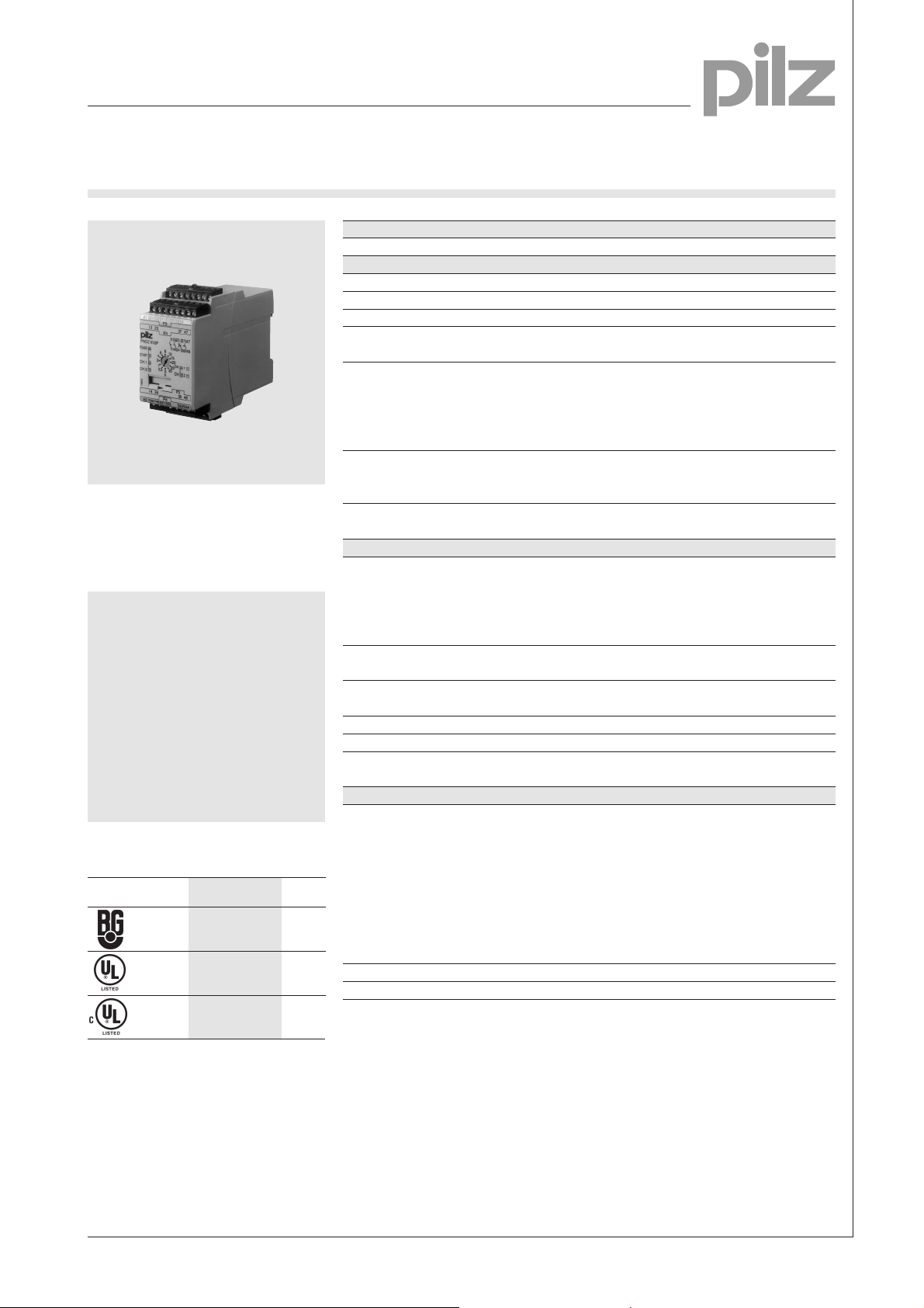
PNOZ XV2P
Technical Details PNOZ XV2P
Electrical data
Supply voltage 24 VDC
Tolerance 85 ... 110 %
Emergency stop relay and safety
gate monitor in accordance with
VDE 0113 Part 1, 11/98, EN 60204-1,
12/97 and IEC 204-1, 12/98
Features
● Circuit compatible with
PNOZ X3
● Dual-channel operation which
detects shorts across the inout
contacts
● Monitored manual or automatic
reset
● 2 delay-off safety contacts
● Supply voltage: 24 VDC
● Plug-in connection terminals
Approvals
PNOZ XV2P
Applied for
●
Power consumption U
Voltage and current at input 24 V DC, 50 mA
reset circuit and feedback control loop
Switching capability in accordance with
EN 60947-4-1, 10/91 AC1: 240 V/8 A/2000 VA
EN 60947-5-1, 10/91 AC15: 230 V/5 A; DC13: 24 V/7 A
(DC13: 6 switching cycles/min)
Output contacts 2 delay-off safety contacts (N/0 contact)
Contact fuse protection 10 A quick or 6 A slow
EN 60947-5-1, 10/91
Times
Delay time 37-38 and 47-48 adjustable:
Delay-on energisation monitored manual reset: max. 100 ms
Delay-on de-energisation with emergency stop: max. 50 ms
Recovery time approx. 1 s
Simultaneity channel 1/2 ¥
Max. supply interruption before
de-energisation Approx. 25 ms
Mechanical data
Max. cross-section of external conductor
Single-core
Multi-core (2 cores of equal cross-section) flexible with crimp connector, without
Dimensions (H x W x D) 94 x 45 x 121 mm
Weight 370 g
B
Approx. 4.5 W
DC1: 24 V/8 A/200 W
2 instantaneous safety contacts (N/0
contact)
0.1-3 s: 0.1/0.2/0.3/0.4/0.5/0.6/0.7/0.8/
1/1.5/2/3 s
0-30 s: 0/0.5/1/2/4/6/8/10/15/20/25/30 s
fixed: 0.5 s, 1 s, 10 s
automatic or manual reset: max. 0.5 s
power failure: max. 0.5 s
flexible without crimp connector:
0.2 ... 2.5 mm
flexible with crimp connector:
0.25 ... 2.5 mm
plastic sleeve: 0.25 ... 1 mm
flexible with TWIN crimp connector with
plastic sleeve: 0.5 ... 1.5 mm
1
2
2
2
2
●
Description
● LEDs for switching status
channel 1 / 2, reset circuit and
● 45 mm P-99 housing,
DIN -Rail mounting
● Positive-guided relay outputs:
– 2 safety contacts
supply voltage
● Increase in the number
of contacts available by
connecting expander modules
instantaneous (N/0 contact)
– 2 safety contacts
Operating modes
delay-off (N/0 contact)
● Connections for
– E-STOP button
– safety gate limit switch
– reset button
● Single-channel operation
● Dual-channel operation
● Automatic reset
● Monitored manual reset
NSG-D-2-247-12/00
Emergency Stop Relays, Safety Gate Monitors
Category 4, EN 954-1
PNOZ XV2P
Internal wiring diagram
B
U
Time reset
A2
A1
-
+
Y39Y40
CH2
S21
Input circuit
External wiring
● Example 1
Single-channel emergency stop
wiring with automatic reset
S11 S31
S21
S13
Y39
S1
S13S14 S12
Start
Unit
Input circuit
S11
CH1
S22
Safety
contacts
S32S31
13
K1
K2
14
Start and feedback control loop
S33
S34 47
● Example 4
Single-channel safety gate control
with monitored manual reset
S11
S21
S1
– Key
S1/S2: Emergency stop or safety
23
37
K3
K4
24
38
48
Y39
S33
S31
S3
S3: Reset button
gate switch
Switch operated
Gate open
Gate closed
S32
S12
S22
S14
Y40
● Example 2
Single-channel emergency stop
wiring with monitored manual reset
S11 S31
S21
Y39
S33
S1
S12
S32
S22
S3
Y40
S34
● Example 3
Dual-channel emergency stop wiring
with monitored manual reset
S21 S11
S31
S1
Y39
S33
S3
S32
S12
S22
S34
Y40
● Example 5
Dual-channel safety gate control with
monitored manual reset
Y39
S33
S11
S21
S1
S22
S3
S31
S2
S32
S12
S34
Y40
● Example 6
Dual-channel safety gate control with
automatic reset
S21
S13
S22
S31
Y39
S11
S1
S2
S22
S32
S12
S34
Y40
S32
S14
S12
Y40
NSG-D-2-247-12/00
Emergency Stop Relays, Safety Gate Monitors
Category 4, EN 954-1
PNOZ XV2P
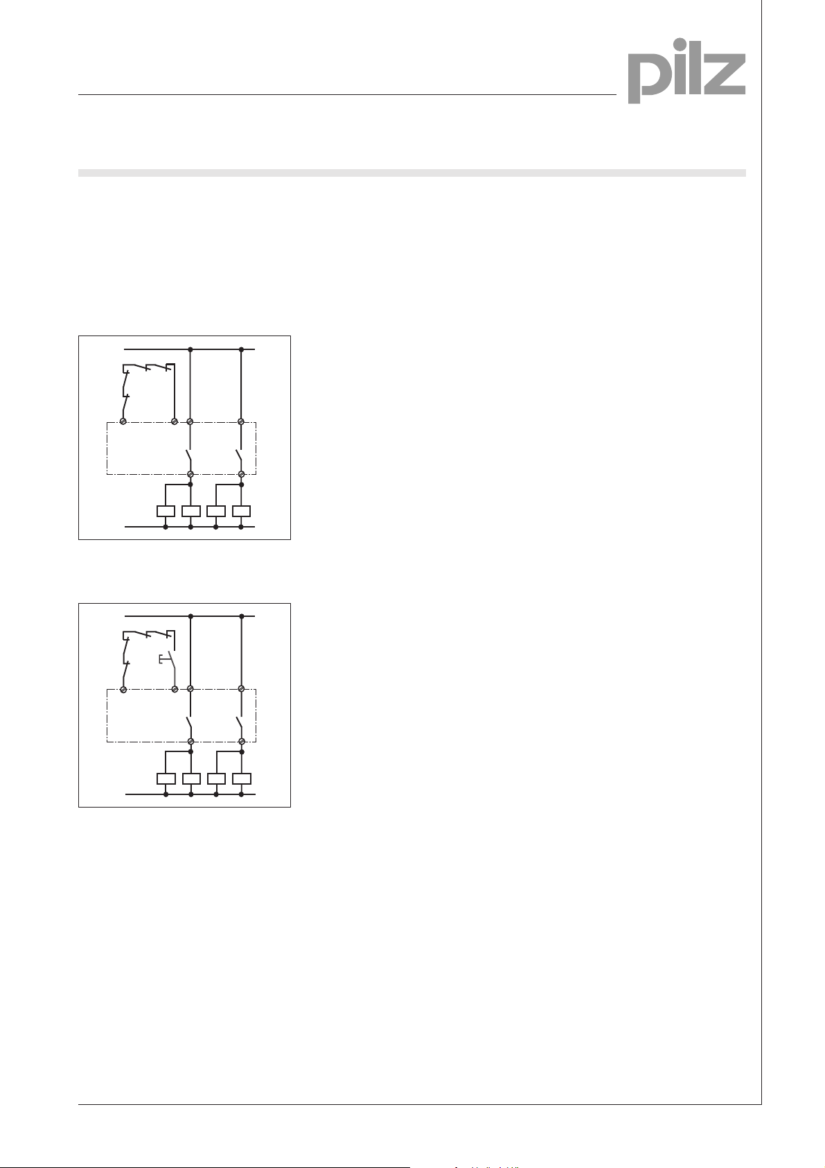
● Increase in safety contacts
The number of output contacts can
be increased by using expander
modules or contactors with positiveguide contacts.
– Operation with automatic reset
1L1
K7
K8
S13
1L2
K5
K6
13
S14
14
K5
K6
37
38
K8
K7
– Control with monitored manual
reset
1L1
K7
K8
S34
K5
K6
S3
S33
13
37
1
1L2
14
K5
K6
38
K8
K7
NSG-D-2-247-12/00

Emergency Stop Relays, safety door monitors
Category 4, EN 954-1
PNOZ XV2P
General Technical Data
Unless stated otherwise in the technical details for the specific unit
Electrical Data
Frequency Range AC 50 ... 60 Hz
Residual Ripple DC 160 %
Contact Material AgSnO
Continuous Duty 100 %
Environmental Data
EMC EN 50081-1, 01/92, EN 50082-2, 03/95
Vibration in accordance with Frequency: 10 ... 55 Hz,
EN 60068-2-6, 04/95 Amplitude: 0.35 mm
Climatic Suitability DIN IEC 60068-2-3, 12/86
Airgap Creepage DIN VDE 0110 part 1, 04/97
Ambient Temperature -10 ... +55 °C
Storage Temperature -40 ... +85 °C
Mechanical Data
Torque Setting on Connection Terminals 0.6 Nm (screws)
Mounting Position Any
Housing Material Thermoplast Noryl SE 100
Protection Mounting: IP 54
2
Housing: IP 40
Terminal Range: IP 20
The units were tested in accordance with the relevant standards current at
the time of development.
Order References
Type t U
PNOZ XV2P 0,5 s fixed 24 V DC 777 504
PNOZ XV2P 1 s fixed 24 V DC 777 503
PNOZ XV2P 3 s 24 V DC 777 502
PNOZ XV2P 10 s fixed 24 V DC 777 507
PNOZ XV2P 30 s 24 V DC 777 500
B
Order No.
NSG-D-2-247-12/00
 Loading...