

Page 1

Operating Manual PNOZmu lti Special Applica tions
Operating Manual PNOZmulti Special Applications
PNOZmulti Special Applications
Configurable Control System PNOZmulti
Operating Manual — No. 1002337-EN-02
Page 2

This document is a translation of the original document.
All rights to this documentation are reserved by Pilz GmbH & Co. KG. Copies may be made
for internal purposes.
Suggestions and comments for improving this documentation will be gratefully received.
Pilz®, PIT®, PMI®, PNOZ®, Primo®, PSEN®, PSS®, PVIS®, SafetyBUS p®, SafetyEYE®,
SafetyNET p®, the spirit of safety® are registered and protected trademarks of
Pilz GmbH & Co. KG in some countries.
SD means Secure Digital.
Preface
Page 3

Contents
Contents
Contents Page
Chapter 1 Introduction
1.1 Overview of documentation 1-1
1.2 Definition of symbols 1-2
Chapter 2 Muting
2.1 Introduction 2-1
2.2 Safety 2-2
2.2.1 Intended use 2-2
2.2.2 Standards 2-2
2.2.3 Safety guidelines 2-2
2.3 Configuration in the PNOZmulti Configura-
2-4
tor
2.3.1 Functions 2-4
2.3.2 Input parameters 2-4
2.3.3 Output parameters 2-4
2.3.4 Monitoring times 2-5
2.3.5 Suspension of muting (override) 2-5
2.3.6 Reset 2-6
2.3.7 Restarting the muting time 2-6
2.4 Operating modes 2-7
2.4.1 Terminology 2-7
2.4.2 Sequential muting 2-7
2.4.2.1 Position of the muting sensors 2-7
2.4.2.2 Switch conditions in sequential mode 2-8
2.4.2.3 Sequence errors 2-9
2.4.2.4 Diagnostic word 2-10
2.4.2.5 Timing diagram (example) 2-10
2.4.3 Parallel muting 2-11
2.4.3.1 Position of the muting sensors 2-11
2.4.3.2 Switch conditions in parallel mode 2-12
2.4.3.3 Diagnostic word 2-12
2.4.3.4 Timing diagram (example) 2-13
2.4.4 Cross muting 2-14
2.4.4.1 Position of the muting sensors 2-14
2.4.4.2 Switch conditions in cross mode 2-15
2.4.4.3 Diagnostic word 2-16
2.4.4.4 Timing diagram (example) 2-16
Chapter 3 Safety Mat/Safe Edge
3.1 Introduction 3-1
3.2 Safety 3-2
3.2.1 Intended use 3-2
3.2.2 Safety guidelines 3-2
Pilz GmbH & Co. KG, Felix-Wankel-Straße 2, 73760 Ostfildern, Germany
Telephone: +49 711 3409-0, Telefax: +49 711 3409-133, E-Mail: pilz.gmbh@pilz.de
1
Page 4

Contents
3.3 Function description 3-3
3.4 Configuration in the PNOZmulti Configura-
3.4.1 Allocation of test pulses to inputs 3-4
3.5 Commissioning the safety system 3-5
3.5.1 Preparing for commissioning 3-5
3.5.2 Preparing for operation 3-5
3.6 Operation 3-7
3.6.1 Diagnostic word 3-7
3.7 Technical Details 3-8
Chapter 4 Burners
4.1 Introduction 4-1
4.2 Safety 4-2
4.2.1 Intended use 4-2
4.3 Configuration in the PNOZmulti Configura-
4.3.1 Functions 4-3
4.3.2 Monitoring functions/settings for the burn-
4.3.2.1 Combustion air pressure monitoring, acti-
4.3.2.2 Ignition 4-5
4.3.2.3 Flame monitoring 4-5
4.3.2.4 Compound controller 4-6
4.3.2.5 Tightness control 4-6
4.3.2.6 High temperature 4-7
4.3.2.7 Plant-dependent monitoring functions 4-8
4.3.2.8 Shutdown types 4-8
4.3.2.9 Step times 4-9
4.4 Burner cycle 4-11
4.4.1 Steps 4-11
4.4.2 Errors during the burner cycle 4-11
4.4.3 Master burner with direct ignition 4-12
4.4.4 Master burner with separate flame moni-
4.4.5 Master burner with joint flame monitoring 4-16
4.4.6 Slave burner with direct ignition 4-17
4.4.7 Slave burner with separate flame monitor-
4.4.8 Slave burner with joint flame monitoring 4-18
4.4.9 Example: Viewing the burner cycle in the
4.5 Inputs and outputs 4-22
4.5.1 Element's inputs 4-22
3-4
tor
4-3
tor
4-4
er cycle
4-4
vating the combustion air blower, compound controller monitoring
4-14
toring
4-17
ing
4-19
PNOZmulti Configurator
Pilz GmbH & Co. KG, Felix-Wankel-Straße 2, 73760 Ostfildern, Germany
2
Telephone: +49 711 3409-0, Telefax: +49 711 3409-133, E-Mail: pilz.gmbh@pilz.de
Page 5

Contents
4.5.1.1 Operation 4-22
4.5.1.2 Monitoring functions 4-22
4.5.2 Element's outputs 4-24
4.6 Configuration examples 4-26
4.6.1 Burner configuration 4-26
4.6.1.1 Burner structure 4-26
4.6.1.2 Burner properties 4-26
4.6.1.3 Configuration in the PNOZmulti Configurator
4.6.2 Connecting the safety valves 4-27
Chapter 5 Loop formation (LOOP)
5.1 Introduction 5-1
5.1.1 Intended use 5-1
5.2 Function description 5-2
5.3 Example configurations 5-3
5.3.1 Application using one loop 5-3
5.3.2 Application using two loops 5-3
4-26
Pilz GmbH & Co. KG, Felix-Wankel-Straße 2, 73760 Ostfildern, Germany
Telephone: +49 711 3409-0, Telefax: +49 711 3409-133, E-Mail: pilz.gmbh@pilz.de
3
Page 6

Contents
Pilz GmbH & Co. KG, Felix-Wankel-Straße 2, 73760 Ostfildern, Germany
4
Telephone: +49 711 3409-0, Telefax: +49 711 3409-133, E-Mail: pilz.gmbh@pilz.de
Page 7

1 Introduction
1.1 Overview of documentation
11000IntroductionIntroduction1-1.1Overview of documentation1100Overview of documentation1-Einf_Uebersicht_über_die_Doku-spezielle Applikationen
1 Introduction
The introduction is designed to familiarise you with the contents, structure and specific order of this manual.
2 Muting
This chapter describes the muting function with units from the configurable control system PNOZmulti.
3 Safety Mat/Safe Edge
This chapter describes the use of pressure-sensitive protective devices
with the PNOZmulti.
4 Burners
This chapter describes how to control and monitor burners with the configurable control system PNOZmulti.
Pilz GmbH & Co. KG, Felix-Wankel-Straße 2, 73760 Ostfildern, Germany
Telephone: +49 711 3409-0, Telefax: +49 711 3409-133, E-Mail: pilz.gmbh@pilz.de
1-1
Page 8

1 Introduction
1.2 Definition of symbols
1.2Definition of symbols1200Definition of symbols1-Einfhrung Zeichen
Information that is particularly important is identified as follows:
DANGER!
This warning must be heeded! It warns of a hazardous situation
that poses an immediate threat of serious injury and death and
indicates preventive measures that can be taken.
WARNING!
This warning must be heeded! It warns of a hazardous situation
that could lead to serious injury and death and indicates preventive measures that can be taken.
CAUTION!
This refers to a hazard that can lead to a less serious or minor
injury plus material damage, and also provides information on
preventive measures that can be taken.
NOTICE
This describes a situation in which the unit(s) could be damaged
and also provides information on preventive measures that can
be taken. It also highlights areas within the text that are of particular importance.
INFORMATION
This gives advice on applications and provides information on
special features.
1-2
Pilz GmbH & Co. KG, Felix-Wankel-Straße 2, 73760 Ostfildern, Germany
Telephone: +49 711 3409-0, Telefax: +49 711 3409-133, E-Mail: pilz.gmbh@pilz.de
Page 9

2Muting
2.1 Introduction
22000MutingMuting2-2.1Introduction2100Introduc tion2-Muting_Einführung
This chapter describes the muting function with units from the configurable control system PNOZmulti. The safe inputs and outputs from
base units and expansion modules are suitable.
NOTICE
With a muting application, please refer to the operating manuals
provided with the units. Please also refer to the PNOZmulti technical catalogue.
Pilz GmbH & Co. KG, Felix-Wankel-Straße 2, 73760 Ostfildern, Germany
Telephone: +49 711 3409-0, Telefax: +49 711 3409-133, E-Mail: pilz.gmbh@pilz.de
2-1
Page 10

2Muting
2.2 Safety
2.2Safety2200Safety2-
2.2.1 Intended use
Intended use2-Muting_Sicherheit_Bestimmungsgemäße Verwendung
The muting logic element is used to temporarily suspend safety functions (ESPE/AOPD) without interrupting the process (muting) in accordance with EN 61496-1. For a limited time period and a specific
operational phase (e.g. when feeding materials), it will suspend the effect of safety devices during the working process. Once completed, it
will reset the safety function.
Use of this operating mode and the arrangement of the sensors are machine or plant-specific and depend on the risk assessment of the machine or plant.
Be sure that you observe the warning notes given in the other parts of
this configuration guide and in the PNOZmulti technical catalogue.
These are highlighted visually through the use of symbols.
2.2.2 Standards
Standards2-Muting_Sicherheit_Normen
CAUTION!
Failure to observe the safety regulations in this configuration
guide and in the PNOZmulti technical catalogue will render the
warranty invalid.
Knowledge of and compliance with the relevant standards and directives are a prerequisite for using the muting function. The following gives
an overview of the most important standards:
EN 61496-1: Safety of machinery – Electrosensitive protective equip-
ment
EN 60947-5-3: Low voltage switchgear and controlgear - Control cir-
cuit devices and switching elements
EN 999: Safety of machinery - The positioning of protective equip-
ment
Please note this is not an exhaustive list of safety standards and directives.
2-2
Pilz GmbH & Co. KG, Felix-Wankel-Straße 2, 73760 Ostfildern, Germany
Telephone: +49 711 3409-0, Telefax: +49 711 3409-133, E-Mail: pilz.gmbh@pilz.de
Page 11

2Muting
2.2 Safety
2.2.3 Safety guidelines
Safety guidelines2-Muting_Sicherheit_Siche rheitshinweise
WARNING!
The following information must be heeded! Failure to comply
with these guidelines could result in serious injury or death.
Refer to EN 61496-1 and EN 60947-5-3 when configuring, setting up
and operating the muting device.
Refer to EN 999 with regard to the positioning of the AOPD.
Measures must be taken to exclude common cause failures, e.g. by
the use of non-equivalent signals or diverse sensors.
Muting switches should be positioned so that it is impossible for a
person to trigger the muting function.
The vehicle should be designed to make it impossible for people to
ride on it.
Limit the size of the entry area by applying appropriate safety meas-
ures. People must not be able to enter the danger zone during the
muting phase.
If various transport speeds are being used, consider the total duration
of the muting phase.
Remember that a new muting phase can only be introduced once the
previous phase has been completed.
Maintenance gates should be provided if you secure equipment
through muting.
Please note that if the maintenance gates are opened, the plant ab-
solutely must be brought to a standstill in accordance with the risk
classification.
Use of muting sensors with contacts: Supply the contacts of the mut-
ing sensors via test pulse outputs (test pulses).
Use of ESPE as muting sensors: Test pulses cannot be used. For this
reason, be sure to use a N/O contact as sensor 1 and a N/C contact
as sensor 2 for fault detection (shorts across contacts).
Laying the connection cable to the sensors in a way that is protected
against shorts (i.e. separate) may provide an alternative to non-equivalent sensors.
Pilz GmbH & Co. KG, Felix-Wankel-Straße 2, 73760 Ostfildern, Germany
Telephone: +49 711 3409-0, Telefax: +49 711 3409-133, E-Mail: pilz.gmbh@pilz.de
2-3
Page 12

2Muting
2.3 Configuration in the PNOZmulti Configurator
2.3Configuration in the PNOZ multi Configurator2300Configurat ion in the PNOZmulti C onfigurator2-
2.3.1 Functions
Functions2-Muting_Konfiguration_Funktionen
2.3.2 Input parameters
Input parameters2-Muting_Konfiguration_Eingangsparameter
Muting via light beam devices or limit switches
Override option in case of fault
Max. muting time can be set
Muting sensors can be monitored for simultaneity
Configuration of bounce time for contact-based muting sensors
Sequence of the muting sensors can be monitored
Operating modes
– Sequential muting
– Parallel muting
–Cross muting
Muting sensor 1
N/O contact of muting sensor 1
Muting sensor 1 = 0: Not operated
Muting sensor 1 = 1: Operated
Muting sensor 2
N/O contact of muting sensor 2
Muting sensor 2 = 0: Not operated
Muting sensor 2 = 1: Operated
Light curtain
Light curtain = 0: Interrupted
Light curtain = 1: Not interrupted
Assign the light curtain input parameter to the output of the light curtain function element. The light curtain function element must be
configured with an automatic reset.
Muting sensor 3
N/O contact of muting sensor 3
Muting sensor 3 = 0: Not operated
Muting sensor 3 = 1: Operated
Muting sensor 4
N/O contact of muting sensor 4
Muting sensor 4 = 0: Not operated
Muting sensor 4 = 1: Operated
Muting override
Muting override = 1: Suspend the muting function if a fault occurs
(override) to override the muting channel.
Reset = 0/1 pulse edge: Reset muting after an error or start the muting
time.
2-4
Pilz GmbH & Co. KG, Felix-Wankel-Straße 2, 73760 Ostfildern, Germany
Telephone: +49 711 3409-0, Telefax: +49 711 3409-133, E-Mail: pilz.gmbh@pilz.de
Page 13

2Muting
2.3 Configuration in the PNOZmulti Configurator
2.3.3 Output parameters
Output parameters2-Muting_Konfiguration_Ausgangsparameter
2.3.4 Monitoring times
Monitoring times2-Muting_Konfiguration_Überwachungszeiten
Enable
Enable = 0: Error detected (e.g. simultaneity exceeded)
Enable = 1: The enable is granted if no error has been detected.
Muting active
Display of muting status (e.g. for activating a lamp)
Muting active = 0: No muting (light curtain not suspended)
Muting active = 1: Muting active (light curtain suspended)
Maximum muting time
This setting is used to adjust the maximum permitted muting time.
Permitted value range: 1 ... 900s (= 15 minutes)
Simultaneity
This setting is used to define the maximum time (synchronisation
time) which is permitted to elapse between the actuation (0/1-pulse
edge) of muting sensors 1 and 2 or muting sensors 3 and 4.
Permissible value range for parallel muting and cross muting: 1 ... 3 s
Permitted value range for sequential muting: 1 ... 30 s
Bounce time
This setting can be used to set the time up to the point at which the
muting sensors finally make contact.
Permitted value range: 50 ..0.800 ms
2.3.5 Suspension of muting (override)
Suspension of muting (override)2-Muting_Konfiguration_Muting-Überbrückung_Override
If there are faults, the muting station can be overridden via the muting
override input parameter.
Start-up condition
Muting override can be switched on if at least one of the muting sensors is active. The enable output and
are set during the override. The override is monitored and has a maximum duration that corresponds to the set muting time.
Switch-off condition
Muting override is switched off if
– the muting time has elapsed
or
– no muting sensor is active and the light curtain is clear
or
– muting override is reset to 0 (release override button).
muting active
output parameter
Pilz GmbH & Co. KG, Felix-Wankel-Straße 2, 73760 Ostfildern, Germany
Telephone: +49 711 3409-0, Telefax: +49 711 3409-133, E-Mail: pilz.gmbh@pilz.de
2-5
Page 14

2Muting
2.3 Configuration in the PNOZmulti Configurator
CAUTION!
The following additional safety requirements apply to the muting
override:
– The override switch must have a hold-to-run control device
(touch-operated switch).
– The override switch must be installed in a fixed position out-
side the danger zone.
– The danger zone and the muting station must be visible
from the override switch position.
– The danger zone must be identified as clear before the over-
ride switch is operated and while it is operated.
2.3.6 Reset
Reset2-Muting_Konfiguration _Reset
Reset resets the muting element after a fault or during start-up if
no muting sensor is operated
and
the light curtain is clear.
2.3.7 Restarting the muting time
Restarting the muting time2-Muting_Konfiguration_Neu start der Muting-Zeit
Reset resumes muting and restarts the muting time if
muting was ended as a result of the muting time having elapsed (e.g.
by the conveyor feed stopping)
and
the muting sensors are returning feasible signals and the light curtain
has not been interrupted.
CAUTION!
The following additional safety requirements apply for the reset
button:
– The danger zone and the muting station must be visible
from the reset button position.
– The reset button may not be operated until the danger zone
has been viewed and has been identified as clear.
2-6
Pilz GmbH & Co. KG, Felix-Wankel-Straße 2, 73760 Ostfildern, Germany
Telephone: +49 711 3409-0, Telefax: +49 711 3409-133, E-Mail: pilz.gmbh@pilz.de
Page 15

2Muting
2.4 Operating modes
2.4Operating modes2400Operating modes2-Muting_Betriebsarten
The following operating modes can be implemented:
Sequential muting
Parallel muting
Cross muting
WARNING!
"During muting safe conditions shall be provided by other
means" (EN 954-1). For example, this may be achieved by the
conveyed item blocking access to the danger zone. Even openings in or between the individual parts of the conveyor flow must
never enable access.
2.4.1 Terminology
Terminology2-Muting_Betriebsarten_Begriffsbestimmungen
Muting On
"Muting On" is the switch condition for switching on the muting function. When muting is switched on, the
Muting active
output parame-
ter has a 1 signal and time monitoring runs.
Muting Off
"Muting Off" is the switch condition for ending the muting function.
When the muting function is ended, output parameter
Muting active
has a 0 signal.
INFORMATION
You will find important additional information on the use of sensors or contacts in the section entitled "Safety".
Pilz GmbH & Co. KG, Felix-Wankel-Straße 2, 73760 Ostfildern, Germany
Telephone: +49 711 3409-0, Telefax: +49 711 3409-133, E-Mail: pilz.gmbh@pilz.de
2-7
Page 16
2Muting
MS1
MS2 MS3 MS4
AOPD
AOPD
W
A
B
2.4 Operating modes
2.4.2 Sequential muting
Sequential muting2-
2.4.2.1 Position of the muting sensors
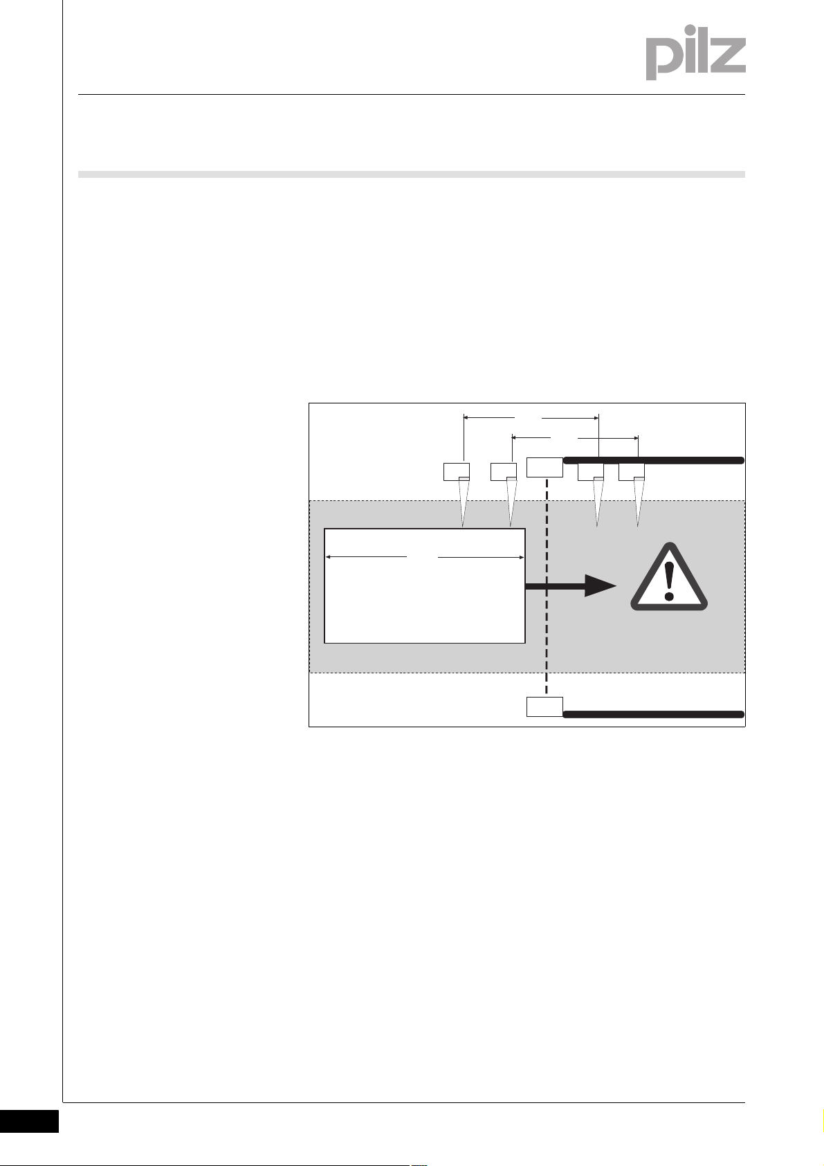
Position of the muting sensors2-Muting_Betriebsarten_sequenzielles Muting-Anordnung der Muting-Sensoren
The distance between the muting sensors MS1 and MS2 / MS3 and
MS4 should be as large as possible.
Vehicle length W must be greater than the distance between MS1 and
MS3 or MS2 and MS4 (W > A and W > B).
MS2 and MS3 must be positioned as close as possible in front of/be-
hind the AOPD.
2-8
Pilz GmbH & Co. KG, Felix-Wankel-Straße 2, 73760 Ostfildern, Germany
Telephone: +49 711 3409-0, Telefax: +49 711 3409-133, E-Mail: pilz.gmbh@pilz.de
Page 17

2Muting
2.4 Operating modes
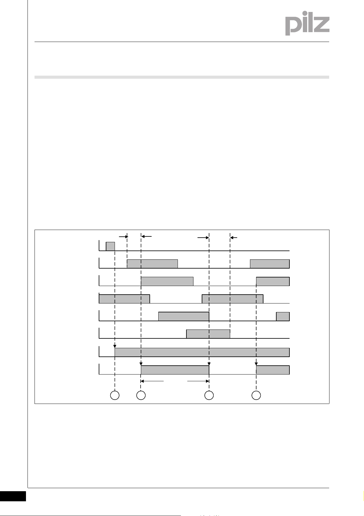
2.4.2.2 Switch conditions in sequential mode
Switch conditions in sequential mode2-Muting_Betriebsarten_sequenzielles Muting-Schaltbedingungen
Muting On
Entering the danger zone:
1. Muting sensors MS1 and MS2 must be operated consecutively (first
MS1, then MS2) within the configured simultaneity period. Muting is
activated by operating MS2.
2. Muting sensors MS3 and MS4 must be operated consecutively (first
MS3, then MS4) within the configured simultaneity period.
3. MS1 and MS2 must be cleared consecutively (first MS1, then MS2).
4. MS3 and MS4 must be cleared consecutively (first MS3, then MS4).
Leaving the danger zone:
1. Muting sensors MS4 and MS3 must be operated consecutively (first
MS4, then MS3) within the configured simultaneity period. Muting is
activated by operating MS3.
2. MS2 and MS1 must be operated consecutively (first MS2, then MS1).
3. MS4 and MS3 must be cleared consecutively (first MS4, then MS3).
4. MS2 and MS1 must be cleared consecutively (first MS2, then MS1).
Muting Off
Suspension of the safety function is cancelled as soon as the penultimate muting sensor, MS2 or MS3, is no longer operated, i.e. only
one muting sensor remains operated.
Pilz GmbH & Co. KG, Felix-Wankel-Straße 2, 73760 Ostfildern, Germany
Telephone: +49 711 3409-0, Telefax: +49 711 3409-133, E-Mail: pilz.gmbh@pilz.de
2-9
Page 18
2Muting
MS1
MS2
MS3 MS4
AOPD
W > C
A
B
C
2.4 Operating modes
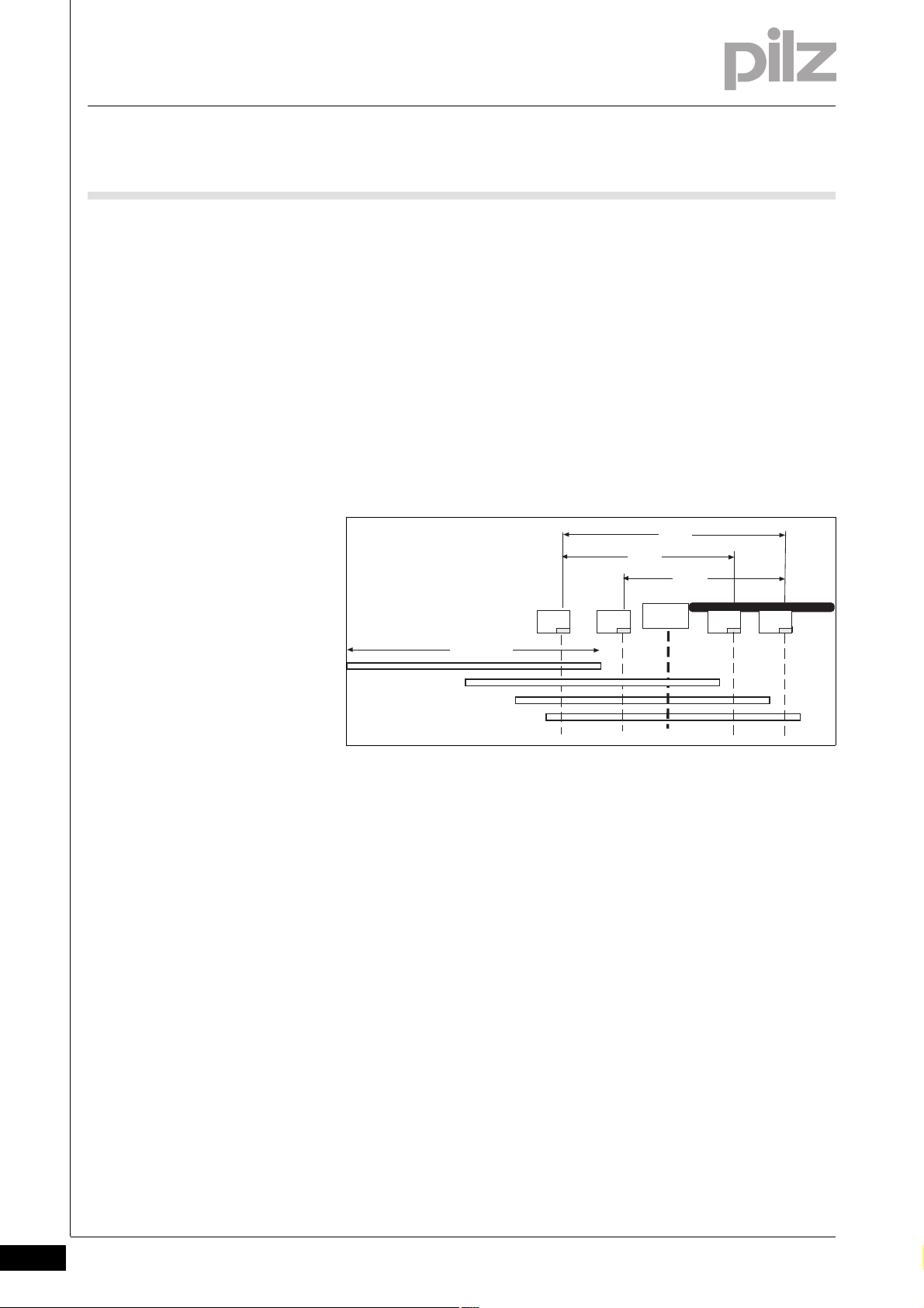
2.4.2.3 Sequence errors
Sequence errors2-Muting_Betriebsarten_sequenzielles Muting-Sequenzfehler
The muting sensors must be operated in a specific sequence in sequential mode. Once a particular directional movement has started (entry or
exit), it must be fully completed. Any deviation from the sequence shown
causes the enable output (enable = 0) and the output parameter
active
Vehicle length W greater than distance C between MS1 and MS4
All sensors are temporarily operated as the vehicle passes through. The
first muting sensor (MS1 upon entering, MS4 upon exiting) only becomes clear once all muting sensors have been operated.
Muting
to reset.
2-10
Pilz GmbH & Co. KG, Felix-Wankel-Straße 2, 73760 Ostfildern, Germany
Telephone: +49 711 3409-0, Telefax: +49 711 3409-133, E-Mail: pilz.gmbh@pilz.de
Page 19
2Muting
MS1
MS2
MS3 MS4
AOPD
W < C
A
B
C
2.4 Operating modes
Vehicle length W less than distance C between MS1 and MS4
As the vehicle passes through, the first muting sensor becomes clear
(MS1 upon entering, MS4 upon exiting) before the last muting sensor
has been operated.
MS1 MS2 MS3 MS4 Travel direction
0000
1000
1100
1110
1/0 1 1 1/0
0111
0011
0001
0000
Pilz GmbH & Co. KG, Felix-Wankel-Straße 2, 73760 Ostfildern, Germany
Telephone: +49 711 3409-0, Telefax: +49 711 3409-133, E-Mail: pilz.gmbh@pilz.de
2-11
Page 20
2Muting
1
0
1
Reset
1
0
1
0
1
0
1
0
1
0
32 4
MS1
MS2
Mut ing
Enabl e
AOPD
t
sync
t
sync
t
MUT
MS4
MS3
1
0
1
0
2.4 Operating modes
2.4.2.4 Diagnostic word
Diagnostic word2-Muting_Betriebsarten_Muting-Diagnosewort
Muting_Betriebsarten_Muting-Diagnosewort-bit10-para-sequ
2.4.2.5 Timing diagram (example)
Timing diagram (example)2-Muting_Betriebsarten_sequenzielles Muting-Zeitdiagramm
Messages can be queried in the PNOZmulti Configurator in bit mode
and linked further within the program.
Bit 1: Light curtain, interrupted (without active muting)
Bit 2: Waiting for reset (reset)
Bit 3: Sensor status unfeasible, override required
Bit 8: Muting time exceeded
Bit 9: Feasibility error, simultaneity period exceeded on muting sen-
Bit 10: Feasibility error, simultaneity period exceeded on muting sen-
sors 1 and 2, only one sensor operated
sors 3 and 4, only one sensor operated
Vehicle length W less than distance C between MS1 and MS4
Key:
t
= Simultaneity
sync
t
= Muting time
MUT
: Set enable with reset
: Start muting via MS1/MS2
: End muting by clearing MS3
: Restart muting via MS1/MS2
2-12
Pilz GmbH & Co. KG, Felix-Wankel-Straße 2, 73760 Ostfildern, Germany
Telephone: +49 711 3409-0, Telefax: +49 711 3409-133, E-Mail: pilz.gmbh@pilz.de
Page 21
2Muting
MS3
AOPD
AOPD
MS1
MS2
MS4
W
A
2.4 Operating modes
2.4.3 Parallel muting
Parallel muting2-
2.4.3.1 Position of the muting sensors
Position of the muting sensors2-Muting_Betriebsarten_paralleles Muting-Anordnung der Muting-Sensoren
Muting sensors MS1 and MS2/MS3 and MS4 must be positioned at
the same height to the left and right of the vehicle.
The vehicle length W must be greater than distance A between MS1
and MS3/MS2 and MS4.
The distance between the light curtain and the muting sensor must be
as short as possible.
Pilz GmbH & Co. KG, Felix-Wankel-Straße 2, 73760 Ostfildern, Germany
Telephone: +49 711 3409-0, Telefax: +49 711 3409-133, E-Mail: pilz.gmbh@pilz.de
2-13
Page 22

2Muting
2.4 Operating modes
2.4.3.2 Switch conditions in parallel mode
Switch conditions in parallel mode2-Muting_Betriebsarten_paralleles Muting-Schaltbedingungen
Muting On
Entering the danger zone:
1. Muting sensors MS1 and MS2 must be operated within the configured simultaneity period. Muting is activated.
2. Muting sensors MS3 and MS4 must be operated within the configured simultaneity period, before MS1 and MS2 are cleared.
Leaving the danger zone:
1. Muting sensors MS3 and MS4 must be operated within the configured simultaneity period. Muting is activated.
2.4.3.3 Diagnostic word
Diagnostic word2-Muting_Betriebsarten_Muting-Diagnosewort
Muting_Betriebsarten_Muting-Diagnosewort-bit10-para-sequ
2. Muting sensors MS1 and MS2 must be operated before MS3 and
MS4 are cleared.
Muting Off
Suspension of the safety function is cancelled as soon as the penultimate muting sensor, MS3/MS4 upon entering or MS1/MS2 upon exiting,
is no longer operated. In other words, only one muting sensor remains
operated.
Messages can be queried in the PNOZmulti Configurator in bit mode
and linked further within the program.
Bit 1: Light curtain, interrupted (without active muting)
Bit 2: Waiting for reset (reset)
Bit 3: Sensor status unfeasible, override required
Bit 8: Muting time exceeded
Bit 9: Feasibility error, simultaneity period exceeded on muting sen-
sors 1 and 2, only one sensor operated
Bit 10: Feasibility error, simultaneity period exceeded on muting sen-
sors 3 and 4, only one sensor operated
2-14
Pilz GmbH & Co. KG, Felix-Wankel-Straße 2, 73760 Ostfildern, Germany
Telephone: +49 711 3409-0, Telefax: +49 711 3409-133, E-Mail: pilz.gmbh@pilz.de
Page 23

2Muting
1
0
1
Reset
1
0
1
0
1
0
1
0
1
0
32 4
MS1
MS2
Muting
Enable
AOPD
t
sync
t
sync
t
MUT
MS4
MS3
1
0
1
0
2.4 Operating modes
2.4.3.4 Timing diagram (example)
Timing diagram (example)2-_Dummy-Vorlage
Key:
t
= Simultaneity
sync
= Muting time
t
MUT
: Set enable with reset
: Start muting via MS1/MS2
: End muting by clearing MS3 or MS4
: Restart muting via MS1/MS2
Pilz GmbH & Co. KG, Felix-Wankel-Straße 2, 73760 Ostfildern, Germany
Telephone: +49 711 3409-0, Telefax: +49 711 3409-133, E-Mail: pilz.gmbh@pilz.de
2-15
Page 24

2Muting
AOPD
AOPD
MS1
MS2
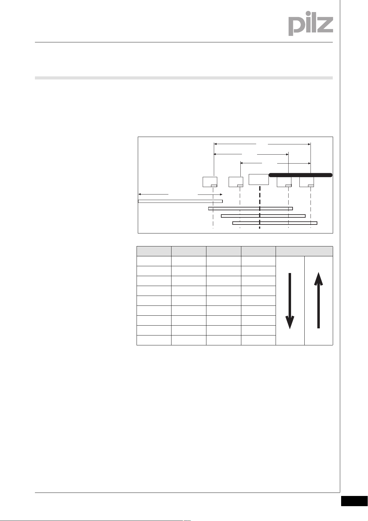
2.4 Operating modes
2.4.4 Cross muting
Cross muting2-
2.4.4.1 Position of the muting sensors
Position of the muting sensors2-Muting_Betriebsarten_Kreuz- Muting-Anordnung der Muting-Sensoren
Muting sensors may be reflective or send/receive light beam devices,
for example. The beams must always intersect within the danger
zone.
The muting sensors must be positioned in such a way that the light
curtain is interrupted before the beam intersection can be reached
from outside the danger zone.
Muting sensors MS3 and MS4 are not used.
2-16
WARNING!
Loss of safety function due to incorrect position of muting
sensors
Depending on the application, serious injury or death may result.
Ensure that you comply with the installation dimensions shown
in the figure overleaf.
Pilz GmbH & Co. KG, Felix-Wankel-Straße 2, 73760 Ostfildern, Germany
Telephone: +49 711 3409-0, Telefax: +49 711 3409-133, E-Mail: pilz.gmbh@pilz.de
Page 25

2Muting
max. 20 ... 30 cm
min. 20 cm
Muting sensor
Muting sensor
Muting sensor
Danger zone
Intersection of
muting sensor beams
Light curtain
Access guarding
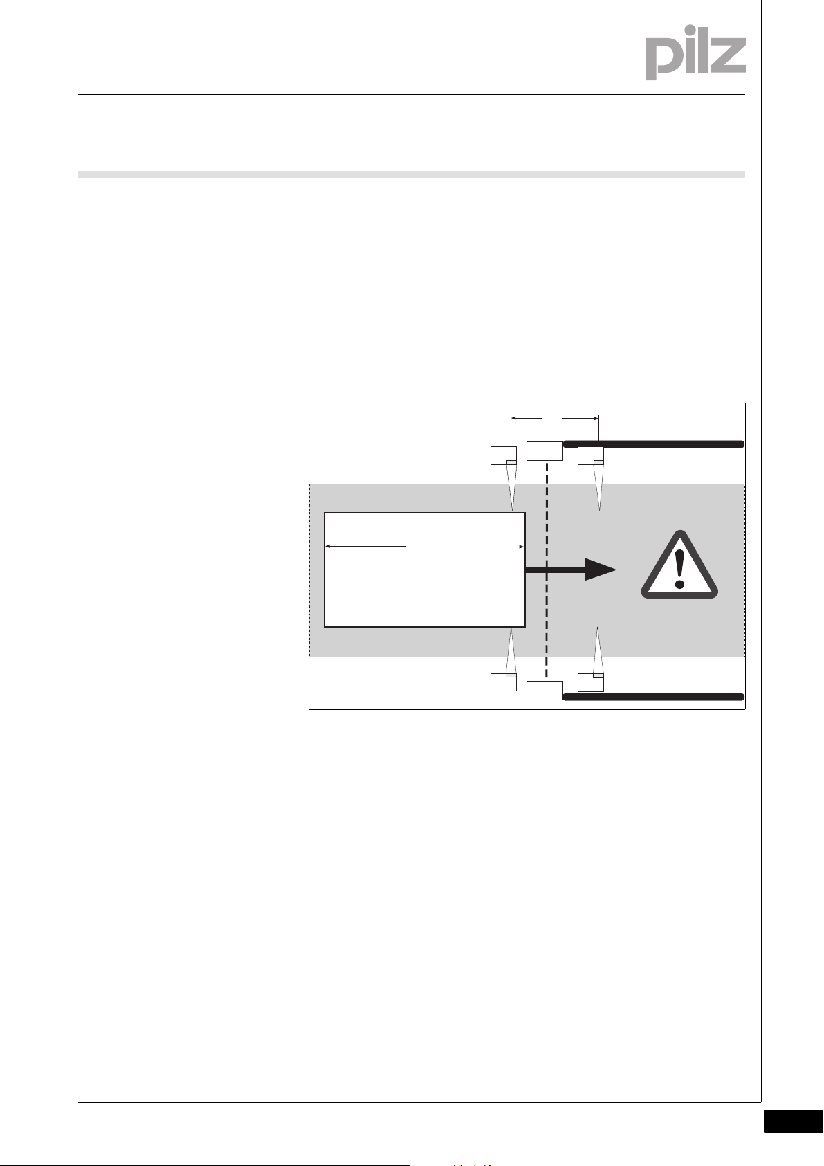
2.4 Operating modes
Fig. 2-1: Position of the muting sensors (side view and plan view)
Pilz GmbH & Co. KG, Felix-Wankel-Straße 2, 73760 Ostfildern, Germany
Telephone: +49 711 3409-0, Telefax: +49 711 3409-133, E-Mail: pilz.gmbh@pilz.de
2-17
Page 26

2Muting
2.4 Operating modes
2.4.4.2 Switch conditions in cross mode
Switch conditions in cross mode2-Muting_Betriebsarten_Kreuz-Muting-Schaltbedingungen
Muting On
Muting sensors MS1 and MS2 must be operated within the configured
simultaneity period.
Muting Off
The suspension of the safety function is lifted when one muting sensor
at most is still operated.
2.4.4.3 Diagnostic word
Diagnostic word2-Muting_Betriebsarten_Muting-Diagnosewort
Messages can be queried in the PNOZmulti Configurator in bit mode
and linked further within the program.
Bit 1: Light curtain, interrupted (without active muting)
Bit 2: Waiting for reset (reset)
Bit 3: Sensor status unfeasible, override required
Bit 8: Muting time exceeded
Bit 9: Feasibility error, simultaneity period exceeded on muting sen-
sors 1 and 2, only one sensor operated
2-18
Pilz GmbH & Co. KG, Felix-Wankel-Straße 2, 73760 Ostfildern, Germany
Telephone: +49 711 3409-0, Telefax: +49 711 3409-133, E-Mail: pilz.gmbh@pilz.de
Page 27

2Muting
1
0
1
Reset
1
0
1
0
1
0
1
0
1
0
32
4
MS1
MS2
Mut i ng
Ena bl e
AOPD
t
sync
t
sync
t
MUT
2.4 Operating modes
2.4.4.4 Timing diagram (example)
Timing diagram (example)2-_Dummy-Vorlage
Key:
t
= Simultaneity
sync
= Muting time
t
MUT
: Set enable with reset
: Start muting via MS1/MS2
: End muting by clearing MS1 or MS2
: Restart muting via MS1/MS2
Pilz GmbH & Co. KG, Felix-Wankel-Straße 2, 73760 Ostfildern, Germany
Telephone: +49 711 3409-0, Telefax: +49 711 3409-133, E-Mail: pilz.gmbh@pilz.de
2-19
Page 28

3 Safety Mat/Safe Edge
3.1 Introduction
33000Safety Mat/Safe EdgeSafety Mat/Safe Edge3-3.1Introduction3100In troduction3-Schaltmatte_Einführung
This chapter describes the use of pressure-sensitive protective devices
(safety mats and safe edges) with the PNOZmulti.
Please refer to the following:
The operating manuals provided with the PNOZmulti units
The PNOZmulti technical catalogue
The certificate showing approved pressure-sensitive protective de-
vices
The installation manual and user information provided by the safety
Schaltmatte_Definition
mat/safe edge manufacturer (see "Intended use").
Safety mat
A safety mat is a protective device which detects a person standing on
it or stepping on to it. The safety mat comprises a sensor which responds to the application of pressure, a control unit and an output signal
switching device.
With a safety mat, the effective sensing area is deformed locally when
the sensor is operated.
Safe edge
A safe edge is a protective device which is designed to detect contact
from a person or any part of a person's body. It comprises:
A sensor, which generates a signal when pressure is applied to part
of its surface, whereby:
– Its length is greater than its width
– Its cross section is constant across its length
– Cross-sectional width is greater than 8 mm
– The effective sensing area is deformed locally to actuate the sensor
A control unit that responds to a signal from the sensor and generates
an output signal that it sends to the machine control system.
Pilz GmbH & Co. KG, Felix-Wankel-Straße 2, 73760 Ostfildern, Germany
Telephone: +49 711 3409-0, Telefax: +49 711 3409-133, E-Mail: pilz.gmbh@pilz.de
3-1
Page 29

3 Safety Mat/Safe Edge
3.2 Safety
3.2Safety3200Safety3-
3.2.1 Intended use
Intended use3-Schaltmatte_Sicherheit_ Bestimmungsgemäße Ver wendung
Base units from the configurable control system PNOZmulti and PNOZmulti Mini plus the expansion module PNOZ mi1p are suitable for connecting pressure-sensitive protective devices.
The units may only be used as a safety system in conjunction with the
approved pressure-sensitive protective devices (see certificate showing approved pressure-sensitive protective devices).
The pressure-sensitive protective devices must be connected to the
inputs on the PNOZmulti units via the PSEN im1 interface or type
1N4007 diodes (see "Commissioning the safety system").
Only pressure-sensitive protective devices without installed terminat-
ing resistors are suitable.
The following are not permitted: Walking aids such as canes and
wheeled vehicles
The configurable control system PNOZmulti is used as a control unit
and as an output signal switching device in accordance with
EN 1760-1, 09/97.
3.2.2 Safety guidelines
Safety guidelines3-Schaltmatte_Sicherheit_ Sicherheitshinwe ise
CAUTION!
When pressure-sensitive protective devices are connected to
PNOZmulti units, the units (including the coated version) may
only be operated at an ambient temperature of 0 to +60 °C.
Do not install and commission the safety system until you have read and
understood this chapter, the technical catalogue and the installation
manual from the safety mat/safe edge manufacturer.
You must also be familiar with the applicable regulations for health and
safety at work and accident prevention.
In particular you should refer to EN 1760-1 and EN 1760-2.
In terms of faults the safety system complies with Category 3, PL d of
EN ISO 1349-1 and SIL CL 2 of EN IEC 62061. With the safety mat
it's important to consider Note 3 to Clause 4.15 of EN 1760-1
The categories for safety mats on machines in accordance with EN
13849-1 are specified in type C standards.
3-2
Pilz GmbH & Co. KG, Felix-Wankel-Straße 2, 73760 Ostfildern, Germany
Telephone: +49 711 3409-0, Telefax: +49 711 3409-133, E-Mail: pilz.gmbh@pilz.de
Page 30

3 Safety Mat/Safe Edge
3.3 Function description
3.3Function description3300Function description3-Schaltmatt e_Funktionsbesch reibung
The pressure-sensitive safety device is supplied with PNOZmulti test
pulse outputs. The test pulses are evaluated by PNOZmulti inputs (see
section titled "Commissioning the safety system"). Short across contacts and open circuits are detected.
Pilz GmbH & Co. KG, Felix-Wankel-Straße 2, 73760 Ostfildern, Germany
Telephone: +49 711 3409-0, Telefax: +49 711 3409-133, E-Mail: pilz.gmbh@pilz.de
3-3
Page 31

3 Safety Mat/Safe Edge
3.4 Configuration in the PNOZmulti Configurator
3.4Configuration in the PNOZ multi Configurator3400Configurat ion in the PNOZmulti C onfigurator3-Schaltmatte_Konfiguration
Operating modes
– Automatic reset (start):
After the pressure-sensitive protective device has been activated,
the output immediately returns to "1" once the pressure-sensitive
protective device is cleared.
– Manual reset (start):
The output does not return to "1" until the reset button has been
pressed. This eliminates the possibility of the reset button being
overridden, triggering automatic activation. A reset is only possible
if the pressure-sensitive protective device is not activated.
Start-up test
The start-up test prevents an automatic restart after a power failure
and subsequent return of voltage. The unit checks whether the nonactivated pressure-sensitive protective device was activated and
cleared after supply voltage was applied.
The output of the pressure-sensitive protective device function ele-
ment is "1" if the pressure-sensitive protective device has not been
activated. This safety function must be retained when this signal is
linked further within the PNOZmulti Configurator:
– Semiconductor outputs: High signal
– Relay outputs: Safety contacts closed
3.4.1 Allocation of test pulses to inputs
Allocation of test pulses to inputs3-Schaltmatte_Konfiguration- Zuordnung zu den Eing ängen
The test pulses can only be connected to the inputs as follows:
Input 1: Test pulse T0
Input 2: Test pulse T1
or
Input 1: Test pulse T2
Input 2: Test pulse T3
INFORMATION
Test pulses that you use for the pressure-sensitive protective
device cannot be reused for test pulses in conjunction with other
safety devices.
3-4
Pilz GmbH & Co. KG, Felix-Wankel-Straße 2, 73760 Ostfildern, Germany
Telephone: +49 711 3409-0, Telefax: +49 711 3409-133, E-Mail: pilz.gmbh@pilz.de
Page 32

3 Safety Mat/Safe Edge
3.5 Commissioning the safety system
3.5Commissioning the safety system3500Commissioning the safety system3-Schaltmatt e_Sicherheitssyste m in Betrieb nehmen- einleitung
When using the pressure-sensitive protective device, please note the
following:
The following are not permitted: Walking aids such as canes and
wheeled vehicles
3.5.1 Preparing for commissioning
Preparing for commissioning3-Schaltmatte_Sicherheits system in Betrieb ne hmen-vorbereiten
Please note the following when preparing for commissioning:
Cables that have to be laid outside the control cabinet must be pro-
tected from mechanical damage, e.g. by installing them in a conduit.
Pressure-sensitive protective devices may not be fitted with a termi-
nating resistor.
The configured test pulse outputs should be used exclusively for test
pulses on the pressure-sensitive protective devices. Be sure to note
the information provided in "Technical details".
Pilz GmbH & Co. KG, Felix-Wankel-Straße 2, 73760 Ostfildern, Germany
Telephone: +49 711 3409-0, Telefax: +49 711 3409-133, E-Mail: pilz.gmbh@pilz.de
3-5
Page 33

3 Safety Mat/Safe Edge
T0/T2
T1/T3
I0
I1
PNOZmulti
PSEN im1
1.2
1.1
5.2
5.1
2
1
...
T0/T2
T1/T3
I1
I0
I3
I2
PSEN im1
1.2
1.1
5.2
5.1
2
1
PNOZmulti
1 ... max. 5
...
...
...
3.5 Commissioning the safety system
3.5.2 Preparing for operation
Preparing for operation3-Schaltmatte_Sicherheitssystem in Betrieb nehmen-betriebsbereitschaft herstellen
Input circuit
Connecting one pressure-sensitive protective device,
max. area of pressure-sensitive protective device = 8 m
Connect the pressure-sensitive protective device to the test pulse
outputs and the inputs (in examples I0 to I3).
Please note:
Always connect the pressure-sensitive protective devices to the
PNOZmulti units via
– interface PSEN im1,
– diodes of type 1 N4003 ...1N4007,
– or via the terminal block with filter, order no. 774 195, 774 196.
0 V may not be connected to the terminal block!
2
3-6
Connecting multiple pressure-sensitive protective devices,
permitted per dual-pole input: max. 5 pressure-sensitive
protective devices in series, max. area of pressure-sensitive protective device = 8 m
Pilz GmbH & Co. KG, Felix-Wankel-Straße 2, 73760 Ostfildern, Germany
Telephone: +49 711 3409-0, Telefax: +49 711 3409-133, E-Mail: pilz.gmbh@pilz.de
2
Page 34

3 Safety Mat/Safe Edge
I5
S3
24 V DC
3.5 Commissioning the safety system
Set the reset features through wiring of the reset circuit (in example
I5). Only effective if
PNOZmulti Configurator.
Manual reset
manual reset
is configured in the
Pilz GmbH & Co. KG, Felix-Wankel-Straße 2, 73760 Ostfildern, Germany
Telephone: +49 711 3409-0, Telefax: +49 711 3409-133, E-Mail: pilz.gmbh@pilz.de
3-7
Page 35

3 Safety Mat/Safe Edge
3.6 Operation
3.6Operation3600Operation3-_Dummy-Vorlage
The safety system can only be started if the pressure-sensitive protective device has not been activated. The unit detects the operating mode
set on start-up.
3.6.1 Diagnostic word
Diagnostic word3-Schaltmatte-Diagnosewort
Messages can be queried in the PNOZmulti Configurator in bit mode
and linked further within the program.
Bit 0: Pressure-sensitive protective device clear, enable issued
Bit 2: Pressure-sensitive protective device activated
Bit 3: Waiting for reset
Bit 4: Waiting for start-up test
Bit 6: Open circuit detected, signal error
3-8
Pilz GmbH & Co. KG, Felix-Wankel-Straße 2, 73760 Ostfildern, Germany
Telephone: +49 711 3409-0, Telefax: +49 711 3409-133, E-Mail: pilz.gmbh@pilz.de
Page 36

3 Safety Mat/Safe Edge
3.7 Technical Details
3.7Technical Details3700Technical Details3-Technische Daten
Technical details
Reaction time (from activation of the pressure-sensitive protective device until an instantaneous safety output drops out)*
Max. area of pressure-sensitive protective devices per dual-pole input 8 m
Max. number of pressure-sensitive protective devices connected in se-
ries per dual-pole input
Min. cross section of external conductor 0.5 mm
Max. cable length, PNOZmulti - pressure-sensitive protective device 100 m
Max. resistance of safety mat/safe edge 150 Ohm
*The stated reaction time is the maximum value for pressure-sensitive
protective devices. For details of the specific reaction time in conjunction with the respective approved safety mat or safe edge, please refer
to the certificate showing approved pressure-sensitive protective devices.
< 200 ms
2
5
2
Pilz GmbH & Co. KG, Felix-Wankel-Straße 2, 73760 Ostfildern, Germany
Telephone: +49 711 3409-0, Telefax: +49 711 3409-133, E-Mail: pilz.gmbh@pilz.de
3-9
Page 37

3 Safety Mat/Safe Edge
3-10
Pilz GmbH & Co. KG, Felix-Wankel-Straße 2, 73760 Ostfildern, Germany
Telephone: +49 711 3409-0, Telefax: +49 711 3409-133, E-Mail: pilz.gmbh@pilz.de
Page 38

4Burners
4.1 Introduction
44000BurnersBurners4-4.1Intro duction4100Introduc tion4-Einführung
This chapter describes how to control and monitor burners with the base
units PNOZ m3p from the configurable control system PNOZmulti.
Control and monitoring of a burner is configured in the PNOZmulti Configurator using the burner element.
When using the burner element please also refer to:
The operating manuals provided with the PNOZmulti units
The online help for the PNOZmulti Configurator.
Pilz GmbH & Co. KG, Felix-Wankel-Straße 2, 73760 Ostfildern, Germany
Telephone: +49 711 3409-0, Telefax: +49 711 3409-133, E-Mail: pilz.gmbh@pilz.de
4-1
Page 39

4Burners
4.2 Safety
4.2Safety4200Safety4-
4.2.1 Intended use
Intended use4-Gertebeschreibung
The burner logic element can only be used in conjunction with the base
unit PNOZ m3p.
The burner logic element in the PNOZmulti Configurator is designed to
control and monitor burners in accordance with the standards:
EN 298: Automatic gas burner control systems for gas burners and
gas burning appliances with or without fans
EN 12953-7: Shell boilers
EN 12952-8: Water-tube boilers and auxiliary installations
EN 50156-1: Electrical equipment for furnaces
EN 61508: SIL 3: Functional safety of safety-related electrical/elec-
tronic/programmable electronic systems
EN 230: Automatic burner control systems for oil burners
EN 267: Automatic forced draught burners for liquid fuels (draft)
EN 298: Automatic gas burner control systems for gas burners and
gas burning appliances with or without fans
EN 676: Automatic forced draught burners for gaseous fuels
EN 746-2: Industrial thermoprocessing equipment
EN 1643: Valve proving systems for automatic shut-off valves for gas
burners and gas appliances
The relay output module PNOZ mo5p has diverse relay outputs and is
therefore suitable for activating safety valves on a burner in accordance
with EN 50156.
4-2
Pilz GmbH & Co. KG, Felix-Wankel-Straße 2, 73760 Ostfildern, Germany
Telephone: +49 711 3409-0, Telefax: +49 711 3409-133, E-Mail: pilz.gmbh@pilz.de
Page 40

4Burners
4.3 Configuration in the PNOZmulti Configurator
4.3Configuration in the PNOZ multi Configurator4300Configurat ion in the PNOZmulti C onfigurator4-
4.3.1 Functions
Functions4-_Dummy-Vorlage
The burner logic element contains all the functions needed to control
and monitor burners.
These include
monitoring of
Safety chains
Combustion air pressure
Ignition
Flame monitoring
External compound controller
Tightness control
and control of:
Safety valves
Ignition valves
Vent valve
Ignition
External compound controller
Combustion air blower
The following oil and gas burner types can be controlled and monitored:
Master burner with direct ignition
Master burner with indirect ignition and joint flame monitoring
Master burner with indirect ignition and separate flame monitoring
Slave burner with direct ignition
Slave burner with indirect ignition and joint flame monitoring
Slave burner with indirect ignition and separate flame monitoring
The required burner type and necessary monitoring and control functions can be set in the PNOZmulti Configurator (see Monitoring functions/settings for the burner cycle). This will influence the burner cycle.
A burner cycle has several phases (steps). The configuration determines
which steps are carried out (see Burner cycle).
Provided the input signals match the set values within a step, the program cycle will be continued. The system will pass to the next step as
soon as the configured step time has elapsed.
If the input signals do not match the set values within a step, an error will
be detected. This will lead either to a fault lockout or a safety shutdown,
depending on the input signal and configuration.
Pilz GmbH & Co. KG, Felix-Wankel-Straße 2, 73760 Ostfildern, Germany
Telephone: +49 711 3409-0, Telefax: +49 711 3409-133, E-Mail: pilz.gmbh@pilz.de
4-3
Page 41

4Burners
4.3 Configuration in the PNOZmulti Configurator
4.3.2 Monitoring functions/settings for the burner cycle
Monitoring functions/se ttings for the bur ner cycle4-
4.3.2.1 Combustion air pressure monitoring, activating the combustion air blower, compound con-
Combustion air pressure monitoring, activating the combustion air blower, compound controller monitoring4-Funktionsbeschreibung_Ueberwachungen_Brennertyp
troller monitoring
You can set whether the activated burner is a master burner or a slave
burner.
Master burners
Master burners have their own combustion air supply, which is controlled and monitored directly. The following monitoring/control functions are performed on master burners:
– The combustion air pressure is monitored. For this, the "AirP" input
must be linked to the device that monitors the required air amount
(generally an air pressure monitor).
– The combustion air blower is activated via the "BLOW" output.
– The compound controller can be activated and monitored. This is
necessary when an electronic compound controller is present (see
section below, entitled "Compound controller").
Slave burners
Slave burners do not have their own combustion air supply. As a result, no monitoring takes place. This burner type is used for multiburners, for example, which are fitted with a central combustion air
supply and a monitoring function.
WARNING!
Loss of safety function due to incorrect use of the
ner
type
If the
Slave burner
type is used to avoid pre-purge and a com-
Slave bur-
bustion air supply is not guaranteed, serious injury or death may
result, depending on the application.
Only use the slave burner type if the combustion air supply is
guaranteed elsewhere.
Please also note the following with the
The "AirP" input must be connected to a signal indicating the pres-
Slave burner
type:
ence of a central combustion air supply that is functioning correctly.
There is no check to ensure that this input is at rest position when the
burner is switched off.
The burner cannot be started (signal at the "Start" input) until it is
guaranteed that there is no flammable mixture within the combustion
chamber or associated areas or within the exhaust system.
4-4
Pilz GmbH & Co. KG, Felix-Wankel-Straße 2, 73760 Ostfildern, Germany
Telephone: +49 711 3409-0, Telefax: +49 711 3409-133, E-Mail: pilz.gmbh@pilz.de
Page 42

4Burners
Safety valve 1
Safety valve 2
Ignition valve
4.3 Configuration in the PNOZmulti Configurator
4.3.2.2 Ignition
Ignition4-Funktionsbeschreibung_Ueberwachungen_Zuendung
The ignition transformer is activated via the "IGNT" output.
You can select two types of ignition in the PNOZmulti Configurator:
Direct ignition
With direct ignition, no separate ignition burner is present. The main
burner is ignited directly via the ignition transformer.
Indirect ignition
With indirect ignition, a separate ignition burner is present. The main
burner is ignited by an ignition flame, which is ignited via an ignition
transformer. Fuel may not be supplied to the main burner until the ignition burner has been ignited and the ignition flame is stable.
The ignition valve is activated via the IV output.
The following setting options are available for the behaviour of the ignition flame:
– Ignition valve is closed after ignition,
i.e. the ignition flame is to be extinguished once the main burner is
successfully ignited, or
– (only possible when separate flame monitoring is configured (see
section entitled "Flame monitoring")): Ignition valve remains open
after ignition,
i.e. the ignition flame is to stay lit once the main burner is success-
fully ignited.
The ignition valve must be positioned as follows:
Pilz GmbH & Co. KG, Felix-Wankel-Straße 2, 73760 Ostfildern, Germany
Telephone: +49 711 3409-0, Telefax: +49 711 3409-133, E-Mail: pilz.gmbh@pilz.de
4-5
Page 43

4Burners
4.3 Configuration in the PNOZmulti Configurator
4.3.2.3 Flame monitoring
Flame monitoring4-Funktionsbeschreibung_Ueberwachungen_Flammenueberwachung
Flame monitoring is used to establish and signal the presence of a flame.
To ensure that the signal is actually a result of the flame and not of some
external light source, the absence of the flame is monitored during a
burner cycle (e.g. during pre-purge). With direct ignition, the main flame
is monitored.
With indirect ignition you can select between two types of flame monitoring:
Joint flame monitoring
Ignition flame and main flame are monitored jointly. The FLAM input
for the main flame must be logically linked to flame monitoring. The
FLAI input for the ignition flame will not then be evaluated.
Separate flame monitoring
Ignition flame and main flame are monitored separately; each have
their own flame monitoring device.
4.3.2.4 Compound controller
Compound controller4-Funktionsbeschreibung_Ueberwachungen_Verb undregelung
If master burners have an external electronic compound controller, the
compound controller must be activated and monitored via the burner element
The compound controller controls and monitors the fuel/air ratio. The
regulating devices for the amount of combustion air and fuel are activated for this purpose.
The "PURG" output is activated during the step: "Compound control-
ler to pre-purge position". This output signal is intended to switch the
compound controller to the pre-purge position (maximum amount of
combustion air).
During the steps "Pre-purge ...", a signal is expected at the "PUR" in-
put from the compound controller, indicating that the compound controller is in "pre-purge" position. This signal must not occur until the
airflow rate required for pre-purge is present.
The "IGNI" output is activated during the step: "Compound controller
to ignition position". This output signal is intended to switch the compound controller to the ignition position (optimum fuel/air ratio for ignition).
During the steps "Ignition ...", a signal is expected at the "IGN" input
from the compound controller, indicating that the compound controller is in "ignition" position. This signal must not occur until the optimum fuel/air ratio for ignition is present.
4-6
Pilz GmbH & Co. KG, Felix-Wankel-Straße 2, 73760 Ostfildern, Germany
Telephone: +49 711 3409-0, Telefax: +49 711 3409-133, E-Mail: pilz.gmbh@pilz.de
Page 44

4Burners
Safety valve 1
Safety valve 2
Vent valve
4.3 Configuration in the PNOZmulti Configurator
4.3.2.5 Tightness control
Tightness control4-Funktionsbeschreibung_Ueberwachungen_Dichtheitskontrolle
You can select whether to carry out tightness control. With tightness
control, the section between the two safety valves will first be vented,
then refilled and the pressure measured. The pressure is monitored at
the "GP" input.
The plant must undergo a hazard analysis to determine whether tightness control is necessary. The hazard analysis should also determine
whether venting is permitted via safety valve 2.
The following configuration options are available:
Vent via the vent valve (the vent valve is activated via the VV output)
The vent valve must be positioned as follows:
or
Vent via safety valve 2
Continuous vent (in which case, tightness control is not carried out)
No tightness control and no continuous vent
It's also possible to configure when tightness control is to be carried out:
Tightness control prior to ignition
Tightness control after the burner has shut down. (Even with this set-
ting, tightness control will be carried out prior to ignition if the previous burner cycle was interrupted due to an error.)
Pilz GmbH & Co. KG, Felix-Wankel-Straße 2, 73760 Ostfildern, Germany
Telephone: +49 711 3409-0, Telefax: +49 711 3409-133, E-Mail: pilz.gmbh@pilz.de
4-7
Page 45

4Burners
4.3 Configuration in the PNOZmulti Configurator
4.3.2.6 High temperature
High temperature4-Funktionsbeschreibung_Ueberwachungen_Hochtemperatur
"High temperature" mode can be activated via the "HTmp" input if the
conditions for high temperature in high temperature plants have been
met in accordance with EN 746-2 and the fuel in the combustion chamber self-ignites safely.
As the fuel in the combustion chamber self-ignites in high temperature
mode, the burner cycle will change.
The following steps are no longer performed in high temperature mode:
Any steps in connection with pre-purge and post-purge
Tightness control
Pre-ignition
Afterburn
Flame monitoring is also deactivated; the outputs for activating "Compound controller for pre-purge position" (PURG) and the ignition transformer (IGNT) are no longer activated.
WARNING!
Potential loss of safety functions in "High temperature"
mode!
If the conditions for high temperature in accordance with EN
746-2 are not met, safety-related steps in "High temperature"
mode will no longer be carried out. Depending on the application, serious injury or death may result.
Make sure that "High temperature" mode is only active when the
conditions for high temperature in accordance with EN 746-2
are met.
In any of the steps within the cycle, the "HTmp" input can be used to
switch between high temperature mode and normal mode (see also section entitled "Inputs and outputs").
4-8
Pilz GmbH & Co. KG, Felix-Wankel-Straße 2, 73760 Ostfildern, Germany
Telephone: +49 711 3409-0, Telefax: +49 711 3409-133, E-Mail: pilz.gmbh@pilz.de
Page 46

4Burners
4.3 Configuration in the PNOZmulti Configurator
4.3.2.7 Plant-dependent monitoring functions
Plant-dependent monitori ng functions4-Funktionsbeschreibung_Ueberwachungen_Sicherheitsketten
Plant-dependent monitoring functions, which are intended to trigger a
burner shutdown where necessary (e.g. when the temperature is too
high), must be incorporated into the safety sequences. In other words,
they must be linked to inputs CHA1, CHA2 or CHAi.
Monitoring functions which are intended to be active from burner startup to burner shutdown must be linked to either CHA1 or CHA2.
Monitoring functions which are only intended to be active during ignition
and burner operation must be linked to CHAi (see also section entitled
"Inputs and outputs").
4.3.2.8 Shutdown types
Shutdown types4-Funktionsbeschreibung_Ueberwachungen_Abschaltungsarten
A controlled shutdown can be performed via the "Stop" input (e.g. if energy is no longer required). The burner is then brought to a stop.
WARNING!
Loss of safety function due to incorrect use of the "Stop" input!
If the "Stop" input is used to reproduce a safety shutdown or
fault lockout, serious injury or death may result, depending on
the application.
Only use the "Stop" input for a controlled shutdown.
An error is detected if the input signals within a step do not match the
values set for the monitoring operation. This will lead either to a fault
lockout or a safety shutdown, depending on the input signal and configuration. With both shutdown types, all outputs on the burner element are
shut down immediately and the sequence program is aborted.
Safety shutdown
After a safety shutdown, the burner cycle is automatically restarted
after a configurable period, if there is no error present.
Fault lockout
With a fault lockout, if there is no error present, it is necessary to reset
and then manually restart to enable a new burner cycle.
Pilz GmbH & Co. KG, Felix-Wankel-Straße 2, 73760 Ostfildern, Germany
Telephone: +49 711 3409-0, Telefax: +49 711 3409-133, E-Mail: pilz.gmbh@pilz.de
4-9
Page 47

4Burners
4.3 Configuration in the PNOZmulti Configurator
For the following steps you can select which shutdown type will occur
in the event of an error in the PNOZmulti Configurator:
Safety chain 1 broken (input CHA1)
Safety chain 2 broken (input CHA2)
Ignition and operation safety chain broken (input CHAi)
No air pressure during operation (during start-up: fault lockout)
Faulty flame signal during operation (during start-up: fault lockout)
Please note:
The plant must undergo a hazard analysis to determine whether a safety
shutdown is permitted for an error.
4.3.2.9 Step times
Step times4-Funktionsbeschreibung_Ueberwachungen_Schrittzeiten
You can set a time for most of the steps within a cycle (see View burner
cycle, define step times). The time determines how long the step will be
active. While the step is active, the inputs must conform to the pre-defined set values. Once this time has elapsed, the next step will be started
(see also Burner cycle).
When configuring the step times, please note the following with the
steps below:
Steps 5 - 9 "Pre-purge...)
The total duration of steps 5 - 9 for pre-purge must not be less than
the minimum duration for pre-purge calculated via the plant's hazard
analysis.
Step 13 "Ignite ignition flame / 1st safety time"
The configured step time must not be longer than the 1st safety time.
The maximum duration of the 1st safety time is calculated based on
a hazard analysis of the plant.
Step 15 "Ignite ignition flame / 2nd safety time"
The configured step time must not be longer than the 2nd safety
time. The maximum duration of the 2nd safety time is calculated
based on a hazard analysis of the plant.
4-10
A step time cannot be set for the following steps: "Burner switched off",
"Check start conditions" and "Burner in operation/control enable".
Pilz GmbH & Co. KG, Felix-Wankel-Straße 2, 73760 Ostfildern, Germany
Telephone: +49 711 3409-0, Telefax: +49 711 3409-133, E-Mail: pilz.gmbh@pilz.de
Page 48

4Burners
4.4 Burner cycle
4.4Burner cycle44 00Burner cycle4-
4.4.1 Steps
Steps4-Funktionsbeschreibung_Schritte
Each step has a fixed step identifier (0 ... 31).
The steps are performed consecutively within the burner cycle (step 1
first, then step 2).
Some steps are only important internally and are not displayed (e.g. step
4). That's why some numbers from 0 to 31 are not listed as steps.
The length of the steps depends on the configuration and the burner cycle. There are steps for which you can set a step time in the PNOZmulti
Configurator; others have a fixed step time, or the step time depends on
the burner cycle.
A step time cannot be set for the following steps. They are run in each
burner cycle, irrespective of the configuration.
Step 0: Burner switched off
Step 1: Check start conditions
Step 18: Burner in operation/controller enable
A step time can be set for the following steps. Your configuration will determine which of these steps are performed in your burner cycle.
Step 2: Start-up combustion air blower
Step 3: Compound controller to pre-purge position
Step 5: Pre-purge/tightness control: Vent
Step 6: Pre-purge/tightness control: Test air pressure
Step 7: Prepurge/tightness control, filling:
Step 8: Prepurge/tightness control, test fuel pressure
Step 9: Continue pre-purge
Step 10: Compound controller to ignition position
Step 12: Pre-ignition
Step 13: Ignite ignition flame/1st safety time
Step 14: Stabilise ignition flame
Step 15: Ignite main flame/2nd safety time
Step 16: Stabilise main flame
Step 17: Burner in operation/start position
Step 20: Afterburn
Step 21: Post-purge
Step 22: Run down combustion air blower
Step 24: Tightness control, vent
Step 25: Tightness control, test air pressure
Step 26: Tightness control, filling
Step 27: Tightness control, test fuel pressure
Pilz GmbH & Co. KG, Felix-Wankel-Straße 2, 73760 Ostfildern, Germany
Telephone: +49 711 3409-0, Telefax: +49 711 3409-133, E-Mail: pilz.gmbh@pilz.de
4-11
Page 49

4Burners
4.4 Burner cycle
4.4.2 Errors during the burner cycle
Errors during the burner cycle4-Funktionsbeschreibung_Schritte_Verhalten_im_Fehlerfall
An error is detected if the input signals within a step fail to match the values set for the monitoring operation. This will lead either to a fault lockout or a safety shutdown, depending on the input signal and
configuration. Some of the monitoring functions during a burner cycle
depend on the step, while others are continuous. In other words, some
monitoring processes occur in a specific step, while others may be active across the whole cycle.
Step-dependent errors
With step-dependent errors, the set value of the input signals in the
various steps may vary.
E.g.: With combustion air monitoring, the input must have a "0" signal
during the "Check start conditions" step and a "1" signal during the
"Burner in operation" step.
The following monitoring functions have errors that depend on the
specific step:
– Combustion air monitoring
– Flame monitoring of ignition flame
– Flame monitoring of main flame
– Tightness control
– Compound controller not in pre-purge position
– Compound controller not in ignition position
– Ignition and operation safety chain
Step-independent errors
Where errors are independent of the specific step, the same set value
applies for each step: The input must have a "1" signal.
The following monitoring functions have errors that are independent
of the specific step:
– Safety chain 1
– Safety chain 2
4-12
Pilz GmbH & Co. KG, Felix-Wankel-Straße 2, 73760 Ostfildern, Germany
Telephone: +49 711 3409-0, Telefax: +49 711 3409-133, E-Mail: pilz.gmbh@pilz.de
Page 50

Inputs
CHA1
CHA2
CHAi
AirP
FLAM
PUR
IGN
GP
SV1
SV2
IV
VV
IGNT
BLOW
PURG
IGNI
STRT
CONT
Step
execution
mVB
oVB
UVa
UVe
01235678910121516171820212224252627
mVB
oVB
UZa
UZe
EE So
Sz
ES
So
Sz
So
Sz
kDK
Zz
Zo
EE
ES
kDK
DE
So
Sz
mVB
oVB
mVB
oVB
mVB
oVB
mVB DKv
DKn
kDK
DKv
DKn
kDK
oVB
Outputs
XXXXXXXXXXXXXXXXXX---XXXX----XXXXXXXXXXXXXX
XXXX----XXXXXXXXXX---XXX- XXXXX- XXX X- XXX---XXX-----X-XXX XXXXXXXX
XXX-----X-XXX XXXX----
Configuration:
mVB: Cycle with compound controller
oVB: Cycle without compound controller
UZe: Monitoring of ignition conditions on
UZa: Monitoring of ignition conditions off
UVe: Monitoring of pre-purge conditions on
UVa: Monitoring of pre-purge conditions off
DE: Continuous vent
DKv: Tightness control prior to ignition
DKn: Tightness control after shutdown
Steps
Configuration
kDK: No tightness control,
no continuous vent
EE: Vent via vent valve
ES: Vent via safety valve 2
Zz: Ignition valve is closed after ignition
Zo: Ignition valve remains open after ignition
So: Safety valve 2 open during
afterburn
Sz: Closed
Status of inputs/outputs:
Signal must be/is '1'
No monitoring active
Signal must be/is '0'
Step execution
X-Step is executed
Step is not executed
-
-
4Burners
4.4 Burner cycle
4.4.3 Master burner with direct ignition
Master burner with direct ignition4-Brenner_Leitbrenner_mit_direkter_Zündung
Pilz GmbH & Co. KG, Felix-Wankel-Straße 2, 73760 Ostfildern, Germany
Telephone: +49 711 3409-0, Telefax: +49 711 3409-133, E-Mail: pilz.gmbh@pilz.de
4-13
Page 51

4Burners
Inputs
CHA1
CHA2
CHAi
AirP
FLAM
PUR
IGN
GP
SV1
SV2
IV
VV
IGNT
BLOW
PURG
IGNI
STRT
CONT
Step
execution
mVB
oVB
UVa
UVe
0123567891012 1516171820212224252627
mVB
oVB
UZa
UZe
EE So
Sz
ES
So
Sz
So
Sz
kDK
Zz
Zo
EE
ES
kDK
DE
So
Sz
mVB
oVB
mVB
oVB
mVB
oVB
mVB DKv
DKn
kDK
DKv
DKn
kDK
oVB
Outputs
XXXXXXXXXXX XXXXXXX---XXXX----XXX XXXXXXXXXXX
XXXX----XXX XXXXXXX---XXX- XXXXX- X XX- XXX---XXX-----X-X XX- XXXXXXX
XXX-----X-X XX- XXX----
Configuration:
mVB: Cycle with compound controller
oVB: Cycle with compound controller
UZe: Monitoring of ignition conditions on
UZa: Monitoring of ignition conditions off
UVe: Monitoring of pre-purge conditions on
UVa: Monitoring of pre-purge conditions off
DE: Continuous vent
DKv: Tightness control prior to ignition
DKn: Tightness control after shutdown
Steps
Configuration
kDK: No tightness control,
no continuous vent
EE: Vent via vent valve
ES: Vent via safety valve 2
Zz: Ignition valve is closed after ignition
Zo: Ignition valve remains open after ignition
So: Safety valve 2 open during
afterburn
Sz: Closed
Status of inputs/outputs:
Signal must be/is '1'
No monitorint active
Signal must be/is '0'
Step execution:
X-Step is executed
Step is not executed
FLAI Zz
Zo
13 14
X
X
X
X
X
X
XX
XX
XX
X
X
X
4.4 Burner cycle
4.4.4 Master burner with separate flame monitoring
Master burner with separate flame monitoring4-Brenner_Leitbrenner_mit_separater_Flammenueberwachung
4-14
Pilz GmbH & Co. KG, Felix-Wankel-Straße 2, 73760 Ostfildern, Germany
Telephone: +49 711 3409-0, Telefax: +49 711 3409-133, E-Mail: pilz.gmbh@pilz.de
Page 52

4Burners
Inputs
CHA1
CHA2
CHAi
AirP
FLAM
PUR
IGN
GP
SV1
SV2
IV
VV
IGNT
BLOW
PURG
IGNI
STRT
CONT
Step
execution
mVB
oVB
UVa
UVe
0123567891012 1516171820212224252627
mVB
oVB
UZa
UZe
EE So
Sz
ES
So
Sz
So
Sz
kDK
Zz
Zo
EE
ES
kDK
DE
So
Sz
mVB
oVB
mVB
oVB
mVB
oVB
mVB DKv
DKn
kDK
DKv
DKn
kDK
oVB
Outputs
XXXXXXXXXXX XXXXXXX---XXXX----XXX XXXXXXXXXXX
XXXX----XXX XXXXXXX---XXX- XXXXX X X XXX---XXX-----X X X XXXXXXX
XXX-----X X X XXX----
Configuration:
mVB: Cycle with compound controller
oVB: Cycle without compound controller
UZe: Monitoring of ignition conditions on
UZa: Monitoring of ignition conditions off
UVe: Monitoring of pre-purge conditions on
UVa: Monitoring of pre-purge conditions off
DE: Continuous vent
DKv: Tightness control prior to ignition
DKn: Tightness control after shutdown
Steps
Configuration
kDK: No tightness control,
no continuous vent
EE: Vent via vent valve
ES: Vent via safety valve 2
Zz: Ignition valve is closed after ignition
Zo: Ignition valve remains open after ignition
So: Safety valve 2 open during
afterburn
Sz: Closed
Status of inputs/outputs:
Signal must be/is '1'
No monitoring active
Signal must be/is '0'
Step execution:
X-Step is executed
Step is not executed
13 14
X
X
X
X
X
X
X
X
X
X
X
X
-
-
-
X
X
X
X
X
X
-
-
-
4.4 Burner cycle
4.4.5 Master burner with joint flame monitoring
Master burner with joint flame monitoring4-Brenner_Leitbrenner_mit_gemeinsamer_Flammenueberwachung
Pilz GmbH & Co. KG, Felix-Wankel-Straße 2, 73760 Ostfildern, Germany
Telephone: +49 711 3409-0, Telefax: +49 711 3409-133, E-Mail: pilz.gmbh@pilz.de
4-15
Page 53

4Burners
Inputs
CHA1
CHA2
CHAi
AirP
FLAM
IGN
GP
SV1
SV2
IV
VV
IGNT
CONT
Step
execution
015678121516182024252627
UZa
UZe
EE So
Sz
ES
So
Sz
So
Sz
kDK
Zz
Zo
EE
ES
kDK
DE
So
Sz
mVB DKv
DKn
kDK
DKv
DKn
kDK
oVB
Outputs
XXXXXXXXXXX XX - - XXXXXXX
XX - - XXX XXX XXX X X - -
-
XX - - - X XXX XX
XX --- X X
-
Configuration:
mVB: Cycle with compound controller
oVB: Cycle without compound controller
UZe: Monitoring of ignition conditions on
UZa: Monitoring of ignition conditions off
UVe: Monitoring of pre-purge conditions on
UVa: Monitoring of pre-purge conditions off
DE: Continuous vent
DKv: Tightness control prior to ignition
DKn: Tightness control after shutdown
Steps
Configuration
kDK: No tightness control,
no continuous vent
EE: Vent via vent valve
ES: Vent via safety valve 2
Zz: Ignition valve is closed after ignition
Zo: Ignition valve remains open after ignition
Safety valve 2 open during
Sz: afterburn
So: Closed
Status of inputs/outputs:
Signal must be/is '1'
No monitoring active
Signal must be/is '0'
Step execution:
X-Step is executed
Step is not executed
- -
-
---
-
-
--
X
X
X
X
X
X
X
X
X
X
X
X
-
-
--
-X
4.4 Burner cycle
4.4.6 Slave burner with direct ignition
Slave burner with direct ignition4-Funktionsbeschreibung_Ablauf_Nicht_Leitbrenner_direkte_Zuendung
4-16
Pilz GmbH & Co. KG, Felix-Wankel-Straße 2, 73760 Ostfildern, Germany
Telephone: +49 711 3409-0, Telefax: +49 711 3409-133, E-Mail: pilz.gmbh@pilz.de
Page 54

4Burners
Inputs
CHA1
CHA2
CHAi
AirP
FLAM
IGN
GP
SV1
SV2
IV
VV
IGNT
CONT
Step
execution
015678121314151618202425
UZa
UZe
EE So
Sz
ES
So
Sz
So
Sz
kDK
Zz
Zo
EE
ES
kDK
DE
So
Sz
mVB DKv
DKn
kDK
DKv
DKn
kDK
oVB
Outputs
XXXXXX XXXXX XX - - XXXXXXX
XX - - XXX XXX XX X X X - -
-
XX - - - X XXX XX
XX --- X X
-
Configuration:
mVB: Cycle with compound controller
oVB: Cycle without compound controller
UZe: Monitoring of ignition conditions on
UZa: Monitoring of ignition conditions off
UVe: Monitoring of pre-purge conditions on
UVa: Monitoring of pre-purge conditions off
DE: Continuous vent
DKv: Tightness control prior to ignition
DKn: Tightness control after shutdown
Steps
Configuration
kDK: No tightness control,
no continuous vent
EE: Vent via vent valve
ES: Vent via safety valve 2
Zz: Ignition valve is closed after ignition
Zo: Ignition valve remains open after ignition
So: Safety valve 2 open during
afterburn
Sz: Closed
Status of inputs/outputs:
Signal must be/is '1'
No monitoring active
Signal must be/is '0'
Step execution:
X-Step is executed
Step is not executed
- -
-
-
-
-
-
-
--
X
X
X
X
X
X
X
X
X
X
X
X
-
-
--
-X
26 27
FLAI Sz
So
X
X
X
X
X
X
X
X
X
X
X
X
4.4 Burner cycle
4.4.7 Slave burner with separate flame monitoring
Slave burner with separate flame monitoring4-Funktionsbeschreibung_Ablauf_Nicht_Leitbrenner_separate_Flammenueberw
Pilz GmbH & Co. KG, Felix-Wankel-Straße 2, 73760 Ostfildern, Germany
Telephone: +49 711 3409-0, Telefax: +49 711 3409-133, E-Mail: pilz.gmbh@pilz.de
4-17
Page 55

4Burners
Inputs
CHA1
CHA2
CHAi
AirP
FLAM
IGN
GP
SV1
SV2
IV
VV
IGNT
CONT
Step
execution
015678121314151618202425
UZa
UZe
EE So
Sz
ES
So
Sz
So
Sz
kDK
Zz
Zo
EE
ES
kDK
DE
So
Sz
mVB DKv
DKn
kDK
DKv
DKn
kDK
oVB
Outputs
XXXXXX XXXXX XX - - XXXXXXX
XX - - XXX XXX XX X X X - -
-
XX - - - X XXX XX
XX --- X X
-
Configuration:
mVB: Cycle with compound controller
oVB: Cycle without compound controller
UZe: Monitoring of ignition conditions on
UZa: Monitoring of ignition conditions off
UVe: Monitoring of pre-purge conditions on
UVa: Monitoring of pre-purge conditions off
DE: Continuous vent
DKv: Tightness control prior to ignition
DKn: Tightness control after shutdown
Steps
Configuration
kDK: No tightness control,
no continuous vent
EE: Vent via vent valve
ES: Vent via safety valve 2
Zz: Ignition valve is closed after ignition
Zo: Ignition valve remains open after ignition
So: Safety valve 2 open during
afterburn
Sz: Closed
Status of inputs/outputs:
Signal must be/is '1'
No monitoring active
Signal must be/is '0'
Step execution:
X-Step is executed
Step is not executed
- -
-
-
-
-
-
-
--
X
X
X
X
X
X
X
X
X
X
X
X
-
-
--
-X
26 27
X
X
X
X
X
X
X
X
X
X
X
X
4.4 Burner cycle
4.4.8 Slave burner with joint flame monitoring
Slave burner with joint flame monitoring4-Funktionsbeschreibung_Ablauf_Nicht_Leitbrenner_gemeinsame_Flammenueberw
4-18
Pilz GmbH & Co. KG, Felix-Wankel-Straße 2, 73760 Ostfildern, Germany
Telephone: +49 711 3409-0, Telefax: +49 711 3409-133, E-Mail: pilz.gmbh@pilz.de
Page 56

4Burners
4.4 Burner cycle
4.4.9 Example: Viewing the burner cycle in the PNOZmulti Configurator
Example: Viewing the burner cycle in the PNOZmulti Configurator4-Funktionsbeschreibung_Ablauf_Beispiel
The steps listed above will be performed during the burner cycle, depending on the configuration.
Once you have made the settings for your configuration in the PNOZmulti Configurator, you can then view the burner cycle. The following information may be displayed:
An overview of your configuration
The steps that are performed with this configuration
The set status of the inputs and the status of the outputs during the
respective steps
Example:
You have made the following settings in the PNOZmulti Configurator:
Burner type Master burner, indirect ignition, separate flame
monitoring
Cycle with compound
controller
Ignition valve Closed after ignition
Type of tightness control Vent via vent valve
Time of tightness control During pre-purge
Afterburn Safety valve 2 is closed during afterburn
Temperature Enable 'High temperature' operating mode
The following 2 tables are displayed in the PNOZmulti Configurator:
status of inputs
and
Activated
Status of outputs
Set
. Your own individual burner cy-
cle is represented in these tables.
The first row contains all the steps that will be performed during the
burner cycle (step identifiers 0 ... 31).
The first column contains all the inputs/outputs used in your application.
The field markings show the set status of the inputs and the status of the
outputs during the respective steps:
Black An input must = "1" in the step concerned, or an output = "1" in
the step concerned.
White An input or output must = "0" in the step concerned, or an out-
put = "0" in the step concerned.
Grey Monitoring of an input is deactivated in the step concerned, i.e.
it is not evaluated.
Pilz GmbH & Co. KG, Felix-Wankel-Straße 2, 73760 Ostfildern, Germany
Telephone: +49 711 3409-0, Telefax: +49 711 3409-133, E-Mail: pilz.gmbh@pilz.de
4-19
Page 57

4Burners
4.4 Burner cycle
Set status of inputs
Examples:
In step 2, "Start-up combustion air blower", the safety chain must be
closed (input CHA2 = 1)
In step 1, "Check start conditions", a main flame must not be detect-
ed (input FLAM = 0).
Status of outputs
4-20
Examples:
In step 5 "Pre-purge/tightness control: Vent", the vent valve is activat-
ed (output VV = 1).
In step 9 "Continue pre-purge", the ignition transformer is not activat-
ed (output IGNT = 0).
Pilz GmbH & Co. KG, Felix-Wankel-Straße 2, 73760 Ostfildern, Germany
Telephone: +49 711 3409-0, Telefax: +49 711 3409-133, E-Mail: pilz.gmbh@pilz.de
Page 58

4Burners
4.5 Inputs and outputs
4.5Inputs and outputs4500Inputs and outputs4-
4.5.1 Element's inputs
Element's inputs4-
4.5.1.1 Operation
Operation4-E/As_Eingänge_Bedienung
Start: Switch burner on
The cycle is started via the start signal. The system can only be started if no error is present.
Start = 0, no action
Start = 1, switch burner on (pulse edge 0 -> 1)
Stop: Switch burner off
Shutdown of the burner is started via the stop signal.
Stop = 0, no action
Stop = 1, switch off burner
Reset: Fault lockout/reset error
The reset input is used to cancel the restart interlock after a fault
lockout. A reset signal resets the cycle to "Burner switched off" status; the burner cycle can be restarted using the start signal.
Reset = 0, no action
Reset = 1, reset (pulse edge 0 -> 1)
4.5.1.2 Monitoring functions
Monitoring functions4-E/As_Eingänge_Überwachungen
CHA 1: Safety chain 1
The inputs can be assigned to any signals. We recommend that you
connect E-STOP pushbuttons, which switch off the burner in an
emergency, or plant-dependent monitoring functions, such as temperature or pressure monitoring devices, for example.
CHA 1 = 0: Safety chain interrupted
CHA 1 = 1: Safety chain closed
CHA 2: Safety chain 2
Safety chain 2 has the same function as safety chain 1. Both safety
chains are of equal value. They are differentiated to improve diagnostics.
CHA 2 = 0: Safety chain interrupted
CHA 2 = 1: Safety chain closed
CHAi: Ignition and operation safety chain
This input has the same function as safety chains 1 and 2. However,
when there is a 0 signal, a fault lockout or safety shutdown will only
occur in between the steps Pre-ignition and Burner in operation, inclusive. If the input has a 0 signal before or after this point, it will have
no effect.
CHAi = 0: Safety chain interrupted
CHAi = 1: Safety chain closed
Pilz GmbH & Co. KG, Felix-Wankel-Straße 2, 73760 Ostfildern, Germany
Telephone: +49 711 3409-0, Telefax: +49 711 3409-133, E-Mail: pilz.gmbh@pilz.de
4-21
Page 59

4Burners
4.5 Inputs and outputs
AirP: Combustion air pressure monitoring
The combustion air pressure is monitored at this input.
AirP = 0: Combustion air pressure absent
AirP = 1: Combustion air pressure present
On slave burners it is assumed that the furnace is fitted with a central
combustion air supply. In this case, the "AirP" input must be connected to a signal indicating the presence of a correctly functioning
combustion air supply.
FLAM: Flame monitoring of main flame
The main flame is monitored at this input. If a burner type with joint
flame monitoring is configured, this input will also be used to monitor
the ignition flame.
FLAM = 0: Flame absent
FLAM = 1: Flame present
FLAI: Flame monitoring for ignition flame
If a burner type with separate flame monitoring is configured, this input will be used to monitor the ignition flame.
FLAI = 0: Ignition flame absent
FLAI = 1: Ignition flame present
PUR: Compound controller in pre-purge position
At this input, a signal is expected from the compound controller, indicating that the compound controller is in "pre-purge" position. This
signal must not come from the compound controller until the airflow
rate required for pre-purge is present.
PUR = 0: Compound controller not in pre-purge position
PUR = 1: Compound controller in pre-purge position
IGN: Compound controller in ignition position
At this input, a signal is expected from the compound controller, indicating that the compound controller is in "ignition" position. This
signal must not occur until the optimum fuel/air ratio for ignition is
present.
IGN = 0: Compound controller not in ignition position
IGN = 1: Compound controller in ignition position
GP: Tightness control (gas pressure)
The pressure between the two safety valves is monitored at this input.
GP = 0: Section vented (atmospheric pressure)
GP = 1: Gas pressure present
HTmp: High temperature mode
This input is used to switch between "Normal mode" and "High temperature mode". It is only possible to switch to high temperature
mode if
PNOZmulti Configurator.
HTmp = 0: Normal operation
HTmp = 1: High temperature
Allow "High temperature" mode
has been selected in the
4-22
Pilz GmbH & Co. KG, Felix-Wankel-Straße 2, 73760 Ostfildern, Germany
Telephone: +49 711 3409-0, Telefax: +49 711 3409-133, E-Mail: pilz.gmbh@pilz.de
Page 60

4Burners
4.5 Inputs and outputs
4.5.2 Element's outputs
Element's outputs4-E/As_Ausgänge
SV1: Safety valve 1
Safety valve 1 is activated via this output. Safety valve 1 is on the fuel
side.
SV 1 = 0: Close safety valve 1
SV 1 = 1: Open safety valve 1
If the safety valves are activated via relay outputs, the special requirements of EN 50156 must be considered. We recommend that
the safety valves are activated via the PNOZmulti expansion module
PNOZ mo5p (see section entitled "Examples", under "Connecting
the safety valves").
SV2: Safety valve 2
Safety valve 2 is activated via this output. Safety valve 2 is on the
burner side.
SV 2 = 0: Close safety valve 2
SV 2 = 1: Open safety valve 2
If the safety valves are activated via relay outputs, the special requirements of EN 50156 must be considered. We recommend that
the safety valves are activated via the PNOZmulti expansion module
PNOZ mo5p (see section entitled "Examples", under "Connecting
the safety valves").
IV: Ignition valve
The ignition valve is activated via this output.
IV = 0: Close ignition valve
IV = 1: Open ignition valve
VV: Vent valve
The vent valve is activated via this output. If tightness control is not
configured but continuous vent is, this valve must be designed to be
"normally open". If neither tightness control nor continuous vent is
configured, the output is inactive.
VV = 0: Close vent valve
VV = 1: Open vent valve
IGNT: Ignition transformer
The ignition transformer is activated via this output.
IGNT = 0: Switch off ignition transformer
IGNT = 1: Switch on ignition transformer
Pilz GmbH & Co. KG, Felix-Wankel-Straße 2, 73760 Ostfildern, Germany
Telephone: +49 711 3409-0, Telefax: +49 711 3409-133, E-Mail: pilz.gmbh@pilz.de
4-23
Page 61

4Burners
4.5 Inputs and outputs
BLOW: Combustion air blower
The combustion air blower is activated via this output.
BLOW = 0: Switch off combustion air blower
BLOW = 1: Switch on combustion air blower
PURG: Compound controller to pre-purge position
This output is used to signal to the compound controller to go to prepurge position.
PURG = 0: Compound controller not activated
PURG = 1: Compound controller to pre-purge position
IGNI: Compound controller to ignition position
This output is used to signal to the compound controller to go to ignition position.
IGNI = 0: Compound controller not activated
IGNI = 1: Compound controller to pre-purge position
STRT: Compound controller: Start position
This output is used to signal to the compound controller to go to start
position.
STRT = 0: Compound controller not activated
STRT = 1: Compound controller to start position
CONT: Control enable
This output provides the signal for the control enable.
CONT = 0: No control enable
CONT = 1: Control enable
4-24
Pilz GmbH & Co. KG, Felix-Wankel-Straße 2, 73760 Ostfildern, Germany
Telephone: +49 711 3409-0, Telefax: +49 711 3409-133, E-Mail: pilz.gmbh@pilz.de
Page 62

4Burners
Safety valve 1
Safety valve 2
Vent valve
Ignition valve
Separate
flame monitoring
4.6 Configuration examples
4.6Configuration examples4600Configuration examples4-
4.6.1 Burner configuration
Burner configuration4-
4.6.1.1 Burner structure
Burner structure4-Brenneraufbau
4.6.1.2 Burner properties
Burner properties4-Brennereigenschaften
The burner has the following properties:
The burner has its own combustion air supply.
An electronic compound controller is present
A separate ignition burner is present
The ignition flame is extinguished once the main burner is successful-
ly ignited.
Ignition and main flame are each monitored using their own flame
monitoring device.
A tightness control check is carried out prior to ignition (during pre-
purge).
With tightness control, the section between the two safety valves is
vented via the vent valve.
Safety valve 2 is closed during afterburn.
Pilz GmbH & Co. KG, Felix-Wankel-Straße 2, 73760 Ostfildern, Germany
Telephone: +49 711 3409-0, Telefax: +49 711 3409-133, E-Mail: pilz.gmbh@pilz.de
4-25
Page 63

4Burners
4.6 Configuration examples
4.6.1.3 Configuration in the PNOZmulti Configurator
Configuration in the PNOZ multi Configurator4-Konfiguration im PNOZmulti Configurator
Select burner type
Burner properties Configuration
Own combustion air supply Master burner
Separate ignition burner Indirect ignition
Separate monitoring of ignition and main
flame
Separate flame monitoring
Select
Master burner, indirect ignition, separate flame monitoring
Configure compound controller monitoring
Burner properties Configuration
Electronic compound controller present
Cycle with compound controller
Configure combustion air pressure monitoring
Burner properties Configuration
A bounce time must be stated for shutting
down the combustion air blower
Debounce time:
300 ms
Configure ignition
Burner properties Configuration
Ignition flame is extinguished once the
main burner is ignited
Ignition valve
Closed after ignition
Configure tightness control
4-26
Burner properties Configuration
Vent via vent valve Type of tightness control
Tightness control occurs prior to ignition Time of tightness control
Configure settings for shutting down the burner
Burner properties Configuration
Safety valve 2 is closed during afterburn.
Pilz GmbH & Co. KG, Felix-Wankel-Straße 2, 73760 Ostfildern, Germany
Telephone: +49 711 3409-0, Telefax: +49 711 3409-133, E-Mail: pilz.gmbh@pilz.de
Vent via vent valve
Prior to ignition
Safety valve 2 is closed during
afterburn
Page 64

4Burners
230 V AC
Interface
to previous
module
Interface
to next
module
O0
O1
13
23
14
24
O2
O3
33
43
34
44
4.6 Configuration examples
4.6.2 Connecting the safety valves
Connecting the safety valves4-Funktionsbeschreibung_Steuerung_Sicherheitsventile
If the safety valves are activated via relay outputs, diverse relays must
be used.
The relay output module PNOZ mo5p is intended for that purpose. This
module has 4 relay outputs:
Output O0 is diverse from O1,
Output O2 is diverse from output O3
Connecting the safety valves on a burner in accordance with EN
50156
Pilz GmbH & Co. KG, Felix-Wankel-Straße 2, 73760 Ostfildern, Germany
Telephone: +49 711 3409-0, Telefax: +49 711 3409-133, E-Mail: pilz.gmbh@pilz.de
4-27
Page 65

4Burners
4-28
Pilz GmbH & Co. KG, Felix-Wankel-Straße 2, 73760 Ostfildern, Germany
Telephone: +49 711 3409-0, Telefax: +49 711 3409-133, E-Mail: pilz.gmbh@pilz.de
Page 66

5 Loop formation (LOOP)
5.1 Introduction
55000Loop formation (LOOP)Loop formation (LOOP)5-5. 1Introduction5100Intro duction5-Schleifenbildung_Einführung
This chapter describes the "Loop formation" function, in which LOOP inputs and outputs are configured in the PNOZmulti Configurator. This
function is available from Version 8.1.0 of the PNOZmulti Configurator.
Details of which base units support Version 8.1.0 are available in the
"Product Modifications" document in the "Version overview" section.
5.1.1 Intended use
Intended use5-Schleifenbildung_Bestimm_Verwendung
The loop formation (LOOP) function is used to feedback output information to the inputs.
NOTICE
When forming a loop, please note that the switch-off delay of the
connected output is increased (see section entitled "Function
description").
Pilz GmbH & Co. KG, Felix-Wankel-Straße 2, 73760 Ostfildern, Germany
Telephone: +49 711 3409-0, Telefax: +49 711 3409-133, E-Mail: pilz.gmbh@pilz.de
5-1
Page 67

5 Loop formation (LOOP)
5.2 Function description
5.2Function description5200Function description5-Schleifenbildung_Funktionsbeschreibung
The connection of an output to an input of the same element is detected
as an invalid loop in the PNOZmulti Configurator and cannot be configured in the user program.
Such a loop is necessary in certain applications. For example, applications containing a step sequence, where the status of the previous step
influences the step that follows.
To meet this requirement you can configure a LOOP output and one or
more assigned LOOP inputs in the PNOZmulti Configurator.
The output information from the LOOP output is then made available to
the assigned LOOP inputs.
NOTICE
When forming a loop, please note that the presence of the output signal at the LOOP input is delayed by up to one cycle (15
ms); as a result, the switch off delay of the connected output is
increased by up to one cycle.
5-2
Pilz GmbH & Co. KG, Felix-Wankel-Straße 2, 73760 Ostfildern, Germany
Telephone: +49 711 3409-0, Telefax: +49 711 3409-133, E-Mail: pilz.gmbh@pilz.de
Page 68

5 Loop formation (LOOP)
5.3 Example configurations
5.3Example configurations5300Example configurations5-
5.3.1 Application using one loop
Application using one loop5-_Dummy-Vorlage
In the example configuration below, the status of the "LOOP 0" output
is made available one cycle later at the "LOOP 0" input. Logically, the
"Output 2" output switches one cycle later than the "Output1" output.
Calculating the switch-off delay of semiconductor output "Output
2" (a1.o1) when the E-STOP pushbutton is operated (a1.i0/a1.i1)
System's cycle time 15 ms
Switch-off delay of semiconductor output 30 ms
Number of loops 1
Switch-off delay of Output 2
= (Number of loops * Cycle) + Switch-off delay of semiconductor output
= (1*15 ms) + 30 ms
= 45 ms
Pilz GmbH & Co. KG, Felix-Wankel-Straße 2, 73760 Ostfildern, Germany
Telephone: +49 711 3409-0, Telefax: +49 711 3409-133, E-Mail: pilz.gmbh@pilz.de
5-3
Page 69

5 Loop formation (LOOP)
5.3 Example configurations
5.3.2 Application using two loops
Application using two loops5-_Dummy-Vorlage
In the example configuration, the status of the "LOOP 0" output is made
available one cycle later at the "LOOP 0" input. Logically, the "Output 2"
output switches one cycle later than the "Output1" output.
One more cycle later, the status of output "LOOP1" is made available at
the "LOOP1" input.
This means that the "Output 3" output switches 2 cycles later than the
"Output1" output.
5-4
Pilz GmbH & Co. KG, Felix-Wankel-Straße 2, 73760 Ostfildern, Germany
Telephone: +49 711 3409-0, Telefax: +49 711 3409-133, E-Mail: pilz.gmbh@pilz.de
Page 70

5 Loop formation (LOOP)
5.3 Example configurations
Calculating the switch-off delay of relay output "Output 3" (a1.o4/
a1.o4) when the E-STOP pushbutton is operated (a1.i0/a1.i1)
System's cycle time 15 ms
Switch-off delay of relay output 50 ms
Number of loops 2
Switch-off delay of Output 3
= (Number of loops * Cycle) + Switch-off delay of relay output
= (2*15 ms) + 50 ms
= 80 ms
Pilz GmbH & Co. KG, Felix-Wankel-Straße 2, 73760 Ostfildern, Germany
Telephone: +49 711 3409-0, Telefax: +49 711 3409-133, E-Mail: pilz.gmbh@pilz.de
5-5
Page 71

5 Loop formation (LOOP)
5-6
Pilz GmbH & Co. KG, Felix-Wankel-Straße 2, 73760 Ostfildern, Germany
Telephone: +49 711 3409-0, Telefax: +49 711 3409-133, E-Mail: pilz.gmbh@pilz.de
Page 72

...
1002337-EN-02, 2011-12 Printed in Germany
© Pilz GmbH & Co. KG, 2011
+49 711 3409-444
support@pilz.com
Pilz GmbH & Co. KG
Felix-Wankel-Straße 2
73760 Ostfildern, Germany
Telephone: +49 711 3409-0
Telefax: +49 711 3409-133
E-Mail: pilz.gmbh@pilz.de
Internet: www.pilz.com
Technical support
In many countries we are
represented by our subsidiaries
and sales partners.
Please refer to our homepage
for further details or contact our
headquarters.
InduraNET p
®
, Pilz
®
, PIT
®
, PMCprotego
®
, PMI
®
, PNOZ
®
, Primo
®
, PSEN
®
, PSS
®
, PVIS
®
, SafetyBUS p
®
, SafetyEYE
®
, SafetyNET p
®
, the spirit of safety
®
are registered and protected trademarks
of Pilz GmbH & Co. KG in some countries. We would point out that product features may vary from the details stated in this document, depending on the status at the time of publication and the scope
of the equipment. We accept no responsibility for the validity, accuracy and entirety of the text and graphics presented in this information. Please contact our Technical Support if you have any questions.
Contact address
 Loading...