

Page 1
Products
Base units
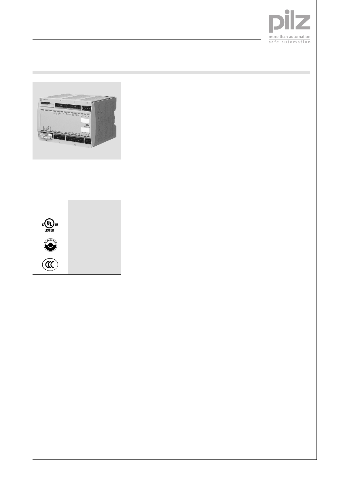
PNOZ m1p
Base units from the PNOZmulti modular safety system
Approvals
PNOZ m1p
Unit features
` Can be configured in the
PNOZmulti Configurator
` Positive-guided relay outputs:
– 1 safety output in accordance
with EN 954-1, Cat. 4
or 2 safety outputs in accordance with EN 954-1, Cat. 2
` Semiconductor outputs:
– 2 safety outputs in accordance
with EN 954-1, Cat. 4
or 4 safety outputs in accordance with EN 954-1, Cat. 3
– 1 auxiliary output
` 4 test pulse outputs
` 1 cascading input and output
can also be used as a standard output
` 20 inputs for connecting:
– E-STOP pushbutton
– Two-hand button
– Safety gate limit switch
– Reset button
– Light barrier
– Scanner
– Enable switch
– PSEN
– Operating mode selector switch
– Safety mat
` Muting function
` Max. 8 expansion modules and 1
fieldbus module can be connected
` LED indicator for:
– Diagnostics
– Supply voltage
– Output circuits
– Input circuits
` Test pulse outputs used to detect
shorts across the inputs
` Monitors shorts between the safety
outputs
` Plug-in connection terminals (either
cage clamp terminal or screw terminal)
Chip card
Chip cards are available with memories of 8 kByte and 32 kByte. For largescale projects we recommend the 32
kByte chip card (see chapter containing the order references).
The chip card with a memory of 32
kByte can only be used from
PNOZ m1p Version 2.0.
Safety features
The relay conforms to the following
safety criteria:
` The circuit is redundant with built-in
self-monitoring.
` The safety function remains effec-
tive in the case of a component failure.
` The relay contacts meet the re-
quirements for safe separation
through increased insulation compared with all other circuits in the
safety system.
` The safety outputs are tested peri-
odically using a disconnection test.
Unit description
The PNOZmulti modular safety system
is used for the safety-related interruption of safety circuits and is designed
for use in:
` Emergency stop equipment
` Safety circuits in accordance with
VDE 0113 Part 1 and EN 60204-1
Pilz GmbH & Co. KG, Sichere Automation, Felix-Wankel-Straße 2, 73760 Ostfildern, Germany
Telephone: +49 711 3409-0, Telefax: +49 711 3409-133, E-Mail: pilz.gmbh@pilz.de
NSG-D-2-359-2006-02
Page 2
Products
Base units
PNOZ m1p
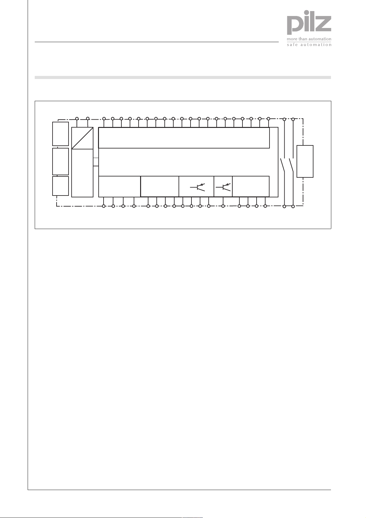
Block diagram
A1 A2
=
Interface
chip card
I0 I19I1 I2 I3 I8I5
=
I4 I9 I12 I13 I14 I15 I16 I17I7 I18I6
Input
I10
I11
13 23
O4 O5
module
Interface
diagnostic
RS 232
Power
Cascading
CI+ CI- CO+
CO-
Test pulse
output
T2T1
module
Interface
expansion
24 V 0 V
O1
O3
O0
O2
OA0
24 V 0 V
14 24
T3T0
Telephone: +49 711 3409-0, Telefax: +49 711 3409-133, E-Mail: pilz.gmbh@pilz.de
NSG-D-2-359-2006-02Pilz GmbH & Co. KG, Sichere Automation, Felix-Wankel-Straße 2, 73760 Ostfildern, Germany
-2
Page 3

Products
Base units
PNOZ m1p
Function description
The function of the inputs and outputs
on the safety system depends on the
safety circuit created using the
PNOZmulti Configurator. A chip card
is used to download the safety circuit
Wiring
The wiring is defined in the circuit diagram in the Configurator. There you
can select the inputs that are to perform a particular safety function and
the outputs that will switch this safety
function.
Please note:
` Information given in the "Technical
details" must be followed.
` Outputs:
– O0 to O5 are safety outputs.
– O4 and O5 are relay outputs
– O0 to O3 are semiconductor out-
puts
– OA0 is an auxiliary output.
` To prevent contact welding, a fuse
should be connected before the
output contacts (see technical details).
` Use copper wire that can withstand
75 °C.
` Sufficient fuse protection must be
provided on all output contacts with
inductive loads.
` Power for the safety system and in-
put circuits must always be provided from a single power supply. The
power supply must meet the regulations for extra low voltages with
safe separation.
` Two connection terminals are avail-
able for each of the supply connections 24 V and 0 V (semiconductor
outputs), plus A1 and A2 (power
supply). This means that the supply
voltage can be looped through several connections. The current at
each terminal may not exceed 9 A.
` Test pulse outputs must exclusively
be used to test the inputs. They
must not be used to drive loads.
Do not route the test pulse lines together with actuator cables within
an unprotected multicore cable.
to the base unit. The base unit has 2
microcontrollers that monitor each
other. They evaluate the input circuits
on the base unit and expansion modules and switch the outputs on the
base unit and expansion modules accordingly.
` Test pulse outputs are also used to
supply safety mats that trigger a
short circuit.
Where test pulses are used for the
safety mat, they may not be reused
for other purposes.
Safety mats are supported from
Version 4.3 of the base unit.
The online help on the PNOZmulti
Configurator contains descriptions of
the operating modes and all the functions of the PNOZmulti safety system,
plus connection examples.
Pilz GmbH & Co. KG, Sichere Automation, Felix-Wankel-Straße 2, 73760 Ostfildern, Germany
Telephone: +49 711 3409-0, Telefax: +49 711 3409-133, E-Mail: pilz.gmbh@pilz.de
NSG-D-2-359-2006-02
Page 4

Products
Base units
PNOZ m1p
Preparing for operation
` Supply voltage
Supply voltage AC DC
For the safety system
(connector X7)
A1
+ 24 V DC
For the semiconductor outputs
(connector X2)
Must always be present, even if the semiconductor outputs are not used
Connection examples
` Input circuit
Input circuit Single-channel Dual-channel
E-STOP
without detection of shorts across contacts
E-STOP
with detection of shorts across contacts
T0
S1
I0
I0
L+
S1
A2
24 V
0 V
I0
I1
T1
T0
0 V
+ 24 V DC
0 V
S1
I0
I1
L+
L+
S1
` Reset circuit
Reset circuit Input circuit without detection of shorts
across contacts
S3
I5
Telephone: +49 711 3409-0, Telefax: +49 711 3409-133, E-Mail: pilz.gmbh@pilz.de
Input circuit with detection of shorts across
contacts
S3
I5
L+
T0
NSG-D-2-359-2006-02Pilz GmbH & Co. KG, Sichere Automation, Felix-Wankel-Straße 2, 73760 Ostfildern, Germany
-4
Page 5

Products
Base units
PNOZ m1p
` Semiconductor outputs
Redundant output
Single output
` Relay outputs
Redundant output
O0 (O2)
O1 (O3)
O0 (O2)
O1 ( O3)
13
O4
14
23
O5
24
K1
K2
K1
K2
K3
K4
K1
K2
L-
L-
L-
L-
L1
N
Single output
` Feedback loop
Feedback loop Redundant output
Contacts from external contactors
O1 (O3, O5)
` Key
S1 E-STOP pushbutton
S3 Reset button
13
O4
14
23
O5
24
O0 (O2, O4)
L1
K2
K1
N
K1
L-
K2
I0
L-
L+
Pilz GmbH & Co. KG, Sichere Automation, Felix-Wankel-Straße 2, 73760 Ostfildern, Germany
Telephone: +49 711 3409-0, Telefax: +49 711 3409-133, E-Mail: pilz.gmbh@pilz.de
NSG-D-2-359-2006-02
Page 6

Products
Base units
PNOZ m1p
Terminal configuration
CHIP-Card
Installation
` The safety system should be in-
stalled in a control cabinet with a
protection type of at least IP54. Fit
the safety system to a horizontal
DIN rail. The venting slots must face
upward and downward. Other
mounting positions could damage
the safety system.
` Use the notches on the back of the
unit to attach it to a DIN rail. Connect the safety system to the DIN
rail in an upright position, so that
the earthing springs on the safety
system are pressed on to the DIN
rail.
` To comply with EMC requirements,
the DIN rail must have a low impedance connection to the control cabinet housing.
Dimensions
94 (3.70")
121 (4.76")
135 (5.31")
Telephone: +49 711 3409-0, Telefax: +49 711 3409-133, E-Mail: pilz.gmbh@pilz.de
NSG-D-2-359-2006-02Pilz GmbH & Co. KG, Sichere Automation, Felix-Wankel-Straße 2, 73760 Ostfildern, Germany
-6
Page 7

Products
Base units
PNOZ m1p
Notice
This data sheet is only intended for use
during configuration. For installation
and operation, please refer to the operating instructions supplied with the
unit.
Maximum capacitive load C (µF)
with load current I (mA) at the semiconductor outputs
C (µF)
6
Service life graph
10
1
D Nennbetriebstrom (A)
GB Nominal operating current (A)
F Courant coupé (A)
0.1
E Corriente nominal de servicio (A)
I Corrente di esercizio nominale (A)
NL Nominale bedrijfsstroom (A)
10 100 1000 10000
D Schaltspielzahl x 10
GB Cycles x 10
F Nombre de manvres x 10
AC15: 230 V
DC13: 24 V
3
AC1: 230 V
3
DC1: 24 V
E Número de ciclos x 10
I Numero dei cicli di commutazione x 10
3
NL Aantal schakelingen x 10
3
3
3
4
2
0
0 10 50 100 200 400 600 800
1000
1200 I (mA)
1400 1600 1800 2000
Technical details
Electrical data
Supply voltage (UB) 24 VDC
Voltage tolerance -15% ... 10%
Power consumption at U
Residual ripple U
B
without load Max. 8.0 W + 2.5 W per expansion module
B
+/- 5 %
Times
Switch-on delay 5 s (after UB is applied)
Simultaneity channel 1/2/3 3 s, two-hand control relay: 0.5 s
Supply interruption before de-energisation Min. 20 ms
Inputs
Number 20
Voltage and current 24 VDC/8 mA
Galvanic isolation
Cascading input
No
500 VAC
Signal level at “0” -3 ... +5 VDC
Signal level at “1” 15 ... 30 VDC
Pilz GmbH & Co. KG, Sichere Automation, Felix-Wankel-Straße 2, 73760 Ostfildern, Germany
Telephone: +49 711 3409-0, Telefax: +49 711 3409-133, E-Mail: pilz.gmbh@pilz.de
NSG-D-2-359-2006-02
Page 8

Products
Base units
PNOZ m1p
Inputs
Input delay 0.6 ... 4 ms
Status indicator LED
Pulsed outputs
Number 4
Voltage and current 24 VDC/0.5 A
Off time during self test < 5 ms
Galvanic isolation No
Short circuit protection Yes
Status indicator LED
Semiconductor outputs
Number
for EN 954-1, 12/96, Cat. 4
for EN 954-1, 12/96, Cat. 3
Switching capability 24 VDC / max. 2 A / max. 48 W
Max. capacitive load See diagram
External supply voltage (U
Voltage tolerance -15% - 10%
Off time during self test < 300 µs
Galvanic isolation Yes
Short circuit protection Yes
Switch-off delay < 30 ms
Residual current at “0” < 0.5 mA
Signal level at “1” U
Status indicator LED
Relay outputs
Number
for EN 954-1, 12/96, Cat. 4
for EN 954-1, 12/96, Cat. 2
Utilisation category in accordance with
EN 60947-4-1, 02/01
EN 60947-5-1, 11/97
Contact fuse protection in accordance with EN 60947-5-1, 08/00
Blow-out fuse
Circuit breaker 24 VDC
Switch-off delay 50 ms
Status indicator LED
Auxiliary outputs
Number 1
Voltage and current 24 VDC / max. 0.5 A / max. 12 W
External supply voltage (U
Voltage tolerance -15% ... +10%
Galvanic isolation Yes
Short circuit protection Yes
Residual current at “0” < 0.5 mA
Signal level at “1” U
Status indicator LED
Cascading output as auxiliary output
Number 1
Voltage and current 24 VDC / max. 0.2 A / max. 4.8 W
Galvanic isolation No
Short circuit protection Yes
Residual current at “0” < 0.5 mA
) 24 VDC
B
) 24 VDC
B
2
4
- 0.5 VDC at 2 A
B
1
2
AC1: 240 V / 6 A / 1440 VA
DC1: 24 V / 6 A / 144 W
AC15: 230 V / 3 A / 690 VA
DC13: 24 V / 3 A / 72 W
6 A quick or slow
6 A (characteristic B + C)
- 0.5 VDC at 0.5 A
B
Telephone: +49 711 3409-0, Telefax: +49 711 3409-133, E-Mail: pilz.gmbh@pilz.de
NSG-D-2-359-2006-02Pilz GmbH & Co. KG, Sichere Automation, Felix-Wankel-Straße 2, 73760 Ostfildern, Germany
-8
Page 9

Products
Base units
PNOZ m1p
Environmental data
Airgap creepage between
relay contacts
Relay contacts and other safe circuits
Vibration in accordance with EN 60068-2-6, 04/95
Frequency:
Amplitude:
Climatic suitability DIN IEC 60068-2-3, 12/86
EMC EN 60947-5-1, 01/00
Ambient temperature
With UL approval
Without UL approval (with forced convection)
Storage temperature -25 ... + 70 °C
Mechanical data
Protection type
Mounting (e.g. cabinet)
Housing
Terminals
DIN rail
Top hat rail
Recess width
Maximum cable runs
Per input
Sum of individual cable runs at the test pulse output
Cable cross section
Rigid single-core, flexible multi-core or multi-core
with crimp connector
Power supply (X7), inputs (X5, X6), semiconductor outputs (X2), test
pulse outputs (X1)
auxiliary output (X2), cascading output
Relay outputs (X3)
Flexible multi-core with plastic sleeve
Relay outputs (X3)
Torque setting for connection terminals (screws)
Power supply (X7), inputs (X5, X6), semiconductor outputs (X2), test
pulse outputs (X1),
auxiliary output (X2), cascading output
Relay outputs (X3)
Housing material
Housing
Front
Dimensions (H x W x D) 94 x 135 x 121 mm
Weight with connector 530 g
DIN VDE 0110-1, 04/97
3 mm
5.5 mm
10 ... 55 Hz
0.35 mm
0 ... + 55 °C
0 ... + 60 °C
IP54
IP20
IP20
35 x 7.5 EN 50022
27 mm
1 km
40 km
0.5 ... 1.5 mm2
0.5 ... 2.5 mm2
0.5 ... 1.5 mm2
0.2 ... 0.25 Nm
0.4 ... 0.5 Nm
PPO UL 94 V0
ABS UL 94 V0
Order reference
Type Features Order no.
PNOZ m1p Base unit 773 100
Pilz GmbH & Co. KG, Sichere Automation, Felix-Wankel-Straße 2, 73760 Ostfildern, Germany
Telephone: +49 711 3409-0, Telefax: +49 711 3409-133, E-Mail: pilz.gmbh@pilz.de
NSG-D-2-359-2006-02
 Loading...