

Pilz PNOZ m0p, PNOZ m1p Operating Instructions Manual

20 878-06
PNOZ m0p, PNOZ m1p, PNOZ m1p coated version
4
D Betriebsanleitung
4
GB Operating instructions
4
F Manuel d`utilisation
Das Basisgerät PNOZ m0p/
PNOZ m1p
Das Basisgerät PNOZ m0p/PNOZ m1p
(coated version) des modularen Sicher-
heitssystems PNOZmulti dient dem
sicherheitsgerichteten Unterbrechen von
Sicherheitsstromkreisen.
Das Gerät ist bestimmt für den Einsatz in:
• NOT-AUS-Einrichtungen
• Sicherheitsstromkreisen nach VDE 0113
Teil 1, 11/98 und EN 60204-1, 12/97
(z. B. bei beweglichen Verdeckungen)
Das PNOZ m0p kann nur ohne
Erweiterungsmodule betrieben werden.
Lieferumfang:
• Basisgerät PNOZ m0p, PNOZ m1p oder
PNOZ m1p coated version
• Abschlussstecker:
- PNOZ m1p: 779 110
- PNOZ m1p coated version: 779 112
Zu Ihrer Sicherheit
Das Basisgerät PNOZ m0p/PNOZ m1p
(coated version) erfüllt alle notwendigen
Bedingungen für einen sicheren Betrieb.
Beachten Sie jedoch nachfolgend aufgeführte Sicherheitsbestimmungen:
• Installieren und nehmen Sie das Gerät nur
dann in Betrieb, wenn Sie mit dieser
Betriebsanleitung und den geltenden
Vorschriften über Arbeitssicherheit und
Unfallverhütung vertraut sind.
• Diese Betriebsanleitung beschreibt
lediglich die Grundfunktionen des Geräts.
Die erweiterten Funktionen wie z. B.
Kaskadierung sind in der Online-Hilfe des
PNOZmulti Configurators und in dem
technischen Katalog PNOZmulti beschrieben. Verwenden Sie diese Funktionen nur,
wenn Sie diese Dokumentationen gelesen
und verstanden haben. Alle notwendigen
Dokumentationen sind auf der CD
PNOZmulti Configurator enthalten.
• Verwenden Sie das Gerät nur gemäß
seiner Bestimmung. Beachten Sie dazu
auch die Werte im Abschnitt "Technische
Daten".
• Halten Sie beim Transport, bei der
Lagerung und im Betrieb die Bedingungen
nach EN 60068-2-6 ein (siehe "Technische
Daten").
• Sorgen Sie bei allen induktiven Verbrauchern für eine ausreichende
Schutzbeschaltung.
• Öffnen Sie nicht das Gehäuse und
nehmen Sie auch keine eigenmächtigen
Umbauten vor.
• Schalten Sie bei Wartungsarbeiten (z. B.
beim Austausch von Schützen) unbedingt
die Versorgungsspannung ab.
Beachten Sie unbedingt die Warnhinweise in
den anderen Abschnitten dieser Anleitung.
Diese Hinweise sind optisch durch Symbole
hervorgehoben.
The PNOZ m0p/PNOZ m1p base
module
The PNOZ m0p/PNOZ m1p (coated
version) base module from the PNOZmulti
modular safety system is used for the safetyrelated interruption of safety circuits.
The unit is designed for use in:
• E-STOP installations
• Safety circuits in accordance with
VDE 0113 Part 1, 11/98 and EN 60204-1,
12/97 (e.g. on movable guards)
The PNOZ m0p can only be used without
expansion modules.
Range:
• PNOZ m0p, PNOZ m1p or PNOZ m1p
base module coated version
• Terminators:
- PNOZ m1p: 779 110
- PNOZ m1p coated version: 779 112
For your safety
The PNOZ m0p/PNOZ m1p base module
(coated version) meets all of the conditions
necessary for safe operation.
However, always ensure the following safety
requirements are met:
• Only install and commission the unit if you
are familiar with both this operating
manual and the current regulations for
health and safety at work and accident
prevention.
• This operating manual only describes the
basic functions of the unit. Information on
the expanded functions such as cascading
can be found in the online help for the
PNOZmulti Configurator and in the
PNOZmulti technical catalogue. Use these
functions only after you have read and
understood the documentation. All
necessary documentation can be found on
the PNOZmulti Configurator CD.
• Only use the unit in accordance with its
intended purpose. Please also take note of
the values in the "Technical details"
section.
• Transport, storage and operating conditions should all conform to EN 60068-2-6
(see "Technical details").
• Adequate protection must be provided for
all inductive consumers.
• Do not open the housing or undertake any
unauthorised modifications.
• Please make sure you shut down the
supply voltage when performing mainte-
nance work (e. g. exchanging contactors).
You must take note of the warnings given in
other sections of this manual. These are
highlighted visually through the use of
symbols.
Important: Failure to keep to these
safety regulations will render the
warranty invalid.
L’appareil de base PNOZ m0p/
PNOZ m1p
L’appareil de base PNOZ m0p/PNOZ m1p
(coated version) du système de sécurité
modulaire PNOZmulti sert à interrompre en
toute sécurité des circuits de sécurité.
L’appareil est conçu pour les applications
suivantes :
• Circuits d’arrêt d’urgence
• Circuits de sécurité selon les normes
VDE 0113-1, 11/98 et EN 60204-1, 12/97
(p. ex. pour protections mobiles)
L’exploitation du PNOZ m0p n’est possible
que sans module d’extension.
Contenu de la livraison :
• Appareil de base PNOZ m0p, PNOZ m1p
ou PNOZ m1p coated version
• Fiches de terminaison :
- PNOZ m1p : 779 110
- PNOZ m1p coated version : 779 112
Pour votre sécurité
L’appareil de base PNOZ m0p/PNOZ m1p
(coated version) satisfait à toutes les conditions
nécessaires pour un fonctionnement sûr.
Toutefois, vous êtes tenu de respecter les
prescriptions de sécurité suivantes :
• Vous n’installerez l’appareil et ne le mettrez
en service qu’après vous être familiarisé
avec le présent manuel d’utilisation et les
prescriptions en vigueur sur la sécurité du
travail et la prévention des accidents.
• Ce manuel d’utilisation ne décrit que les
fonctions de base de l’appareil. Les
fonctions étendues, comme par ex. la mise
en cascade, sont décrites dans l’aide en
ligne du configurateur PNOZmulti ainsi
que dans le catalogue technique
PNOZmulti. N’utilisez ces fonctions
qu’après avoir lu et compris cette documentation. Toute la documentation
nécessaire se trouve sur le CD du
configurateur PNOZmulti.
• N’utilisez l’appareil que conformément à
l’usage auquel il est destiné. À ce sujet,
respectez les valeurs indiquées dans les
"Caractéristiques techniques".
• Pour le transport, le stockage et l’utilisation, respectez les exigences de la norme
EN 60068-2-6 (voir "Caractéristiques
techniques").
• Veillez à ce que tous les consommateurs
inductifs disposent d’un circuit de protection suffisant.
• N’ouvrez pas le boîtier et n’effectuez pas
de modifications non autorisées.
• En cas de travaux de maintenance (par
ex. remplacement des contacteurs),
coupez impérativement la tension
d’alimentation.
Respectez impérativement les avertissements
dans les autres paragraphes du présent
manuel d’utilisation. Ces avertissements sont
signalés par des symboles visuels.
Wichtig: Beachten Sie die Sicherheitsbestimmungen, sonst erlischt
jegliche Gewährleistung.
Important : respectez les consignes
de sécurité, sinon la garantie devient
caduque.
- 1 -

Gerätebeschreibung
Sicherheitseigenschaften:
Das Basisgerät erfüllt folgende Sicherheitsanforderungen:
• Die Schaltung ist redundant mit Selbstüberwachung aufgebaut.
• Die Sicherheitseinrichtung bleibt auch bei
Ausfall eines Bauteils wirksam.
• Die Sicherheitsausgänge werden durch
einen Abschalttest periodisch geprüft.
• Die Relaiskontakte erfüllen die Anforderungen für sichere Trennung durch
verstärkte Isolierung gegenüber allen
anderen Stromkreisen des Sicherheitssystems.
Gerätemerkmale:
• 20 Eingänge für den Anschluss von NOTAUS, Zweihand-Taster, Schutztür,
Lichtvorhang, Scanner, Zustimmungsschalter, PSEN, Betriebsartenwahlschalter
• Ausgänge in Halbleitertechnik:
- 2 Sicherheitsausgänge nach
EN 954-1, 12/96, Kat. 4 oder
4 Sicherheitsausgänge nach
EN 954-1, 12/96, Kat. 3
- 1 Hilfsausgang
• Relaisausgänge:
1 Sicherheitskontakt nach
EN 954-1, 12/96, Kat. 4 oder
2 Sicherheitskontakte nach
EN 954-1, 12/96, Kat. 2
• 4 Taktausgänge
• 1 Kaskadiereingang und -ausgang, Kat. 4
• konfigurierbar mit PNOZmulti Configurator
• max. 8 Erweiterungsmodule anschließbar
(nur PNOZ m1p, PNOZ m1p coated
version)
• Statusanzeigen
• Querschlussüberwachung durch Taktausgänge an den Eingängen
• Querschlussüberwachung zwischen den
Sicherheitsausgängen
• steckbare Klemmen, wahlweise mit
Käfigzugfederanschluss oder
Schraubanschluss
Unit description
Safety features:
The base module meets the following safety
requirements:
• The circuit is redundant with built-in selfmonitoring.
• The safety function remains effective even
in the case of a component failure.
• The safety outputs are tested periodically
using a disconnection test.
• The relay contacts meet the requirements
for safe separation by increased insulation
compared to all other circuits in the safety
system.
Unit features:
• 20 inputs for connecting E-STOP, twohand buttons, safety gate, light curtain,
scanner, enable switch, PSEN, operating
mode selector switch
• Outputs with semiconductor technology:
- 2 safety outputs in accordance with
EN 954-1, 12/96, Cat. 4 or
4 safety outputs in accordance with
EN 954-1, 12/96, Cat. 3
- 1 auxiliary output
• Relay outputs:
1 safety contact in accordance with
EN 954-1, 12/96, Cat. 4 or
2 safety contacts in accordance with
EN 954-1, 12/96, Cat. 2
• 4 test pulse outputs
• 1 cascading input and output, Cat. 4
• Can be configured using the PNOZmulti
Configurator
• Max. 8 expansion modules can be
connected (only PNOZ m1p, PNOZ m1p
coated version)
• Status indicators
• Test pulse outputs used to detect shorts
across the inputs
• Monitoring of shorts between the safety
outputs
• Plug-in terminals, either with cage clamp
connection or screw connection
Description de l’appareil
Caractéristiques de sécurité :
L’appareil de base satisfait aux exigences de
sécurité suivantes :
• Conception redondante avec autosurveillance.
• Le dispositif de sécurité reste actif, même
en cas de défaillance d’un composant.
• Les sorties de sécurité sont testées
périodiquement à l’aide d’un test de
coupure.
• Les contacts de relais satisfont aux
exigences relatives à l’isolation de sécurité
par une isolation renforcée par rapport à
tous les autres circuits du système de
sécurité.
Caractéristiques de l’appareil :
• 20 entrées pour brancher : arrêt
d'urgence, poussoir de commande
bimanuelle, porte de protection, barrière
immatérielle, scanner, poignée d’assentiment, PSEN, sélecteur de modes de
marche
•
Sorties avec technologie semi-conducteur :
- 2 sorties de sécurité selon
EN 954-1, 12/96, cat. 4 ou
4 sorties de sécurité selon
EN 954-1, 12/96, cat. 3
- 1 sortie d’information
• Sorties de relais :
1 contact de sécurité selon
EN 954-1, 12/96, cat. 4 ou
2 contacts de sécurité selon
EN 954-1, 12/96, cat. 2
• 4 sorties impulsionnelles
• 1 entrée/sortie en cascade, cat. 4
• Paramétrable avec le configurateur
PNOZmulti
• Possibilité de raccorder jusqu’à 8 modules
d’extension (seulement PNOZ m1p,
PNOZ m1p coated version)
• Affichages d’état
• Surveillance des courts-circuits par sorties
impulsionnelles aux entrées
• Surveillance des courts-circuits entre les
sorties de sécurité
• borniers débrochables, au choix avec
raccordement à vis ou à ressort
Funktionsbeschreibung
Arbeitsweise:
Die Funktionsweise der Ein- und Ausgänge
des Sicherheitssystems hängt von der mit
dem PNOZmulti Configurator erstellten
Sicherheitsschaltung ab. Die Sicherheitsschaltung wird mit Hilfe einer Chipkarte oder
über die serielle Schnittstelle RS 232 (NullModem-Kabel) auf die Chipkarte in das
Basisgerät übertragen.
Das Basisgerät hat 2 Micro-Controller, die
sich gegenseitig überwachen. Sie werten die
Eingangskreise des Basisgeräts und der
Erweiterungsmodule aus und schalten
abhängig davon die Ausgänge des Basisgeräts und der Erweiterungsmodule. Die
LEDs an Basisgerät und Erweiterungsmodulen zeigen den Status des Sicherheitssystems PNOZmulti an.
Erweiterte Funktionen:
Diagnose
Die Status- und Fehlermeldungen, die die
LEDs anzeigen, werden in einem FehlerStack gespeichert. Dieser Fehler-Stack kann
vom PNOZmulti Configurator über die
RS 232-Schnittstelle ausgelesen werden.
Eine umfangreichere Diagnose ist über die
RS 232-Schnittstelle oder eines der Feldbusmodule, z. B. das PROFIBUS-Modul,
möglich.
Function description
Operation:
The function of the inputs and outputs on the
safety system depends on the safety circuit
created using the PNOZmulti Configurator.
The safety circuit is transferred to the chip
card in the base module via a chip card or
the RS 232 interface (null modem cable).
The base module has 2 microcontrollers that
monitor each other. They evaluate the input
circuits on the base module and expansion
modules and switch the outputs on the base
module and expansion modules accordingly.
The LEDs on the base module and expansion modules indicate the status of the
PNOZmulti safety system.
Expanded functions:
Diagnostics
The status and error messages shown by the
LEDs are saved in an error stack. This error
stack can be read out from PNOZmulti
Configurator via the RS 232 interface.
A more comprehensive diagnosis can be
made using the RS 232 interface or one of
the fieldbus modules, e.g. the PROFIBUS
module.
Description du fonctionnement
Fonctionnement :
Le fonctionnement des entrées et des sorties
du système de sécurité dépend du circuit de
sécurité créé avec le configurateur
PNOZmulti. Le circuit de sécurité est
transféré à l’appareil de base à l’aide d’une
carte à puce ou par le biais de l’interface
série RS 232 (câble null-modem) à la carte à
puce de l’appareil de base.
L’appareil de base possède 2 micro-contrôleurs
qui se contrôlent mutuellement.
circuits d’entrée de l’appareil de base et des
modules d’extension, et activent en conséquence les sorties de l’appareil de base et
des modules d’extension. Les LED sur
l’appareil de base et les modules d’extension
indiquent l’état du système de sécurité
PNOZmulti.
Fonctions étendues :
Diagnostic
Les messages d’état et d’erreur indiqués par
les LED sont enregistrés dans une pile
d’erreur. Cette pile d’erreur peut être lue par
le configurateur PNOZmulti par le biais de
l’interface RS 232.
Un diagnostic plus complet peut être effectué
par l’interface RS 232 ou l’un des modules
bus de terrain, comme par ex. le module
PROFIBUS.
Ils évaluent les
- 2 -
Kaskadierung
Die Kaskadierein- und -ausgänge ermöglichen das Vernetzen mehrerer PNOZmultiund PNOZelog-Geräte in Reihe oder als
Baumstruktur.
Cascading
The cascading inputs and outputs allow
several PNOZmulti and PNOZelog units to
be connected in series or connected as a
tree structure.
Mise en cascade
Les entrées et les sorties en cascade
permettent la mise en réseau en série ou
sous forme de structure arborescente de
plusieurs appareils PNOZmulti et PNOZelog.
Info! Ausführliche Informationen zu
diesen Funktionen und
Anschlussbeispiele finden Sie in der
Online-Hilfe des PNOZmulti
Configurators und dem technischen
Katalog PNOZmulti.
CI+ CI- CO+CO-
Mise en cascade
Interface
Chipkarte
chip card
carte à puce
Interface
Diagnosemodul
diagnostic module
module de
diagnostic
X4
RS 232
Kaskadierung
Cascading
Information! Detailed information on
these functions and connection
examples can be found in the online
help for the PNOZmulti Configurator
and in the PNOZmulti technical
catalogue.
X1 X2 X3
T0
T1 T2 T3
Taktausgänge
Test pulse outputs
Sorties
impulsionnelles
µController
µController
Eingänge
Inputs
Entrées
Halbleiterausgänge, Hilfsausgang,
Versorgungsanschlüsse
Semiconductor outputs,
auxiliary output, supply connections
Sorties statiques, sorties information,
bornes d'alimentation
0 V
24 VOA0O3O2O1O0
Information ! Vous trouverez des
informations détaillées sur ces
fonctions ainsi que des exemples de
raccordement dans l’aide en ligne du
configurateur PNOZmulti et dans le
catalogue technique PNOZmulti.
O4 O5
13 14 23
Relaisausgänge
Relay outputs
Sorties de relais
Netzteil
Power supply
Alimentation
24
Interface
Erweiterungsmodule
expansion modules
modules d'extension
I19 A1
X6X5 X7
I18I17I16I15I14I13I12I11I10I9I8I7I6I5I4I3I2I1I0
A1 A2 A2
Fig. 1 Innenschaltbild Fig. 1: Internal wiring diagram Fig. 1: Schéma interne
Sicherheitssystem montieren
Beachten Sie bei der Montage:
Installing the safety system
Please note for installation:
Installer le système de sécurité
Pour le montage, respectez les consignes
suivantes :
Achtung! Durch elektrostatische
Entladung können Bauteile des
Sicherheitssystems beschädigt
werden. Sorgen Sie für Entladung,
bevor Sie das Sicherheitssystem
berühren, z. B. durch Berühren einer
geerdeten, leitfähigen Fläche oder
durch Tragen eines geerdeten
Armbands.
• Montieren Sie das Sicherheitssystem in
einen Schaltschrank mit einer Schutzart
von mindestens IP54.
Montieren Sie das Sicherheitssystem auf
eine waagrechte Normschiene. Die
Lüftungsschlitze müssen nach oben und
unten zeigen. Andere Einbaulagen können
zur Zerstörung des Sicherheitssystems
führen (siehe Fig. 2).
• Befestigen Sie das Sicherheitssystem mit
Hilfe der Rastelemente auf der Rückseite
auf einer Normschiene. Führen Sie das
Sicherheitssystem gerade auf die Normschiene, so dass die Erdungsfedern am
Sicherheitssystem auf die Normschiene
gedrückt werden.
• Um die EMV-Anforderungen einzuhalten,
muss die Normschiene mit dem Schalt-
Caution! Electrostatic discharge can
damage components on the safety
system. Ensure against discharge
before touching the safety system,
e.g. by touching an earthed,
conductive surface or by wearing an
earthed armband.
• The safety system should be installed in a
control cabinet with a protection type of at
least IP54.
Fit the safety system to a horizontal DIN
rail. The venting slots must point up and
down. Other mounting positions could
damage the safety system (see Fig. 2).
• Use the notches on the back of the safety
system to attach it to a DIN rail. Connect
the safety system to the DIN rail in an
upright position so that the earthing
springs on the safety system are pressed
on to the DIN rail.
• To comply with EMC requirements, the
DIN rail must have a low-impedance
connection to the control cabinet housing.
Attention ! Une décharge électrostatique peut endommager les éléments
du système de sécurité. Veillez à
vous décharger avant de toucher le
système de sécurité, par ex. en
touchant une surface conductrice
mise à la terre ou en portant un
bracelet de mise à la terre.
• Montez le système de sécurité dans une
armoire d’indice de protection IP 54 au
moins.
Montez le système de sécurité sur un rail
DIN horizontal. Les ouïes de ventilation
doivent être orientées vers le haut et vers
le bas. D’autres positions de montage
pourraient provoquer une perturbation du
système de sécurité (voir Fig. 2).
• Accrochez le système de sécurité sur un
rail DIN à l’aide des ergots à l’arrière de
l’appareil. Installez le système de sécurité
droit sur le rail DIN de sorte que les
ressorts de mise à la terre du système de
sécurité reposent sur le rail DIN.
• Pour respecter les exigences CEM, le rail
DIN doit être relié par une liaison à basse
impédance au corps de l’armoire.
schrankgehäuse niederohmig verbunden
sein.
- 3 -
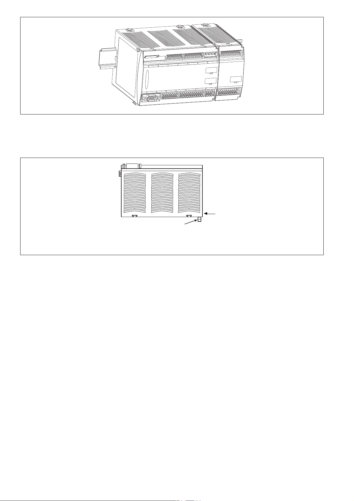
Fig. 2: Sicherheitssystem montieren
Installing the safety system
Installer le système de sécurité
Basisgerät ohne Erweiterungsmodule
montieren
Stecken Sie den Abschlussstecker auf die
mit "Termination/Link" gekennzeichnete Seite
des Basisgeräts.
Fig. 3: Basisgerät montieren
Installing the base module
Monter l’appareil de base
Basisgerät und Erweiterungsmodule
verbinden (nur PNOZ m1p, PNOZ m1p
coated version)
Die Module werden mit Steckbrücken
verbunden. Es dürfen max. 8 Erweiterungsmodule und ein Feldbusmodul an ein
Basisgerät angeschlossen werden.
Auf der Geräterückseite des Basisgeräts
PNOZ m1p befinden sich 2 Stiftleisten.
• Stellen Sie sicher, dass kein Abschlussstecker gesteckt ist (siehe Fig. 3).
• Verbinden Sie das Basisgerät, die
Erweiterungsmodule und das Feldbusmodul mit den mitgelieferten Steckbrücken
(siehe Fig. 4).
• Stecken Sie den Abschlussstecker auf das
letzte Erweiterungsmodul.
• Wird kein Feldbusmodul montiert, darf auf
die freie Stiftleiste am Grundgerät kein
Abschlussstecker gesteckt werden.
Install base module without expansion
modules
Connect the terminator to the side of the
base unit designated as the "Termination/
Link" side.
Abschlussstecker
Terminator
Fiche de terminaison
Connect the base module and expansion
modules (only PNOZ m1p, PNOZ m1p
coated version)
The modules are linked via jumpers. A max.
of 8 expansion modules and one fieldbus
module may be connected to a base module.
There are 2 pin connectors on the rear of the
PNOZ m1p base module.
• Ensure that no terminator is connected
(see Fig. 3).
• Connect the base module, the expansion
modules and the fieldbus module using the
jumpers supplied (see Fig. 4).
• The terminator must be fitted to the last
expansion module.
• If a fieldbus module is not installed, a
terminator must not be connected to the
free pin connector on the base module.
Monter l’appareil de base sans module
d’extension
Branchez la fiche de terminaison sur le côté
de l’appareil de base repéré par
"Termination/Link".
Aufdruck/Imprint/Inscription :
Termination/Link
Relier l’appareil de base et les modules
d’extension (seulement PNOZ m1p,
PNOZ m1p coated version)
Les modules sont reliés par des cavaliers de
pontage. Huit modules d’extension et un
module bus de terrain au maximum peuvent
être reliés à un appareil de base.
La face arrière de l’appareil de base
PNOZ m1p comporte 2 broches.
• Assurez-vous qu’aucune fiche de terminaison n’est branchée (voir Fig. 3).
• Reliez l’appareil de base, les modules
d’extension et le module bus de terrain
avec les cavaliers de pontage livrés avec
les appareils (voir Fig. 4).
• Branchez la fiche de terminaison sur le
dernier module d’extension.
• Si aucun module bus de terrain n’est
monté, aucune fiche de terminaison ne
doit être branchée sur la broche libre de
l’appareil de base.
- 4 -
 Loading...