

Page 1

21 362-3FR-03
PNOZ e4.1p
4
D Betriebsanleitung
4
GB Operating instructions
4
F Manuel d'utilisation
Sicherheitsschaltgerät PNOZ e4.1p
Das Sicherheitsschaltgerät PNOZ e4.1p
dient dem sicherheitsgerichteten Unterbrechen eines Sicherheitsstromkreises. Das
Gerät erfüllt die Forderungen der EN 954-1
oder EN ISO 13849-1 bis Kategorie 3. Es
darf ausschließlich als Sicherheitssystem
zusammen mit Schaltmatten des Typs
SM/BK nach dem Funktionsprinzip
4-Leiter-Technik (ohne Überwachungswiderstand) der Fa. Mayser eingesetzt
werden. Das Sicherheitsschaltgerät dient
dabei nach EN 1760-1 zur Signalverarbeitung und als Ausschalteinrichtung.
Wichtige Daten für Projektierung und
Anwendung finden Sie auch im technischen
Katalog PNOZelog.
Zu Ihrer Sicherheit
Das Sicherheitsschaltgerät PNOZ e4.1p
erfüllt alle notwendigen Bedingungen für
einen sicheren Betrieb.
Beachten Sie jedoch nachfolgend aufgeführte Sicherheitsbestimmungen:
• Installieren und nehmen Sie das Sicherheitssystem nur dann in Betrieb, wenn
Sie diese Betriebsanleitung, den technischen Katalog und die Montageanleitung
der Fa. Mayser gelesen und verstanden
haben. Sie müssen außerdem mit den
geltenden Vorschriften über Arbeitssicherheit und Unfallverhütung vertraut
sein.
• Verwenden Sie das Gerät nur gemäß
seiner Bestimmung. Beachten Sie dazu
auch die Werte im Abschnitt “Technische
Daten”.
• Halten Sie beim Transport, bei der
Lagerung und im Betrieb die Bedingungen ein, wie sie unter "Technische Daten"
angegeben sind.
• Öffnen Sie nicht das Gehäuse und
nehmen Sie auch keine eigenmächtigen
Umbauten vor.
• Schalten Sie bei Wartungsarbeiten (z. B.
beim Austausch von Schützen) unbedingt
die Versorgungsspannung ab oder
brücken Sie die Eingangskreise, sonst
kann das Gerät bei Verdrahtungsfehlern
unerwartet einschalten.
Beachten Sie unbedingt die Warnhinweise
in den anderen Abschnitten dieser Anleitung. Diese Hinweise sind optisch durch
Symbole hervorgehoben.
Wichtig: Beachten Sie die Sicherheitsbestimmungen, sonst erlischt
jegliche Gewährleistung.
Safety relay PNOZ e4.1p
The safety relay PNOZ e4.1p is used for the
safety-related interruption of a safety circuit.
The unit meets requirements of EN 954-1 or
EN ISO 13849-1 up to category 3. It may
only be used as a safety system in
conjunction with Mayser SM/BK type
safety mats in accordance with the 4-wire
technology operating principle (without
monitoring resistor). The safety relay is
used for signal processing and as a
shutdown device in accordance with
EN 1760-1.
Important data for project planning and
application can also be found in the
PNOZelog technical catalogue.
For your safety
The PNOZ e4.1p safety relay meets all the
necessary conditions for safe operation.
However, please note the following safety
regulations:
• Do not install and commission the safety
system until you have read and understood these operating instructions, the
technical catalogue and the installation
manual from Mayser. You must also be
familiar with the relevant regulations
concerning health and safety at work and
accident prevention.
• Only use the unit for the purpose for
which it is intended. Please also take note
of the values in the "Technical details"
section.
• Transport, storage and operating
conditions should all conform to the
standards as stated under “Technical
details”.
• Do not open the housing or undertake any
unauthorised modifications.
• Please make sure you shut down the
supply voltage or link the input circuits
when performing maintenance work
(e.g. when replacing contactors),
otherwise the unit might switch on
unexpectedly in the case of a wiring error.
You must take note of the warnings given in
other sections of these operating
instructions. These are highlighted visually
through the use of symbols.
Notice: Failure to keep to these
safety regulations will render the
warranty invalid.
Bloc logique de sécurité PNOZ e4.1p
Le bloc logique de sécurité PNOZ e4.1p
sert à interrompre en toute sécurité un
circuit de sécurité. Ce bloc logique satisfait
aux exigences de la norme EN 954-1,
EN ISO 13849-1 jusqu’à la catégorie 3. Il ne
doit être utilisé comme système de sécurité
qu’avec les tapis sensibles de type SM/BK
raccordé selon le principe fonctionnel de
la technique à 4 conducteurs (sans
résistance de surveillance) de la société
Mayser. Le bloc logique de sécurité est
alors utilisé selon la norme EN 1760-1 pour
le traitement des signaux et comme
dispositif de coupure.
Vous trouverez également des données
importantes pour la configuration projet et
l’utilisation dans le Catalogue technique
PNOZelog.
Pour votre sécurité
Le bloc logique de sécurité PNOZ e4.1p
satisfait à toutes les conditions nécessaires
pour un fonctionnement sûr.
Toutefois, vous êtes tenu de respecter les
prescriptions de sécurité suivantes :
• Ne procédez à l’installation et à la mise
en service du système de sécurité que si
vous avez lu et compris cette notice
d’utilisation, le catalogue technique et les
instructions de montage de la société
Mayser. En outre, vous devez être
familiarisé avec les prescriptions en
vigueur concernant la sécurité du travail
et la prévention des accidents.
• N'utilisez l'appareil que conformément à
l'usage auquel il est destiné. À ce sujet
respectez les valeurs indiquées dans les
"Caractéristiques techniques".
• Pour le transport, le stockage et
l'utilisation, respectez les exigences des
normes specifiées (voir „Caractéristiques
techniques“).
• N’ouvrez pas le boîtier et n’effectuez pas
de modifications non autorisées.
• En cas de travaux de maintenance (par
ex. remplacement des contacteurs),
coupez impérativement la tension
d’alimentation ou ouvrez les circuits
d’entrée, sinon un enclenchement inopiné
de l’appareil est possible en cas d’erreur
de câblage.
Respectez impérativement les
avertissements dans les autres paragraphes
du présent manuel d’utilisation. Ces
avertissements sont signalés par des
symboles visuels.
Important : respectez les consignes
de sécurité, sinon la garantie devient
caduque.
- 1 -
Page 2

Gerätebeschreibung
Sicherheitseigenschaften
Das Schaltgerät erfüllt folgende Sicherheitsanforderungen:
• Das Sicherheitssystem erfüllt bezüglich
eines Fehlerfalls die Anforderungsklasse
AK6 nach DIN VDE 0801 (Kategorie 4
nach EN 954-1). Die Schaltmatte erfüllt
diese Anforderung nur bedingt (siehe
Abschnitt 4.15 der DIN EN 1760-1).
• Die Schaltung ist redundant mit Selbstüberwachung aufgebaut.
• Die Sicherheitseinrichtung bleibt auch bei
Ausfall eines Bauteils wirksam.
• Die Sicherheitsausgänge werden durch
einen Abschalttest periodisch geprüft.
• Das Gerät besitzt eine elektronische
Sicherung.
Gerätemerkmale
• Ausgänge in Halbleitertechnik:
2 Sicherheitsausgänge, 1 Hilfsausgang
und 2 Taktausgänge
• Anschlussmöglichkeit für Schaltmatten
vom Typ SM/BK der Fa. Mayser
• Hilfsausgang umschaltbar als Diagnoseausgang
• UND- und ODER-Eingang zur logischen
Verknüpfung mehrerer Geräte
• Querschlussüberwachung durch Taktausgänge
• Statusanzeige
• Rückführkreise zur Überwachung
externer Schütze
Unit description
Safety features
The relay meets the following safety
requirements:
• In the case of an error, the safety system
complies with requirement class AK6 as
per DIN VDE 0801 (category 4 as per
EN 954-1). The safety mat meets this
requirement only under certain conditions
(see section 4.15 of DIN EN 1760-1).
• The circuit is redundant with built-in selfmonitoring.
• The safety function remains effective
even in the case of a component failure.
• The safety outputs are tested periodically
using a disconnection test.
• The unit has an electronic fuse.
Unit features
• Outputs using semiconductor technology:
2 safety outputs, 1 auxiliary output and
2 test pulse outputs
• Ability to connect Mayser SM/BK type
safety mats
• Auxiliary output can be used as a
diagnostic output
• AND/OR input for logic connections
between several units
• Test pulse outputs monitor shorts across
the input contacts
• Status display
• Feedback loops for monitoring external
contactors
Description de l’appareil
Propriétés de sécurité
Le bloc logique satisfait aux exigences de
sécurité suivantes :
• Le système de sécurité répond à la
classe d’exigence AK6 de la norme
DIN VDE 0801 (Catégorie 4 selon
EN 954-1) en ce qui concerne un cas
d’erreur. Le tapis sensible ne répond que
sous condition à ces exigences (voir
section 4.15 de la norme DIN EN 1760-1).
• La conception du circuit est redondante
avec autosurveilance.
• Le dispositif de sécurité reste actif, même
en cas de défaillance d’un composant.
• Les sorties de sécurité sont testées
périodiquement à l’aide d’un test de
coupure.
• L’appareil est équipé d’un fusible
électronique.
Caractéristiques de l’appareil
• Sorties statiques :
2 sorties de sécurité, 1 sortie
d’information et 2 sorties impulsionnelles
• Possibilité de raccordement des tapis
sensibles de type SM/BK de la société.
Mayser
• Sortie d’information commutable en sortie
de diagnostic
• Entrées ET et OU pour le couplage
logique de plusieurs appareils
• Surveillance des courts-circuits par
sorties impulsionnelles
• Affichage de l’état
• Boucle de retour pour le contrôle des
contacteurs externes
Funktionsbeschreibung
Arbeitsweise
Zwei Mikro-Controller werten die Eingangskreise aus und schalten abhängig davon die
Ausgänge. Die Mikro-Controller überwachen
sich gegenseitig.
Zustand der Ausgänge
• Schaltmatte nicht betreten:
An den Sicherheitsausgängen 14 und 24
und dem Hilfsausgang Y32 liegen HighSignale.
• Schaltmatte betreten:
An den Sicherheitsausgängen 14 und 24
und dem Hilfsausgang Y32 liegen LowSignale.
Funktionen
• Wenn an den Eingang Y5 für mindestens
250 ms ein High-Signal (+24 V DC) gelegt
wird, wechselt der Ausgang Y32 in die
Diagnosefunktion. Die Ansteuerung
erfolgt über einen Treiber, der als
Zubehör zur Verfügung steht oder selbst
erstellt werden kann. Ist der Eingang Y5
offen oder Low, funktioniert Y32 wie ein
Hilfsausgang.
• Zur logischen Verknüpfung mehrerer
Geräte besitzt das PNOZ e4.1p einen
UND- und einen ODER-Eingang. Die
Eingänge weisen Schaltverzögerungen
auf. Werden mehrere Geräte UNDverknüpft addieren sich diese Zeiten.
Function description
Operation
Two microcontrollers evaluate the input
circuits and switch the outputs accordingly.
The microcontrollers monitor each other.
Output status
• Safety mat not activated:
High signals at safety outputs 14 and 24
and auxiliary output Y32.
• Safety mat activated:
Low signals at safety outputs 14 and 24
and auxiliary output Y32.
Functions
• If there is a high signal (+24 V DC) at
input Y5 for at least 250 ms, output Y32
switches to diagnostic mode. It is
controlled via a driver that is available as
an accessory or that you can create
yourself. If input Y5 is open or low, Y32
will operate as an auxiliary output.
• For logic connections between several
units, the PNOZ e4.1p has one AND and
one OR input. The inputs have switch
delays. If several devices are ANDconnected, these times are added
together.
Descriptif du fonctionnement
Fonctionnement
Deux microcontrôleurs analysent les circuits
d’entrée et commutent les sorties en
conséquence. Les microcontrôleurs se
contrôlent mutuellement.
État des sorties
• Ne pas marcher sur le tapis sensible :
Les sorties de sécurité 14 et 24 et la
sortie d’information Y32 présentent des
signaux Haut.
• Marcher sur le tapis sensible :
Les sorties de sécurité 14 et 24 et la
sortie d’information Y32 présentent des
signaux Bas.
Fonctions
• Si un signal Haut (+24 V CC) est appliqué
sur l’entrée Y5 pendant au moins 250 ms,
la sortie Y32 commute en sortie
diagnostic. La commande s’effectue par
le biais d’un protocole, disponible en tant
qu’accessoire ou programmable par
l'utilisateur. Si l’entrée Y5 est ouverte ou
en niveau Bas, Y32 fonctionne comme
une sortie d’information.
• Pour le couplage logique de plusieurs
appareils, le PNOZ e4.1p possède une
entrée ET et une entrée OU. Les entrées
sont temporisées. Si plusieurs appareils
sont couplés en ET logique, les durées de
temporisations se cumulent.
- 2 -
Page 3
Betriebsarten
• Automatische Rückstellung (Start):
Gerät ist aktiv, sobald die Eingangskreise
geschlossen sind, d. h. die Schaltmatte
nicht betreten ist.
• Manuelle Rückstellung (Start): Gerät ist
erst aktiv, wenn der Starttaster betätigt
wurde. Dadurch ist eine automatische
Aktivierung und Überbrückung des
Starttasters ausgeschlossen.
• Anlauftest verhindert einen automati-
schen Wiederanlauf nach Spannungsausfall und -wiederkehr. Das Gerät prüft,
ob nach Anlegen der Versorgungsspannung die nicht betretene Schaltmatte
betreten und wieder verlassen wurde.
• Kontaktvervielfachung und -verstärkung durch Anschluss eines Kontakt-
blockes (z. B. PZE X4.1P) oder von
externen Schützen.
Operating modes
• Automatic reset (start): Unit is active as
soon as the input circuits are closed, i.e.
the safety mat is not activated.
• Manual reset (start): The unit is not
active until the reset button has been
operated. This eliminates the possibility of
the reset button being overridden,
triggering automatic activation.
• Start-up test prevents an automatic
restart when voltage is removed and
reapplied. The unit checks that the nonactivated safety mat is activated and then
cleared when supply voltage is applied.
• Increase in the number of safety
contacts available by connecting a
contact block (e.g. PZE X4.1P) or external
contactors.
Modes de fonctionnement
• Réarmement automatique (Start) :
L’appareil est actif dès que les circuits
d’entrée sont fermés, c’est-à-dire dès que
le tapis sensible n’est pas occupé.
• Réarmement manuel (Start): L’appareil
n’est actif que lorsque le poussoir de
réarmement a été actionné. Cette mesure
permet d’éviter toute activation
automatique et tout pontage du poussoir
de réarmement.
• Le test des conditions initiales
empêche un réarmement automatique
après perte, puis retour de l’alimentation.
L’appareil vérifie si, après application de
la tension d’alimentation, le tapis sensible
non occupé a été occupé puis de
nouveau libéré.
• Multiplication et -amplification des
contacts par raccordement d’un bloc de
contacts (par ex. PZE X4.1P) ou de relais
externes.
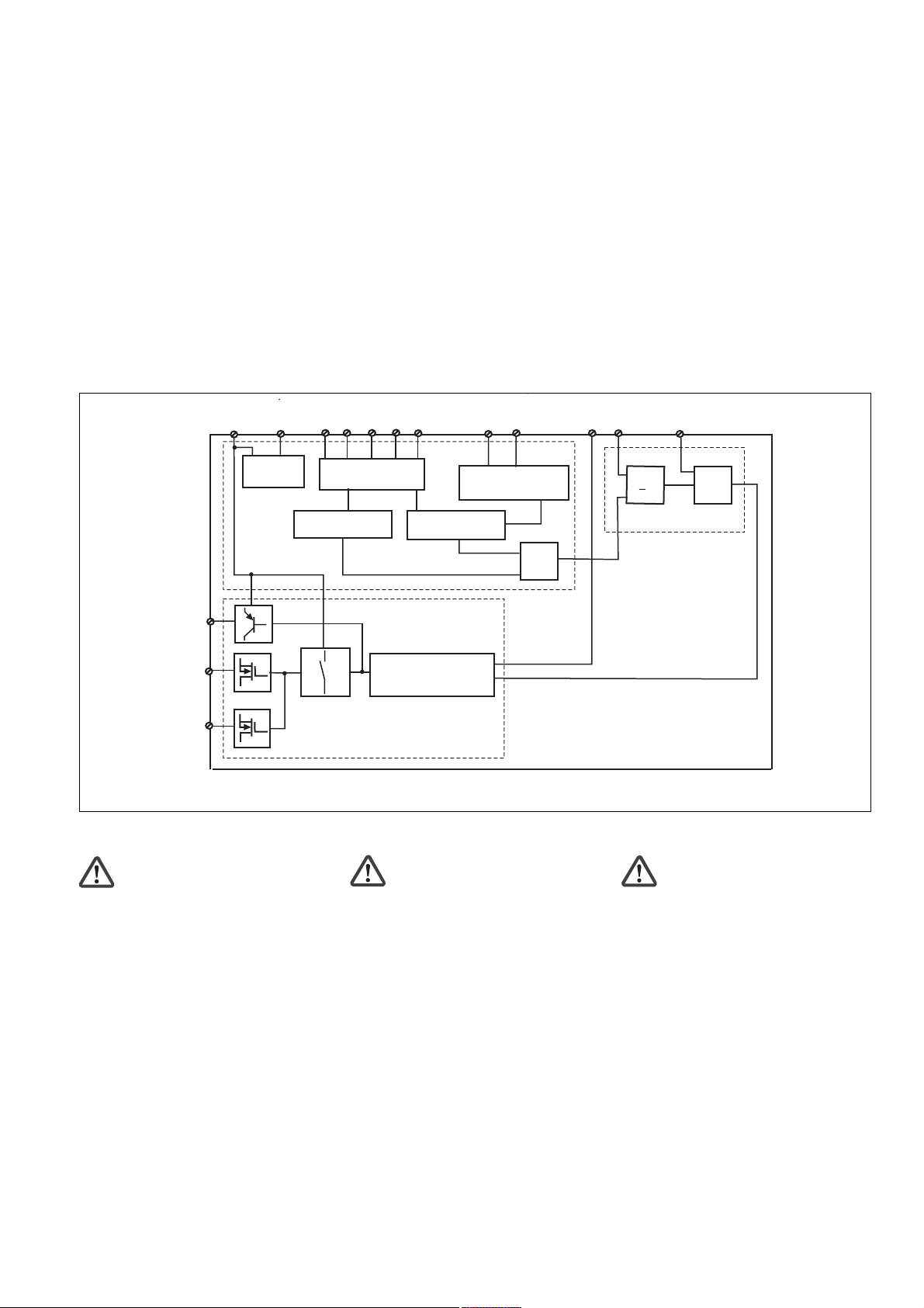
Y32
14
24
UB
A1
Netzteil/
Power unit/
Alimentation
A2
µController 1
S34
S12
S22
Eingangsschaltung/
Input circuit/
Circuit d'entrée
Rückführkreis/
Feedback control loop/
Boucle de retour
Y4
Y5
µController 2
Taktausgänge/
test pulse outputs/
Sorties impulsionnelles
Innenschaltbild Schéma interneInternal wiring diagram
Sicherheitsschaltgerät montieren
Achtung! Durch elektrostatische
Entladung können Bauteile des
Sicherheitssystems beschädigt
werden. Sorgen Sie für Entladung,
bevor Sie das Sicherheitssystem
berühren, z. B. durch Berühren einer
geerdeten, leitfähigen Fläche oder
Installing the safety relay
Caution! Electrostatic discharge can
damage components on the safety
system. Ensure against discharge
before touching the safety system,
e.g. by touching an earthed,
conductive surface or by wearing an
earthed armband.
durch Tragen eines geerdeten
Armbands.
• Install the safety relay in a control cabinet
with a protection type of at least IP54.
• Montieren Sie das Sicherheitsschaltgerät
in einen Schaltschrank mit einer Schutzart von mindestens IP54.
• Befestigen Sie das Gerät mit Hilfe des
Rastelements auf der Rückseite auf einer
• Use the notch on the rear of the unit to
attach it to a DIN rail.
• Attach the unit securely to a vertical DIN
rail (35 mm) using a fixture such as a
retaining bracket or end angle.
Normschiene.
• Sichern Sie das Gerät auf einer senkrechten Normschiene (35 mm) durch ein
Halteelement (z. B. Endhalter oder
Endwinkel)
S21
S11
S35
Y6
&
S36
>1
&
Installer le bloc logique de sécurité
Attention ! Une décharge électro-
statique peut endommager les
éléments du système de sécurité.
Veillez à vous décharger avant de
toucher le système de sécurité, par
ex. en touchant une surface
conductrice mise à la terre ou en
portant un bracelet de mise à la
terre.
• Montez le bloc logique de sécurité dans
une armoire ayant un indice de protection
d’au moins IP 54.
• Montez l’appareil sur un rail normalisé à
l’aide du système de fixation situé au dos
de l’appareil.
• Assurez la fixation de l’appareil sur un rail
normalisé vertical (35 mm) par un
élément de maintien (par ex. un élément
ou un coude terminal)
- 3 -
Page 4

Achtung!
UND-/ODER- Verknüpfung:
• Montieren Sie alle über die UND-/
ODER- Eingänge verknüpften
Geräte im gleichen Schaltschrank
oder
• Stellen Sie sicher, dass Fehler
über die Verbindung der Geräte
ausgeschlossen werden z.B.
durch geschützte Verlegung der
Verbindungsleitung.
Caution!
AND-/OR connection:
• Install all the devices that are
linked via the AND/OR inputs in
the same control cabinet
or
• make sure that faults that occur
from the connection of the
devices can be excluded, e.g. by
secure laying of connection
cables.
Attention!
Liaison ET/OU :
• Montez l'ensemble des appareils
reliés via les entrées ET/OU dans
la même armoire électrique
ou
• assurez-vous que la connexion
des appareils n'entraîne pas
d'erreurs, en protégeant, par
exemple, les câbles de
raccordement entre les appareils.
Sicherheitssystem in Betrieb
nehmen
Beachten Sie beim Einsatz der Schaltmatten:
• Die Schaltmatten lösen erst aus, wenn sie
von Personen mit einem Gewicht von
mehr als 35 kg belastet werden.
• Unzulässig sind: Gehhilfen wie z. B.
Spazierstöcke und Räderfahrzeuge
Inbetriebnahme vorbereiten
Beachten Sie bei der Vorbereitung der
Inbetriebnahme:
• Das Gerät und die Eingangskreise
müssen immer aus einem Netzteil
versorgt werden.
• Verwenden Sie Leitungsmaterial aus
Kupferdraht mit einer Temperaturbeständigkeit von 60/75°C.
• Berechnung der max. Leitungslänge I
am Eingangs-, Start und Rückführkreis:
R
I
max
R
widerstand (s. technische Daten)
lmax
=
Rl / km
= max. Gesamtleitungs-
lmax
Rl /km = Leitungswiderstand/km
• Schützen Sie Leitungen, die außerhalb
des Schaltschranks verlegt werden
müssen, vor mechanischer Beschädigung
z. B. durch die Verlegung in einem
Panzerrohr.
• Ausgang 14, 24: bei Leerlauf eine
Kapazität bis max. 2 nF ansteuerbar
• Setzen Sie die Sicherheitsausgänge 14
und 24 ausschließlich für sichere
Anwendungen ein. Die Sicherheitsausgänge dürfen nicht mit SPS-Eingängen verbunden werden.
Um die Ausschaltimpulse an den
Halbleiterausgängen 14 und 24 zu
unterdrücken, setzen Sie die Reihenklemme mit Filter Bestellnummer 774195
oder 774196 ein.
• Der Ausgang Y32 ist ein Hilfsausgang
z. B. für die Kommunikation mit einer SPS
oder einer Anzeige.
• Verwenden Sie Freilaufdioden, wenn Sie
mit den Sicherheits-/Hilfsausgängen
Schütze oder Relais ansteuern.
max
Commissioning the safety system
Please note the following when using
safety mats:
• Safety mats will only be triggered if
accessed by a person weighing more
than 35 kg.
• Not permitted: Aids such as walking sticks
and wheeled vehicles
Preparing for commissioning
Please note the following when preparing
for commissioning:
• Power for the unit and the input circuits
must always be provided from a single
power supply.
• Use copper wire that will withstand
temperatures of 60/75 °C.
• Calculating the max. cable runs I
input, reset and feedback loop:
R
I
max
R
resistance (see "Technical details")
lmax
=
Rl / km
= max. overall cable
lmax
Rl /km = Cable resistance/km
• Cables that have to be laid outside the
control cabinet must be protected from
mechanical damage, e.g. by installing
them in a conduit.
• Output 14, 24: at no-load, a capacitance
of max. 2 nF can be controlled
• Safety outputs 14 and 24 should be used
exclusively for safe applications. The
safety outputs must not be connected to
PLC inputs.
In order to suppress the pulses on switchoff on the semiconductor outputs 14 and
24, the terminal block with filter, order
number 774195 or 774196 should be
used.
• Output Y32 is an auxiliary output, e.g. for
communication with a PLC or display.
• Use flywheel diodes to drive contactors or
relays with the safety/auxiliary outputs.
max
at the
Mise en service du système de
sécurité
Tenez compte en cas d’utilisation des
tapis sensibles :
• Les tapis sensibles ne se déclenchent
que s’ils sont occupés par des personnes
d’un poids de plus de 35 kilos.
• Leur accès est interdit avec : des aides
comme des cannes de promenade ou des
véhicules à roues
Préparation de la mise en service
Points importants pour la préparation de la
mise en service :
• L’appareil et les circuits d’entrée doivent
toujours être reliés à la même source
d’alimentation.
• Utilisez uniquement des fils de câblage
en cuivre résistant à des températures de
60/75 °C.
• Calcul de la longueur de conducteur
maximum I
réarmement et sur la boucle de retour :
I
=
max
R
= résistance de câblage totale
lmax
max. (voir les caractéristiques techniques)
Rl /km = résistance des conducteurs/km
• Veuillez protéger les conducteurs qui
doivent être posés en dehors de l’armoire
électrique contre les détériorations
mécaniques, par exemple en les posant
dans un tube en acier.
• Sortie 14, 24 : en cas de fonctionnement
à vide, une capacité max. de 2 nF peut
être contrôlée.
• Utilisez les sorties de sécurité 14 et 24
uniquement dans des circuits de sécurité.
Les sorties de sécurité ne doivent pas
être raccordées à des entrées d’API.
Pour supprimer l'impulsion de coupure
aux sorties statiques 14 et 24, utilisez les
bornes avec filtre, référence 774195 ou
774196.
• La sortie Y32 est une sortie d’information
pour la communication par exemple avec
un API ou un témoin.
• Utilisez des diodes de roue libre lorsque
vous commandez des contacteurs ou des
relais au moyen des sorties de sécurité/
d’information.
sur le circuit d’entrée, de
max
R
lmax
Rl / km
- 4 -
Page 5

Betriebsbereitschaft herstellen
• Verdrahten Sie die Versorgungspannung:
Klemme A1(+) : + 24 V DC
Klemme A2(-) : 0 V
• Verdrahten Sie die Schaltmatte mit den
Eingängen und legen Sie durch die Verdrahtung von Y4 fest, ob Sie
- die UND/ODER-Eingänge des
PNOZ e4.1p verwenden
und ob
- das PNOZ e4.1p mit seinen Ausgängen
eine PSS oder ein PNOZelog-Gerät
ansteuert.
Achtung! An Ausgänge, die eine
PSS ansteuern, dürfen keine
zusätzlichen Lasten angeschlossen
werden.
Sollen ausschließlich Schütze angesteuert
werden, empfehlen wir die Verdrahtung wie
bei der Ansteuerung der PSS.
Preparing for operation
• Connect the supply voltage:
Terminal A1(+) : +24 V DC
Terminal A2(-) : 0 V
• Connect the safety mat to the inputs and
define via the wiring of Y4 whether
you are:
- using the AND/OR inputs of the
PNOZ e4.1p
and whether
- the PNOZ e4.1p is controlling a PSS
or a PNOZelog unit with its outputs.
Caution! No additional loads may be
connected to outputs that are used to
control a PSS.
If contactors alone are being controlled, we
recommend the wiring for controlling a PSS.
Mise en route
• Raccordez la tension d’alimentation :
Borne A1(+) : +24 V DC
Borne A2(-) : 0 V
• Raccordez le tapis sensible aux entrées
et déterminez à l’aide de Y4 si vous
voulez utiliser
- les entrées ET/OU du PNOZ e4.1p
et si
- le PNOZ e4.1p commande un PSS ou
un appareil PNOZelog par ses sorties.
Attention ! Les sorties qui
commandent un PSS ne doivent pas
être raccordées à d’autres charges.
S’il y a lieu de raccorder exclusivement des
relais, nous recommandons le même
raccordement que pour la commande d’un
PSS.
Eingangskreis
Input circuit
Circuit d’entrée
Ansteuerung einer PSS
Controlling a PSS
Pilotage d’un PSS
Ansteuerung eines PNOZelog-Geräts
Controlling a PNOZelog unit
Pilotage d’un appareil PNOZelog
• Stellen Sie die Rückstelleigenschaften
durch Verdrahten des Startkreises ein.
Eingangskreis
Input circuit
Circuit d’entrée
Schaltmatte ohne Anlauftest
Safety mat without start-up test
Tapis sensible sans test des conditions
initiales
UND-Verknüpfung und ODER-Verknüpfung
aktiv
AND connection and OR connection active
Fonction logique ET ou fonction logique OU
active
rot/red/rouge
S11
rot/red/rouge
Y4
A1
Y4
S12
S21
S22
S11
S12
S21
S22
schwarz/black/noir
schwarz/black
rot/red/rouge
rot/red/rouge
schwarz/black/noir
schwarz/black
/noir
/noir
• Set the reset features via the wiring of the
reset circuit.
Automatische Rückstellung (Start)
Automatic reset (start)
Réarmement automatique (Start)
S11
S34
keine Verknüpfung oder nur ODERVerknüpfung aktiv
No connection or just OR connection active
pas de fonction logique active ou seulement
la fonction logique OU
rot/red/rouge
S11
rot/red/rouge
Y4
S11
Y4
S21
S12
schwarz/black/noir
S21
S22
S11
S12
schwarz/black/noir
S21
S22
schwarz/black
rot/red/rouge
rot/red/rouge
schwarz/black
/noir
/noir
• Déterminez le type de réarmement par
câblage du circuit de réarmement
Manuelle Rückstellung (Start)
Manual reset (start)
Réarmement manuel (Start)
S3
A1
S34
Schaltmatte mit Anlauftest
Safety mat with start-up test
Tapis sensible avec test des conditions
initiales
• Schließen Sie den Rückführkreis, indem
Sie Y6-A1 brücken oder die Kontakte
externer Schütze zwischen Y6 und A1
anschließen.
Achtung! Schließen Sie nicht die
Kontakte der externen Schütze in
Reihe zum Startkreis an.
Der Rückführkreis wird überwacht. Spätestens 150 ms nach dem Ausschalten des
Ausgangs muss der Rückführkreis wieder
geschlossen sein.
S21
S34
• Close the feedback loop by linking Y6A1 or by connecting contacts from
external contactors between Y6 and A1.
Caution! Do not connect the
contacts from external contactors in
series to the reset circuit.
The feedback loop is monitored. The
feedback loop must be closed no later than
150 ms after the output has switched off.
- 5 -
• Raccordez la boucle de retour, en
pontant Y6-A1 ou en raccordant les
contacts de relais externes entre
Y6 et A1 .
Attention ! Ne raccordez pas les
contacts des relais externes en série
avec le circuit de réarmement.
La boucle de retour est surveillée. Au plus
tard 150 ms après le déclenchement de la
sortie correspondante, la boucle de retour
doit être refermée.
Page 6

Sicherheitsschaltgerät einzeln
verwenden
Bitte beachten Sie:
Wenn Sie das PNOZ e4.1p allein verwenden, verdrahten Sie wie bei der ODERVerknüpfung (siehe "Sicherheitsschaltgeräte
verknüpfen").
Sicherheitsschaltgeräte verknüpfen
Beachten Sie beim Verknüpfen mehrerer
Geräte:
• Das Verknüpfen von PNOZ e1p ist erst ab
Version 3.0 zulässig.
• Sicherheitsausgänge, an denen Lasten
angeschlossen sind, dürfen zusätzlich mit
den Sicherheitseingängen von max. 4
PNOZelog-Geräten verbunden werden.
• Sie dürfen ausschließlich Sicherheitsausgänge von PNOZelog-Geräten von
Pilz UND/ODER-verknüpfen. Das Gerät
mit der niedrigsten Kategorie bestimmt
die Kategorie nach EN 954-1 der
Gesamtschaltung.
• Alle verknüpften Geräte müssen an die
gleiche Versorgungsspannung angeschlossen werden.
Using the safety relay as a single unit
Please note:
If you are using the PNOZ e4.1p on its own,
make the OR connection (see "Linking the
units").
Connecting safety relays
When connecting several units, please note:
• The PNOZ e1p can only be linked from
version 3.0.
• Safety outputs that have loads connected
may also be connected to the safety
inputs of a max. of 4 PNOZelog units.
• Only safety outputs on Pilz PNOZelog
units may be AND/OR connected. The
unit with the lowest category determines
the category of the whole circuit in
accordance with EN 954-1.
• All connected units must be connected to
the same supply voltage.
Utilisation séparée du bloc loquique de
sécurité
Veuillez noter s.v.p. :
Si vous souhaitez utiliser le PNOZ e4.1p
séparément, câblez-le comme le couplage
OU (voir "Coupler les blocs logiques de
sécurité").
Couplage de blocs logiques de sécurité
Veuillez noter les points suivants en cas de
couplage de plusieurs appareils :
• Le couplage de PNOZ e1p n’est permis
qu’à partir de version 3.0.
• Les sorties de sécurité utilisées pour
piloter des charges peuvent être
raccordées en plus au max. à 4 entrées
de sécurité de relais de la gamme
PNOZelog.
• Seules les sorties de sécurité des relais
PNOZelog de Pilz peuvent être utilisées
pour les couplages ET/OU. Le relais de
plus petite catégorie détermine la
catégorie de l’ensemble du circuit selon
EN 954-1.
• Tous les appareils reliés doivent être
raccordés à la même tension
d’alimentation.
Eingangskreis
Input circuit
Circuit d’entrée
Ansteuerung einer PSS
Controlling a PSS
Pilotage d’un PSS
Ansteuerung eines
PNOZelog-Geräts
Controlling a PNOZelog
unit
Pilotage d’un appareil
PNOZelog
UND-/ODER-Verknüpfung
Warnung! Das Ausgangssignal
eines PNOZelog-Geräts am ODEREingang überbrückt die
Sicherheitsfunktion des Geräts. Die
Sicherheitsausgänge leiten dann
unabhängig vom Zustand der
Eingangskreise.
UND und ODER
AND and OR
ET et OU
14/24
PNOZelog
PNOZelog
PNOZelog
PNOZelog
14/24
14/24
AND
OR
AND
OR
Y4
A1
14
24
S36
S35
PNOZ e4.1p
Y4
14/24
S36
S35
PNOZ e4.1p
S36
PNOZelog
AND/OR connection
Warning! The output signal from a
PNOZelog device at the OR input will
bridge the unit’s safety function. The
safety outputs will then energise,
irrespective of the status of the input
circuits.
Input 1
Input 2
PSS
UND
AND
ET
14/24
PNOZelog
14/24
PNOZelog
AND
AND
Y4
A1
S36
PNOZ e4.1p
Y4
S36
14/24
PNOZ e4.1p
14
24
ODER
OR
OU
Input 1
Input 2
PSS
S36
PNOZelog
PNOZelog
Liaison ET/OU
Avertissement ! Le signal de sortie
d’un appareil PNOZelog sur l’entrée
OU ponte la fonction de sécurité du
relais. Les sorties de sécurité sont
alors sous tension, indépendamment
de l’état des circuits d’entrée.
14/24
PNOZelog
14/24
OR
OR
Y4
S11
14
24
S35
PNOZ e4.1p
Y4
S21
14/24
S35
PNOZ e4.1p
Input 1
Input 2
PSS
S36
PNOZelog
- 6 -
Page 7

Betrieb
Der Start des Sicherheitssystems ist nur
möglich, wenn die Schaltmatte nicht
betreten ist. Beim Start erkennt das Gerät
die eingestellte Betriebsart. In der dafür
benötigten Zeit blinkt die LED "POWER".
Das Gerät ist betriebsbereit, wenn die LED
"POWER" dauerhaft leuchtet.
Statusanzeigen
•"CH.1" bzw. "CH.2" leuchtet: Sicherheits-
ausgang 14 bzw. 24 führt High-Signal.
•"CH.1" bzw. "CH.2" erlöschen:
Sicherheitsausgang 14 bzw. 24 führt LowSignal.
Operation
The safety system can only be started if the
safety mat has not been activated. The unit
detects the operating mode set on start-up.
During this time the "POWER" LED will
flash.
The unit is ready for operation when the
"POWER" LED is lit continuously.
Status indicators
•"CH.1"/"CH.2" lights up: Safety output
14/24 is high.
•"CH.1"/"CH.2" extinguishes: Safety
output
14/24 is low.
Fonctionnement
Le réarmement du système de sécurité
n’est possible que si le tapis sensible n’est
pas occupé. Au démarrage, l’appareil
identifie le mode de fonctionnement défini.
Pendant la durée nécessaire à cette
détection, la LED " POWER " clignote.
L’appareil est prêt à fonctionner lorsque la
" LED POWER " reste allumée.
Affichages d’état
•" CH.1 " ou " CH.2 " s’allume : la sortie de
sécurité 14 ou 24 présente un signal
Haut.
•" CH.1" ou " CH.2 " s’éteignent : la sortie
de sécurité 14 ou 24 présente un signal
Bas.
Fehler - Störungen
Fehleranzeige
• LED "CH.1" oder LED "CH.2" blinkt:
Interner Fehler, Verdrahtungsfehler oder
Querschluss
• "CH.1" und "CH.2" blinken abwechselnd:
- Rückführkreis beim Start offen
Abhilfe: Rückführkreis schließen, LowSignal am ODER-Eingang anlegen,
Schaltmatte betreten und wieder
verlassen.
Gerät wieder starten
Wenn Sie den Fehler behoben haben,
starten Sie das Gerät neu, indem Sie es
kurz von der Spannungsversorgung trennen
und wieder anschließen.
Zur eingehenden Fehlerbehandlung
benutzen Sie bitte den Technischen Katalog
PNOZelog.
Faults
Fault indicator
• LED "CH.1" or LED "CH.2" flashes:
Internal error, wiring error or short across
contacts
• "CH.1" and "CH.2" flash alternately:
- Feedback loop open on start-up
Remedy: Close feedback loop, apply a
low signal at the OR input, activate the
safety mat and then clear it.
To restart the unit
Once you have rectified the fault, restart the
unit by briefly switching off the power supply
and switching it back on.
Please consult the PNOZelog technical
catalogue for detailed troubleshooting.
Erreurs - Defaillances
Affichage des erreurs
• La LED " CH.1 " ou la LED " CH.2 "
clignote :
défaut interne, erreur de câblage ou
court-circuit
• " CH.1" et " CH.2 " clignotent en
alternance :
- La boucle de retour est ouverte lors du
réarmement
Remède : fermez les circuits de retour,
appliquer un signal Bas à l’entrée OU,
occuper, puis libérer le tapis sensible.
Redémarrer l’appareil
Une fois l’erreur supprimée, redémarrez
l’appareil en coupant brèvement
l’alimentation en tension puis en la
réactivant.
Pour des informations plus détaillées
concernant le traitement des erreurs,
veuillez vous référer au Catalogue
technique PNOZelog.
- 7 -
Page 8

DD
D
DD
Anschlussbeispiel:
UND-Verknüpfung von
3 PNOZelog-Geräten, Unit 3:
automatische Rückstellung, ohne
Anlauftest
L+
S1
GBGB
GB
GBGB
Connection example:
AND connection of
3 PNOZelog units, unit 3:
automatic reset, without
start-up test
S2
K3
K5
FF
F
Exemple de raccordement :
FF
Couplage logique ET de
3 blocs PNOZelog, unité 3 :
réarmement automatique, sans
test des conditions initiales
K1
K2
A1
S11
S34Y4
S12Y6S22
A1
Unit 1 Unit 2 Unit 3
PNOZ e1p
A2
14
K1
L-
S22
S21
K2
Y32S12
Y524
PNOZ e1vp
A2
14
K3
Steckbare Klemmen abziehen
Schraubendreher in Gehäuseaussparung
hinter der Klemme ansetzen und Klemme
heraushebeln.
Klemmen nicht an den Kabeln abziehen!
S11
S36
S21
K4
S34Y4
Y32S35
K4
Y7
Y524
K5
K6
S12Y6S22
A1
PNOZ e4.1p
A2
14
S11
S36
S21
K6
S34Y4
Y32S35
Y524
Remove plug-in terminals
Insert screwdriver into the cut-out of the
housing behind the terminal and lever the
terminal.
Do not remove the terminals by pulling the
cables!
Unit 1
Unit 2
14
&
S36
Unit 3
S36
24
Démonter les borniers débrochables
Placer un tournevis derrière les bornes et
sortir le bornier.
Ne pas retirer les borniers en tirant sur les
câbles !
24
&
Abziehen der Klemmen am Beispiel einer
Schraubklemme
How to remove the terminals using a screw
terminal as an example
- 8 -
Démontage d’un bornier à vis
Page 9

Technische Daten
Technical details
Caractéristiques techniques
Elektrische Daten
Versorgungsspannung U
Spannungstoleranz U
Leistungsaufnahme bei U
ohne Last
Restwelligkeit U
B
B
B
B
Ausgänge, Halbleiter
Sicherheitsausgänge (S)
Hilfsausgang (S)
Schaltvermögen, Halbleiter
2 Ausgänge belastet
1 Ausgang belastet
Gesamtleistung, ext. Last,
Halbleiter
Spannung und Strom an
Eingangskreis, Startkreis,
Rückführkreis
Hilfsausgang, Taktausgänge
UND/ODER-Eingänge
Geräteabsicherung
Max. Gesamtleitungswiderstand
R
Start- und Rückführkreis
lmax
Max. Gesamtleitungswiderstand
R
Eingangskreis
lmax
Max. Schaltmattenwiderstand
Sicherheitstechnische Kenndaten
PL nach EN ISO 13849-1
Kaskadiereingang
HL-Ausgang
Kategorie nach EN 954-1
Kaskadiereingang
HL-Ausgang
SIL CL nach EN IEC 62061
Kaskadiereingang
HL-Ausgang
PFH nach EN IEC 62061
Kaskadiereingang
HL-Ausgang
SIL nach IEC 61511
Kaskadiereingang
HL-Ausgang
PFD nach IEC 61511
Kaskadiereingang
HL-Ausgang
tM in Jahren
Zeiten
Einschaltverzögerung
Überwachter Start
Automatischer Start
Ansprechzeit (Rückfallverzögerung)
bei Not-Halt, an S35/S36
unverzögerte Sicherheitsausgänge
Einschaltverzögerung (bei erstem
Start nach Anlegen von UB)
Einschaltverzögerung an S35/S36
Max. Zeit der
Rückführkreisüberwachung
Electrical data
Supply voltage U
Voltage tolerance U
Power consumption at U
without load
Residual ripple U
B
B
B
B
Semiconductor outputs
Safety outputs (N/O)
Auxiliary output (N/O)
Switching capability,
semiconductor outputs
2 outputs under load
1 output under load
total power, ext. load,
semicondustor outputs
Voltage and current at
Input circuit, reset circuit,
Feedback loop
Auxiliary output, test pulse outputs
AND/OR inputs
Unit fuse protection
Max. overall cable resistance
R
reset and feedback circuit
lmax
Max. overall cable resistance
R
input circuit
lmax
Max. safety mat resistance
Safety-related characteristic
data
PL in accordance with
EN ISO 13849-1
Cascading input
SC output
Category in accordance with
EN 954-1
Cascading input
SC output
SIL CL in accordance with
EN IEC 62061
Cascading input
SC output
PFH in accordance with
EN IEC 62061
Cascading input
SC output
SIL in accordance with IEC 61511
Cascading input
SC output
PFD in accordance with IEC 61511
Cascading input
SC output
tM in years
Times
Delay-on energisation
Monitored reset
Automatic reset
Reaction time (delay-on deenergisation) on E-STOP, at S35/S36
Instantaneous safety outputs
Switch-on delay (at the first
reset after applying UB)
Switch-on delay at S35/S36
Max. time of feedback loop
monitoring
Données électriques
Tension d’alimentation U
Plage de la tension d’alimentation U
Consommation pour U
sans charge
Ondulation résiduelle U
B
B
B
B
Sorties statiqies
Sorties de sécurité (S)
Sortie d’information (S)
Caractéristiques de commutation,
sorties statiques
2 sorties chargées
1 sortie chargée
Puissance total, charge ext.,
sorties statiques
Tension et courant au
Circuit d’entrée, circuit de réarmement,
boucle de retour
Sortie d’information, sorties
impulsionnelles
Entrées ET/OU
Protection du relais
Résistance de câblage totale max.
R
circuit de réarmement et boucle
lmax
Résistance de câblage totale max.
R
circuit d’entrée
lmax
Résistance maximale du tapis sensible
Caractéristiques techniques de
sécurité
PL selon EN ISO 13849-1
Entrée en cascade
Sortie HL
Catégorie selin EN 954-1
Entrée en cascade
Sortie HL
SIL CL selon EN IEC 62061
Entrée en cascade
Sortie HL
PFH selon EN IEC 62061
Entrée en cascade
Sortie HL
SIL selon IEC 61511
Entrée en cascade
Sortie HL
PFD selon IEC 61511
Entrée en cascade
Sortie HL
tM en années
Temps
Temps de réarmement
Réarmement auto-contrôlé
Réarmement automatique
Délai d’enclenchement (retard à la retombée) en cas d’AU, sur S35/S36
Sorties de sécurité non temporisées
Temporisation d’enclenchement (au
premier démarrage après application
de UB)
Temporisation d’enclenchement
sur S35/S36
Temps max. de la surveillance de
la boucle de retour
24 V DC
80...125%
2 W
DC: 20%
2
1
UB ≤ 26,5 V: 2,0 A/50W
UB > 26,5 V: 1,5 A/45W
UB ≤ 26,5 V: 2,7 A/70W
UB > 26,5 V: 2,2 A/65W
130 W
24 V DC/ 5 mA
24 V DC/ 0,5 A
24 V DC/ 5 mA
max. 10 A flink/quick/rapide
oder/or/ou
max. 6 A träge/slow acting/
normal
2 kOhm
150 Ohm
150 Ohm
PL e (Cat. 4)
PL d (Cat. 3)
Cat. 4
Cat. 3
SIL CL 3
SIL CL 2
2,86E-10
3,68E-09
SIL 3
SIL 2
1,48E-05
6,29E-05
20
max. 260 ms, typ. 180 ms
max. 180 ms, typ. 50 ms
max. 43 ms, typ. 40 ms
3 s
max. 210 ms, typ. 60 ms
150 ms
- 9 -
Page 10

Umweltdaten
EMV
Schwingungen nach
Frequenz
Amplitude
Klimabeanspruchung
Luft- und Kriechstrecken nach
EN 60947-1
Verschmutzungsgrad
Überspannungskategorie
Umgebungstemperatur
Lagertemperatur
Schutzart
Einbauraum (z. B. Schaltschrank)
Gehäuse
Klemmenbereich
Mechanische Daten
Querschnitt des Außenleiters
(Schraubklemmen)
1 Leiter, flexibel
2 Leiter gleichen Querschnitts
flexibel mit Aderendhülse ohne
Kunststoffhülse
flexibel ohne Aderendhülse oder
mit TWIN-Aderendhülse
Querschnitt des Außenleiters
(Federkraftklemmen)
flexibel ohne Aderendhülsen
Gehäuse mit Federkraftklemmen
Abisolierlänge
Klemmstellen pro Anschluss
Anzugsdrehmoment für
Schraubklemmen
Gehäusematerial
Front
Gehäuse
Abmessungen (Schraubklemmen)
H x B x T
Abmessungen (Federkraftklemmen)
H x B x T
Gewicht
Environmental data
EMC
Vibration to
Frequency
Amplitude
Climatic suitability
Airgap creepage in accordance
with EN 60947-1
Pollution degree
Overvoltage category
Ambient temperature
Storage temperature
Protection type
Mounting (e.g. control cabinet)
Housing
Terminals
Mechanical data
Cable cross section (screw
terminals)
1 core, flexible
2 core, same cross section
flexible with crimp connectors,
without insulating sleeve
flexible without crimp connectors
or with TWIN crimp connectors
Cable cross section (spring-loaded
terminals)
flexible without crimp connectors
Housing with spring-loaded terminals
Stripping length
Terminal blocks per connection
Torque setting for screw terminals
Housing material
front panel
housing
Dimensions (screw terminals)
H x W x D
Dimensions (spring-loaded terminals)
H x W x D
Weight
Environnement
CEM
Vibrations selon
Fréquence
Amplitude
Sollicitation climatique
Cheminement et claquage selon
EN 60947-1
Niveau d'encrassement
Catégorie de surtension
Température d’utilisation
Température de stockage
Indice de protection
Lieu d’implantation (p. ex. armoire)
Boîtier
Borniers
Données mécaniques
Capacité de raccordement
(borniers à vis)
1 conducteur, souple
2 câbles de même diamètre
souple avec embout sans
chapeau plastique
souple sans embout ou avec
embout TWIN
Capacité de raccordement (borniers
à ressort)
souple sans embout
Boîtier avec borniers à ressort
Longueur de dénudage
bornes par raccordement
Couple de serrage (borniers à vis)
Matériau du boîtier
face avant
boîtier
Dimensions (borniers à vis)
H x L x P
Dimensions (borniers à ressort)
H x L x P
Poids
EN 60947-5-1, EN 610006-2, EN 61000-6-4
EN 60068-2-6
10...55 Hz
0,35 mm
EN 60068-2-78
2
III
-10...+55 °C
-25...+70 °C
IP54
IP40
IP20
0,25 ... 2,5 mm2/24-12 AWG
0,25 ... 1 mm2/24-16 AWG
0,20 ... 1,5 mm2/
0,20 ... 1,5 mm2/24-16 AWG
8 mm
2
0,5 Nm
ABS UL 94 V0
PPO UL 94 V0
94 x 22,5 x 121 mm
101 x 22,5 x 121 mm
135 g
24-16 AWG
Es gelten die 2005-08 aktuellen Ausgaben
der Normen.
The version of the standards current at
2005-08 apply.
Se référer à la version des normes en
vigeur au 2005-08.
- 10 -
Page 11

4GB Dimensions in mm (") 4F Dimensions en mm (")4D Abmessungen in mm (")
Gehäuse mit steckbaren Schraubklemmen/
Housing with plug-in screw terminals/
Boîtier avec borniers débrochables à vis
75 (2.95")
87 (3.42")
94 (3.70")
121 (4.76")
4GB Connector pin assignment 4F Affectation des raccords4D Anschlussbelegung
22,5
(0.88")
Gehäuse mit steckbaren Federkraftklemmen/
Housing with plug-in spring-loaded terminals/
Boîtier avec borniers débrochables à ressort
121 (4.76")
75 (2.95")
87 (3.42")
101 (3.98")
22,5
(0.88")
EG-Konformitätserklärung:
Diese(s) Produkt(e) erfüllen die Anforderungen der Richtlinie 2006/42/EG über
Maschinen des europäischen Parlaments
und des Rates.
Die vollständige EG-Konformitätserklärung
finden Sie im Internet unter www.pilz.com
Bevollmächtigter: Norbert Fröhlich,
Pilz GmbH & Co. KG, Felix-Wankel-Str. 2,
73760 Ostfildern, Deutschland
1
2
3
EC Declaration of Conformity:
This (these) product(s) comply with the
requirements of Directive 2006/42/EC of the
European Parliament and of the Council on
machinery.
The complete EC Declaration of Conformity
is available on the Internet at www.pilz.com
Authorised representative: Norbert Fröhlich,
Pilz GmbH & Co. KG, Felix-Wankel-Str. 2,
73760 Ostfildern, Germany
Déclaration de conformité CE :
Ce(s) produit(s) satisfait (satisfont) aux
exigences de la directive 2006/42/CE
relative aux machines du Parlement
Européen et du Conseil.
Vous trouverez la déclaration de conformité
CE complète sur notre site internet
www.pilz.com
Représentant : Norbert Fröhlich,
Pilz GmbH & Co. KG, Felix-Wankel-Str. 2,
73760 Ostfildern, Allemagne
- 11 -
Page 12

Notizen
Notes
Notes
Technischer Support
+49 711 3409-444 +49 711 3409-444
...
In vielen Ländern sind wir durch
unsere Tochtergesellschaften und
Handelspartner vertreten.
Nähere Informationen entnehmen
Sie bitte unserer Homepage oder
nehmen Sie Kontakt mit unserem
Stammhaus auf.
Technical support
... ...
In many countries we are
represented by our subsidiaries
and sales partners.
Please refer to our Homepage
for further details or contact our
headquarters.
Assistance technique
+49 711 3409-444
Nos filiales et partenaires
commerciaux nous représentent
dans plusieurs pays.
Pour plus de renseignements,
consultez notre site internet ou
contactez notre maison mère.
- 12 -
www
www.pilz.com
Pilz GmbH & Co. KG
Felix-Wankel-Straße 2
73760 Ostfildern, Germany
Telephone: +49 711 3409-0
Telefax: +49 711 3409-133
E-Mail: pilz.gmbh@pilz.de
Originalbetriebsanleitung/Original instructions/Notice originale
21362-3FR-03, 2010-05 Printed in Germany
 Loading...