

Page 1

21386-3FR-04
PNOZ e2.1p
4
D Betriebsanleitung
4
GB Operating instructions
4
F Manuel d'utilisation
Zweihandbediengerät PNOZ e2.1p
Das Gerät erfüllt die Anforderung nach
EN 574, Typ III C.
Das Zweihandbediengerät zwingt den
Bediener einer Presse, zur Vermeidung von
Handverletzungen die Hände während der
gefahrbringenden Schließbewegung
außerhalb der Gefahrenstelle zu halten.
Das Gerät ist zum Einbau in Steuerungen
für Pressen der Metallbearbeitung als
Baustein der Gleichzeitigkeit geeignet.
Es kann als Handschutzeinrichtung
eingesetzt werden nach den technischen
Regeln
• Exzenter- und verwandte Pressen
(EN 692)
• hydraulische Pressen (EN 693)
• Spindelpressen (EN 692)
oder in
• Sicherheitsstromkreisen nach EN 602041 (VDE 0113-1)
Wichtige Daten für Projektierung und
Anwendung finden Sie auch im technischen
Katalog PNOZelog.
Zu Ihrer Sicherheit
Das Zweihandbediengerät erfüllt alle
notwendigen Bedingungen für einen
sicheren Betrieb.
Beachten Sie jedoch nachfolgend aufgeführte Sicherheitsbestimmungen:
• Installieren und nehmen Sie das Gerät
nur dann in Betrieb, wenn Sie diese
Betriebsanleitung gelesen und verstanden haben und Sie mit und den geltenden
Vorschriften über Arbeitssicherheit und
Unfallverhütung vertraut sind.
• Verwenden Sie das Gerät nur gemäß
seiner Bestimmung. Beachten Sie dazu
auch die Werte im Abschnitt "Technische
Daten".
• Halten Sie beim Transport, bei der
Lagerung und im Betrieb die Bedingungen ein, wie sie unter "Technische Daten"
angegeben sind.
• Die Zweihandschaltung und die vor- und
nachgeschalteten Teile der Pressensteuerung müssen den einschlägigen VDEBestimmungen und den Sicherheitsregeln
EN 574, EN 692 und EN 693 entsprechen.
• Öffnen Sie nicht das Gehäuse und
nehmen Sie auch keine eigenmächtigen
Umbauten vor.
• Schalten Sie bei Wartungsarbeiten (z. B.
beim Austausch von Schützen) unbedingt
die Versorgungsspannung ab oder öffnen
Sie die Eingangskreise, sonst kann das
Gerät bei Verdrahtungsfehlern unerwartet
einschalten.
Two-hand relay PNOZ e2.1p
The unit fulfils the requirements to EN 574,
type III C.
The two-hand relay can be used to enable a
machine operator to avoid hand injury as
the hands are kept out of the hazardous
area during the dangerous machine closing
movement.
The unit is suitable for use in controlling
metalworking presses for simultaneous
switching.
It can be used as a hand protection device
according to the technical safety
requirements:
• Eccentric and related presses
(EN 692)
• Hydraulic presses (EN 693)
• Fly presses (EN 692)
or in
• Safety circuits according to EN 60204-1
(VDE 0113-1)
Important data for project planning and
application can also be found in the
PNOZelog technical catalogue.
For your safety
The two-hand relay meets all necessary
conditions for safe operation.
However, please note the following safety
regulations:
• Only install and commission the unit if you
have read and understood these
instructions and are familiar with both
these instructions and the current
regulations for health and safety at work
and accident prevention.
• Only use the unit in accordance with its
intended purpose. Please also take note
of the values in the "Technical details"
section.
• Transport, storage and operating
conditions should all conform to the
standards as stated under “Technical
details”.
• The two-hand circuit and the connected
parts of the press control must conform to
the relevant VDE regulations and the
safety standards EN 574, EN 692 and
EN 693.
• Do not open the housing or undertake any
unauthorised modifications.
• Please make sure you shut down the
supply voltage, or open the input circuits
when performing maintenance work
(e.g. when replacing contactors),
otherwise the device might switch on
unexpectedly in the case of a wiring error.
Relais de commande bimanuelle
PNOZ e2.1p
Le relais répond aux exigences de la norme
EN 574, Typ III C.
Les commandes bimanuelles sont des
dispositifs qui obligent les opérateurs d’une
presse à avoir les deux mains situées en
dehors de la zone à risques durant la phase
dangereuse de la fermeture afin d’éviter
toute blessure aux mains. Le relais est
spécialement adapté pour assurer la
fonction de synchronisme dans les
commandes de presse pour le travail des
métaux.
Il peut être mis en œuvre comme dispositif
de protection pour les mains conformément
aux directives techniques pour :
• les presses excentriques et apparentées
(EN 692) ;
•
les presses hydrauliques (EN 693) ;
• les presses linéaires (EN 692)
ou dans
• les circuits de sécurité d’après la norme
EN 60204-1 (VDE 0113-1).
Vous trouverez également des données
importantes pour la configuration projet et
l’utilisation dans le Catalogue technique
PNOZelog.
Pour votre sécurité
Le relais de commande bimanuelle satisfait
à toutes les conditions nécessaires pour un
fonctionnement sûr.
Toutefois, vous êtes tenu de respecter les
prescriptions de sécurité suivantes :
• Vous n’installerez l’appareil et ne le
mettrez en service qu’après avoir lu et
compris le présent manuel d’utilisation et
que si vous êtes familier avec les
prescriptions en vigueur sur la sécurité du
travail et la prévention d’accidents.
• N’utilisez l’appareil que conformément à
l’usage auquel est destiné. À ce sujet,
respectez les valeurs indiquées dans les
" Caractéristiques techniques ".
• Pour le transport, le stockage et
l'utilisation, respectez les exigences des
normes specifiées (voir „Caractéristiques
techniques“).
• Le circuit de la commande bimanuelle
ainsi que des composants amont et aval
de la commande de la presse doivent
répondre aux prescriptions en vigueur du
VDE et aux règles de sécurité EN 574,
EN 692 et EN 693.
• N’ouvrez pas le boîtier et n’effectuez pas
de modifications non autorisées.
• En cas de travaux de maintenance (par
ex. remplacement des contacteurs),
coupez impérativement la tension d’alimentation ou ouvrez les circuits d’entrée,
sinon un réarmement inopiné du relais est
possible en cas d’erreur de câblage.
- 1 -
Page 2
Beachten Sie unbedingt die Warnhinweise
in den anderen Abschnitten dieser Anleitung. Diese Hinweise sind optisch durch
Symbole hervorgehoben.
Wichtig: Beachten Sie die Sicherheitsbestimmungen, sonst erlischt
jegliche Gewährleistung.
You must take note of the warnings given in
other sections of these operating
instructions. These are highlighted visually
through the use of symbols.
Notice: Failure to keep to these
safety regulations will render the
warranty invalid.
Respectez impérativement les avertissements dans les autres paragraphes du
présent manuel d’utilisation. Ces avertissements sont signalés par des symboles
visuels.
Important : respectez les consignes
de sécurité, sinon la garantie devient
caduque.
Gerätebeschreibung
Sicherheitseigenschaften
Das Zweihandbediengerät erfüllt folgende
Sicherheitsanforderungen:
• Die Schaltung ist redundant mit Selbstüberwachung aufgebaut.
• Die Sicherheitseinrichtung bleibt auch bei
Ausfall eines Bauteils wirksam.
• Die Sicherheitsausgänge werden durch
einen Abschalttest periodisch geprüft.
• Das Gerät besitzt eine elektronische
Sicherung.
Gerätemerkmale
• Ausgänge in Halbleitertechnik:
2 Sicherheitsausgänge, 1 Hilfsausgang
und 2 Taktausgänge
• Hilfsausgang umschaltbar als Diagnoseausgang
• UND- und ODER-Eingang zur logischen
Verknüpfung mehrerer Geräte
• Querschlussüberwachung durch Taktausgänge
• Statusanzeige
• Rückführkreis zur Überwachung externer
Schütze
U
A1
B
A2
S12
Unit Description
Safety features
The two-hand relay fulfils the following
safety requirements:
• The circuit is redundant with built-in selfmonitoring.
• The safety function remains effective
even in the case of a component failure.
• The safety outputs are tested periodically
using a disconnection test.
• The unit has an electronic fuse.
Unit features
• Outputs use semiconductor technology:
2 safety outputs, 1 auxiliary output and
2 test pulse outputs
• Auxiliary output can be used as a
diagnostic output
• AND/OR input for logic links between
several units
• Test pulse outputs monitor shorts across
the input contacts
• Status display
• Feedback loop for monitoring external
contactors
S21
S22S13 Y5
S23
S11
Y6
Y7
Description de l’appareil
Propriétés de sécurité
Le relais de commande bimanuelle satisfait
aux exigences de sécurité suivantes :
• Conception redondante avec
autosurveillance.
•
Le dispositif de sécurité reste actif, même
en cas de défaillance d’un composant.
• Les sorties de sécurité sont testées
périodiquement à l’aide d’un test de
coupure.
• L’appareil est équipé d’un fusible
électronique.
Caractéristiques de l’appareil
• Sorties statiques :
2 sorties de sécurité, 1 sortie
d’information et 2 sorties impulsionnelles
• Sortie d’information commutable en sortie
de diagnostic
• Entrées ET et OU pour le couplage
logique de plusieurs appareils
• Surveillance des courts-circuits par
sorties impulsionnelles
• Affichage de l'état
• Boucle de retour pour le contrôle des
contacteurs externes
S35
S36
Netzteil/
Power unit/
Alimentation
Y32
14
24
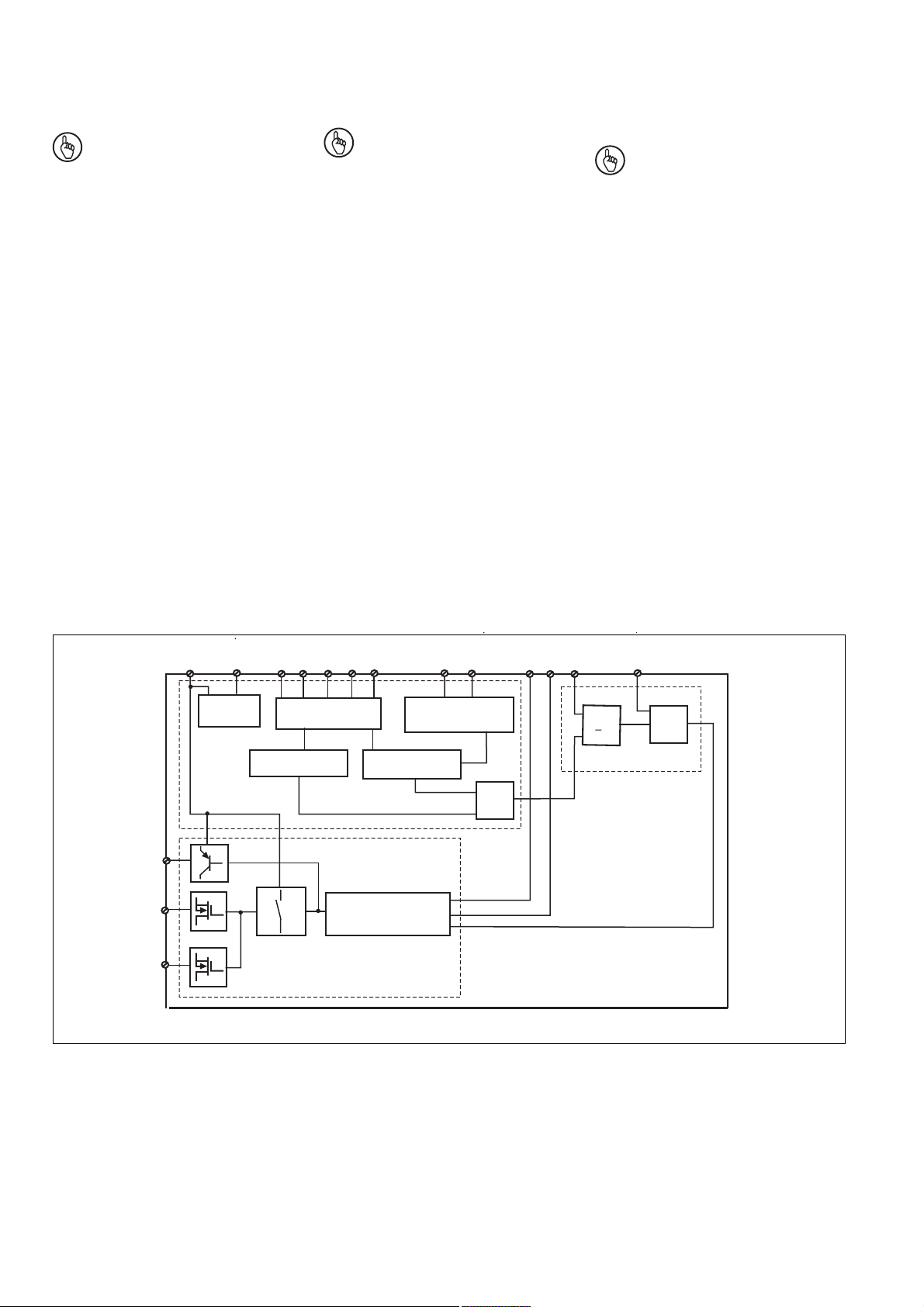
Innenschaltbild Schéma interne
Eingangsschaltung/
Input circuit/
Circuit d'entrée
µController 1
Internal wiring diagram
Taktausgänge/
test pulse outputs/
Sorties impulsionnelles
µController 2
Rückführkreis/
Feedback control loop/
Boucle de retour
>1
&
&
- 2 -
Page 3
Funktionsbeschreibung
Arbeitsweise
Das Zweihandbediengerät muss durch
gleichzeitiges Betätigen von zwei Tastern
aktiviert werden. Es unterbricht bei Loslassen eines oder beider Taster den Steuerbefehl zum Schließen der Presse. Die
Schließbewegung kann erst wieder
eingeleitet werden, nachdem beide Taster in
ihre Ausgangslage zurückgekehrt (losgelassen) sind und erneut betätigt wurden.
• Werden die beiden Taster "gleichzeitig",
d. h. innerhalb von 0,5 s betätigt, führen
die Sicherheitsausgänge 14 und 24 und
der Hilfsausgang Y32 High-Signale. Die
LED "CH.1" und "CH.2" leuchten.
• Die Sicherheitsausgänge und der
Hilfsausgang führen Low-Signal, wenn
- nur ein Bedienelement betätigt wird,
- die Gleichzeitigkeit überschritten wird,
- der Rückführkreis noch offen ist.
• Wird nach gleichzeitigem Betätigen ein
Bedienelement losgelassen, führen die
Sicherheitsausgänge und der Hilfsausgang Low-Signal. Die LED "CH.1" bzw.
"CH.2" ist aus.
• Wieder aktivieren: Die Ausgänge führen
erst wieder High-Signal, wenn beide
Bedienelemente losgelassen und erneut
gleichzeitig betätigt werden.
Function Description
Operation
The two-hand control relay must be
activated by simultaneously pressing two
buttons. If one or both of the buttons are
released, the unit interrupts the control
command to close the press. The closing
movement can only be restarted when both
buttons have returned to their start position
(released) and are pressed again.
If buttons 1 and 2 are pressed
•
"
simultaneously", i.e. within 0.5 s,
there is a High signal at the safety outputs
14 and 24 and the auxiliary output Y32.
The LEDs "CH.1" and "CH.2" illuminate.
• There is a Low signal at the safety
outputs and the auxiliary output, if:
- Only one button is pressed,
- simultaneity is not upheld,
- the feedback loop was not closed.
• If one button is released after
simultaneously pressing both buttons,
there is a Low signal at the safety outputs
and the auxiliary output. The LED "CH.1"
or "CH.2" is off.
• Reactivation: A High signal is only
present at the outputs again when both
buttons are released and pressed
simultaneously again.
Descriptif du fonctionnement
Fonctionnement
Le relais de commande bimanuelle est
activé par une action simultanée sur 2
boutons poussoirs. Il interrompt l’ordre de
commande de fermeture de la presse
lorsqu’au moins l’un des deux boutons est
relâché. Le mouvement de fermeture peut
uniquement être relancé lorsque les deux
boutons sont revenus à leur position initiale
(relâchés) et puis actionnés de nouveau.
• Si les boutons poussoirs sont actionnés
" simultanément ", c.-à-d. dans un
intervalle inférieur à 0,5 s, les sorties de
sécurité 14 et 24 et la sortie d’information
Y32 présentent un signal haut. Les LED
" CH.1 " et " CH.2 " s’allument.
•
Les sorties de sécurité et la sortie
d’information présentent un signal bas
lorsque :
- un seul bouton poussoir est actionné,
-
la plage de synchronisme est dépassée,
- la boucle de retour n’est pas fermée.
• Si, après une commande simultanée, un
des boutons poussoirs est relâché, les
sorties de sécurité et la sortie
d’information présentent un signal bas. La
LED " CH.1 " ou " CH.2 " est éteinte.
•
Réactivation : les sorties ne représentent
un signal haut que lorsque les deux boutons poussoirs ont été relâchés et ensuite
actionnés de nouveau simultanément.
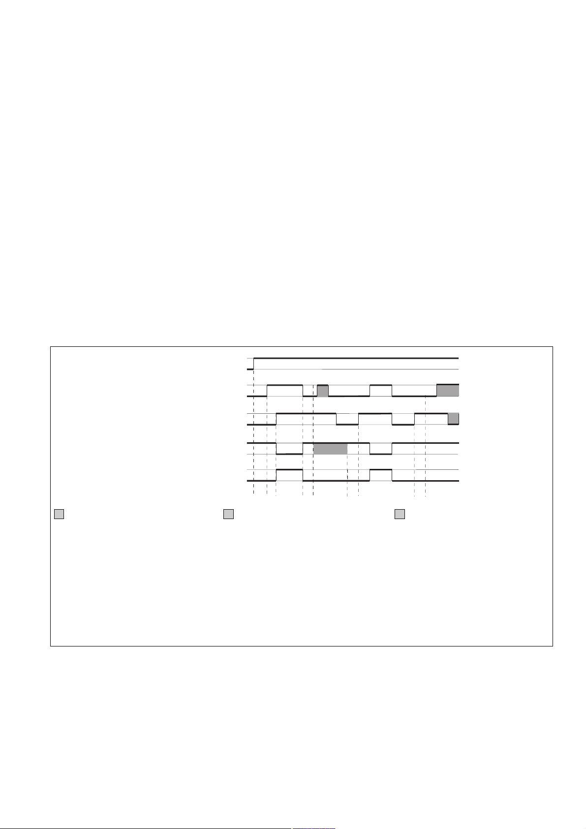
Versorgungsspannung/Supply
voltage/Tension d’alimentation
Taster 1/Button 1/Bouton
poussoir 1
Taster 2/Button 2/Bouton
poussoir 2
Rückführkreis/Feedback loop/
Boucle de retour
Ausgang/Output/Sortie
ohne Bedeutung
Rückführkreis offen: 0
Rückführkreis geschlossen: 1
t0: UB muss mind. 3 s vor Betätigen des
Tasters 1 anliegen
t1: Gleichzeitigkeit < 0,5 s
t2: Arbeitszyklus wird durch Taster 1 oder 2
beendet
t3: Y6 und Y7 müssen 150 ms nach Beenden des Arbeitszyklus geschlossen sein
t4: Y6 und Y7 müssen mind. 50 ms vor
Tasterbetätigung geschlossen sein
1
0
1
0
10101
0
1
0
1
1
0
0
t
0t1
t
t
3
2
t
4
not relevant
Feedback loop open: 0
Feedback loop closed: 1
t0: UB must be supplied at least 3 s before
button 1 is pressed
t1: Simultaneity < 0.5 s
t2: Operation cycle ended by either button 1
or button 2
t3: Y6 and Y7 must be closed for 150 ms
after the end of the operation cycle
t4: Y6 and Y7 must be closed for at least
50 ms before button is pressed
t
1
sans signification
Boucle de retour ouverte : 0
Boucle de retour fermée : 1
t0 : UB doit être présent au moins 3 s avant
l’actionnement du bouton poussoir 1.
t1 : synchronisme < 0,5 s
t2 : le cycle de travail est interrompu par le
bouton poussoir 1 ou 2.
t3 : Y6 et Y7 doivent être fermés 150 ms
après la fin du cycle de travail.
t4 : Y6 et Y7 dovent être fermés au minimum
50 ms avant l’actionnement des boutons
poussoirs.
Funktionen
• Wird an den Eingang Y5 für mindestens
250 ms ein High-Signal (+24 V DC)
gelegt, wechselt der Ausgang Y32 in die
Diagnosefunktion. Die Ansteuerung
erfolgt über einen Treiber, der als
Zubehör zur Verfügung steht oder selbst
erstellt werden kann. Ist der Eingang Y5
offen oder Low, funktioniert Y32 wie ein
Hilfsausgang.
Functions
• If there is a High signal (+24 V DC) at
input Y5 for at least 250 ms, output Y32
switches to diagnostic mode. It is
controlled via a driver that is available as
an accessory or that you can create
yourself. If input Y5 is open or low, Y32
will operate as an auxiliary output.
- 3 -
Fonctions
•
Si un signal Haut (+24 V CC) est appliqué
sur l’entrée Y5 pendant au moins 250 ms,
la sortie Y32 commute en sortie
diagnostic. La commande s’effectue par
le biais d’un protocole, disponible en tant
qu’accessoire ou programmable par
l'utilisateur. Si l’entrée Y5 est ouverte ou
en niveau Bas, Y32 fonctionne comme
une sortie d’information.
Page 4
• Zur logischen Verknüpfung mehrerer
Geräte besitzt das PNOZ e2.1p einen
UND- und einen ODER-Eingang. Die
Eingänge weisen Schaltverzögerungen
auf, die sich im Falle einer UND-/ODERVerknüpfung addieren.
• For logic links between several units, the
PNOZ e2.1p has one AND and one OR
input. The inputs have a time delay,
which is added in case of an AND/OR
connection.
• Pour le couplage logique de plusieurs
appareils, le PNOZ e2.1p possède une
entrée ET et une entrée OU. Les
entrées ont une temporisation de
couplage qui est cumulative dans le cas
d’une liaison ET/OU.
Zweihandbediengerät montieren
Achtung! Durch elektrostatische
Entladung können Bauteile des
Sicherheitssystems beschädigt
werden. Sorgen Sie für Entladung,
bevor Sie das Sicherheitssystem
berühren, z. B. durch Berühren
einer geerdeten, leitfähigen Fläche
oder durch Tragen eines geerdeten
Armbands.
• Montieren Sie das Zweihandbediengerät
in einen Schaltschrank mit einer Schutzart von mindestens IP54.
• Befestigen Sie das Gerät mit Hilfe des
Rastelements auf der Rückseite auf einer
Normschiene.
• Sichern Sie das Gerät bei Montage auf
einer senkrechten Tragschiene (35 mm)
durch ein Halteelement (z. B. Endhalter
oder Endwinkel)
Achtung!
UND-/ODER- Verknüpfung:
• Montieren Sie alle über die UND-/
ODER- Eingänge verknüpften
Geräte im gleichen Schaltschrank
oder
• Stellen Sie sicher, dass Fehler
über die Verbindung der Geräte
ausgeschlossen werden z.B.
durch geschützte Verlegung der
Verbindungsleitung.
Der Abstand der Taster des
Zweihandbediengeräts von der
nächstgelegenen Gefahrenstelle
muss so groß sein, dass beim
Loslassen auch nur eines Tasters die
gefährliche Bewegung unterbrochen
wird, bevor der Bediener die
Gefahrenstelle erreicht bzw. bevor der
Bediener in die Gefahrenstelle
hineingreifen kann (siehe EN 999
"Hand-Arm-Geschwindigkeit").
Installing the two-hand relay
Caution! Electrostatic discharge
can damage components on the
safety system. Ensure against
discharge before touching the safety
system, e.g. by touching an earthed,
conductive surface or by wearing an
earthed armband.
• The two-hand relay must be installed in a
control cabinet with a minimum protection
type of IP54.
• Use the notch on the rear of the unit to
attach it to a DIN rail.
• If the unit is installed on a vertical
mounting rail (35 mm), ensure it is
secured using a fixing bracket such as
end bracket.
Caution!
AND-/OR connection:
• Install all the devices that are
linked via the AND/OR inputs in
the same control cabinet
or
• make sure that faults that occur
from the connection of the
devices can be excluded, e.g. by
secure laying of connection
cables.
The distance of the button connected
to the two-hand relay from the nearest
danger zone must be large enough
that if one of the buttons is released,
the hazardous movement is
interrupted before the operator can
reach into the danger zone (see
EN 999 "hand-arm speed").
Installer le relais de commande
bimanuelle
Attention ! Une décharge électro-
statique peut endommager les
éléments du système de sécurité.
Veillez à vous décharger avant de
toucher le système de sécurité, par
ex. en touchant une surface
conductrice mise à la terre ou en
portant un bracelet de mise à la
terre.
• Installez le relais de commande
bimanuelle dans une armoire d’indice de
protection IP54 au moins.
• Montez l’appareil sur un rail normalisé à
l’aide du système de fixation situé au dos
du relais.
• Immobilisez l'appareil monté sur un rail
DIN vertical (35 mm) à l'aide d'un élément
de maintien comme par ex. un support ou
une équerre terminale.
Attention ! Liaison ET/OU :
• Montez l'ensemble des appareils
reliés via les entrées ET/OU dans
la même armoire électrique
ou
• assurez-vous que la connexion
des appareils n'entraîne pas
d'erreurs, en protégeant, par
exemple, les câbles de
raccordement entre les appareils.
La distance entre les boutons
poussoirs de la commande
bimanuelle et la zone dangereuse la
plus proche doit être telle qu’un
opérateur lâchant un des boutons
poussoirs ne puisse atteindre la zone
dangereuse avant l’arrêt des
éléments mobiles dangereux, compte
tenu de la vitesse d’approche définie
dans la norme EN 999.
Zweihandbediengerät in Betrieb
nehmen
Inbetriebnahme vorbereiten
Beachten Sie bei der Vorbereitung der
Inbetriebnahme:
• Das Gerät und die Eingangskreise
müssen immer aus einem Netzteil
versorgt werden.
• Die Betriebsspannung des Zweihandbediengeräts darf nur nach der Ausschalteinrichtung gemäß § 9 VBG 7n5.1/2
angeschlossen werden.
• Verwenden Sie Leitungsmaterial aus
Kupferdraht mit einer Temperaturbeständigkeit von 60/75°C.
• Berechnung der max. Leitungslänge I
am Eingangs- und Rückführkreis:
R
I
max
R
widerstand (s. technische Daten)
lmax
=
Rl / km
= max. Gesamtleitungs-
lmax
Rl /km = Leitungswiderstand/km
max
Commissioning the two-hand relay
Preparing for commissioning:
Please note the following when preparing
for commissioning:
• Power for the unit and the input circuits
must always be provided from a single
power supply.
• The operating voltage for the two-hand
relay may only be connected according to
§ 9 VBG 7n5.1/2 (cut-out devices).
• Use copper wire that will withstand
temperatures of 60/75 °C.
• Calculating the max. cable length I
the input circuit and feedback loop:
R
lmax
=
I
max
Rl / km
R
= max. overall cable
lmax
resistance (see Technical details)
Rl /km = cable resistance/km
• Output 14, 24: at no-load, a capacitance
of max. 2 nF can be driven
- 4 -
max
at
Mettre en service lerelais de
commande bimanuelle
Préparation de la mise en service
Pour préparer la mise en service, respectez
les consignes suivantes :
• L’appareil et les circuits d’entrée doivent
toujours être reliés à la même source
d’alimentation.
• Le branchement de la tension
d’alimentation du relais de commande
bimanuelle peut uniquement s’effectuer
via un dispositif de coupure conformément aux prescriptions § 9 VBG 7n5.1/2.
•
Utilisez des fils de câblage en cuivre
supportant des températures de 60/75 °C.
• Calcul de la longueur de conducteur I
sur le circuit d’entrée et boucle de retour :
R
lmax
=
I
max
Rl / km
R
= résistance de câblage totale
lmax
max. (voir les caractéristiques
techniques)
Rl /km = résistance du câble/km
max
Page 5

• Ausgang 14, 24: bei Leerlauf eine
Kapazität bis max. 2 nF ansteuerbar
• Verlegen Sie die Verbindungskabel
zwischen PNOZ e2.1p und den Tastern
nicht unmittelbar neben Starkstromleitungen; es können sonst induktive und
kapazitive Störeinkopplungen entstehen.
• Setzen Sie die Sicherheitsausgänge 14
und 24 ausschließlich für sichere
Anwendungen ein. Die Sicherheitsausgänge dürfen nicht mit SPS-Eingängen verbunden werden.
Um die Ausschaltimpulse an den
Halbleiterausgängen 14 und 24 zu
unterdrücken, setzen Sie die Reihenklemme mit Filter Bestellnummer 774195
oder 774196 ein.
• Der Ausgang Y32 ist ein Hilfsausgang
z. B. für die Kommunikation mit einer SPS
oder einer Anzeige.
• Verwenden Sie Freilaufdioden, wenn Sie
mit den Sicherheits-/Hilfsausgängen
Schütze oder Relais ansteuern.
• To avoid inductive and capacitance
coupling, the cables between the PNOZ
e2.1p and the push buttons must be run
separately to any power cables.
• Safety outputs 14 and 24 should be used
exclusively for safe applications. The
safety outputs must not be connected to
PLC inputs.
In order to suppress the pulses on switchoff on the semiconductor outputs 14 and
24, the terminal block with filter, order
number 774195 or 774196 should be
used.
• The output Y32 is an auxiliary output,
e. g. for communication with a PLC or text
display.
• Use flywheel diodes to drive contactors or
relays with the safety/auxiliary outputs.
Preparing the unit for operation
• Connect the supply voltage:
• Sorties 14, 24 : en cas de fonctionnement
à vide, une capacité max. de 2 nF peut
être contrôlée.
• Pour éviter des interférences inductives
ou capacitives, il est préférable de placer
le câble reliant le PNOZ e2.1p aux
boutons de commande à l’écart des
câbles de puissance.
• Utilisez les sorties de sécurité 14 et 24
uniquement dans des circuits de sécurité.
Les sorties de sécurité ne doivent pas
être raccordées à des entrées d’API.
Pour supprimer l'impulsion de coupure
aux sorties statiques 14 et 24, utilisez les
bornes avec filtre, référence 774195 ou
774196.
• La sortie Y32 est une sortie d’information
pour la communication par exemple avec
un API ou un afficheur.
• Utilisez des diodes de roue libre lorsque
vous commandez des contacteurs ou des
relais au moyen des sorties de sécurité/
d’information.
Eingangskreise
Input circuits
Circuits d’entrée
Betriebsbereitschaft herstellen
• Legen Sie die Versorgungspannung an:
Klemme A1(+) : + 24 V DC
Klemme A2(-) : 0 V
• Schließen Sie die Zweihand-Kontakte an
die Eingangskreise an.
• Die Verdrahtung des Rückführkreises
ist abhängig von der Verknüpfung des
Geräts:
- Gerät wird als Einzelgerät eingesetzt
oder nur ODER-verknüpft:
Die Kontakte externer Schütze des
Sicherheitsausgangs 14 zwischen Y6
und S11 anschließen. Die Kontakte
externer Schütze des Sicherheitsausgangs 24 an Y7 und A1 anschließen.
- Gerät wird UND-verknüpft:
Die Kontakte externer Schütze des
Sicherheitsausgangs 14 zwischen Y6
und A1 anschließen. Die Kontakte
externer Schütze des Sicherheitsausgangs 24 an Y7 und A1 anschließen.
- Wenn Sie keine Kontakte an den
Rückführkreis anschließen möchten,
brücken Sie Y6 - A1 bzw. Y6 - S11
und/oder Y7 - A1 (je nach Verknüpfung).
Die Verdrahtung ist im Abschnitt "Zweihandbediengeräte verknüpfen" dargestellt.
Beide Rückführkreise werden überwacht.
Spätestens 150 ms nach dem Ausschalten
des jeweiligen Ausgangs muss der Rückführkreis wieder geschlossen sein.
S1
S11
S12 S13
Terminal A1(+) : + 24 V DC
Terminal A2(-) : 0 V
• Connect the two-hand contacts to the
input circuits.
• The wiring for the feedback loop is
dependent on the way the unit is linked:
- Unit is used as single device or only
OR linked:
Connect the contacts for external
contactors on safety output 14 between
Y6 and S11. Connect the contacts for
external contactors on safety output 24
to Y7 and A1.
- Device is AND linked:
Connect the contacts for external
contactors on safety output 14 between
Y6 and A1. Connect the contacts for
external contactors on safety output 24
to Y7 and A1.
- If you do not want to connect any
contacts to the feedback loop, bridge
Y6 - A1 or A1 - S11 and/or Y7 - A1,
depending on the link.
The wiring is shown in the "Linking the twohand relay" section.
Both feedback loops are monitored. The
feedback loop must be closed no later than
150 ms after the respective output has
switched off.
S2
S21
S22 S23
Mise en route
• Appliquez la tension d’alimentation :
borne A1(+) : + 24 V CC
borne A2(-) : 0 V
• Raccordez les contacts de la commande
bimanuelle au circuit d’entrée.
•
Le câblage de la boucle de retour
dépend de la liaison logique de l’appareil :
- L’appareil est utilisé comme appareil
indépendant ou est relié uniquement
par une liaison OU :
raccordez les contacts des contacteurs
externes de la sortie de sécurité 14
entre Y6 et S11. Raccordez les
contacts des contacteurs externes de la
sortie de sécurité 24 á Y7 et A1.
- L’appareil est relié par une liaison ET :
raccordez les contacts des contacteurs
externes de la sortie de sécurité 14
entre Y6 et A1. Raccordez les contacts
des contacteurs externes de la sortie
de sécurité 24 á Y7 et A1.
- Si vous ne souhaitez pas raccorder de
contact à la boucle de retour, pontez
Y6 - A1 ou A1 - S11 et/ou Y7 - A1,
selon le type de couplage.
Le câblage est indiqué au paragraphe
" Coupler les relais de commande
bimanuelle ".
Les deux boucles de retour sont surveillées.
Au plus tard 150 ms après le
déclenchement la sortie correspondante, la
boucle de retour doit être refermée.
- 5 -
Page 6

Sicherheitsschaltgerät einzeln
verwenden
Bitte beachten Sie:
Wenn Sie das PNOZ e2.1p allein verwenden, verdrahten Sie wie bei der ODERVerknüpfung (siehe "Sicherheitsschaltgeräte
verknüpfen").
Zweihandbediengeräte verknüpfen
Beachten Sie beim Verknüpfen mehrerer
Geräte:
• Das Verknüpfen von PNOZ e1p ist erst ab
Version 3.0 zulässig.
• Sicherheitsausgänge, an denen Lasten
angeschlossen sind, dürfen zusätzlich mit
den Sicherheitseingängen von max. 4
PNOZelog-Geräten verbunden werden.
• Sie dürfen ausschließlich Sicherheitsausgänge von PNOZelog-Geräten von
Pilz UND/ODER-verknüpfen. Das Gerät
mit der niedrigsten Kategorie bestimmt
die Kategorie nach EN 954-1 der
Gesamtschaltung.
• Alle verknüpften Geräte müssen an die
gleiche Versorgungsspannung angeschlossen werden.
Using the safety relay as a single unit
Please note:
If you are using the PNOZ e2.1p on its own,
make the OR connection (see "Linking the
units").
Linking the two-hand relays
When linking several units, please note:
• The PNOZ e1p can only be linked from
version 3.0.
• Safety outputs that have loads connected
may also be linked to the safety inputs of
a max. of 4 PNOZelog units.
• Only safety outputs on Pilz PNOZelog
units may be AND/OR connected. The
unit with the lowest category determines
the category of the whole circuit in
accordance with EN 954-1.
• All linked units must be connected to the
same supply voltage.
Utilisation séparée du bloc loquique de
sécurité
Veuillez noter s.v.p. :
Si vous souhaitez utiliser le PNOZ e2.1p
séparément, câblez-le comme le couplage
OU (voir "Coupler les blocs logiques de
sécurité").
Coupler les relais de commande
bimanuelle
Veuillez noter les points suivants en cas de
couplage de plusieurs relais :
• Le couplage de PNOZ e1p n’est permis
qu’à partir de version 3.0.
• Les sorties de sécurité utilisées pour
piloter des charges peuvent être
raccordées en plus au max. à 4 entrées
de sécurité de relais de la gamme
PNOZelog.
• Seules les sorties de sécurité des relais
PNOZelog de Pilz peuvent être utilisées
pour les couplages ET/OU. Le relais de
plus petite catégorie détermine la
catégorie de l’ensemble du circuit selon
EN 954-1.
• Tous les appareils reliés doivent être
raccordés à la même tension
d’alimentation.
UND-/ODER-Verknüpfung
Warnung! Das Ausgangssignal
eines PNOZelog-Geräts am ODEREingang überbrückt die Sicherheitsfunktion des Geräts. Die Sicherheitsausgänge leiten dann unabhängig
vom Zustand der Eingangskreise.
Einzelgerät
Single device
Appareil indépendant
K3
K4
K1
K2
S11
A1Y6Y7
ODER
OR
OU
14/24
Unit 1
K1 ... K4 symbolisieren die Kontakte externer
Schütze im Rückführkreis; wird ein Rückführkreis nicht verwendet, müssen statt der
Kontakte Brücken eingefügt werden.
AND/OR connection
Warning! The output signal from a
PNOZelog device at the OR input
will override the unit’s safety
function. The safety outputs will
then energise, irrespective of the
status of the input circuits.
UND
AND
ET
A1
K3
K4
OR
S11
K1
K2
Y6
Y7
S35
PNOZ e2.1p
14/24
Unit 1
AND
K1 ... K4 symbolise the contacts of external
contactors in the feedback loop; if a
feedback loop is not used, jumpers must be
used instead of the contacts.
K3
K4
Liaison ET/OU
Avertissement ! Le signal de sortie
d’un relais PNOZelog sur l’entrée OU
ponte la fonction de sécurité du
relais. Les sorties de sécurité sont
alors sous tension, indépendamment
de l’état des circuits d’entrée.
UND und ODER
AND and OR
ET et OU
A1
K1
K2
Y6
Y7
S36
PNOZ e2.1p
14/24
Unit 1
14/24
Unit 2
AND
OR
K3
K4
K1
K2
PNOZ e2.1p
K1 … K4 symbolisent les contacts de
contacteurs externes dans la boucle de
retour ; si la boucle de retour n’est pas
utilisée, des cavaliers doivent être ajoutés à
la place des contacts.
A1
Y6
Y7
S36
S35
- 6 -
Page 7

Betrieb
Beim Start erkennt das Gerät die eingestellte Betriebsart. In der dafür benötigten
Zeit blinkt die LED "POWER".
Das Gerät ist betriebsbereit, wenn die LED
"POWER" dauerhaft leuchtet.
Statusanzeigen
•"CH.1" und/oder "CH.2" leuchtet:
Sicherheitsausgang 14 und/oder 24
führen High-Signal.
•"CH.1" und/oder "CH.2" erlöschen:
Sicherheitsausgang 14 und/oder 24
führen Low-Signal.
Operation
The unit detects the operating mode set on
start-up. During this time the "POWER"
LED will flash.
The unit is ready for operation when the
"POWER" LED is lit continuously.
Status indicators
•"CH.1" and/or "CH.2" light(s) up: Safety
output 14 and/or 24 is/are High.
•"CH.1" and/or "CH.2" go(es) out: Safety
output 14 and/or 24 is/are Low.
Fonctionnement
Au démarrage, l’appareil identifie le mode
de fonctionnement prédéfini. Pendant la
durée nécessaire à cette détection, la LED
" POWER " clignote.
L’appareil est prêt à fonctionner lorsque la
" LED POWER " reste allumée.
Affichages d’état
•" CH.1 " et/ ou " CH.2 " s’allume(nt). la
(les) sortie(s) de sécurité 14 et/ou 24
présente(nt) un signal haut.
•" CH.1 " et/ ou " CH.2 " s’éteint
(s’éteignent) : la (les) sortie(s) de sécurité
14 et/ou 24 présente(nt) un signal bas.
Fehler - Störungen
Fehleranzeige
• LED "CH.1" oder LED "CH.2" blinkt:
Interner Fehler, Verdrahtungsfehler oder
Querschluss
• LED "CH.1" und CH.2" blinken abwechselnd:
Rückführkreis bei Betätigen des Zweihand-Tasters offen
Abhilfe: Rückführkreis schließen,
Eingangskreise öffnen und Low-Signal
am ODER-Eingang anlegen
• LED "CH.1" oder "CH.2" blinken kurz
(50 ms an, 250 ms aus):
Gleichzeitigkeit nicht erfüllt
Abhilfe: Zweihand-Taster loslassen und
erneut betätigen.
• LED "CH.1" und CH.2" blinken kurz
(50 ms an, 250 ms aus):
ein Tasterkontakt defekt
Gerät wieder starten
Wenn Sie den Fehler behoben haben,
starten Sie das Gerät neu, indem Sie es
kurz von der Spannungsversorgung trennen
und wieder anschließen.
Zur eingehenden Fehlerbehandlung
benutzen Sie bitte den Technischen Katalog
PNOZelog.
Faults
Fault indicator
• LED "CH.1" or LED "CH.2" flashes:
Internal error, wiring error or short across
contacts
• LED "CH.1" and "CH.2" flashing
alternately:
Feedback loop open when the two-hand
buttons are pressed
Remedy: Close feedback loop, open input
circuits and apply Low signal at OR input
• LED "CH.1" or "CH.2" flashing briefly
(50 ms on, 250 ms off):
Simultaneity not met
Remedy: Release two-hand pushbuttons
and press again.
• LED "CH.1" and "CH.2" flashing briefly
(50 ms on, 250 ms off):
A button contact is faulty
To restart the unit
Once you have rectified the fault, restart the
unit by briefly switching off the power supply
and switching it back on.
Please consult the PNOZelog technical
catalogue for detailed troubleshooting.
Erreurs - Defaillances
Affichage des erreurs
• La LED " CH.1 " ou la LED " CH.2 "
clignote :
défaut interne, erreur de câblage ou
court-circuit
• Les LED " CH.1 " et " CH.2 " clignotent
par alternance :
la boucle de retour est ouverte lors de
l'actionnement des boutons poussoirs de
la commande bimanuelle
Remède : fermez la boucle de retour,
ouvrez le circuit d’entrée et appliquez un
signal Bas sur l’entrée OU.
• La LED " CH.1 " ou " CH.2 " clignote
brièvement (allumée pendant 50 ms,
éteinte pendant 250 ms) :
le synchronisme n’a pas été obtenu
Remède : relâchez les boutons poussoirs
de la commande bimanuelle et répétez
l’actionnement.
• Les LED " CH.1 " et " CH.2 " clignotent
brièvement (allumée pendant 50 ms,
éteinte pendant 250 ms) :
un des contacts de bouton poussoir est
défectueux.
Redémarrer l’appareil
Une fois l’erreur supprimée, redémarrez
l’appareil en coupant brièvement
l’alimentation en tension puis en la
réactivant.
Pour des informations plus détaillées
concernant le traitement des erreurs,
veuillez vous référer au Catalogue
technique PNOZelog.
- 7 -
Page 8

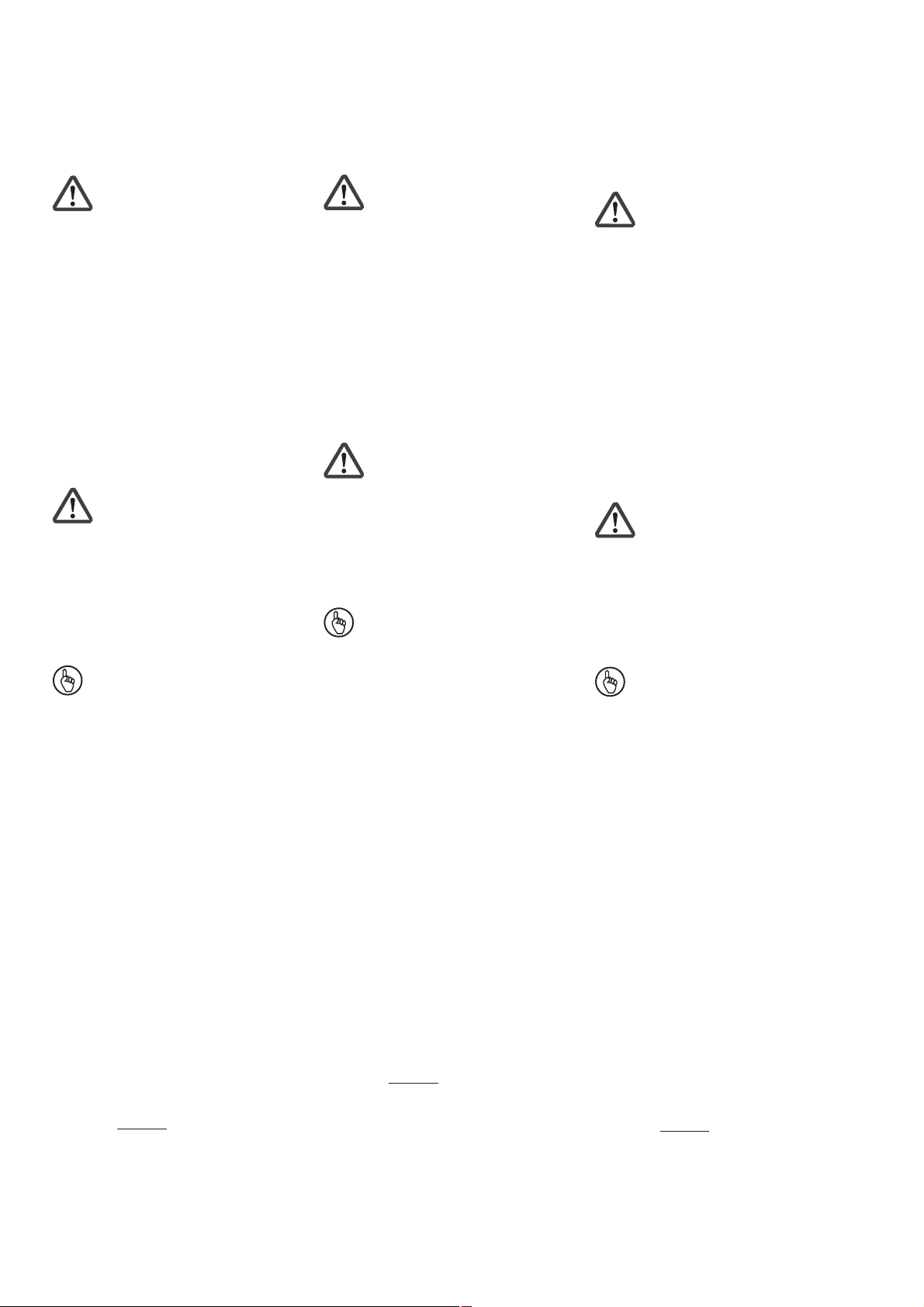
D
Anschlussbeispiel:
UND-Verknüpfung von Unit 1 und
Unit 2 und UNit 3, ODER-Verknüpfung von Unit 2 und Unit 3
L+
K2
K1
K3
K4
S1
GB
Connection example:
AND link Unit 1 and Unit 2 and Unit
3, OR link Unit 2 and Unit 3
F
Exemple de raccordement :
Liaison ET de l’unité 1 et unité 2 et
unité 3, liaison OU de l’unité 2 et
unité 3
S1
S2
K6
K5
K8
K7
S2
S1
K9
K10
A1
S11
S34Y4
S12Y6S13
A1
Unit 1 Unit 2 Unit 3
PNOZ e1p
A2
14
K2
K1
L-
K3
K4
S22
S21
Y32S12
Y524
K5
PNOZ e2.1p
A2
14
K6
K7
Steckbare Klemmen abziehen
Schraubendreher in Gehäuseaussparung
hinter der Klemme ansetzen und Klemme
heraushebeln.
Klemmen nicht an den Kabeln abziehen!
K8
S11
S36
S21
Y7
S23S22
Y32S35
Y524
S12Y6S13
A1
PNOZ e2.1p
A2
14
K10
K9
S11
S36
S21
Y7
S23S22
Y32S35
Y524
Remove plug-in terminals
Insert screwdriver into the cut-out of the
housing behind the terminal and lever the
terminal.
Do not remove the terminals by pulling the
cables!
S36
24
Unit 1
Unit 2
Unit 3
S35
14
&
Unit 3
24
>1
Démonter les borniers
débrochables
Placer un tournevis derrière les bornes et
sortir le bornier.
Ne pas retirer les borniers en tirant sur les
câbles !
Abziehen der Klemmen am Beispiel einer
Schraubklemme
How to remove the terminals using a screw
terminal as an example
- 8 -
Démontage d’un bornier à vis
Page 9

Technische Daten
Technical Details
Caractéristiques techniques
Elektrische Daten
Versorgungsspannung U
Spannungstoleranz U
Leistungsaufnahme bei U
ohne Last
Restwelligkeit U
B
B
B
B
Ausgänge, Halbleiter:
Sicherheitsausgänge (S)
Hilfsausgang (S)
Schaltvermögen
2 Ausgänge belastet
1 Ausgang belastet
Gesamtleistung, ext. Last,
Halbleiter
Spannung und Strom an
Eingangskreis, Rückführkreis
Hilfsausgang, Taktausgänge
UND/ODER-Eingänge
Anforderungsstufe
Konventioneller thermischer Strom
Geräteabsicherung
Max. Gesamtleitungswiderstand
R
(Eingangs- und Rück-
lmax
führkreis)
Sicherheitstechnische Kenndaten
PL nach EN ISO 13849-1
Kaskadiereingang
HL-Ausgang
Kategorie nach EN 954-1
Kaskadiereingang
HL-Ausgang
SIL CL nach EN IEC 62061
Kaskadiereingang
HL-Ausgang
PFH nach EN IEC 62061
Kaskadiereingang
HL-Ausgang
SIL nach IEC 61511
Kaskadiereingang
HL-Ausgang
PFD nach IEC 61511
Kaskadiereingang
HL-Ausgang
tM in Jahren
Zeiten
Überbrückung bei
Spannungseinbrüchen
Einschaltverzögerung
Ansprechzeit (Rückfallverzögerung)
Gleichzeitigkeit Eingangskreise
Einschaltverzögerung (bei erstem
Start nach Anlegen von UB)
Einschaltverzögerung an S35/S36
Ausschaltverzögerung an S35/S36
Max. Zeit der
Rückführkreisüberwachung
Electrical data
Supply voltage U
Voltage tolerance U
Power consumption at U
without load
Residual ripple U
B
B
B
B
Outputs, semiconductor:
Safety outputs (N/O)
Auxiliary output (N/O)
Switching capability
2 outputs under load
1 output under load
total power, ext. load,
semicondustor outputs
Voltage and current at
input circuit, feedback loop
Auxiliary output, test pulse outputs
AND/OR inputs
Requirement level
Conventional thermal current
Unit fuse protection
Max. overall cable resistance
R
(input circuit and feedback
lmax
loop)
Safety-related characteristic
data
PL in accordance with
EN ISO 13849-1
Cascading input
SC output
Category in accordance with
EN 954-1
Cascading input
SC output
SIL CL in accordance with
EN IEC 62061
Cascading input
SC output
PFH in accordance with
EN IEC 62061
Cascading input
SC output
SIL in accordance with IEC 61511
Cascading input
SC output
PFD in accordance with IEC 61511
Cascading input
SC output
tM in years
Times
Max. supply interruption
before de-energisation
Delay on energisation
Response time (Delay on de-
energisation)
Simultaneity of input circuits
Switch-on delay (at the first
reset after applying UB)
Switch-on delay at S35/S36
Switch-off delay at S35/S36
Max. time of feedback loop
monitoring
Données électriques
Tension d’alimentation U
B
Plage de la tension d’alimentation U
Consommation pour U
sans charge
Ondulation résiduelle U
B
B
Sorties statiques:
Sorties de sécurité (S)
Sortie d’information (S)
Caractéristiques de commutation
2 sorties chargées
1 sortie chargée
Puissance total, charge ext.,
sorties statiques
Tension et courant
Circuit d’entrée, boucle de retour
Sortie d’information, sorties
impulsionnelles
Entrées ET/OU
Niveau de sécurité
Courant thermique conventionnel
Protection du relais
Résistance de câblage totale max
R
(circuit d’entrée et boucle de
lmx
retour)
Caractéristiques techniques de
sécurité
PL selon EN ISO 13849-1
Entrée en cascade
Sortie HL
Catégorie selon EN 954-1
Entrée en cascade
Sortie HL
SIL CL selon EN IEC 62061
Entrée en cascade
Sortie HL
PFH selon EN IEC 62061
Entrée en cascade
Sortie HL
SIL selon IEC 61511
Entrée en cascade
Sortie HL
PFD selon IEC 61511
Entrée en cascade
Sortie HL
tM en années
Temps
Tenue aux
micro-coupures
Temps de montée
Temps de réaction (temporisation à
la retombée)
Synchronisme du circuit d’entrée
Temporisation d'enclenchement (au
premier démarrage après application
de UB)
Temporisation d’enclenchement sur
S35/S36
Temporisation de déclenchement sur
S35/S36
Temps max. de la surveillance de
la boucle de retour
24 V DC
80...125%
B
2 W
DC: 20%
2
1
UB ≤ 26,5 V: 2,0 A/50 W
UB > 26,5 V: 1,5 A/45 W
UB ≤ 26,5 V: 2,7 A/70 W
UB > 26,5 V: 2,2 A/65 W
130 W
24 V DC/5 mA
24 V DC/0,5 A
24 V DC/5 mA
EN 574, III C
4 A
max. 10 A flink/quick/rapide
oder/or/ou
max. 6 A träge/slow acting/
normal
2 kOhm
PL e (Cat. 4)
PL e (Cat. 4)
Cat. 4
Cat. 4
SIL CL 3
SIL CL 3
2,86E-10
3,44E-09
SIL 3
SIL 3
1,48E-05
4,53E-05
20
max. 20 ms
max. 180 ms, typ. 100 ms
40 ms
0,5 s -10%
3 s
max. 200 ms, typ. 120 ms
40 ms
150 ms
- 9 -
Page 10

Umweltdaten
EMV
Schwingungen nach
Frequenz
Amplitude
Klimabeanspruchung
Luft- und Kriechstrecken nach
EN 60947-1
Verschmutzungsgrad
Überspannungskategorie
Bemessungsisolationsspannung
Bemessungsstoßspannungsfestigkeit
Umgebungstemperatur
Lagertemperatur
Schutzart
Einbauraum (z. B. Schaltschrank)
Gehäuse
Klemmenbereich
Mechanische Daten
Querschnitt des Außenleiters
(Schraubklemmen)
1 Leiter
flexibel
2 Leiter gleichen Querschnitts
flexibel mit Aderendhülse ohne
Kunststoffhülse
flexibel ohne Aderendhülse oder
mit TWIN-Aderendhülse
Querschnitt des Außenleiters
(Federkraftklemmen)
flexibel ohne Aderendhülse
Gehäuse mit Federkraftklemmen
Abisolierlänge
Klemmstellen pro Anschluss
Anzugsdrehmoment für
Schraubklemmen
Gehäusematerial
Front
Gehäuse
Abmessungen (Schraubklemmen)
H x B x T
Abmessungen (Federkraftklemmen)
H x B x T
Gewicht
Environmental data
EMC
Vibration to
Frequency
Amplitude
Climatic suitability
Airgap Creepage in accordance with
EN 60947-1
Pollution degree
Overvoltage category
Rated insulation voltage
Rated impulse withstand voltage
Ambient temperature
Storage temperature
Protection type
Mounting (e.g. control cabinet)
Housing
Terminals
Mechanical data
Cable cross section (screw
terminals)
1 core
flexible
2 core, same cross section
flexible with crimp connectors,
without insulating sleeve
flexible without crimp connectors or
with TWIN crimp connectors
Cable cross section (spring-loaded
terminals)
flexible without crimp connectors
Housing with spring-loaded terminals
Stripping length
Terminal blocks per connection
Torque setting for screw terminals
Housing material
front panel
housing
Dimensions (screw terminals)
H x W x D
Dimensions (spring-loaded terminals)
H x W x D
Weight
Environnement
CEM
Vibrations selon
Fréquence
Amplitude
Sollicitations climatiques
Cheminement et claquage selon
EN 60947-1
Niveau d'encrassement
Catégorie de surtensions
Tension assignée d'isolement
Tension assignée de tenue aux chocs
Température d’utilisation
Température de stockage
Indice de protection
Lieu d'implantation (par
ex. armoire)
Boîtier
Borniers
Données mécaniques
Capacité de raccordement (borniers
à vis)
1 conducteur
souple
2 câbles de même diamètre
souple avec embout sans
chapeau plastique
souple sans embout ou avec
embout TWIN
Capacité de raccordement (borniers
à ressort)
souple sans embout
Boîtier avec borniers à ressort
Longueur de dénudage
bornes par raccordement
Couple de serrage (borniers à vis)
Matériau du boîtier
face avant
boîtier
Dimensions (borniers à vis)
H x L x P
Dimensions (borniers à ressort)
H x L x P
Poids
EN 60947-5-1, EN 61000-62, EN 61000-6-4
EN 60068-2-6
10 ... 55 Hz
0,35 mm
EN 60068-2-78
2
III
60 V
0,8 kV
-10 ... + 55 °C
-25 ... + 70 °C
IP54
IP40
IP20
0,25 ... 2,5 mm2/24-12 AWG
0,25 ... 1 mm2/24-16 AWG
0,20 ... 1,5 mm2/
0,20 ... 1,5 mm2/24-16 AWG
8 mm
2
0,5 Nm
ABS UL 94 V0
PPO UL 94 V0
94 x 22,5 x 121 mm
101 x 22,5 x 121 mm
135 g
24-16 AWG
Es gelten die 2008-08 aktuellen Ausgaben
der Normen.
The version of the standards current at
2008-08 apply.
Se référer à la version des normes en
vigeur au 2008-08.
- 10 -
Page 11

4GB Dimensions in mm (") 4F Dimensions en mm (")4D Abmessungen in mm (")
Gehäuse mit steckbaren Schraubklemmen/
Housing with plug-in screw terminals/
Boîtier avec borniers débrochables à vis
121 (4.76")
75 (2.95")
87 (3.42")
94 (3.70")
22,5
(0.88")
Gehäuse mit steckbaren Federkraftklemmen/
Housing with plug-in spring-loaded terminals/
Boîtier avec borniers débrochables à ressort
121 (4.76")
75 (2.95")
87 (3.42")
101 (3.98")
4E Asignación de conexiones 4I Schema delle connessioni 4NL Klembezetting
22,5
(0.88")
EG-Konformitätserklärung:
Diese(s) Produkt(e) erfüllen die Anforderungen der Richtlinie 2006/42/EG über
Maschinen des europäischen Parlaments
und des Rates.
Die vollständige EG-Konformitätserklärung
finden Sie im Internet unter www.pilz.com
Bevollmächtigter: Norbert Fröhlich,
Pilz GmbH & Co. KG, Felix-Wankel-Str. 2,
73760 Ostfildern, Deutschland
1
2
3
EC Declaration of Conformity:
This (these) product(s) comply with the
requirements of Directive 2006/42/EC of the
European Parliament and of the Council on
machinery.
The complete EC Declaration of Conformity
is available on the Internet at www.pilz.com
Authorised representative: Norbert Fröhlich,
Pilz GmbH & Co. KG, Felix-Wankel-Str. 2,
73760 Ostfildern, Germany
Déclaration de conformité CE :
Ce(s) produit(s) satisfait (satisfont) aux
exigences de la directive 2006/42/CE
relative aux machines du Parlement
Européen et du Conseil.
Vous trouverez la déclaration de conformité
CE complète sur notre site internet
www.pilz.com
Représentant : Norbert Fröhlich,
Pilz GmbH & Co. KG, Felix-Wankel-Str. 2,
73760 Ostfildern, Allemagne
- 11 -
Page 12

Notizen
Notes
Notes
Technischer Support
+49 711 3409-444 +49 711 3409-444
...
In vielen Ländern sind wir durch
unsere Tochtergesellschaften und
Handelspartner vertreten.
Nähere Informationen entnehmen
Sie bitte unserer Homepage oder
nehmen Sie Kontakt mit unserem
Stammhaus auf.
Technical support
... ...
In many countries we are
represented by our subsidiaries
and sales partners.
Please refer to our Homepage
for further details or contact our
headquarters.
Assistance technique
+49 711 3409-444
Nos filiales et partenaires
commerciaux nous représentent
dans plusieurs pays.
Pour plus de renseignements,
consultez notre site internet ou
contactez notre maison mère.
- 12 -
www
www.pilz.com
Pilz GmbH & Co. KG
Felix-Wankel-Straße 2
73760 Ostfildern, Germany
Telephone: +49 711 3409-0
Telefax: +49 711 3409-133
E-Mail: pilz.gmbh@pilz.de
Originalbetriebsanleitung/Original instructions/Notice originale
21386-3FR-04, 2010-05 Printed in Germany
 Loading...