

Page 1

21238-3FR-04
PNOZ e1.1p
4
D Betriebsanleitung
4
GB Operating instructions
4
F Manuel d'utilisation
Sicherheitsschaltgerät PNOZ e1.1p
Das Sicherheitsschaltgerät PNOZ e1.1p
dient dem sicherheitsgerichteten Unterbrechen eines Sicherheitsstromkreises. Das
Gerät erfüllt Forderungen der EN 954-1 oder
EN ISO 13849-1 bis Kategorie 4.
Das Gerät ist bestimmt für den Einsatz in:
• Not-Halt-Einrichtungen
• Sicherheitsstromkreisen nach VDE 0113-1
und EN 60204-1 (z. B. bei beweglichen
Verdeckungen)
Wichtige Daten für Projektierung und
Anwendung finden Sie auch im technischen
Katalog PNOZelog.
Zu Ihrer Sicherheit
Das Sicherheitsschaltgerät PNOZ e1.1p
erfüllt alle notwendigen Bedingungen für
einen sicheren Betrieb.
Beachten Sie jedoch nachfolgend aufgeführte Sicherheitsbestimmungen:
• Installieren und nehmen Sie das Gerät nur
dann in Betrieb, wenn Sie diese Betriebsanleitung gelesen und verstanden haben
und Sie mit den geltenden Vorschriften
über Arbeitssicherheit und Unfallverhütung
vertraut sind.
• Verwenden Sie das Gerät nur gemäß
seiner Bestimmung. Beachten Sie dazu
auch die Werte im Abschnitt “Technische
Daten”.
• Halten Sie beim Transport, bei der
Lagerung und im Betrieb die Bedingungen
ein, wie sie unter "Technische Daten"
angegeben sind.
• Öffnen Sie nicht das Gehäuse und
nehmen Sie auch keine eigenmächtigen
Umbauten vor.
• Schalten Sie bei Wartungsarbeiten (z. B.
beim Austausch von Schützen) unbedingt
die Versorgungsspannung ab oder öffnen
Sie den Eingangskreis (z. B. Not-HaltTaster betätigen), sonst kann das Gerät
bei Verdrahtungsfehlern unerwartet
einschalten.
Beachten Sie unbedingt die Warnhinweise in
den anderen Abschnitten dieser Anleitung.
Diese Hinweise sind optisch durch Symbole
hervorgehoben.
Wichtig: Beachten Sie die Sicherheitsbestimmungen, sonst erlischt
jegliche Gewährleistung.
Safety Relay PNOZ e1.1p
The safety relay PNOZ e1.1p is used for the
safety-related interruption of a safety circuit.
The unit meets requirements of EN 954-1 or
EN ISO 13849-1 up to category 4.
The unit is intended for use in:
• Emergency stop circuits
• Safety circuits to VDE 0113-1 and
EN 60204-1 (e.g. with moveable guards)
Important data for project planning and
application can also be found in the
PNOZelog technical catalogue.
For your safety
The safety relay PNOZ e1.1p meets all the
necessary conditions for safe operation.
However, please note the following safety
regulations:
• Only install and commission the unit if you
have read and understood these
instructions and are familiar with both
these instructions and the current
regulations for health and safety at work
and accident prevention.
• Only use the unit in accordance with its
intended purpose. Please also take note of
the values in the “Technical details”
section.
• Transport, storage and operating
conditions should all conform to the
standards as stated under “Technical
details”.
• Do not open the housing or undertake any
unauthorised modifications.
• Please make sure you shut down the
supply voltage, or open the input circuit
(e.g. operate the E-STOP button) when
performing maintenance work (e.g. when
replacing contactors). In case of a wiring
error, the device might switch on
unexpectedly.
You must take note of the warnings given in
other sections of these operating instructions.
These are highlighted visually through the
use of symbols.
Notice: Failure to keep to these safety
regulations will render all warranty
invalid.
Bloc logique de sécurité PNOZ e1.1p
Le bloc logique de sécurité PNOZ e1.1p
assure de façon sûre l'ouverture d'un circuit
de sécurité. L’appareil satisfait aux exigences
de l’EN 954-1, EN ISO 13849-1 jusqu’en
catégorie 4.
L'appareil est spécialement conçu pour :
• les circuits d'arrêt d'urgence
• les circuits de sécurité selon VDE 0113-1
et EN 60204-1 (par ex., protecteurs
mobiles)
Vous trouverez également des données
importantes pour la configuration projet et
l’utilisation dans le Catalogue technique
PNOZelog.
Pour votre sécurité
Le bloc logique de sécurité PNOZ e1.1p
satisfait à toutes les conditions nécessaires
pour un fonctionnement sécuritaire.
Toutefois, vous êtes tenu de respecter les
prescriptions de sécurité suivantes :
• Vous n’installerez l’appareil et ne le
mettrez en service qu’après avoir lu et
compris le présent manuel d’utilisation et
que si vous êtes familier avec les prescriptions en vigueur sur la sécurité du travail et
la prévention d’accidents.
• N'utilisez l'appareil que conformément à sa
définiton. A ce sujet, respectez les valeurs
indiquées dans les "Caractéristiques
techniques".
• Pour le transport, le stockage et
l'utilisation, respectez les exigences des
normes specifiées (voir „Caractéristiques
techniques“).
• N’ouvrez pas le boîtier et n'effectuez pas
de modifications non autorisées.
• En cas de travaux de maintenance (par
ex. remplacement des contacteurs) coupez
impérativement la tension d’alimentation ou
ouvrez le circuit d’entrée (action sur le BP
d’arrêt d’urgence), sinon un réarmement
inopiné du relais est possible en cas
d’erreur de câblage.
Respectez impérativement les avertissements
dans les autres paragraphes du présent
manuel d’utilisation. Ces avertissements sont
signalés par des symboles visuels.
Important : Respectez les consignes
de sécurité, sinon la garantie devient
caduque.
- 1 -
Page 2

Gerätebeschreibung
Sicherheitseigenschaften
Das Sicherheitsschaltgerät erfüllt folgende
Sicherheitsanforderungen:
• Die Schaltung ist redundant mit Selbstüberwachung aufgebaut.
• Die Sicherheitseinrichtung bleibt auch bei
Ausfall eines Bauteils wirksam.
• Die Sicherheitsausgänge werden durch
einen Abschalttest periodisch geprüft.
• Das Gerät besitzt eine elektronische
Sicherung.
Gerätemerkmale
• Ausgänge in Halbleitertechnik:
2 Sicherheitsausgänge, 1 Hilfsausgang
und 2 Taktausgänge
• Anschlussmöglichkeit für Not-Halt-Taster,
Schutztürgrenztaster, Starttaster, Schaltmatten und Schaltleisten der Fa. Haake,
Auswertegeräte von Näherungsschaltern
• zur Verarbeitung von Signalen aus
Ausgangsschalteinrichtungen von
Schaltmatten oder aus Ausgangsschaltelementen von Lichtschranken
• Hilfsausgang umschaltbar als Diagnoseausgang
• UND- und ODER-Eingang zur logischen
Verknüpfung mehrerer Geräte
• Querschlussüberwachung durch Taktausgänge
• Statusanzeige
• Rückführkreis zur Überwachung externer
Schütze
Description
Safety features
The safety relay fulfils the following safety
requirements:
• The circuit is redundant with built-in selfmonitoring.
• The safety function remains effective in the
case of a component failure.
• The safety outputs are tested periodically
using a disconnection test.
• The unit has an electronic fuse.
Unit features
• Outputs use semiconductor technology:
2 safety outputs, 1 auxiliary output and
2 test pulse outputs
• Connection for E-STOP button, safety gate
limit switch, reset button, safety mats and
connecting blocks made by Haake,
evaluation devices for proximity switches
• Processes signals from output switching
elements on safety mats or light barriers
• Auxiliary output can be used as a
diagnostic output
• AND/OR input for logic links between
several units
• Test pulse outputs monitor shorts across
the input contacts
• Status display
• Feedback loop for monitoring external
contactors
Description de l’appareil
Propriétés de sécurité
Le bloc logique de sécurité satisfait aux
exigences de sécurité suivantes :
• Conception redondante avec autosurveillance.
• Fonction de sécurité garantie même en
cas de défaillance d'un composant interne
• Les sortie de sécurité sont testées
périodiquement à l'aide d'un test de
coupure.
• L'appareil est équipé d'un fusible
électronique.
Caractéristiques de l’appareil
• Sorties statiques :
2 sorties de sécurité, 1 sortie d'information
et 2 sorties impulsionnelles
• Possibilités de raccordement de boutons
d'arrêt d'urgence, d'interrupteurs de
position, de poussoir de validation, de
tapis et bords sensibles de la Sté Haake,
d' unités de contrôle de détecteurs inductifs
• Traitement des signaux de sortie d'unités
de contrôle de tapis sensibles et de
barrières lumineuses
• Temporisation à la retombée réglable
• Sortie d'information commutable en sortie
de diagnostic
• Entrées ET et OU pour le couplage
logique de plusieurs appareils
• Surveillance des courts-circuits par sorties
impulsionnelles
• Affichage de l’état
• Boucle de retour pour le contrôle des
contacteurs externes
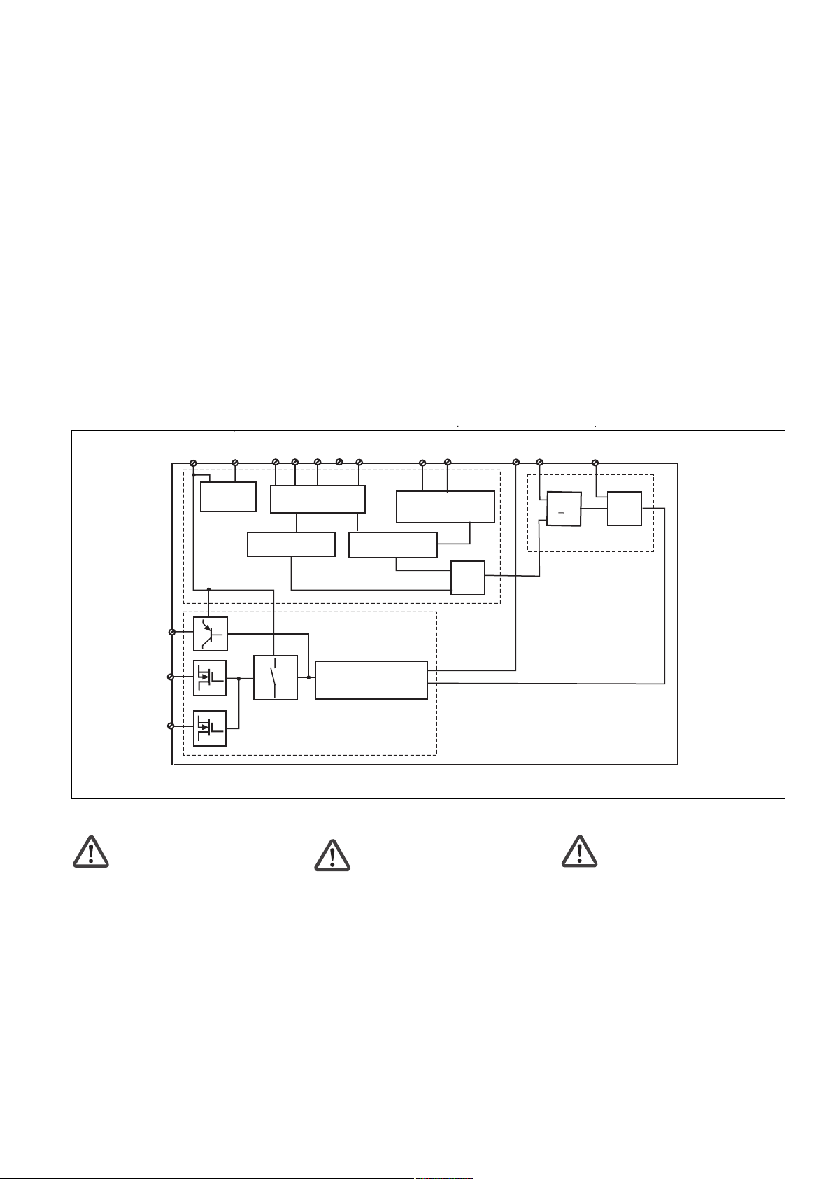
Funktionsbeschreibung
Arbeitsweise
Zwei Mikro-Controller werten die Eingangskreise aus und schalten abhängig davon die
Ausgänge. Die Mikro-Controller überwachen
sich gegenseitig.
Zustand der Ausgänge
• Eingangskreis geschlossen (z. B. Not-HaltTaster nicht betätigt).
Die Sicherheitsausgänge 14 und 24 und
der Hilfsausgang Y32 leiten.
• Eingangskreis wird geöffnet (z. B. NotHalt-Taster betätigt).
Die Sicherheitsausgänge 14 und 24 und
der Hilfsausgang Y32 sind gesperrt.
Funktionen
• Wenn an den Eingang Y5 für mindestens
250 ms ein High-Signal (+24 V DC) gelegt
wird, wechselt der Ausgang Y32 in die
Diagnosefunktion. Die Ansteuerung
erfolgt über einen Treiber, der als Zubehör
zur Verfügung steht oder selbst erstellt
werden kann. Ist der Eingang Y5 offen
oder Low, funktioniert Y32 wie ein
Hilfsausgang.
• Zur logischen Verknüpfung mehrerer
Geräte besitzt das PNOZ e1.1p einen
UND- und einen ODER-Eingang. Die
Eingänge weisen Schaltverzögerungen
auf, die sich im Falle einer UND-Verknüpfung addieren.
Betriebsarten
• Einkanaliger Betrieb: Eingangsbe-
schaltung nach EN 60204, keine Redundanz im Eingangskreis; Erdschlüsse im
Tasterkreis werden erkannt.
• Zweikanaliger Betrieb: Redundanter
Eingangskreis; Erdschlüsse im Tasterkreis
werden erkannt, mit oder ohne Querschlusserkennung zwischen den Tasterkontakten.
Function
Operation
Two microcontrollers evaluate the input
circuits and switch the outputs accordingly.
The microcontrollers monitor each other.
Output status
• Input circuit closed (e.g. E-STOP button is
not operated)
Safety outputs 14 and 24 and auxiliary
output Y32 are energised.
• Input circuit is open (e.g. E-STOP button is
operated).
Safety outputs 14 and 24 and auxiliary
output Y32 are de-energised.
Functions
• If there is a high signal (+24 VDC) at input
Y5 for at least 250 ms, output Y32
switches to diagnostic mode. It is
controlled via a driver that is available as
an accessory or that you can create
yourself. If input Y5 is open or low, Y32 will
operate as an auxiliary output.
• For logic links between several units, the
PNOZ e1.1p has one AND and one OR
input. The inputs have a time delay,
which is added in the case of an AND
connection.
Operating modes
• Single-channel operation: input wiring to
EN 60204, no redundancy in the input
circuit; earth faults in the pushbutton circuit
are detected.
• Dual-channel operation: redundant input
circuit; earth faults in the pushbutton circuit
are detected, with or without detection of
shorts between the pushbutton contacts.
• Automatic reset: unit becomes active as
soon as the input circuit is closed.
Descriptif du fonctionnement
Fonctionnement
Deux micro-processeurs analysent les
circuits d'entrée et pilotent en conséquence
les sorties. Les micro-processseurs se
contrôlent mutuellement.
Etat des sorties
• Circuit d’entrée fermé (par exemple le
poussoir d’AU n’a pas été activé)
Mise sous tension des sorties de sécurité
14 et 24 et de la sortie d'information Y32.
• Circuit d’entrée ouvert (par exemple le
poussoir d’AU a été activé).
Blocage des sorties de sécurité 14 et 24 et
de la sortie d'information Y32.
Fonctions
• Si un signal Haut (+24 V CC) est appliqué
sur l’entrée Y5 pendant au moins 250 ms,
la sortie Y32 commute en sortie
diagnostic. Son exploitation est réalisée
via un protocole disponible en tant
qu'accessoire ou développé par
l'utilisateur. Si l’entrée Y5 est ouverte ou
Bas, Y32 fonctionne comme une sortie
d'information.
• Pour le couplage logique de plusieurs
appareils, le PNOZ e1.1p possède une
entrée ET et une entrée OU. Les entrées
ont une temporisation de couplage qui est
cumulative dans le cas d’une liaison ET.
Modes de fonctionnement
• Commande par 1 canal : Câblage des
entrées selon EN 60204, pas de
redondance sur le circuit d’entrée ; la mise
à la terre du circuit d’entrée est détectée.
• Commande par 2 canaux : Circuit
d’entrée redondant ; la mise à la terre du
circuit d’entrée est détectée, avec ou sans
détection des court-circuits entre les
contacts de l'élément de commande.
- 2 -
Page 3
• Automatischer Start: Gerät ist aktiv,
sobald der Eingangskreis geschlossen ist.
• Überwachter Start: Gerät ist erst aktiv,
wenn der Starttaster betätigt und wieder
losgelassen wurde. Dadurch ist eine
automatische Aktivierung und Überbrückung des Starttasters ausgeschlossen.
• Querschlusserkennung wird durch
Taktung der Eingangskreise ermöglicht.
Diese Betriebsart wird beim Start automatisch erkannt.
• Anlauftest verhindert einen automati-
schen Wiederanlauf nach Spannungsausfall und -wiederkehr. Das Gerät prüft,
ob nach Anlegen der Versorgungsspannung geschlossene Schutztüren geöffnet
und wieder geschlossen werden.
• Kontaktvervielfachung und -verstärkung
durch Anschluss eines Kontaktblockes
(z. B. PZE X4.1P) oder von externen
Schützen.
U
A1
B
A2
S12
• Monitored reset: unit is active when the
reset button is pressed and then released.
This prevents an automatic reset and
linking of the reset button.
• Shorts between contacts can be
detected by pulsing the input circuits. This
operating mode is detected automatically
on start-up.
• Start-up test prevents an automatic
restart when power is restored following a
voltage loss. The unit checks whether
closed safety gates are opened and closed
again when operating voltage is applied.
• The number of safety contacts can be
increased by connecting a contact block
(e.g. PZE X4.1P) or external contactors.
S34
S22
Y4
Y5
S21
S11
Y6
• Réarmement automatique : L’appareil
est actif dès que le circuit d’entrée est
fermé.
• Réarmement auto-contrôlé : L’appareil
n’est activé qu’après avoir appuyé sur le
poussoir de réarmement et après avoir
relâché le bouton. De ce fait un réarmement automatique ou un pontage du
poussoir de réarmement est impossible.
• La détection des court-circuits est rendue
possible par test impulsionnel des circuits
d’entrée. Ce mode de fonctionnement est
identifié automatiquement lors du
réarmement.
• Le test des conditions initiales prévient
le redémarrage automatique après
coupure/rétablissement de la tension
d'alimentation. L’appareil vérifie si les
protecteurs mobiles qui étaient fermées
après application de la tension
d’alimentation ont été ouverts puis
refermés.
• Augmentation du nombre de contacts
ou de leur pouvoir de coupure par le
raccordement d’un bloc de contacts
d'extension (par exemple PZE X4.1P) ou
de contacteurs externes.
S35
S36
Netzteil/
Power unit/
Alimentation
µController 1
Y32
14
24
Innenschaltbild
Sicherheitsschaltgerät montieren
Achtung! Durch elektrostatische
Entladung können Bauteile des
Sicherheitssystems beschädigt
werden. Sorgen Sie für Entladung,
bevor Sie das Sicherheitssystem
berühren, z. B. durch Berühren einer
geerdeten, leitfähigen Fläche oder
durch Tragen eines geerdeten
Armbands.
• Montieren Sie das Sicherheitsschaltgerät
in einen Schaltschrank mit einer Schutzart
von mindestens IP54.
• Befestigen Sie das Gerät mit Hilfe des
Rastelements auf der Rückseite auf einer
Normschiene.
• Sichern Sie das Gerät auf einer senkrechten Tragschiene (35 mm) durch ein
Halteelement (z. B. Endhalter oder
Endwinkel)
Eingangsschaltung/
Input circuit/
Circuit d'entrée
Rückführkreis/
Feedback control loop/
Boucle de retour
Taktausgänge/
test pulse outputs/
Sorties impulsionnelles
µController 2
Internal wiring diagram
Installing the relay
Caution! Electrostatic discharge can
damage components on the safety
system. Ensure against discharge
before touching the safety system,
e.g. by touching an earthed,
conductive surface or by wearing an
earthed armband.
• Install the safety relay in a control cabinet
with a minimum protection type of IP54.
• Use the notch on the rear of the unit to
attach it to a DIN-rail.
• Attach the unit securely to a vertical DIN
rail (35 mm) using a fixture such as a
retaining bracket or end angle.
>1
&
&
Schéma interne
Installer le bloc logique de sécurité
Attention ! Une décharge électro-
statique peut endommager les
éléments du système de sécurité.
Veillez à vous décharger avant de
toucher le système de sécurité, par
ex. en touchant une surface
conductrice mise à la terre ou en
portant un bracelet de mise à la
terre.
• Installez le bloc logique de sécurité dans
une armoire d’indice de protection au
moins IP54.
• Montez l'appareil sur un rail DIN à l'aide du
système de fixation situé au dos du relais.
• Fixer l’appareil sur un rail DIN vertical (35
mm) avec un élément de maintien comme
par ex. un support ou une équerre
terminale.
- 3 -
Page 4
Achtung!
UND-/ODER- Verknüpfung:
• Montieren Sie alle über die UND-/
ODER- Eingänge verknüpften
Geräte im gleichen Schaltschrank
oder
• Stellen Sie sicher, dass Fehler
über die Verbindung der Geräte
ausgeschlossen werden z. B.
durch geschützte Verlegung der
Verbindungsleitung.
Caution!
AND-/OR connection:
• Install all the devices that are
linked via the AND/OR inputs in
the same control cabinet
or
• make sure that faults that occur
from the connection of the devices
can be excluded, e.g. by secure
laying of connection cables.
Attention!
Liaison ET/OU :
• Montez l'ensemble des appareils
reliés via les entrées ET/OU dans
la même armoire électrique
ou
• assurez-vous que la connexion
des appareils n'entraîne pas
d'erreurs, en protégeant, par
exemple, les câbles de
raccordement entre les appareils.
Sicherheitsschaltgerät in Betrieb
nehmen
Inbetriebnahme vorbereiten
Beachten Sie bei der Vorbereitung der
Inbetriebnahme:
• Das Gerät und die Eingangskreise müssen
immer aus einem Netzteil versorgt werden.
• Verwenden Sie Leitungsmaterial aus
Kupferdraht mit einer Temperaturbeständigkeit von 60/75°C.
• Berechnung der max. Leitungslänge I
am Eingangs-, Start und Rückführkreis:
R
lmax
=
Rl / km
= max. Gesamtleitungs-
lmax
widerstand (s. technische Daten)
R
I
max
Rl /km = Leitungswiderstand/km
• Ausgang 14, 24: bei Leerlauf eine
Kapazität bis max. 2 nF ansteuerbar
• Setzen Sie die Sicherheitsausgänge 14
und 24 für sichere Anwendungen ein.
Die Sicherheitsausgänge dürfen nicht mit
SPS-Eingängen verbunden werden.
Um die Ausschaltimpulse an den
Halbleiterausgängen 14 und 24 zu
unterdrücken, setzen Sie die Reihenklemme mit Filter Bestellnummer 774195
oder 774196 ein.
• Der Ausgang Y32 dient ausschließlich als
Hilfsausgang z. B. für die Kommunikation
mit einer SPS oder einer Anzeige.
• Verwenden Sie Freilaufdioden, wenn Sie
mit den Sicherheits-/Hilfsausgängen
Schütze oder Relais ansteuern.
• Sorgen Sie beim Anschluss von magnetisch wirkenden, auf Reedkontakten
basierenden Näherungsschaltern dafür,
dass der max. Einschaltspitzenstrom (am
Eingangskreis) den Näherungsschalter
nicht überlastet.
Betriebsbereitschaft herstellen
• Legen Sie die Versorgungspannung an:
Klemme A1(+) : + 24 V DC
Klemme A2(-) : 0 V
• Legen Sie die Betriebsart mit/ohne
Querschlusserkennung durch Verdrahten
des Eingangskreises fest.
max
Commissioning the safety relay
Preparing for commissioning:
Please note the following when preparing for
commissioning:
• Voltage for the unit and the input circuits
must always be provided from a single
power supply.
• Use copper wire that will withstand
temperatures of 60/75°C.
• Calculating the max. cable length I
the input circuit, reset circuit and feedback
loop:
R
lmax
=
Rl / km
= max. overall cable resistance (see
lmax
Technical details)
R
I
max
Rl /km = cable resistance/km
• Output 14, 24: when idling, a capacity of a
max. 2 nF can be controlled
• Safety outputs 14 and 24 should be used
for safe applications. The safety outputs
must not be connected to PLC inputs.
In order to suppress the pulses on switchoff on the semiconductor outputs 14 and
24, the terminal block with filter, order
number 774195 or 774196 should be
used.
• Output Y32 should be used exclusively as
an auxiliary output, e.g. for communication
with a PLC or display.
• Use flywheel diodes to drive contactors or
relays with the safety/auxiliary outputs.
• When connecting magnetically operated,
reed proximity switches, ensure that the
max. peak inrush current (on the input
circuit) does not overload the proximity
switch.
Preparing the unit for operation
• Connect the supply voltage.
Terminal A1(+) : +24 VDC
Terminal A2(-) : 0 V
• Establish the operating mode with/without
detection of shorts across input contacts
through the wiring of the input circuit.
max
at
Mettre en service le bloc logique
Préparer la mise en service :
Pour préparer la mise en service, respectez
les consignes suivantes :
• L’appareil et les circuits d’entrée doivent
toujours être reliés à la même source
d'alimentation.
• Utilisez des fils de câblage en cuivre
supportant des températures 60/75°C.
• Calcul de la longueur de conducteur I
sur le circuit d’entrée, le circuit de
réarmement et boucle de retour :
R
lmax
=
Rl / km
= Résistivité de câblage totale max.
lmax
(voir les caractéristiques techniques)
R
I
max
Rl /km = résistance du câble/km
• Sortie 14, 24 : en cas de coupure à vide,
capacité max. de 2 nF pilotable.
• Utilisez les sorties de sécurité 14 et 24
dans les circuits de sécurité. Les sorties de
sécurité ne doivent pas être raccordées à
des entrées d’API.
Pour supprimer l'impulsion de coupure aux
sorties statiques 14 et 24, utilisez les
bornes avec filtre, référence 774195 ou
774196.
• Utilisez la sortie Y32 exclusivement
comme sortie d'information pour la
communication par ex. avec un API ou un
afficheur.
• Utilisez des diodes de roue libre lorsque
vous commandez des contacteurs ou des
relais au moyen des sorties de sécurité/
d’information.
• Lors du raccordement de détecteurs de
proximité magnétiques, basés sur des
contacts Reed, veuillez vous assurer que
le courant de crête max. à la mise sous
tension (sur le circuit d'entrée) ne
surcharge pas les détecteurs de proximité.
Mettre en œuvre le système
• Appliquez la tension d’alimentation.
borne A1(+) : + 24 V CC
borne A2(-) : 0 V
• Choisissez le mode avec/sans détection
des court-circuits par câblage du circuit
d’entrée.
max
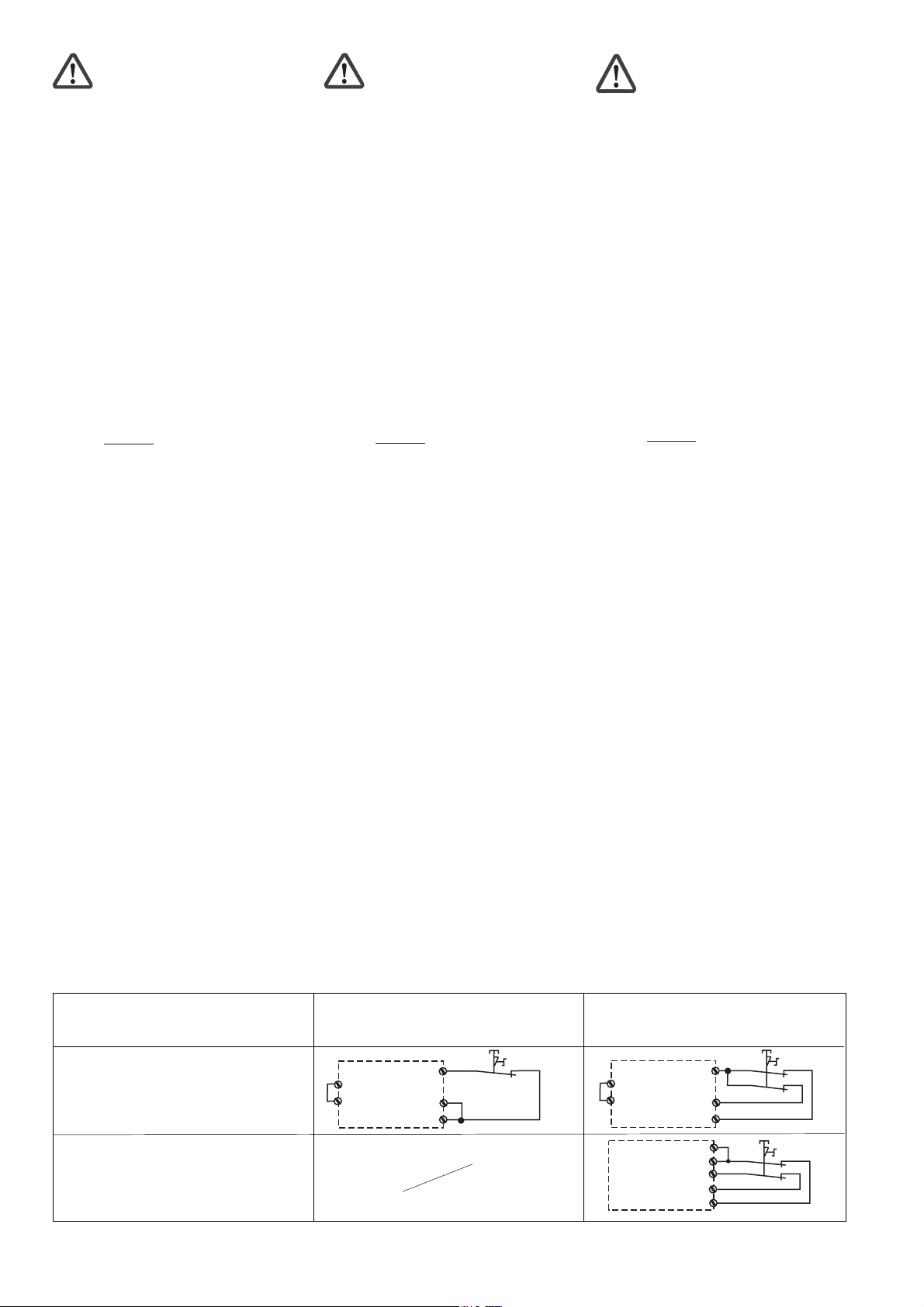
Eingangskreis
Input circuit
Circuit d’entrée
ohne Querschlusserkennung
without detection of shorts across contacts
sans détection des court-circuits
mit Querschlusserkennung
with detection of shorts across contacts
avec détection des court-circuits
➀ "Not-Halt" symbolisiert Öffnerkontakt
des Auslöseelements
Einkanalig
Single-channel
Commande par 1 canal
S1
Y4
S11
A1
S12
S22
➀ “E-STOP” symbolises N/C contact
on the trigger element
- 4 -
Zweikanalig
Dual-channel
Commande par 2 canaux
S1
S1
➀
➀
➀
S12
S22
Y4
S21
S11
S12
S22
A1
Y4
S11
➀ „Arrêt d’urgence“ symbolise le contact à
de l'élément de commande
Page 5

• Stellen Sie die Starteigenschaften durch
S34
S3
A1
Verdrahten des Startkreises ein.
• Set the reset features through the wiring of
the reset circuit.
• Déterminez le type de réarmement par
câblage du circuit de réarmement.
Eingangskreis
Input circuit
Circuit d’entrée
Not-Halt-Beschaltung
E-STOP circuit
Circuit d’arrêt d’urgence
Schutztür ohne Anlauftest
Safety gate without start-up test
Protecteur mobile sans test des conditions
initiales
Schutztür mit Anlauftest
Safety gate with start-up test
Protecteur mobile avec test des conditions
initiales
• Schließen Sie den Rückführkreis, indem
Sie Y6-A1 brücken oder die Kontakte
externer Schütze zwischen Y6 und A1
anschließen.
Achtung! Schließen Sie nicht die
Kontakte der externen Schütze in
Reihe zum Startkreis an.
Der Rückführkreis wird überwacht.
Spätestens 150 ms nach dem Ausschalten
des jeweiligen Ausgangs muss der
Rückführkreis wieder geschlossen sein.
Sicherheitsschaltgerät einzeln verwenden
Bitte beachten Sie:
Wenn Sie das PNOZ e1.1p allein verwenden, verdrahten Sie wie bei der ODERVerknüpfung (siehe "Sicherheitsschaltgeräte
verknüpfen").
Sicherheitsschaltgeräte verknüpfen
Beachten Sie beim Verknüpfen mehrerer
Geräte:
• Das Verknüpfen von PNOZ e1p ist erst ab
Version 3.0 zulässig.
• Sicherheitsausgänge, an denen Lasten
angeschlossen sind, dürfen zusätzlich mit
den Sicherheitseingängen von max. 4
PNOZelog-Geräten verbunden werden.
• Sie dürfen ausschließlich Sicherheitsausgänge von PNOZelog-Geräten von Pilz
UND/ODER-verknüpfen. Das Gerät mit der
niedrigsten Kategorie bestimmt die
Kategorie nach EN 954-1 der Gesamtschaltung.
• Alle verknüpften Geräte müssen an die
gleiche Versorgungsspannung angeschlossen werden.
UND-/ODER-Verknüpfung
Warnung! Das Ausgangssignal
eines PNOZelog-Geräts am ODEREingang überbrückt die Sicherheitsfunktion des Geräts. Die
Sicherheitsausgänge leiten dann
unabhängig vom Zustand der
Eingangskreise.
Automatischer Start
Automatic reset
Réarmement automatique
S11
S34
S21
S34
• Close the feedback loop by linking Y6-A1
or connecting the external contactors
between Y6 and A1.
Caution! Do not connect the
external contactors in series to the
reset circuit.
The feedback loop is monitored. The
feedback loop must be closed a maximum
of 150 ms after the respective output has
switched off.
Using the safety relay as a single unit
Please note:
If you are using the PNOZ e1.1p on its own,
make the OR connection (see "Linking the
units").
Linking the units
When linking several units, please note:
• The PNOZ e1p can only be linked from
version 3.0.
• Safety outputs which have loads
connected may also be linked to the safety
inputs of a max. of 4 PNOZelog units.
• Only safety outputs on Pilz PNOZelog
units may be AND/OR connected. The unit
with the lowest category determines the
category of the whole circuit in accordance
with EN 954-1.
• All linked units must be connected to the
same supply voltage.
AND/OR connection
Warning! The output signal from a
PNOZelog device at the OR input will
bridge the unit’s safety function. The
safety outputs will then energise,
irrespective of the status of the input
circuits.
Überwachter Start
Monitored reset
Réarmement auto-contrôlé
• Raccordez la boucle de retour en court-
circuitant Y6-A1 ou en raccordant les
contacts des contacteurs externes entre
Y6 et A1.
Attention ! Ne pas raccorder les
contacts des contacteurs externes
en série avec le circuit de
réarmement.
La boucle de retour est contrôlée. Au plus
tard 150 ms après le déclenchement de la
sortie correspondante, la bouche de retour
doit être refermée.
Utilisation séparée du bloc loquique de
sécurité
Veuillez noter s.v.p. :
Si vous souhaitez utiliser le PNOZ e1.1p
séparément, câblez-le comme le couplage
OU (voir "Coupler les blocs logiques de
sécurité").
Coupler les blocs logiques de sécurité
Veuillez noter les points suivants en cas de
couplage de plusieurs relais :
• Le couplage de PNOZ e1p n’est permis
qu’à partir de version 3.0.
• Les sorties utilisées pour piloter des
charges, peuvent être raccordées en plus
au max. à 4 entrées de sécurité de relais
de la gamme PNOZelog.
• Seules les sorties de sécurité des relais
PNOZelog peuvent être utilisées pour le
couplage ET/OU. Le relais de plus petite
catégorie détermine la catégorie de
l'ensemble du circuit.
• Tous les appareils raccordés entre eux
doivent être reliés à la même source
d'alimentation.
Couplage ET/OU
Attention ! Le signal de sortie d'un
appareil PNOZelog sur l’entrée OU
ponte la fonction de sécurité de
l’appareil. Les sorties de sécurité
sont alors sous tension,
indépendamment de l’état des
circuits d’entrée.
- 5 -
Page 6

Y4
S36
14/24
PNOZ e1.1p
Unit 1
AND
A1
Eingangskreis
Input circuit
Circuit d’entrée
ohne Querschlusserkennung
without detection of shorts across contacts
sans détection des court-circuits
UND und ODER
UND and OR
ET et OU
14/24
Unit 1
14/24
Unit 2
AND
OR
➀
Y4
A1
S36
S35
PNOZ e1.1p
UND
UND
ET
ODER
OR
OU
➀
14/24
Unit 1
OR
Y4
S11
S35
PNOZ e1.1p
mit Querschlusserkennung
with detection of shorts across contacts
avec détection des court-circuits
➀ Die Beschaltung von Y4 muss wie hier
dargestellt vorgenommen werden
(abweichend von der Darstellung beim
Eingangskreis).
Betrieb
Beim Start erkennt das Gerät die eingestellte
Betriebsart. In der dafür benötigten Zeit blinkt
die LED "POWER".
Das Gerät ist betriebsbereit, wenn die LED
"POWER" dauerhaft leuchtet.
Statusanzeigen
• "CH.1" bzw. "CH.2" leuchtet: Sicherheits-
ausgang 14 bzw. 24 leitet.
• "CH.1" bzw. "CH.2" erlöschen: Sicherheitsausgang 14 bzw. 24 sperrt.
Fehler - Störungen
Fehleranzeige
• LED "CH.1" oder LED "CH.2" blinkt:
Interner Fehler, Verdrahtungsfehler oder
Querschluss
• "CH.1" und CH.2" blinken abwechselnd:
- Rückführkreis beim Start offen
Abhilfe: Rückführkreis schließen,
Eingangskreis öffnen und Low-Signal
am ODER-Eingang anlegen
- nur ein Kanal des Eingangskreises offen
(Teilbetätigung)
Abhilfe: beide Kanäle des Eingangskreises öffnen
➀
AND
OR
Y4
S36
S35
PNOZ e1.1p
14/24
Unit 1
14/24
Unit 1
14/24
Unit 2
➀ Y4 must be wired as shown here
(deviates from the diagram shown for the
input circuit).
Operation
The unit detects the set operating mode on
start-up. During this time the “POWER” LED
will flash.
The unit is ready for operation when the
“POWER” LED is lit continuously.
Status indicators
•„CH.1“ and/or „CH.2“ lights: Safety output
14 and/or 24 is enabled.
•„CH.1“ and/or „CH.2“ goes out: Safety
output 14 and/or 24 disabled.
Faults
Fault indicator
• LED „CH.1“ or LED „CH.2“ flashes:
Internal error, wiring error or short across
contacts
• „CH.1“ and CH.2" flashing alternately:
- Feedback loop open at start
Remedy: Close fedback loop, open
input circuit and enter low signal at OR
input
- Only one channel of the input circuit is
open (partially operated)
Remedy: Open both channels of the
input circuit
➀
Y4
AND
S36
14/24
PNOZ e1.1p
OR
Unit 1
➀ Le câblage de Y4 doit être exécuté
comme l’indique le schéma (par
dérogation au schéma du circuit d’entrée).
Fonctionnement
Au réarmement, l’appareil identifie le mode
de fonctionnement prédéfini. Pendant la
durée nécessaire au réarmement la LED
„POWER“ clignote.
L’appareil est prêt à fonctionner lorsque la
LED „POWER“ reste allumée.
Affichage d'état
•„CH.1“ et/ou“CH.2" sont allumées : sorties
de sécurité 14 et/ou 24 sont passantes.
•„CH.1“ et/ou „CH.2“ sont éteintes : sorties
de sécurité 14 et/ou 24 sont bloquées.
Erreurs - Defaillances
Affichage des erreurs
• LED „CH.1“ ou LED „CH.2“ clignote :
défaut interne, erreur de câblage ou courtcircuit
• „CH.1“ et CH.2" clignote par alternance :
- boucle de retour ouverte lors du
réarmement
Aide : fermer la boucle de retour , ouvrir
les canaux d’entrée et appliquer un
signal Low sur l’entrée OU
- un seul canal d’entrée a été ouvert
Aide : ouvrir les 2 canaux d’entrée
Y4
S21
S35
PNOZ e1.1p
Gerät wieder starten
Wenn Sie den Fehler behoben haben,
starten Sie das Gerät neu, indem Sie die
Spannungsversorgung kurz ausschalten und
wieder einschalten.
Zur eingehenden Fehlerbehandlung
benutzen Sie bitte den Technischen Katalog
PNOZelog.
To restart the unit
Once you have rectified the fault, restart the
unit by briefly switching off the power supply
and switching it back on.
Please consult the PNOZelog technical
catalogue for detailed troubleshooting.
- 6 -
Redémarrer l’appareil
Une fois l’erreur supprimée, redémarrez
l’appareil en coupant brièvement l’alimentation en tension puis en la réactivant.
Pour des informations plus détaillées
concernant le traitement des erreurs, veuillez
vous référer au Catalogue technique
PNOZelog.
Page 7

DD
D
DD
Anschlussbeispiel:
UND-Verknüpfung von 3
PNOZelog-Geräten,
einkanalig, automatischer Start,
ohne Querschlusserkennung
L+
S1
K1
GBGB
GB
GBGB
Connection example:
AND link 3 PNOZelog units, singlechannel, automatic reset, without
detection of shorts across contacts
FF
F
FF
Exemple de raccordement :
Liaison ET de 3 appareils PNOZelog,
commande par un canal,
réarmement automatique,
sans détection des court-circuits
S1
K2
S1
K4
K3
A1
S11
S34Y4
Unit 1 Unit 2 Unit 3
PNOZ e1p
A2
14
K1
L-
DD
D
Anschlussbeispiel:
DD
S22
S21
Y32S12
Y524
UND-Verknüpfung von Unit 1 und
Unit 2, ODER-Verknüpfung von
Unit 2 und Unit 3, einkanalig,
automatischer Start, ohne
Querschlusserkennung
L+
S1
K1
S1
S12Y6S22
A1
PNOZ e1.1p
A2
14
K2
K2
S11
S36
S21
S12Y6S22
GBGB
GB
GBGB
K3
A1
PNOZ e1.1p
A2
14
S34Y4
Y32S35
Y524
S34Y4
S11
Unit 1
Y32S35
S36
Y524
S21
K4
Connection example:
AND link Unit 1 and Unit 2, OR link
Unit 2 and Unit 3, single-channel,
automatic reset, without detection
of shorts across contacts
24
Unit 2
S36
Unit 3
S36
&
14
&
FF
Exemple de raccordement :
F
FF
Liaison ET de l’unité 1 et
unité 2, liaison OU des unités
2 et 3, commande par un canal,
réarmement automatique, sans
24
détection des court-circuits
S1
K4
K3
A1
S11
S34Y4
S12Y6S22
A1
S11
S34Y4
Unit 1 Unit 2 Unit 3
PNOZ e1p
A2
14
K1
L-
S22
S21
Y32S12
Y524
PNOZ e1.1p
A2
14
K2
S36
S21
Y32S35
Y524
S12Y6S22
A1
PNOZ e1.1p
A2
14
K4
K3
S11
S36
S21
S34Y4
S36
24
Unit 1
Unit 2
Y32S35
Y524
14
&
Unit 3
S35
24
>1
- 7 -
Page 8

Steckbare Klemmen abziehen
Schraubendreher in Gehäuseaussparung
hinter der Klemme ansetzen und Klemme
heraushebeln.
Klemmen nicht an den Kabeln abziehen!
Remove plug-in terminals
Insert screwdriver into the cut-out of the
housing behind the terminal and lever the
terminal.
Do not remove the terminals by pulling the
cables!
Démonter les borniers
débrochables
Placer un tournevis derrière les bornes et
sortir le bornier.
Ne pas retirer les borniers en tirant sur les
câbles !
Abziehen der Klemmen am Beispiel einer
Schraubklemme
Technische Daten
Elektrische Daten
Versorgungsspannung U
Spannungstoleranz U
Leistungsaufnahme bei U
ohne Last
Restwelligkeit U
B
Ausgänge, Halbleiter:
Sicherheitsausgänge (S)
Hilfsausgang (S)
Schaltvermögen, Halbleiter
2 Ausgänge belastet
1 Ausgang belastet
Gesamtleistung ext. Last,
Halbleiter
Spannung und Strom an
Eingangskreis, Startkreis,
Rückführkreis
Hilfsausgang, Taktausgänge
UND/ODER-Eingänge
Geräteabsicherung
Max. Gesamtleitungswiderstand
R
(Eingangs-, Start- und Rück-
lmax
führkreis)
einkanalig
zweikanalig mit
Querschlusserkennung
Min. Eingangswiderstand im
Einschaltmoment
Sicherheitstechnische Kenndaten
PL nach EN ISO 13849-1
Kaskadiereingang
HL-Ausgang
Kategorie nach EN 954-1
Kaskadiereingang
HL-Ausgang
SIL CL nach EN IEC 62061
Kaskadiereingang
HL-Ausgang
B
B
B
How to remove the terminals using a screw
terminal as an example
Technical details
Electrical data
Supply voltage U
Voltage tolerance U
Power consumption at U
without load
Residual ripple U
Semiconductor outputs
Safety outputs (N/O)
Auxiliary output(N/O)
Switching capability,
semiconductor outputs
2 outputs under load
1 output under load
Total power, ext. load,
semiconductor outputs
Voltage and current at
Input circuit, rreset circuit,
feedback loop
Auxiliary output, test pulse outputs
AND/OR inputs
Unit fuse protection
Max. overall cable resistance
R
(input circuit, reset circuit and
lmax
feedback loop)
Single-channel
Dual-channel with
detection of shorts across contacts
Min. input resistance when
switching on
Safety-related characteristic
data
PL in accordance with
EN ISO 13849-1
Cascading input
SC output
Category in accordance with
EN 954-1
Cascading input
SC output
SIL CL in accordance with
EN IEC 62061
Cascading input
SC output
B
B
B
B
Démontage d’un bornier à vis
Caractéristiques techniques
Données électriques
Tension d’alimentation U
Plage de la tension d'alimentation U
Consommation pour U
sans charge
Ondulation résiduelle U
Sorties statiques
Sorties de sécurité (F)
Sortie d'information (F)
Caractéristiques de commutation,
sorties statiques
2 sorties chargées
1 sortie chargée
Puissance total, charge ext.,
sorties statiques
Tension et courant sur
Circuit d’entrée, circuit de
réarmement, boucle de retour
Sortie d'info, sorties impulsionnelles
Entrées ET/OU
Protection du relais
Résistivité de câblage totale max.
R
(circuit d’entrée, de réarmement
lmax
et boucle de retour)
Commande par 1 canal
Commande par 2 canaux avec
détection des court-circuits
Résistance d'entrée min. au moment
de la mise en marche
Caractéristiques techniques de
sécurité
PL selon EN ISO 13849-1
Entrée en cascade
Sortie HL
Catégorie selon EN 954-1
Entrée en cascade
Sortie HL
SIL CL selon EN IEC 62061
Entrée en cascade
Sortie HL
B
B
B
24 V DC
-20 ... +25%
B
2 W
DC: 20%
2
1
UB ≤ 26,5 V: 2,0 A/50 W
UB > 26,5 V: 1,5 A/45 W
UB ≤ 26,5 V: 2,7 A/70 W
UB > 26,5 V: 2,2 A/65 W
130 W
24 V DC/5 mA
24 V DC/0,5 A
24 V DC/5 mA
max. 10 A flink/quick/rapide
oder/or/ou
max. 6 A träge/slow acting/
normal
1 kOhm
2 kOhm
3.780 Ohm
PL e (Cat. 4)
PL e (Cat. 4)
Cat. 4
Cat. 4
SIL CL 3
SIL CL 3
- 8 -
Page 9

PFH nach EN IEC 62061
Kaskadiereingang
HL-Ausgang
SIL nach IEC 61511
Kaskadiereingang
HL-Ausgang
PFD nach IEC 61511
Kaskadiereingang
HL-Ausgang
tM in Jahren
Zeiten
Überbrückung bei
Spannungseinbrüchen
Einschaltverzögerung
Überwachter Start
Automatischer Start
Rückfallverzögerung
Gleichzeitigkeit S11-S12, S21-S22
Einschaltverzögerung (bei erstem
Start nach Anlegen von UB)
Einschaltverzögerung an S35/S36
Ausschaltverzögerung an S35/S36
Max. Zeit der
Rückführkreisüberwachung
Umweltdaten
EMV
Schwingungen nach
Frequenz
Amplitude
Klimabeanspruchung
Luft- und Kriechstrecken nach
EN 60947-1
Verschmutzungsgrad
Überspannungskategorie
Umgebungstemperatur
Lagertemperatur
Schutzart
Einbauraum (z. B. Schaltschrank)
Gehäuse
Klemmenbereich
Mechanische Daten
Querschnitt des Außenleiters
(Schraubklemmen)
1 Leiter
flexibel
2 Leiter gleichen Querschnitts
flexibel mit Aderendhülse ohne
Kunststoffhülse
flexibel ohne Aderendhülse oder
mit TWIN-Aderendhülse
Querschnitt des Außenleiters
(Federkraftklemmen)
flexibel ohne Aderendhülse
Gehäuse mit Federkraftklemmen
Abisolierlänge
Klemmstellen pro Anschluss
Anzugsdrehmoment für
Anschlussklemmen (Schrauben)
Gehäusematerial
Front
Gehäuse
Abmessungen (Schraubklemmen)
H x B x T
Abmessungen (Federkraftklemmen)
H x B x T
Gewicht
Alle in einer Sicherheitsfunktion verwendeten
Einheiten müssen bei der Berechnung der
Sicherheitskennwerte berücksichtigt werden.
Es gelten die 2005-08 aktuellen Ausgaben
der Normen.
PFH in accordance with
EN IEC 62061
Cascading input
SC output
SIL in accordance with IEC 61511
Cascading input
SC output
PFD in accordance with IEC 61511
Cascading input
SC output
tM in years
Times
Max. supply interruption
before de-energisation
Delay-on energisation
Monitored reset
Automatic reset
Delay-on energisation
Simultaneity S11-S12, S21-S22
Switch-on delay (at the first
reset after applying UB)
Delay-on energisation via S35/S36
Delay-on de-energisation via S35/
S36
Max. time of feedback loop
monitoring
Environmental data
EMC
Vibration to
Frequency
Amplitude
Climatic suitability
Airgap Creepage in accordance with
EN 60947-1
Pollution degree
Overvoltage category
Ambient temperature
Storage temperature
Protection type
Mounting (e.g. control cabinet)
Housing
Terminals
Mechanical data
Cable cross section (screw
terminals)
1 core
flexible
2 core, same cross section
flexible with crimp connectors,
without insulating sleeve
flexible without crimp connectors or
with TWIN crimp connectors
Cable cross section (spring-loaded
terminals)
flexible without crimp connectors
Housing with spring-loaded terminals
Stripping length
Terminal blocks per connection
Torque setting for
connection terminals (screws)
Housing material
front panel
housing
Dimensions (screw terminals)
H x W x D
Dimensions (spring-loaded terminals)
H x W x D
Weight
PFH selon EN IEC 62061
Entrée en cascade
Sortie HL
SIL selon IEC 61511
Entrée en cascade
Sortie HL
PFD selon IEC 61511
Entrée en cascade
Sortie HL
tM en années
Temps
Tenue aux micro-coupures
Temps de réarmement
Réarmement auto-contrôlé
Réarmement automatique
Temporisation de retombée
Désynchronisme S11-S12, S21-S22
Temps de réarmement (au premier
réarmement après application de UB)
Temps de réarmement sur S35/S36
Temps de retombée sur S35/S36
Temps max. de la surveillance de
la boucle de retour
Environnement
CEM
Oscillations selon
fréquence
amplitude
Sollicitations climatiques
Cheminement et claquage selon
EN 60947-1
Niveau d'encrassement
Catégorie de surtensions
Température d'utilisation
Température de stockage
Indice de protection
Lieu d’implantation (ex. armoire)
Boîtier
Borniers
Données mécaniques
Capacité de raccordement (borniers
à vis)
1 conducteur
souple
2 câbles de même diamètre
souple avec embout sans
chapeau plastique
souple sans embout ou avec
embout TWIN
Capacité de raccordement (borniers
à ressort)
souple sans embout
Boîtier avec borniers à ressort
Longueur de dénudage
bornes par raccordement
Max. Capacité de raccordement
(borniers à vis)
Matériau du boîtier
face avant
boîtier
Dimensions (borniers à vis)
H x L x P
Dimensions (borniers à ressort)
H x L x P
Poids
All the units used within a safety function
must be considered when calculating the
safety characteristic data.
The version of the standards current at
2005-08 apply.
2,86E-10
3,44E-09
SIL 3
SIL 3
1,48E-05
4,53E-05
20
max. 20 ms
max. 260 ms, typ. 180 ms
max. 180 ms, typ. 100 ms
40 ms
∞
3 s
max. 200 ms, typ. 120 ms
40 ms
150 ms
EN 60947-5-1, EN 610006-2, EN 61000-6-4
EN 60068-2-6
10 ... 55 Hz
0,35 mm
EN 60068-2-78
2
III
-10 ... + 55 °C
-25 ... + 70 °C
IP54
IP40
IP20
0,25 ... 2,5 mm2/24-12 AWG
0,25 ... 1 mm2/24-16 AWG
0,20 ... 1,5 mm2/24-16 AWG
0,20 ... 1,5 mm2/24-16 AWG
8 mm
2
0,5 Nm
ABS UL 94 V0
PPO UL 94 V0
94 x 22,5 x 121 mm
101 x 22,5 x 121 mm
135 g
Toutes les unités utilisées dans une fonction
de sécurité doivent être prises en compte
dans le calcul des caractéristiques de
sécurité.
Se référer à la version des normes en vigeur
au 2005-08.
- 9 -
Page 10

Bestelldaten/Order reference/Caractéristiques
Typ/
Type/
Type
PNOZ e1.1p
PNOZ e1.1p C
Gehäuse mit steckbaren Schraubklemmen/
Housing with plug-in screw terminals/
Boîtier avec borniers débrochables à vis
Merkmale/
Features/
Caractéristiques
24 V DC
24 V DC
4GB Dimensions in mm (") 4F Dimensions en mm (")4D Abmessungen in mm (")
121 (4.76")
Klemmen/
Terminals/
Borniers
Schraubklemmen/screw terminals/borniers à vis
Federkraftklemmen/spring-loaded terminals/
borniers à ressort
Gehäuse mit steckbaren Federkraftklemmen/
Housing with plug-in spring-loaded terminals/
Boîtier avec borniers débrochables à ressort
Bestell-Nr./
Order no./
Référence
774 133
784 133
121 (4.76")
GBGB
GB
GBGB
22,5
(0.88")
1
2
3
75 (2.95")
87 (3.42")
94 (3.70")
DD
Anschlussbelegung Connector pin assignment
D
DD
75 (2.95")
87 (3.42")
101 (3.98")
FF
Affectation des raccords
F
FF
22,5
(0.88")
EG-Konformitätserklärung:
Diese(s) Produkt(e) erfüllen die Anforderungen der Richtlinie 2006/42/EG über Maschinen des europäischen Parlaments und des
Rates.
Die vollständige EG-Konformitätserklärung
finden Sie im Internet unter www.pilz.com
Bevollmächtigter: Norbert Fröhlich,
Pilz GmbH & Co. KG, Felix-Wankel-Str. 2,
73760 Ostfildern, Deutschland
EC Declaration of Conformity:
This (these) product(s) comply with the
requirements of Directive 2006/42/EC of the
European Parliament and of the Council on
machinery.
The complete EC Declaration of Conformity
is available on the Internet at www.pilz.com
Authorised representative: Norbert Fröhlich,
Pilz GmbH & Co. KG, Felix-Wankel-Str. 2,
73760 Ostfildern, Germany
- 10 -
Déclaration de conformité CE :
Ce(s) produit(s) satisfait (satisfont) aux
exigences de la directive 2006/42/CE relative
aux machines du Parlement Européen et du
Conseil.
Vous trouverez la déclaration de conformité
CE complète sur notre site internet
www.pilz.com
Représentant : Norbert Fröhlich,
Pilz GmbH & Co. KG, Felix-Wankel-Str. 2,
73760 Ostfildern, Allemagne
Page 11

Notizen Notes
Notes
- 11 -
Page 12

Notizen
Notes
Notes
Technischer Support
+49 711 3409-444 +49 711 3409-444
...
In vielen Ländern sind wir durch
unsere Tochtergesellschaften und
Handelspartner vertreten.
Nähere Informationen entnehmen
Sie bitte unserer Homepage oder
nehmen Sie Kontakt mit unserem
Stammhaus auf.
Technical support
... ...
In many countries we are
represented by our subsidiaries
and sales partners.
Please refer to our Homepage
for further details or contact our
headquarters.
Assistance technique
+49 711 3409-444
Nos filiales et partenaires
commerciaux nous représentent
dans plusieurs pays.
Pour plus de renseignements,
consultez notre site internet ou
contactez notre maison mère.
- 12 -
www
www.pilz.com
Pilz GmbH & Co. KG
Felix-Wankel-Straße 2
73760 Ostfildern, Germany
Telephone: +49 711 3409-0
Telefax: +49 711 3409-133
E-Mail: pilz.gmbh@pilz.de
Originalbetriebsanleitung/Original instructions/Notice originale
21238-3FR-04, 2011-01 Printed in Germany
 Loading...