

Page 1
SERVICE STATION MANUAL
633823
MP3 250 i.e.
Page 2

SERVICE STATION
MP3 250 i.e.
MANUAL
The descriptions and illustrations given in this publication are not binding. While the basic specifications
as described and illustrated in this manual remain unchanged, PIAGGIO-GILERA reserves the right, at
any time and without being required to update this publication beforehand, to make any changes to
components, parts or accessories, which it considers necessary to improve the product or which are
required for manufacturing or construction reasons.
Not all versions shown in this publication are available in all Countries. The availability of single versions
should be checked at the official Piaggio sales network.
"© Copyright 2007 - PIAGGIO & C. S.p.A. Pontedera. All rights reserved. Reproduction of this publication
in whole or in part is prohibited."
PIAGGIO & C. S.p.A. - After-Sales
V.le Rinaldo Piaggio, 23 - 56025 PONTEDERA (Pi)
Page 3
SERVICE STATION MANUAL
MP3 250 i.e.
This service station manual has been drawn up by Piaggio & C. Spa to be used by the workshops of
Piaggio-Gilera dealers. It is assumed that the user of this manual for maintaining and repairing Piaggio
vehicles has a basic knowledge of mechanical principles and vehicle repair technique procedures. Any
significant changes to vehicle characteristics or to specific repair operations will be communicated by
updates to this manual. Nevertheless, no mounting work can be satisfactory if the necessary equipment
and tools are unavailable. It is therefore advisable to read the sections of this manual relating to special
tools, along with the special tool catalogue.
N.B. Provides key information to make the procedure easier to understand and carry out.
CAUTION Refers to specific procedures to carry out for preventing damages to the vehicle.
WARNING Refers to specific procedures to carry out to prevent injuries to the repairer.
Personal safety Failure to completely observe these instructions will result in serious risk of personal
injury.
Safeguarding the environment Sections marked with this symbol indicate the correct use of the vehicle
to prevent damaging the environment.
Vehicle intactness The incomplete or non-observance of these regulations leads to the risk of serious
damage to the vehicle and sometimes even the invalidity of the guarantee.
Page 4

Page 5

INDEX OF TOPICS
CHARACTERISTICS CHAR
TOOLING TOOL
MAINTENANCE MAIN
TROUBLESHOOTING TROUBL
ELECTRICAL SYSTEM ELE SYS
ENGINE FROM VEHICLE ENG VE
ENGINE ENG
INJECTION INJEC
SUSPENSIONS SUSP
BRAKING SYSTEM BRAK SYS
COOLING SYSTEM COOL SYS
CHASSIS CHAS
PRE-DELIVERY PRE DE
TIME TIME
Page 6

Page 7

INDEX OF TOPICS
CHARACTERISTICS CHAR
Page 8

Characteristics MP3 250 i.e.
This section describes the general specifications of the vehicle.
Rules
This section describes general safety rules for any maintenance operations performed on the vehicle.
Safety rules
- If work can only be done on the vehicle with the engine running, make sure that the premises are wellventilated, using special extractors if necessary; never let the engine run in an enclosed area. Exhaust
fumes are toxic.
- The battery electrolyte contains sulphuric acid. Protect your eyes, clothes and skin. Sulphuric acid is
highly corrosive; in the event of contact with your eyes or skin, rinse thoroughly with abundant water
and seek immediate medical attention.
- The battery produces hydrogen, a gas that can be highly explosive. Do not smoke and avoid sparks
or flames near the battery, especially when charging it.
- Fuel is highly flammable and it can be explosive given some conditions. Do not smoke in the working
area, and avoid open flames or sparks.
- Clean the brake pads in a well-ventilated area, directing the jet of compressed air in such a way that
you do not breathe in the dust produced by the wear of the friction material. Even though the latter
contains no asbestos, inhaling dust is harmful.
Maintenance rules
- Use original PIAGGIO spare parts and lubricants recommended by the Manufacturer. Non-original or
non-conforming spares may damage the vehicle.
- Use only the appropriate tools designed for this vehicle.
- Always use new gaskets, sealing rings and split pins upon refitting.
- After removal, clean the components using non-flammable or low flash-point solvent. Lubricate all the
work surfaces except the tapered couplings before refitting.
- After refitting, make sure that all the components have been installed correctly and work properly.
- For removal, overhaul and refit operations use only tools with metric measures. Metric bolts, nuts and
screws are not interchangeable with coupling members with English measurement. Using unsuitable
coupling members and tools may damage the scooter.
- When carrying out maintenance operations on the vehicle that involve the electrical system, make
sure the electric connections have been made properly, particularly the ground and battery connections.
CHAR - 2
Page 9
MP3 250 i.e. Characteristics
Vehicle identification
Chassis prefix (FULL OPTIONAL): M47201
Chassis prefix (BASE): M47200
Engine prefix: M472M
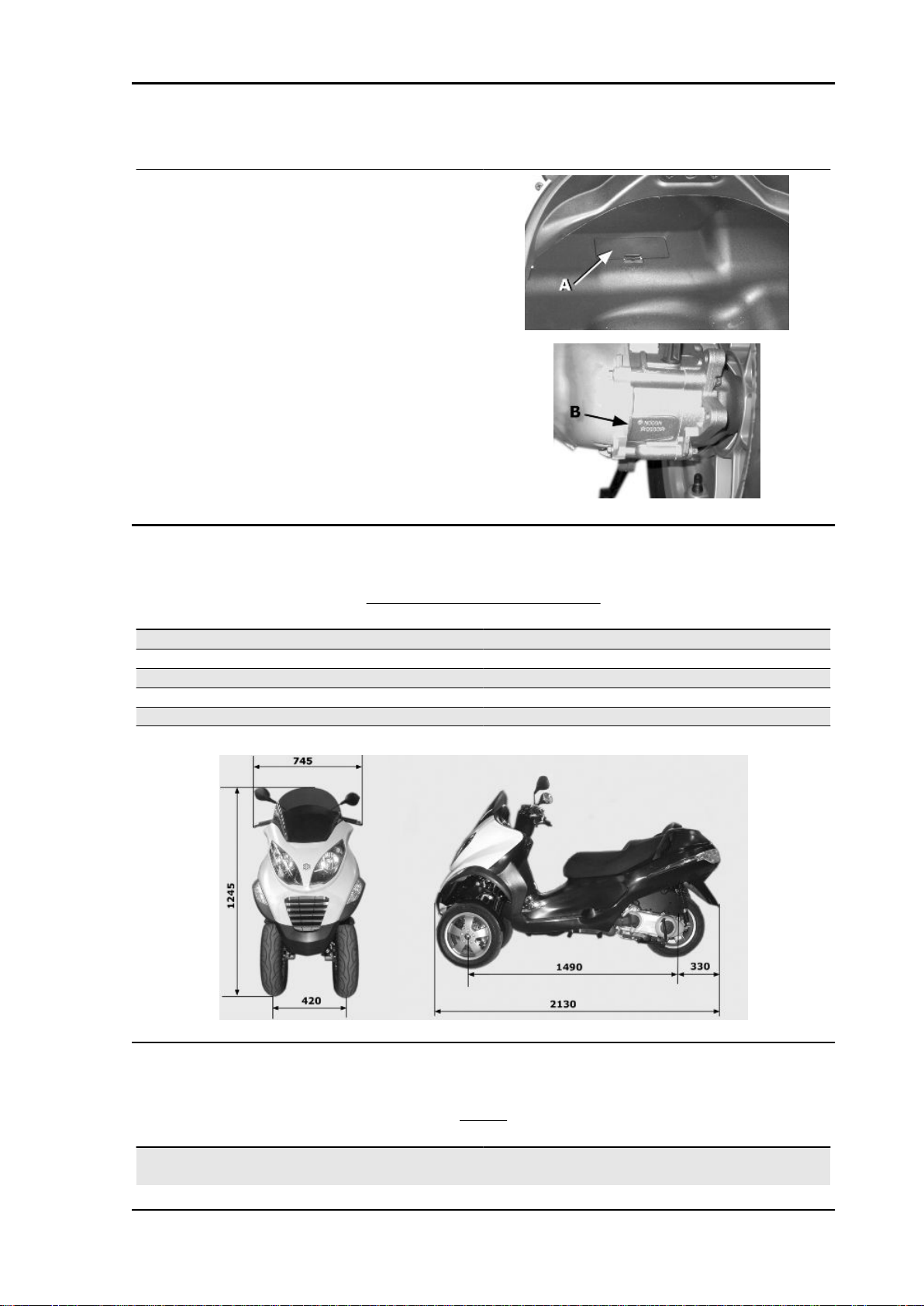
Dimensions and mass
Specification Desc./Quantity
Kerb weight 224 ± 5 Kg
Wheelbase 1490 mm
Height 1245 mm
Width (handlebar) 745 mm
Overall length 2130 mm
Track 420 mm
WEIGHTS AND DIMENSIONS
Engine
DATA
Specification Desc./Quantity
Type single-cylinder, four-stroke and four liquid-cooled
valves
CHAR - 3
Page 10

Characteristics MP3 250 i.e.
Specification Desc./Quantity
Timing system single overhead camshaft chain driven on the left-
hand side, three-arm rocking levers set up with
threaded set screw
Bore 72 mm
Stroke 60 mm
Cubic capacity 249.29 mm
Compression ratio 10.5 ÷ 11.5
Air filter sponge, impregnated with mixture (50% petrol and
50% oil)
Starting system electric starter motor with freewheel
Lubrication with lobe pump (inside the crankcase) chain-driv-
en and double filter: mesh and paper
Fuel supply by electronic injection with electric fuel pump
valve clearance intake: 0.10 mm - discharge: 0.15 mm
Engine idle speed approx. 1600 ÷ 1800 rpm
Max. speed 125 km/h
Transmission
Specification Desc./Quantity
Transmission Automatic expandable pulley variator with torque
Capacities
Specification Desc./Quantity
Engine oil approx. 1300 cc (recommended oil Selenia HI
Rear hub 250 cc ( recommended oil TUTELA MATRIX)
Fuel tank capacity Tank capacity: ~12 l (approximate value)
Fuel reserve approx. 2.5 litres (indicative value)
Cooling circuit Capacity: ~ 2.0 l
Electrical system
Specification Desc./Quantity
Ignition/advance Electronic, with inductive discharge and variable
Spark plug CHAMPION RG 4 PHP
Generator alternating current
TRANSMISSION
server, V belt, automatic clutch, gear reduction unit
and transmission housing with forced air circula-
tion cooling
CAPACITY
Scooter 4 Tech)
ELECTRICAL COMPONENTS
advance with three-dimensional mapping
Battery 12V-12Ah
CHAR - 4
Page 11

MP3 250 i.e. Characteristics
Frame and suspensions
FRAME AND SUSPENSIONS
Specification Desc./Quantity
Chassis Tubular and sheet steel.
Rear suspension Single arm with two double-acting hydraulic shock
absorbers and preloading adjustable to 4 posi-
tions.
Front suspension The tilt mechanism is composed of an articulated
parallelogram suspension with die-cast aluminium
control arms and two side headstocks plus shock
absorbers with hydraulic locking system.
Brakes
BRAKES
Specification Desc./Quantity
Front brake Ø 240 mm double disk with hydraulic control acti-
vated by the handlebar right-hand lever.
Rear brake Ø 240 mm disc brake with hydraulic control acti-
vated by the handlebar left-side lever.
Wheels and tyres
WHEELS AND TYRES
Specification Desc./Quantity
Front wheel Alloy rims: 12" x 3.00"
Rear wheel alloy rim: 12"x3,00
Front tyre 120/70-12", without inner tube
Rear tyre Without inner tube: 130/70-12" 62P
TYRE PRESSURE
Specification Desc./Quantity
Front tyre pressure (rider) Front tyre pressure (rider): 1.6 bar
Front tyre pressure (rider and passenger) Front tyre pressure (rider and passenger): 1.8 bar
Rear tyre pressure (rider) Rear tyre pressure (rider): 2 bar
Rear wheel pressure (rider and passenger): Rear tyre pressure (rider and passenger): 2.4 bar
N.B.
CHECK AND ADJUST TYRE PRESSURE WITH TYRES AT AMBIENT TEMPERATURE. REGULATE PRESSURE ACCORDING TO THE WEIGHT OF THE RIDER AND ACCESSORIES
Tightening Torques
STEERING
Name Torque in Nm
Steering lower ring nut (central headstock) 22 ÷ 27 loosen by 90°
Steering upper ring nut (central headstock) 27 ÷ 33
Handlebar fixing screw 50 ÷ 55
Fixing screws for handlebar control assembly U-
bolts
7 ÷ 10
CHAR - 5
Page 12

Characteristics MP3 250 i.e.
FRAME
Name Torque in Nm
Engine arm bolt - frame arm 33 ÷ 41
Swinging arm buffer nut 64 - 72
Engine-swinging arm bolt 55 ÷ 61
Frame-swinging arm bolt 55 ÷ 61
Centre stand bolt 31 ÷ 39
FRONT SUSPENSION
Name Torque in Nm
Shock absorber lower clamp 19 ÷ 26
Upper shock absorber clamp 19 ÷ 29
Front wheel fixing screws 19 ÷ 24
Steering arm bolt nut 20 ÷ 25
Tilt calliper fixing screws 20 ÷ 25
Front wheel shaft 74 ÷ 88
Arm coupling screws 45 ÷ 50
Screws fixing arms to side headstocks 45 ÷ 50
Screws fixing arms to central headstock 45 ÷ 50
Screws fixing the half-arm coupling flange 20 ÷ 25
Fixing screws for tilt locking disc section 20 ÷ 25
Side headstock upper ring nut 20 - 24
Side headstock lower ring nut 12 ÷ 15
Screw fixing sliding stem to shock absorber 45 ÷ 50
Clamp for sliding stem locking device 6.5 ÷ 10.5
Fixing nuts for constant-velocity universal joints 18 ÷ 20
Potentiometer to anti-tilting device clamp 8 ÷ 10
Electric motor to anti-tilting device clamp 11 ÷ 13
Clamp fixing pump bolt to anti-tilting device 11 ÷ 13
Pump to anti-tilting device clamp 11 ÷ 13
Pressure switch to distribution frame 18 ÷ 20
Sensor to tilt gripper clamp 2.5 ÷ 2.9
Pipe terminals to fifth wheel check spring 7 ÷ 11
Joint to anti-tilting device pump 20 ÷ 25
Lower fitting for shock absorber sliding locking
clamp pipes
Upper fitting for shock absorber sliding locking
clamp pipes
20 ÷ 25
20 ÷ 25
REAR SUSPENSION
Name Torque in Nm
Upper shock absorber clamp 33 ÷ 41
Shock absorber lower clamp 33 ÷ 41
Shock absorber-crankcase attachment bracket 20 ÷ 25
Rear wheel axle 104 ÷ 126
Muffler arm clamping screws 27 ÷ 30
FRONT BRAKE
Name Torque in Nm
Oil bleed screw 8÷12
Disc tightening screw (°) 5 - 6
Brake fluid pump - hose fitting 16 ÷ 20
Brake fluid pipe-calliper fitting 20 ÷ 25
CHAR - 6
Page 13

MP3 250 i.e. Characteristics
Name Torque in Nm
Screw tightening calliper to the support 20 ÷ 25
Calliper upper pipe fitting 20 ÷ 25
REAR BRAKE
Name Torque in Nm
Rear brake disc screws(°) 5 ÷ 6.5
Rear brake calliper-pipe fitting 20 ÷ 25
Rigid / flexible pipe fitting 13 ÷ 18
Rear brake pump-pipe fitting 16 ÷ 20
Rear brake calliper fixing screws 20 ÷ 25
REAR BRAKE
Product Description Specifications
(°) Loctite 243 Medium strength threadlock Apply LOCTITE 243 medium-
strength threadlock
MUFFLER
Name Torque in Nm
Muffler heat guard fixing screw 4 ÷ 5
Screw for fixing muffler to the support arm 20 ÷ 25
Lambda probe clamp on exhaust manifold 40 ÷ 50
Exhaust manifold-muffler joint clamp 12 ÷ 13
Manifold - muffler diaphragm tightening clamp 16 ÷ 18
LUBRICATION
Name Torque in Nm
Hub oil drainage plug 15 ÷ 17
Oil filter on crankcase fitting 27 ÷ 33
Engine oil drainage plug/mesh filter 24 ÷ 30
Oil filter 4 ÷ 6
Oil pump cover screws 7 ÷ 9
Screws fixing oil pump to the crankcase 5 - 6
Oil pump control crown screw 10 ÷ 14
Oil pump cover plate screws 4 ÷ 6
Oil sump screws 10 ÷ 14
Minimum oil pressure sensor 12 ÷ 14
CYLINDER HEAD
Name Torque in Nm
Spark plug 12 ÷ 14
Head cover screws 6 ÷ 7
Nuts fixing head to cylinder 7±1 + 10±1 + 270°
Head fixing side screws 11 ÷ 12 Nm
Starter ground screw 7 ÷ 8.5
Tappet set screw lock nut 6 ÷ 8
Inlet manifold screws 11 ÷ 13
Timing chain tensioner slider screw 10 ÷ 14
Starter ground support screw 11 ÷ 15
Timing chain tensioner support screw 11 ÷ 13
Timing chain tensioner central screw 5 - 6
Camshaft retention plate screw 4 ÷ 6
CHAR - 7
Page 14

Characteristics MP3 250 i.e.
TRANSMISSION
Name Torque in Nm
Belt support roller screw 11 ÷ 13
Clutch unit nut on driven pulley 45 ÷ 50
Drive pulley nut 75 ÷ 83
Transmission cover screws 11 ÷ 13
Driven pulley shaft nut 54 ÷ 60
Rear hub cap screws 24 ÷ 27
FLYWHEEL
Name Torque in Nm
Flywheel cover screw 11 ÷ 13
Stator assembly screws 3 - 4 (Apply LOCTITE 242 medium-strength
threadlock)
Flywheel nut 94 - 102 Nm
Pick-Up clamping screws 3 ÷ 4
Screw fixing freewheel to flywheel 13 ÷ 15
CRANKCASE AND CRANKSHAFT
Name Torque in Nm
Internal engine crankcase bulkhead (transmis-
sion-side half shaft) screws
Engine-crankcase coupling screws 11 ÷ 13
Starter motor screws 11 ÷ 13
Crankcase timing cover screws 3.5 - 4.5 (Apply LOCTITE 242 medium-strength
Name Torque in Nm
Water pump rotor cover 3 ÷ 4
Thermostat cover screws 3 ÷ 4
Bleed screw: 3
Overhaul data
Assembly clearances
4 ÷ 6
threadlock)
COOLING
CHAR - 8
Page 15
MP3 250 i.e. Characteristics
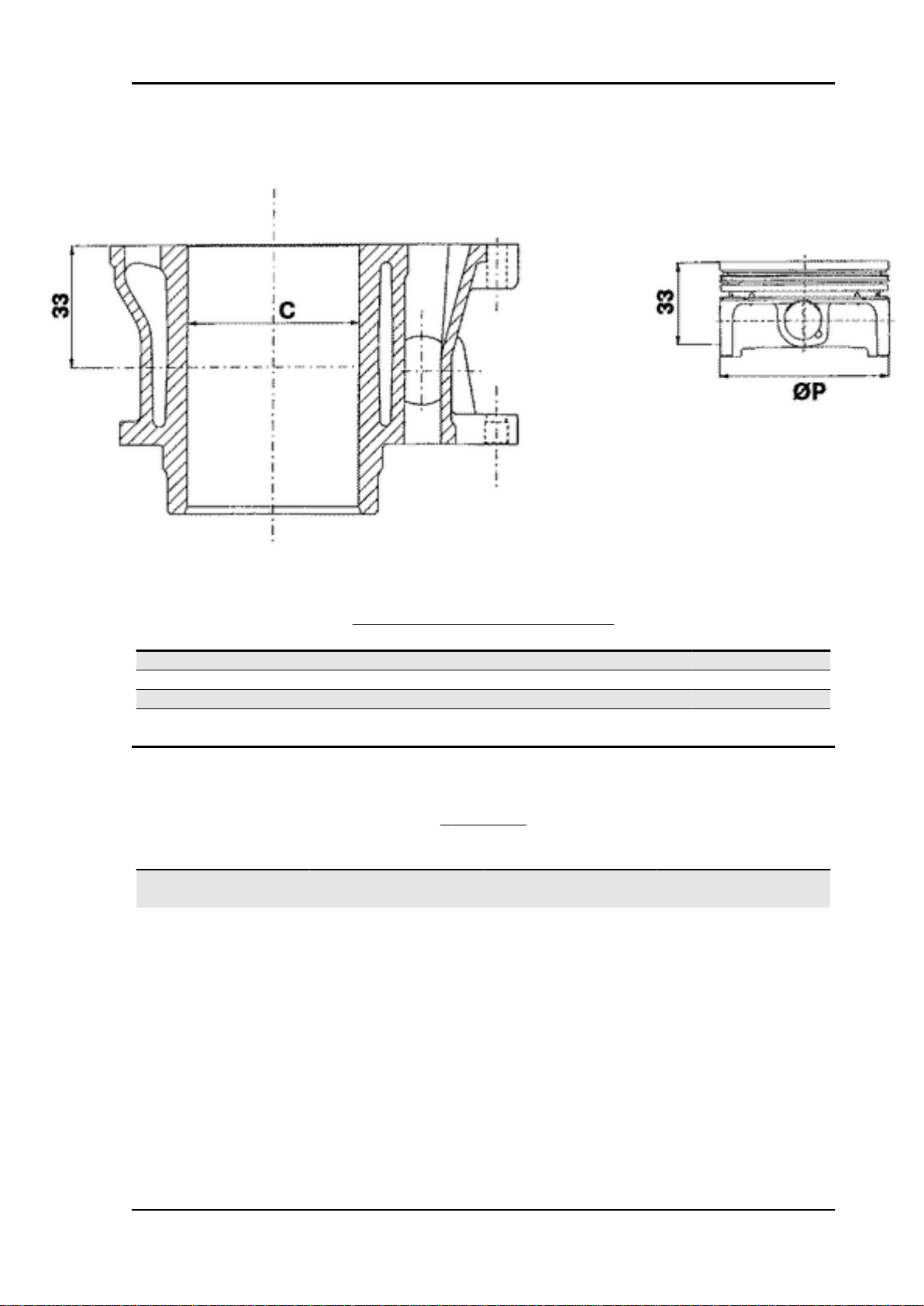
Cylinder - piston assy.
ENGINE COUPLING CATEGORY
Name Initials Cylinder Piston Play on fitting
Cylinder M 72.01 ÷ 72.017 71.953 ÷ 71.960 0.050 - 0.064
Cylinder N 72.017 ÷ 72.024 71.960 ÷ 71.967 0.050 - 0.064
Piston O 72.024 ÷ 72.031 71.967 ÷ 71.974 0.050 - 0.064
Piston P 72.031 ÷ 72.038 71.974 ÷ 71.981 0.050 - 0.064
Crankcase - crankshaft - connecting rod
CRANKSHAFT
Titolo Durata/Valore Testo Breve (< 4000
car.)
Crankshaft Crankshaft to crankcase
axial clearance
Crankshaft to crankcase axial clearance
Indirizzo Immagine
CHAR - 9
Page 16
Characteristics MP3 250 i.e.
CRANKSHAFT/ CRANKCASE AXIAL CLEARANCE
Name Description Dimensions Initials Quantity
Half-shaft, trans-
mission side
Flywheel-side half-
shaft
Connecting rod 18 -0.10 -0.15 C D = 0.20 - 0.50
Spacer tool 51.4 +0.05 E D = 0.20 - 0.50
16.6 +0-0.05 A D = 0.20 - 0.50
16.6 +0-0.05 B D = 0.20 - 0.50
Slot packing system
Characteristic
Compression ratio
10.5 ÷ 11.5 : 1
CHAR - 10
Page 17

MP3 250 i.e. Characteristics
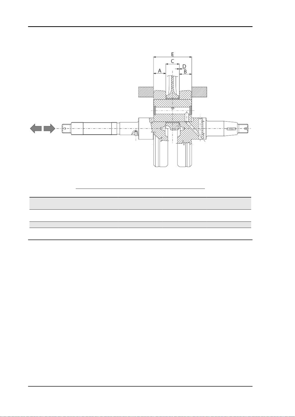
Measurement "A" to be taken is a value of piston re-entry, it indicates by how much the plane formed
by the piston crown falls below the plane formed by the top of the cylinder. The further the piston falls
inside the cylinder, the less the base gasket to be applied (to recover the compression ratio) and vice
versa.
N.B.
MEASUREMENT "A" MUST BE TAKEN WITHOUT ANY GASKET FITTED BETWEEN THE CRANKCASE AND CYLINDER AND AFTER RESETTING THE GAUGE, EQUIPPED WITH A SUPPORT, ON
A GROUND PLANE
ENGINE 250 SHIMMING
Name Measure A Thickness
shimming 3.70 - 3.60 0.4 ± 0.05
shimming 3.60 - 3.40 0.6 ± 0.05
shimming 3.40 - 3.30 0.8 ± 0.05
CHAR - 11
Page 18

Characteristics MP3 250 i.e.
Products
RECOMMENDED PRODUCTS TABLE
Product Description Specifications
AGIP ROTRA 80W-90 Rear hub oil SAE 80W/90 Oil that exceeds the
requirements of API GL3 specifi-
cations
AGIP CITY HI TEC 4T Oil to lubricate flexible transmis-
sions (throttle control)
AGIP FILTER OIL Oil for air filter sponge Mineral oil with specific additives
AGIP GP 330 Grease for brake levers, throttle White calcium complex soap-
AGIP CITY HI TEC 4T Engine oil SAE 5W-40, API SL, ACEA A3,
AGIP BRAKE 4 Brake fluid FMVSS DOT4 Synthetic fluid
SPECIAL AGIP PERMANENT
fluid
coolant Monoethylene glycol-based anti-
Oil for 4-stroke engines
for increased adhesiveness
based spray grease with NLGI 2;
ISO-L-XBCIB2
JASO MA Synthetic oil
freeze fluid, CUNA NC 956-16
CHAR - 12
Page 19

INDEX OF TOPICS
TOOLING TOOL
Page 20

Tooling MP3 250 i.e.
APPROPRIATE TOOL
Stores code Description
001330Y Tool for fitting steering seats
001467Y014 Pliers to extract ø 15-mm bear-
ings
005095Y Engine support
002465Y Pliers for circlips
006029Y Punch for fitting fifth wheel seat
on steering tube
020004Y Punch for removing fifth wheels
from headstock
020055Y Wrench for steering tube ring nut
TOOL - 2
Page 21
MP3 250 i.e. Tooling
Stores code Description
020074Y Support base for checking crank-
shaft alignment
020150Y Air heater support
020151Y Air heater
020193Y Oil pressure gauge
020262Y Crankcase splitting strip
020263Y Sheath for driven pulley fitting
TOOL - 3
Page 22
Tooling MP3 250 i.e.
Stores code Description
020306Y Punch for assembling valve seal
rings
020329Y MityVac vacuum-operated pump
020330Y Stroboscopic light for timing con-
trol
020331Y Digital multimeter
020332Y Digital rev counter
TOOL - 4
Page 23

MP3 250 i.e. Tooling
Stores code Description
020333Y Single battery charger
020334Y Multiple battery charger
020335Y Magnetic support for dial gauge
020357Y 32 x 35 mm adaptor
020359Y 42x47-mm adaptor
020360Y Adaptor 52 x 55 mm
TOOL - 5
Page 24

Tooling MP3 250 i.e.
Stores code Description
020363Y 20 mm guide
020375Y Adaptor 28 x 30 mm
020376Y Adaptor handle
020382Y Valve cotters equipped with part
012 removal tool
020382Y011 adapter for valve removal tool
TOOL - 6
Page 25
MP3 250 i.e. Tooling
Stores code Description
020393Y Piston fitting band
020412Y 15 mm guide
020423Y driven pulley lock wrench
020424Y Driven pulley roller casing fitting
punch
020426Y Piston fitting fork
TOOL - 7
Page 26
Tooling MP3 250 i.e.
Stores code Description
020431Y Valve oil seal extractor
020434Y Oil pressure control fitting
020444Y Tool for fitting/ removing the driv-
en pulley clutch
020456Y Ø 24 mm adaptor
020477Y Adaptor 37 mm
020483Y 30 mm guide
TOOL - 8
Page 27
MP3 250 i.e. Tooling
Stores code Description
020489Y Hub cover support stud bolt set
020428Y Piston position check support
020460Y Scooter diagnosis and tester
020621Y HV cable extraction adaptor
020481Y Control unit interface wiring
001467Y035 Belle for OD 47-mm bearings
TOOL - 9
Page 28

Tooling MP3 250 i.e.
Stores code Description
020626Y Driving pulley lock wrench
001467Y013 Pliers to extract ø 15-mm bear-
ings
020627Y Flywheel lock wrench
020467Y Flywheel extractor
020454Y Tool for fitting piston pin stops
(200 - 250)
020622Y Transmission-side oil guard
punch
TOOL - 10
Page 29
MP3 250 i.e. Tooling
Stores code Description
020480Y Petrol pressure check set
020244Y 15-mm diameter punch
020115Y Ø 18 punch
020271Y Tool for removing-fitting silent
bloc
020469Y Reprogramming kit for scooter
diagnosis tester
TOOL - 11
Page 30
Tooling MP3 250 i.e.
Stores code Description
020481Y004 Parking control unit interface wir-
ing
020639Y Tilt locking control unit software
020645Y MIU software updating with CAN
lines
001467Y017 Driver for OD 36 mm bearings
020234y extractor
020441Y 26 x 28 mm adaptor
TOOL - 12
Page 31

MP3 250 i.e. Tooling
Stores code Description
020362Y 12 mm guide
020358Y 37x40-mm adaptor
001467Y002 Driver for OD 73 mm bearing
TOOL - 13
Page 32

Tooling MP3 250 i.e.
TOOL - 14
Page 33

INDEX OF TOPICS
MAINTENANCE MAIN
Page 34

Maintenance MP3 250 i.e.
Follow these steps to reset the service icons:
1. With the key set to OFF, hold down the
"SET" button and turn the key to ON : the
"BELT" and "SERVICE" icons start flashing.
2. Push the "CLOCK" button for less than 1
second and the icons are displayed sequentially. The icon selected remains ON and the
other is no longer displayed.
3. Press the "CLOCK" button again for more
than 3 seconds to reset the relative maintenance step and the icon is no longer displayed.
Maintenance chart
EVERY 2 YEARS
60'
Coolant - change
Brake fluid - change
AFTER 1,000 KM
75'
Safety locks - check
Throttle lever - adjustment
Engine oil - change
Electrical system and battery - check
Coolant level - check
Brake fluid level - check
Engine oil - replacement
Brake pads - check condition and wear
Tyre pressure and wear - check
Vehicle and brake test - road test
Hub oil - change
Steering - Check
Tilt locking gripper control cable - adjustment
Action
Action
AFTER 5,000 KM, 15,000 KM, 25,000 KM, 35000 KM, 45,000 KM, 55,000 KM, 65,000 KM,
75,000 KM
10'
Action
Engine oil - level check/ top-up
Brake pads - check condition and wear
AFTER 10,000 KM 50,000 KM 70,000 KM
115'
MAIN - 2
Page 35

MP3 250 i.e. Maintenance
Action
Safety locks - check
Throttle lever - adjustment
Air filter - clean
Engine oil - change
Electrical system and battery - check
Coolant level - check
Brake fluid level - check
Engine oil - replacement
Brake pads - check condition and wear
Sliding block / variable speed rollers - change
Tyre pressure and wear - check
Vehicle and brake test - road test
Hub oil - check
Suspensions - check
Steering - Check
Centre stand - lubrication
Tilt locking gripper control cable - adjustment
AFTER 20,000 KM, 35,000 KM, 50,000 KM, 65,000 KM, 80,000 KM
35'
Action
Driving Belt - replacement
AFTER 20,000 KM, 40,000 KM, 80,000 KM
165'
Spark plug - replacement
Throttle lever - adjustment
Air filter - clean
Engine oil - change
Valve clearance - check
Electrical system and battery - check
Coolant level - check
Brake fluid level - check
Engine oil - replacement
Brake pads - check condition and wear
Sliding block / variable speed rollers - change
Tyre pressure and wear - check
Vehicle and brake test - road test
Hub oil - change
Suspensions - check
Steering - Check
Tilt locking gripper control cable - adjustment
155'
Safety locks - check
Throttle lever - adjustment
Air filter - clean
Engine oil - change
Electrical system and battery - check
Action
30,000 KM
Action
MAIN - 3
Page 36

Maintenance MP3 250 i.e.
Action
Coolant level - check
Brake fluid level - check
Engine oil - replacement
Hub oil - check
Brake pads - check condition and wear
Sliding block / variable speed rollers - change
Tyre pressure and wear - check
Vehicle and brake test - road test
Suspensions - check
Steering - Check
Tilt locking gripper control cable - adjustment
60,000 KM
205'
Action
Spark plug - replacement
Throttle lever - adjustment
Air filter - clean
Engine oil - change
Valve clearance - check
Electrical system and battery - check
Coolant level - check
Brake fluid level - check
Engine oil - replacement
Hub oil - change
Brake pads - check condition and wear
Sliding block / variable speed rollers - change
Tyre pressure and wear - check
Vehicle and brake test - road test
Suspensions - check
Steering - Check
Tilt locking gripper control cable - adjustment
Checking the spark advance
The ignition advance is determined electronically
on the basis of parameters known by the control
unit. For this reason it is not possible to declare the
reference values based on the engine rpm. The
ignition timing value is detectable any time using
the diagnostic tester. It is possible to check whether the ignition advance determined by the system
does in fact correspond with the value actually activated on the engine, by means of the stroboscopic light.
Proceed as follows:
- Remove the spark plug.
MAIN - 4
Page 37

MP3 250 i.e. Maintenance
- Remove the transmission crankcase.
- Rotate the driving pulley fan until the reference
marks between the flywheel and flywheel cover
coincide as shown in the photograph.
- Bring the reference mark onto the transmission
side between the fan and the transmission cover
as shown in the photograph.
- Refit the spark plug.
- Refit the plastic cap on the flywheel cover.
- Adjust the spark gap to the contact position (no
reference mark visible) and install it on engine between the spark plug and spark plug cap
- Connect the induction calliper on the spark gap
cable respecting the proper polarity (the arrow on
the calliper must be pointing at the spark plug).
- Connect the diagnostic tester.
- Start the engine.
- Select the «parameter» function in this menu.
- Select the stroboscopic light command in the traditional four-stroke engine position (1 spark 2
revs).
- Check that the real values of rpm and ignition
advance match those measured using the diagnostic tester.
If the values do not correspond, check:
- distribution timing
- revolution-timing sensor
- Injection control unit
Specific tooling
020460Y Scooter diagnosis and tester
020330Y Stroboscopic light for timing control
020621Y HV cable extraction adaptor
MAIN - 5
Page 38

Maintenance MP3 250 i.e.
Spark plug
Remove the port on the right-hand side panel of
the vehicle by undoing the clamping screw and
using a small screwdriver in the rear recess shown
in the figure, then do the following :
1. Disconnect spark plug HV wire cap "A";
2. Unscrew the spark plug using the wrench sup-
plied. ;
3. When refitting, place the spark plug in the hole
at the due inclination and tighten it by hand until it
is finger tight;
4. Only use the wrench to lock it in place;
5. Place hood«A» fully over the spark plug.
6. Refit the port making sure the rear hook is in-
serted.
WARNING
THE SPARK PLUG MUST BE REMOVED WHEN
THE ENGINE IS COLD. THE SPARK PLUG
MUST BE REPLACED EVERY 20,000 KM. USE
OF ELECTRONIC CONTROL UNITS OR ELECTRONIC IGNITIONS DIFFERING FROM THOSE
RECOMMENDED CAN SERIOUSLY DAMAGE
THE ENGINE.
N.B.
THE USE OF SPARK PLUGS OTHER THAN
THE INDICATED TYPE OR OF SHIELDLESS
SPARK PLUG CAPS CAN CAUSE ELECTRICAL SYSTEM FAILURES.
Electric characteristic
Spark plug
MAIN - 6
Page 39

MP3 250 i.e. Maintenance
CHAMPION RG4 PHP
Electrode gap
0.7 ÷ 0.8 mm
Hub oil
Check
- Park the vehicle on its centre stand on flat
ground;
- Remove the oil dipstick «A», dry it with a clean
cloth and put it back into its hole tightening it
completely;
Remove the dipstick and check that the oil level is
slightly over the second notch starting from the
lower end; if the level is under the MAX. mark, it
needs to be filled with the right amount of hub oil.
-Screw up the oil dipstick again and make sure it
is locked properly into place.
Replacement
-Remove the oil cap «A».
- Unscrew the oil drainage cap "B" and drain out
all the oil.
- Screw in the drainage cap again and fill the hub
with the prescribed oil.
Recommended products
AGIP ROTRA 80W-90 Rear hub oil
SAE 80W/90 Oil that exceeds the requirements of
API GL3 specifications
Characteristic
Rear hub oil
Capacity approximately 250 cc
Locking torques (N*m)
Hub oil drainage screw 15 ÷ 17 Nm
MAIN - 7
Page 40

Maintenance MP3 250 i.e.
Air filter
Proceed as follows:
Undo the clamping screws «A» (two of which are
on the knob-type head) and remove the air-box
cover.
1. Wash the sponge with water and neutral soap.
2. Dry it with a clean cloth and small blasts of compressed air.
3. Impregnate the sponge with a mixture of 50% petrol and 50% specified oil.
4. Gently squeeze the filter element, let it drip and then refit it.
CAUTION
IF THE VEHICLE IS USED ON DUSTY ROADS IT IS NECESSARY TO CARRY OUT MAINTENANCE
CONTROLS OF THE AIR FILTER TO AVOID DAMAGING THE ENGINE.
Recommended products
AGIP FILTER OIL Oil for air filter sponge
Mineral oil with specific additives for increased adhesiveness
Engine oil
In 4T engines, the engine oil is used to lubricate the distribution elements, the bench bearings and the
thermal group. An insufficient quantity of oil can cause serious damage to the engine.
In all 4T engines, the deterioration of the oil characteristics, or a certain consumption should be considered normal, especially if during the run-in period. Consumption levels in particular can be influenced
by the conditions of use (e.g.: oil consumption increases when driving at "full throttle".
Replacement
At 1,000 km and after every 10,000 km, the oil and
the filter must be changed. The engine must be
drained by running off the oil from drainage cap
"B" of the flywheel side gauze pre-filter; furthermore to facilitate oil drainage, loosen the cap/
dipstick "A". Once all the oil has drained through
the drainage hole, unscrew the oil cartridge filter
"C" and remove it.
MAIN - 8
Page 41

MP3 250 i.e. Maintenance
Make sure the pre-filter and discharge tap O-rings
are in good condition.
Lubricate them and refit the gauze filter and oil
drainage tap, screwing them up to the specified
torque.
Refit the new cartridge filter being careful to lubricate the O-ring before fitting it.
Change the engine oil.
Since a certain quantity of oil still remains in the
circuit, oil must be filled from cap "A". Then start
up the scooter, leave it running for a few minutes
and switch it off: after five minutes check the level
and if necessary top up without exceeding the
MAX level. The cartridge filter must be replaced
every time the oil is changed. Use new oil of the
recommended type for topping up and changing
purposes.
N.B.
THE ENGINE MUST BE HOT WHEN THE OIL IS
CHANGED.
Recommended products
AGIP CITY HI TEC 4T Engine oil
SAE 5W-40 Synthetic oil that exceed the requirements of API SL, ACEA A3, JASO MA specifications
Check
This operation must be carried out with the engine
cold and following the procedure below:
1. Place the vehicle on its centre stand and on
flat ground.
2. Undo cap/dipstick "A", dry it off with a clean
cloth and replace it, screwing down com-
pletely.
3. Remove the cap/dipstick again and check
that the level is between the min and max.
marks; top up if necessary.
MAIN - 9
Page 42

Maintenance MP3 250 i.e.
The MAX level mark indicates a quantity of around
1300 cc of engine oil. If the check is carried out
after the vehicle has been used, and therefore with
a hot engine, the level line will be lower; in order
to carry out a correct check it is necessary to wait
at least 10 minutes after the engine has been stopped, so as to get the correct level.
Oil top up
The oil should be topped up after having checked the level and in any case by adding oil without ever
exceeding the MAX. level.
Restoration of the level from MIN to MAX requires approximately 200 cc.
Engine oil filter
The cartridge filter must be replaced every time the oil is changed. Use new oil of the recommended
type for topping up and changing purposes.
Make sure the pre-filter and drainage plug O-rings are in good conditions. Lubricate them and refit the
mesh filter and oil drainage plug, screwing them up to the specified torque. Refit the new cartridge filter
being careful to lubricate the O-ring before the fitting. Change the engine oil.
Recommended products
AGIP CITY HI TEC 4T Engine oil
SAE 5W-40 Synthetic oil that exceed the requirements of API SL, ACEA A3, JASO MA specifications
Oil pressure warning light
The vehicle is equipped with a warning light on the
instrument panel that lights up when the key is
turned to the «ON» position. However, this light
should switch off once the engine has been started.
If the light turns on during braking, at idling
speed or while turning a corner, it is necessary
to check the oil level and the lubrication system.
MAIN - 10
Page 43

MP3 250 i.e. Maintenance
Checking the ignition timing
-Remove the plastic cap on the flywheel cover
-Turn the flywheel until the reference mark «T» on
the rotor matches the reference mark on the flywheel cover as shown in the figure (TDC). Make
sure that the 4V reference point on the camshaft
control pulley is aligned with the reference point on
the head as shown in the second figure. If the reference is opposite the indicator on the head, turn
the crankshaft once more.
For the use of this reference mark, remove the
spark plug and turn the engine in the direction that
is the reverse of the normal direction using a calliper spanner applied to the camshaft command
pulley casing.
Cooling system
Introduction of the engine coolant.
The fluid level must checked every 10,000 kilometres with a cold engine, in the way shown below:
Place the scooter on its centre stand and on flat
ground.
- Undo the screw shown in the figure and remove
the expansion tank cap on RHS.
- Top up if the fluid level is near or below the MIN
level edge. The liquid level must always be between the MIN and MAX level.
-The coolant consists of an ethylene glycol and
corrosion inhibitor based 50% demineralised water- antifreeze solution mix.
CAUTION
DO NOT EXCEED THE MAX. LEVEL WHEN
FILLING SO AS TO AVOID THE COOLANT ESCAPING FROM THE EXPANSION TANK WHEN
THE vehicle IS IN USE.
MAIN - 11
Page 44

Maintenance MP3 250 i.e.
Braking system
Level check
The front and rear brake fluid reservoirs are both
positioned on the handlebars. Proceed as follows:
- Rest the vehicle on its centre stand with the handlebars perfectly horizontal;
- Check the fluid level through the sight glass
«C». A certain lowering of the level is caused by
wear on the pads.
Top-up
Proceed as follows: Loosen the screw "B" and lift
the plastic cover "A" in order to access the brake
fluid reservoir. Loosen the two fixing screws and
remove the reservoir cover; top-up with the recommended fluid without exceeding the 'MAX.'
mark.
This procedure applies to the rear brake pump topup operation; follow the same procedure for the
front brake pump.
Under normal climatic conditions, the fluid must be
changed every 20,000 km or anyway every two
years.
WARNING
ONLY USE DOT 4 CLASS BRAKE FLUIDS.
COOLING SYSTEM FLUIDS ARE HIGHLY CORROSIVE. MAKE SURE THAT IT DOES NOT
COME INTO CONTACT WITH THE PAINTWORK.
CAUTION
MAKE SURE THE BRAKE FLUID DOES NOT
GET INTO YOUR EYES OR ON YOUR SKIN OR
CLOTHES. IF THIS HAPPENS ACCIDENTALLY,
WASH WITH WATER.
MAIN - 12
Page 45

MP3 250 i.e. Maintenance
Headlight adjustment
Proceed as follows:
1. Position the unloaded vehicle, in running order
and with the tyres inflated to the prescribed pressure, on a flat surface 10 m away from a half-lit
white screen; ensure that the longitudinal axis of
the vehicle is perpendicular to the screen;
2. Remove the headlight assembly central cover
3. Turn on the headlight and check that the limit of
the projected light beam is not over 9/10 or below
7/10 of the distance from the ground to the centre
of the vehicle headlight;
4. Otherwise, adjust the headlight with the
screws«A» indicated in the figure
N.B.
THE ABOVE PROCEDURE COMPLIES WITH
THE EUROPEAN STANDARDS REGARDING
MAXIMUM AND MINIMUM HEIGHT OF LIGHT
BEAMS. REFER TO THE STATUTORY REGULATIONS IN FORCE IN EVERY COUNTRY
WHERE THE vehicle IS USED.
MAIN - 13
Page 46

Maintenance MP3 250 i.e.
MAIN - 14
Page 47

INDEX OF TOPICS
TROUBLESHOOTING TROUBL
Page 48

Troubleshooting MP3 250 i.e.
This section makes it possible to find what solutions to apply when troubleshooting.
For each breakdown, a list of the possible causes and respective interventions is given.
Engine
Excessive oil consumption/Exhaust smoke
EXCESSIVE CONSUMPTION
Possible Cause Operation
Wrong valve adjustment Adjust the valve clearance properly
Overheated valves Remove the head and the valves, grind or replace
the valves
Misshapen/worn valve seats Replace the head assembly
Worn cylinder, Worn or broken piston rings Replace the piston cylinder assembly or piston
rings
Worn or broken piston rings or piston rings that
have not been fitted properly
Oil leaks from the couplings or from the gaskets Check and replace the gaskets or restore the cou-
Worn valve oil guard Replace the valve oil guard
Worn valve guides Check and replace the head unit if required
Replace the piston cylinder unit or just the piston
rings
pling seal
Insufficient lubrication pressure
POOR LUBRICATION PRESSURE
Possible Cause Operation
By-Pass remains open Check the By-Pass and replace if required. Care-
Oil pump with excessive clearance Perform the dimensional checks on the oil pump
Oil filter too dirty Replace the cartridge filter
Oil level too low Restore the level using the recommended oil type
Transmission and brakes
Clutch grabbing or performing inadequately
IRREGULAR CLUTCH PERFORMANCE OR SLIPPAGE
Possible Cause Operation
Faulty clutch Check that there is no grease on the masses.
Check that the clutch mass contact surface with
the casing is mainly in the centre with equivalent
characteristics on the three masses. Check that
the clutch casing is not scored or worn in an anom-
fully clean the By-Pass area.
components
(Selenia HI Scooter 4 Tech)
alous way
TROUBL - 2
Page 49

MP3 250 i.e. Troubleshooting
Insufficient braking
INEFFICIENT BRAKING SYSTEM
Possible Cause Operation
Inefficient braking system Check the pad wear (1.5 min). Check that the
brake discs are not worn, scored or warped. Check
the correct level of fluid in the pumps and replace
brake fluid if necessary. Check there is no air in
the circuits; if necessary, bleed the air. Check that
the front brake calliper moves in axis with the disc.
Fluid leakage in hydraulic braking system Failing elastic fittings, plunger or brake pump
seals, replace
Brake disc slack or distorted Check the brake disc screws are locked; measure
the axial shift of the disc with a dial gauge and with
wheel mounted on the scooter.
Brakes overheating
BRAKES OVERHEATING
Possible Cause Operation
Defective sliding of pistons Check calliper and replace any damaged part.
Brake disc slack or distorted Check the brake disc screws are locked; use a dial
gauge and a wheel mounted on the vehicle to
measure the axial shift of the disc.
Clogged compensation holes on the pump Clean carefully and blast with compressed air
Swollen or glued rubber gaskets Replace gaskets.
Steering and suspensions
Heavy steering
STEERING HARDENING
Possible Cause Operation
Steering hardening Check the tightening of the top and bottom ring
nuts. If irregularities continue in turning the steer-
ing even after making the above adjustments,
check the seats in which the ball bearings rotate:
if they are recessed or if the balls are squashed,
replace them.
Excessive steering play
EXCESSIVE STEERING CLEARANCE
Possible Cause Operation
Torque not conforming Check the tightening of the top and bottom ring
nuts. If irregularities continue in turning the steer-
ing even after making the above adjustments,
check the seats in which the ball bearings rotate:
TROUBL - 3
Page 50

Troubleshooting MP3 250 i.e.
Possible Cause Operation
if they are recessed or if the balls are squashed,
replace them.
Noisy suspension
NOISY SUSPENSION
Possible Cause Operation
Malfunctions in the suspension system If the front suspension is noisy, check: the efficien-
cy of the front shock absorbers; the condition of
the ball bearings and relevant lock-nuts, the limit
switch rubber buffers and the movement bushings.
In conclusion, check the tightening torque of the
wheel hub, the brake calliper, the shock absorber
disk in the attachment to the hub and the steering
tube.
Suspension oil leakage
OIL LEAKAGE FROM SUSPENSION
Possible Cause Operation
Seal fault or breakage Replace the shock absorber Check the condition
of wear of the steering covers and the adjust-
ments.
TROUBL - 4
Page 51

INDEX OF TOPICS
ELECTRICAL SYSTEM ELE SYS
Page 52

Electrical system MP3 250 i.e.
KEY
1. Immobilizer aerial
2. Injection ECU
3. Engine rev sensor
4. Magneto flywheel
5. Diagnostics socket
6. Voltage regulator
7. Key switch
8. Fuse-box
9. Fuse-box
10. Battery
11. Starter motor
12. Start up remote control switch
13. Starter button
14. Stop button on front brake
15. Stop button on rear brake
16. Helmet compartment light switch
17. Helmet compartment light switch
18. Helmet compartment light bulb
19. Saddle opener actuator
20. Saddle opening receiver
ELE SYS - 2
Page 53

MP3 250 i.e. Electrical system
21. Preparation for anti-theft device
22. Turn indicator switch
23. Hazard switch
24. Turn indicator control device
25. Left rear turn indicator bulbs
26. Rear headlight assembly
A. Tail light
C. Stop light
27. License plate bulb
28. Right rear turn indicator bulbs
29. Left front turn indicator bulb
30. Front headlight assembly
A. Low-beam light bulb
B. Tail light
C. High-beam light bulb
31. Right front turn indicator bulb
32. Light switch
33. Remote control headlight
34. Horn remote control
35. Horn
36. Horn button
37. Pressure sensor
38. Locking/unlocking switch
39. Geared motor
40. Right tone wheel
41. Left tone wheel
42. Brake calliper sensor
43. Parking electronic control unit
44. Oil pressure sensor
45. Hand brake
46. Rider presence sensor
47. Potentiometer
48. Instrument panel
49. External temperature sensor
50. Fuel level transmitter
51. Electric fan
52. Remote control for electric fan
53. Injection load remote control
ELE SYS - 3
Page 54

Electrical system MP3 250 i.e.
54. Engine stop switch
55. Mode button
56. Engine temperature sensor
57. Fuel pump
58. Fuel injector
59. Lambda probe
60. Spark plug
61. High voltage coil
Key
Ar: Orange Az: Sky blue Bi: White Bl: Blue Gi: Yellow Gr:Grey
Ma:Brown Ne: Black Ro: Pink Rs: Red Ve: Green Vi: Purple
Electrical system installation
ELE SYS - 4
Page 55

MP3 250 i.e. Electrical system
ELE SYS - 5
Page 56

Electrical system MP3 250 i.e.
ELE SYS - 6
Page 57

MP3 250 i.e. Electrical system
ELE SYS - 7
Page 58

Electrical system MP3 250 i.e.
ELE SYS - 8
Page 59

MP3 250 i.e. Electrical system
ELE SYS - 9
Page 60

Electrical system MP3 250 i.e.
Conceptual diagrams
Ignition
KEY
1. Immobilizer aerial
2. Injection ECU
3. Revolution sensor
7. Key switch
8. Fuse-box
9. Fuse-box
10. Battery
ELE SYS - 10
Page 61

MP3 250 i.e. Electrical system
53. Injection load remote control
60. Spark plug
61. High voltage coil
Battery recharge and starting
KEY
2. Injection ECU
4. Magneto flywheel
6. Voltage regulator
7. Key switch
8. Fuse-box
9. Fuse-box
10. Battery
11. Starter motor
12. Start up remote control switch
13. Starter button
14. Stop button on front brake
15. Stop button on rear brake
26. Rear headlight assembly
B. Stop light
54. Engine stop switch
ELE SYS - 11
Page 62

Electrical system MP3 250 i.e.
Level indicators and enable signals section
KEY
1. Immobilizer aerial
2. Injection ECU
3. Revolution sensor
7. Key switch
8. Fuse-box
9. Fuse-box
10. Battery
38. Locking/unlocking switch
39. Geared motor
40. Right tone wheel
41. Left tone wheel
42. Brake calliper sensor
43. Parking electronic control unit
44. Oil pressure sensor
45. Hand brake
46. Rider presence sensor
47. Potentiometer
48. Instrument panel
ELE SYS - 12
Page 63

MP3 250 i.e. Electrical system
49. External temperature sensor
50. Fuel level transmitter
53. Injection load remote control
54. Engine stop switch
55. Mode button
56. Engine temperature sensor
57. Fuel pump
58. Fuel injector
59. Lambda probe
Devices and accessories
KEY
2. Injection ECU
7. Key switch
8. Fuse-box
9. Fuse-box
10. Battery
19. Saddle opening actuator
20. Saddle opening receiver
21. Wiring for antitheft device
34. Horn remote control
ELE SYS - 13
Page 64

Electrical system MP3 250 i.e.
35. Horn
36. Horn button
37. Pressure sensor
43. Parking electronic control unit
51. Electric fan
52. Remote control for electric fan
Lights and turn indicators
KEY
7. Key switch
8. Fuse-box
9. Fuse-box
10. Battery
21. Wiring for antitheft device
22. Turn indicator switch
23. Hazard switch
24. Turn indicator control device
25. Left rear turn indicator bulbs
26. Rear headlight assembly
A. Tail light
B. Stop light
ELE SYS - 14
Page 65

MP3 250 i.e. Electrical system
27. License plate bulb
28. Right rear turn indicator bulbs
29. Left front turn indicator bulb
30. Front headlight assembly
A. Low-beam light bulb
B. Tail light
C. High-beam light bulb
31. Right front turn indicator bulb
32. Light switch
33. Remote control headlight
43. Parking electronic control unit
48. Instrument panel
Checks and inspections
This section is devoted to the checks on the electrical system components.
Immobiliser
The electronic ignition system is controlled by the
control unit with the integrated Immobilizer system. The immobilizer is an anti-theft system that
allows the scooter to be operated only when it is
started with coded keys recognised by the control
unit. The code is integrated in a transponder in the
key block. This allows the driver clear operation
without having to do anything other than just turning the key. The Immobiliser system consists of the
following components:
- Electronic control unit
- Immobilizer aerial
- Master key with incorporated transponder (red
key)
- service key with incorporated transponder (black
key)
- H.V. coil
- Diagnostic LED
The diagnostic LED also works as a deterring
blinker. This function is activated every time the
ELE SYS - 15
Page 66

Electrical system MP3 250 i.e.
ignition switch is turned to the "OFF" position, or
the emergency stop switch is turned to the "OFF"
position. It remains activated for 48 hours in order
not to affect the battery charge. When the ignition
switch is turned to the "ON" position, the deterring
blinker function is deactivated. Subsequently, a
flash confirms the switching to the "ON" status.
The duration of the flash depends on the programming of the electronic control unit If the LED is off
regardless of the position of the ignition-key switch
and/or the instrument panel is not initiated, check:
•
there is battery voltage
•
fuses 6,7,10 are in working order
•
there is power to the control unit as
specified below:
Remove the connector support bracket shown in
the photograph and disconnect the connector from
the control unit. Check the following conditions:
With the key switch set to OFF:
•
if there is battery voltage between terminals 6-26 and terminal 6-chassis
ground (fixed power supply). If there is
no voltage check that fuse 6 and its cable are in working order.
With the key switch in the OFF position:
•
there is battery voltage between terminals 5-26 and terminal 5-frame earth
ELE SYS - 16
(fixed power supply). If there is no voltage, check the key switch contacts,
that fuse no. 10 and its cable are working order.
Page 67

MP3 250 i.e. Electrical system
•
There is continuity between terminals
12-18 and 12-19 with the emergency
cut-out switch in the RUN position. If
there is no continuity check the contacts of the latter.
If no faults are found, replace the electronic control
unit.
After removing the shield back plate, remove the
electrical connection from the aerial as shown in
the photograph
Remove the protective base from the connector.
With the ignition key switch at ON check there is
battery voltage between the Red-White and Black
cables
ELE SYS - 17
Page 68

Electrical system MP3 250 i.e.
With MIU connector disconnected check the continuity between the Orange-White cable and pin 7
of the interface wiring .
Specific tooling
020481Y Control unit interface wiring
020331Y Digital multimeter
Virgin circuit
When the ignition system is not encrypted, any key will start the engine but limited to 2000 rpm. The
keys can only be recognised if the control unit has been programmed properly. The data storage procedure for a previously not programmed control unit provides for the recognition of the master as the
first key to be stored to memory: this becomes particularly important because it is the only key that
enables the control unit to be wiped clean and reprogrammed for the memorisation of the service keys.
The master and service keys must be used to code the system as follows:
- Insert the Master key, turn it to «ON» and keep this position for two seconds (lower and upper limits
1 to 3 seconds).
- Insert the service key and turn it to "ON" for 2 seconds.
- If you have copies of the key, repeat the operation with each key.
- Insert the MASTER key again and turn it to "ON" for 2 seconds.
The maximum time to change keys is 10 seconds.
During a single data storage sequence a maximum of 7 service keys are allowed.
It is essential to adhere to the times and the procedure. If you do not, start again from the beginning.
Once the system has been programmed, master key transponder, decoder and control unit are strictly
matched. With this link established, it is now possible to encode new service keys, in the event of losses,
replacements, etc. Each new programming deletes the previous one so, in order to add or eliminate
keys, you must repeat the procedure using all the keys you intend to keep using. If a service key should
become un-coded, the efficiency of the high voltage circuit shielding must be thoroughly inspected: In
any case it is advisable to use resistive spark plugs.
ELE SYS - 18
Page 69

MP3 250 i.e. Electrical system
Characteristic
MASTER key:
RED KEY
SERVICE key.
BLACK KEY
Diagnostic codes
The immobiliser system is tested each time the ignition-key switch is turned from OFF to ON. During
this diagnosis phase a number of control unit statuses can be seen and various light codes displayed. Regardless of the code transmitted, if at
the end of the diagnosis the led remains off permanently, the ignition is enabled. If, however, the
led remains on permanently, it means the ignition
is inhibited:
1. Previously unused control unit - key inserted: a single 2 second flash is displayed, after
which the LED remains off permanently. The keys
can be stored to memory, the vehicle can be started but with a limitation imposed on the number of
revs.
2. Previously unused control unit - transponder absent or cannot be used: The LED is per-
manently ON; in this condition, no operations are
possible, including starting of the vehicle.
3. Programmed control unit - the service key in
(normal condition of use): a single 0.7 second
flash is displayed, after which the LED remains off
permanently. The engine can be started.
4. Programmed control unit - Master key in: a
0.7 sec. flash is displayed followed by the LED remaining off for 2 sec. and then by short 0.46 sec.
flashes the same number of times as there are
keys stored in the memory including the Master
key. When the diagnosis has been completed, the
ELE SYS - 19
Page 70

Electrical system MP3 250 i.e.
LED remains permanently OFF. The engine can
be started.
5. Programmed control unit - fault detected: a light code is displayed according to the fault detected,
after which the LED remains on permanently. The engine cannot be started. The codes that can be
transmitted are:
•
Code 1 flash
•
2 flash code
•
3 flash code
Diagnostic code - 1 flash
The one-flash code indicates a system where the
serial line is not present or is not detected. Check
the Immobiliser aerial wiring and change it if necessary.
Diagnostic code - 2 flashes
Two-flash code shows a system where the control
unit does not show the transponder signal. This
might depend on the inefficiency of the immobiliser
aerial or the transponder.
Turn the switch to ON using several keys: if the
code is repeated even with the Master key, check
the aerial wiring and change it if necessary. If this
is not the case, replace the defective key and/or
reprogram the control unit. Replace the control unit
if the problem continues.
ELE SYS - 20
Page 71

MP3 250 i.e. Electrical system
Diagnostic code - 3 flashes
The three-flash code indicates a system where the
control unit does not recognise the key. Turn the
switch to ON using several keys: if the error code
is repeated even with the Master key, replace the
control unit. If this is not the case, perform a reprogramming.
Battery recharge circuit
The recharge system is provided with a three-phase alternator with permanent magneto flywheel.
The alternator is directly connected to the voltage regulator.
This, in its turn, is connected directly to the ground and the battery positive terminal passing through
the 30A protective fuse.
The three- phase generator provides good recharge power and at low revs, a good compromise is
achieved between generated power and idle stability.
Stator check
Stator winding check-up
WARNING
THE CHECK-UP CAN BE MADE WITH THE STATOR PROPERLY INSTALLED.
1 Remove the right side panel.
2) Disconnect the connector between stator and regulator with the three yellow cables as shown in the
photograph.
3) Measure the resistance between each of the yellow terminals and the other two.
Electric characteristic
Resistance:
0.2 - 1 Ω
ELE SYS - 21
Page 72

Electrical system MP3 250 i.e.
4) Check that there is insulation between the each
yellow cable and the ground.
5) If values are incorrect, replace the stator.
Recharge system voltage check
Look for any leakage
1) Access the battery by removing its cover under the saddle.
2) Check that the battery does not show signs of losing fluid before checking the output voltage.
3) Turn the ignition key to position OFF, connect the terminals of the tester between the negative pole
(-) of the battery and the black cable and only then disconnect the black cable from the negative pole
(-) of the battery.
4) With ignition key still at OFF, the reading detected by the ammeter must be ≤ 0.5 mA.
Check the charging current
WARNING
BEFORE CARRYING OUT THE CHECK, MAKE SURE THAT THE BATTERY IS IN GOOD WORKING ORDER.
1) Place the vehicle on its centre stand
2) With the battery correctly connected to the circuit, place the tester terminals between the battery
terminals..
3) Turn on the engine, increase the revs and, at the same time, measure the voltage.
Electric characteristic
Voltage ranging between 14.0 and 15.0V at 5000 rpm.
Maximum current output check.
- With the engine off and the panel at «ON» with the lights on, allow the battery voltage to stop at 12V.
- Connect ammeter pliers to the 2 recharge positive poles in output from the regulator.
- Start the engine and rev it up to a high engine speed while reading the value on the pincer.
With an efficient battery a value must be detected: > 20A
VOLTAGE REGULATOR/RECTIFIER
Specification Desc./Quantity
Type Non-adjustable three-phase transistor
Voltage 14 ÷ 15V at 5000 rpm with lights off
ELE SYS - 22
Page 73

MP3 250 i.e. Electrical system
Fuses
The electrical system has twelve fuses divided in
two fuse boxes to protect the different installation
circuits. One of them is inside the battery compartment and the other is at the right internal side of
the footrest. To be able to reach, loosen the screw
"A" and remove the plastic cover. The chart shows
the position and characteristics of the fuses in the
vehicle.
CAUTION
BEFORE REPLACING THE BLOWN FUSE,
FIND AND SOLVE THE FAILURE THAT
CAUSED IT TO BLOW. NEVER TRY TO REPLACE THE FUSE WITH ANY OTHER MATERIAL (E.G., A PIECE OF ELECTRIC WIRE).
FUSE TABLE
Specification Desc./Quantity
1 Fuse No. 1 Capacity: 30A
Protected circuits:Voltage regulator
Location:battery compartment
2 Fuse No. 2 Capacity: 20A
Protected circuits:battery-powered fuse
No. 7, live fuses No. 8 - No. 9 - No.10 - No.
11
Location:battery compartment
3 Fuse No. 3 (if present) Capacity: 20A
Protected circuits:parking control ECU
Location:battery compartment
4 Fuse No. 4 Capacity: 15 A
Protected circuits:Battery-powered saddle
opening switch, glove-box lighting, headlight,
emergency turn indicator
Location:battery compartment
5 Fuse No. 5 Capacity: 15 A
Protected circuits:Battery-powered injec-
tion loads, electrical fan
Location:battery compartment
6 Fuse No. 6 Capacity: 3A
Protected circuits:Battery-powered injec-
tion control unit
Location:battery compartment
ELE SYS - 23
Page 74

Electrical system MP3 250 i.e.
Specification Desc./Quantity
7 Fuse No. 7 Capacity: 7.5 A
Protected circuits:Battery-powered instru-
ment panel
Location:footrest
8 Fuse No. 8 Capacity: 10A
Protected circuits:Live stop and start lights
Location:footrest
9 Fuse No. 9 Capacity: 7.5 A
Protected circuits:live passing and horn
Location:battery compartment
10 Fuse No. 10 Capacity: 7.5A
Protected circuits:Live injection, electrical
fan remote control antenna, injection loads
remote control
Location:footrest
11 Fuse No. 11 Capacity: 7.5A
Protected circuits:Live ECU parking lever,
antitheft device, instrument panel, headlight
remote control, horn remote control
Location:footrest
12 Fuse No. 12 Capacity: 7.5A
Protected circuits:Live turn indicator, saddle opening switch, tail lights, panel lighting
Location:footrest
Dashboard
A = Led immobilizer / anti-theft device
B= Speedometer with twin scale (km/h and mph)
C = CLOCK switch
D = Digital display
E = Front suspension locking system warning light (if available)
F = SET switch
G = Rpm indicator
H = Fuel gauge
I = Warning light for helmet compartment courtesy light on
L = Engine control telltale light and injection system failure warning light
M = Low fuel warning light
N = Engine stop warning light
D= Turn indicator warning light
P = Low oil pressure warning light
Q = Front suspension locking system failure warning light (if available)
R = Warning light for parking brake engaged
C = High-beam warning light
ELE SYS - 24
Page 75

MP3 250 i.e. Electrical system
A = Total odometer gauge
B = «BELT» maintenance icon
C = «SERVICE» maintenance icon
D = Engine coolant temperature indicator
E = Trip odometer gauge (A-B) and ambient tem-
perature (selected with the MODE button)
F = TIME-DATE indicator
G = Low fuel warning light
H = Trip odometer gauge (B)
I = Trip odometer gauge (A)
L = Kilometre - mile indicator
Sealed battery
If the vehicle is provided with a sealed battery, the only maintenance required is the check of its charge
and recharging, if necessary.
These operations should be carried out before delivering the vehicle, and on a six-month basis while
the vehicle is stored in open circuit.
Besides, upon pre-delivery it is therefore necessary to check the battery charge and recharge it, if
required, before storing the vehicle and, afterwards, every six months.
INSTRUCTIONS FOR THE RENEWAL RECHARGE AFTER OPEN-CIRCUIT STORAGE
1) Voltage check up
Before installing the battery on the vehicle, check the open circuit voltage with a regular tester.
- If voltage exceeds 12.60 V, the battery can be installed without any renewal recharge.
- If voltage is below 12.60 V, a renewal recharge is required as explained in 2).
2) Constant voltage battery charge mode
- Constant voltage charge equal to 14.40 ÷ 14.70V
ELE SYS - 25
Page 76

Electrical system MP3 250 i.e.
-Initial charge voltage equal to 0.3 ÷ 0.5 for Nominal capacity
- Charge time:
10 to 12 h recommended
Minimum 6 h
Maximum 24 h
3) Constant current battery charge mode
- Charge current equal to 1/10 of the battery rated capacity
- Charge time: Maximum 5 h
Connectors
1A Alimentazione potenziometro
2A Linea CAN
3A Alimentazione spie
4A Spia blocco rollio
5A Spia warning
6A Uscita teleruttore anabbaglianti
7A Massa potenziometro
8A Massa centralina
1B Alimentazione da chiave
2B Linea CAN
3B Sensore giri ruota SX
4B Sensore giri ruota DX
5B Segnale potenziometro
6B Pulsante comando bolocco - sblocco rollio
7B Teleruttore claxon (allarme)
8B Uscita (A) motore elettro-attuatore
1C Alimentazione da batteria
2C Linea "K"
3C Pulsante comando bolocco - sblocco rollio
4C Pulsante pinza rollio
5C Pulsante comando bolocco - sblocco rollio
6C Sensore presenza pilota
7C Segnale di velocita per il gruppo strumenti
8C Uscita (B) motore elettro-attuatore
ELE SYS - 26
Page 77

MP3 250 i.e. Electrical system
Dashboard
1/20 Sensore velocità
2/20 Segnale livello carburante
3/20 Sensore temperatura liquido di raffreddamento
4/20 Massa sensore temperatura liquido di raffreddamento
5/20 Pulsante mode remoto
6/20 Spia pressione olio
7/20 Spia lampeggiatore sinistro
8/20 Spia lampeggiatore destro
9/20 Spia luce abbagliante
10/20 Spia bauliera aperta
11/20 Sensore giri
12/20 Sensore temperatura ambiente
13/20 Massa sensore temperatura ambiente
14/20 Spia motore inibito
15/20 Spia immobilizer
16/20 Spia controllo motore
17/20 Spia freno di stazionamento
18/20 Spia blocco rollio attivato
19/20 Spia avaria sistema blocco rollio
20/20 Positivo sotto chiave dalla centralina comando di stazionamento
5/12 Illuminazione
6/12 Positivo batteria
11/12 Massa
12/12 Positivo sotto chiave
Remote seat opening
ELE SYS - 27
Page 78

Electrical system MP3 250 i.e.
Zeroing
- Remove the left side fairing to access the saddle
opening receiver control unit indicated in the photograph
- Remove the metal terminal and connect it to a
good earth point, or to terminal 7 (black), for at
least 10 seconds.
- In this operation all the remote controls stored in
the control unit will be deleted.
WARNING
THE CONTROL UNIT CAN PROGRAMME UP
TO 8 REMOTE CONTROLS.
Programming
Follow these steps to program the remote controls:
1. Insert the remote control key to be programmed in the steering lock key block.
2. Turn the key to «ON», press the button on the remote control, release the button, turn the key back
to «OFF» from the «ON» position, all within 4 seconds.
3 Wait 1 to 8 seconds.
4. Repeat steps 2 and 3 for 4 times without removing the key.
The control unit confirms the programming has been successfully executed by opening the saddle.
WARNING
TO STORE THE OTHER REMOTE CONTROLS TO MEMORY, (MAXIMUM 8), YOU NEED TO REPEAT THE WHOLE PROCEDURE AGAIN. FAILURE TO CARRY OUT THESE OPERATIONS
WITHIN THE INDICATED TIMES WILL RESULT IN THE AUTOMATIC CANCELLATION OF THE
PROCESS FOR PROGRAMMING THE REMOTE-CONTROLLED KEYS.
WARNING
AVOID PRESSING THE REMOTE CONTROL BUTTON MORE THAN ONCE WHEN FAR AWAY
FROM THE SCOOTER. THE SYNCHRONISM BETWEEN THE REMOTE CONTROL AND THE RECEIVER CAN BE IMPAIRED. SHOULD THIS BE THE CASE, REPEAT THE PROGRAMMING
PROCEDURE. DO NOT KEEP THE REMOTE CONTROL IN PLACES WITH TEMPERATURES EXCEEDING 60° C THE BATTERY WILL RUN DOWN TOO QUICKLY.
WARNING
ELE SYS - 28
Page 79

MP3 250 i.e. Electrical system
TO AVOID BATTERY DISCHARGE, THE SADDLE OPENING REMOTE CONTROL RADIO RECEIVER DEACTIVATES 7 DAYS AFTER THE LAST TIME THE VEHICLE WAS SHUT OFF.
JUST TURN THE KEY TO «ON» TO REACTIVATE THE RECEIVER.
ELE SYS - 29
Page 80

Electrical system MP3 250 i.e.
ELE SYS - 30
Page 81

INDEX OF TOPICS
ENGINE FROM VEHICLE ENG VE
Page 82

Engine from vehicle MP3 250 i.e.
This section describes the operations to carry out when removing the engine from the vehicle.
Exhaust assy. Removal
- Remove the Lambda probe from its support and
disconnect it.
- Undo the two exhaust manifold fixings on the
head. To undo the nuts fixing the muffler flange to
the head properly, you must use a jointed wrench
that enables you to get at the right nut as well, according to the direction of travel, that is difficult to
get at with a traditional straight wrench.
- Undo the three screws fixing the muffler to the
support arm.
Remove the full muffler unit.
Remove the lambda probe from the manifold.
ENG VE - 2
Page 83

MP3 250 i.e. Engine from vehicle
CAUTION: SHOULD IT BE NECESSARY TO REMOVE ONLY THE MUFFLER TIP, ALWAYS REPLACE THE GRAPHITE GASKET BETWEEN STUB AND TIP.
Removal of the engine from the vehicle
- Disconnect the battery
- Remove the engine cover inside the helmet compartment
- Remove the side panels
Remove the full muffler assembly.
CAUTION
THIS OPERATION MUST BE CARRIED OUT
WHEN THE ENGINE IS COLD.
- Remove the rear wheel.
- Remove the pipe feeding coolant into the pump
as shown in the photograph and then empty the
system.
- Remove the engine coolant outlet pipe as indicated.
- Disconnect the fuel delivery and return pipes from
the injector by removing the screw locking the retaining clip.
- Disconnect the injector wiring and the throttle
body control unit wiring.
ENG VE - 3
Page 84

Engine from vehicle MP3 250 i.e.
- Remove the coolant outlet pipe from the motor
as indicated.
- Remove the spark plug caps.
- Remove the coolant temperature sensor connector indicated in the photo.
- Remove the throttle cable from the throttle body
by undoing the nut shown in the photo.
- Remove the positive and negative wiring from the
starter motor as shown in the photo.
ENG VE - 4
Page 85

MP3 250 i.e. Engine from vehicle
- Disconnect the connectors from the flywheel wiring as shown in the photo.
- Remove the cable from the retaining clip on the
flywheel cover.
Remove the lower screw of the left-hand shock
absorber.
- Use a jack to support the vehicle properly. Remove the engine-swinging arm fixing pin by undoing the nut and the head of the pin as shown in the
photograph.
- The engine is now free.
When refitting the engine onto the scooter, carry out the removal operations but in reverse order and
respect the tightening torques shown in the Specifications Chapter.
-Check the engine oil level and if necessary top it up with the recommended type.
- Fill and bleed the cooling circuit.
- Check the functioning of the accelerator and the electrical devices.
CAUTION
ENG VE - 5
Page 86

Engine from vehicle MP3 250 i.e.
PAY PARTICULAR ATTENTION TO POSITIONING THE THROTTLE COMMAND TRANSMISSION
PROPERLY.
ENG VE - 6
Page 87

INDEX OF TOPICS
ENGINE ENG
Page 88

Engine MP3 250 i.e.
This section describes the operations to be carried out on the engine and the tools to be used.
Automatic transmission
Transmission cover
- To remove the transmission cover it is necessary
to remove the plastic cover first, by inserting a
screwdriver in the slotted holes. Using the clutch
bell lock wrench shown in the figure, remove the
driven pulley shaft locking nut and washer.
Specific tooling
020423Y driven pulley lock wrench
- Remove the cap/dipstick from the engine oil filling
hole.
- Remove the ten screws.
- Remove the transmission cover.
N.B.
WHEN YOU ARE REMOVING THE TRANSMISSION COVER YOU MUST BE CAREFUL NOT
TO DROP THE CLUTCH BELL.
Air duct
Versione 250
- Remove the five screws on two different levels
as well as the small casing.
ENG - 2
Page 89

MP3 250 i.e. Engine
- To remove the intake throat on the transmission
cover, just remove the 2 fixing screws indicated in
the figure.
Removing the driven pulley shaft bearing
- Remove the clip from the inside of the cover.
- Remove the bearing from the crankcase by
means of:
Specific tooling
020376Y Adaptor handle
020375Y Adaptor 28 x 30 mm
020412Y 15 mm guide
Refitting the driven pulley shaft bearing
- Slightly heat the crankcase from the inside so as
not to damage the painted surface.
- Insert the bearing in its seat.
- Refit the seeger ring.
CAUTION
USE AN APPROPRIATE REST SURFACE TO
AVOID DAMAGING THE COVER PAINT.
N.B.
ALWAYS REPLACE THE BEARING WITH A
NEW ONE UPON REFITTING.
Specific tooling
020376Y Adaptor handle
020357Y 32 x 35 mm adaptor
020412Y 15 mm guide
Baffle roller
ENG - 3
Page 90

Engine MP3 250 i.e.
Plastic roller
- Check that the roller does not show signs of wear
and that it turns freely.
- Remove the special clamping screws as indicated in the photograph
- Check the outer diameter of the roller does not
have defects that could jeopardise belt functioning
- For refitting, place the roller with the belt containment edge on the engine crankcase side
- Tighten the wrench to the prescribed torque.
Locking torques (N*m)
Anti-flapping roller 12 - 16
Removing the driven pulley
- Remove the clutch bell housing and the driven
pulley assembly.
N.B.
THE UNIT CAN ALSO BE REMOVED WITH THE
DRIVING PULLEY MOUNTED.
ENG - 4
Page 91

MP3 250 i.e. Engine
Inspecting the clutch drum
- Check that the clutch bell is not worn or damaged.
- Measure the clutch bell inside diameter.
Characteristic
Max. value clutch bell
Max. value: Ø 134.5 mm
Clutch bell standard value
Standard value: Ø 134 - 134.2 mm
Checking the bell working surface eccentricity
- Install the bell on a driven pulley shaft using 2
bearings (inner diameter 15 and 17 mm).
- Lock with the original spacer and nut.
- Place the bell/shaft assembly on the support to
check the crankshaft alignment.
- Using a feeler pin gauge and the magnetic base,
measure the bell eccentricity.
- Repeat the measurement in 3 positions (Central,
internal, external).
- If faults are found, replace the bell.
Specific tooling
020074Y Support base for checking crankshaft
alignment
020335Y Magnetic support for dial gauge
Characteristic
clutch bell inspection: Limit eccentricity.
Admissible limit eccentricity: 0.15 mm
ENG - 5
Page 92

Engine MP3 250 i.e.
Removing the clutch
Fit the driven pulley spring compressor specific
tool with medium length pins screwed in position
«C» on the tool internal side.
- Introduce the adapter ring No. 11 with the chamfering facing the inside of the tool.
- Fit the driven pulley unit on the tool with the insertion of the 3 pins in the ventilation holes in the
mass holder support.
- Make sure that the clutch is perfectly inserted into
the adapter ring before proceeding to loosen/tighten the clutch nut.
- Use the special 46x55 wrench component No. 9
to remove the nut fixing the clutch in place.
- Dismantle the driven pulley components (Clutch
and spring with its plastic holder)
CAUTION
THE TOOL MUST BE FIRMLY FIXED IN THE
CLAMP AND THE CENTRAL SCREW MUST BE
BROUGHT INTO CONTACT WITH THE TOOL.
EXCESSIVE TORQUE CAN CAUSE THE SPECIFIC TOOL TO BUCKLE.
Specific tooling
020444Y011 adapter ring
020444Y009 46x55 Wrench
020444Y Tool for fitting/ removing the driven
pulley clutch
Inspecting the clutch
- Check the thickness of the clutch mass friction
material.
- The masses must not show traces of lubricants;
otherwise, check the driven pulley unit seals.
N.B.
UPON RUNNING-IN, THE MASSES MUST EXHIBIT A CENTRAL CONTACT SURFACE AND
MUST NOT BE DIFFERENT FROM ONE ANOTHER.
VARIOUS CONDITIONS CAN CAUSE THE
CLUTCH TO TEAR.
CAUTION
ENG - 6
Page 93

MP3 250 i.e. Engine
DO NOT OPEN THE MASSES USING TOOLS
TO PREVENT A VARIATION IN THE RETURN
SPRING LOAD.
Characteristic
Check minimum thickness
1 mm
Pin retaining collar
- Simultaneously turn and pull the collar manually
to remove it.
N.B.
USE TWO SCREWDRIVERS IF YOU HAVE DIFFICULTY.
N.B.
BE CAREFUL NOT TO PUSH THE SCREW
DRIVERS IN TOO FAR TO AVOID DAMAGE
THAT COULD ENDANGER THE O-RING SEAL.
- Remove the four torque server pins and pull the
pulley halves apart.
Removing the driven half-pulley bearing
- Check there are no signs of wear and/or noisiness; - Replace with a new one if there are.
- Remove the retaining ring using two flat blade
screwdrivers.
- Support the pulley bushing adequately from the
threaded side using a wooden surface.
- Using a hammer and pin, knock the ball bearing
out as shown in the figure.
ENG - 7
Page 94

Engine MP3 250 i.e.
- Support the pulley properly using the bell as
shown in the figure.
Specific tooling
001467Y035 Belle for OD 47-mm bearings
- Remove the roller bearing using the modular punch.
Specific tooling
020376Y Adaptor handle
020456Y Ø 24 mm adaptor
020363Y 20 mm guide
Inspecting the driven fixed half-pulley
Version 250
- Measure the outer diameter of the pulley bushing.
- Check the contact surface with the belt to make
sure there are no flaws.
- Check the riveted joints are functional.
- Check the evenness of the belt contact surface.
Characteristic
Half-pulley minimum diameter
Minimum admissible diameter Ø 40.96 mm
Half-pulley standard diameter
Standard diameter: Ø 40.985 mm
Wear limit
0.3 mm
ENG - 8
Page 95

MP3 250 i.e. Engine
Inspecting the driven sliding half-pulley
- Remove the two internal grommets and the two
O-rings.
- Measure the movable half-pulley bushing inside
diameter.
- Check the contact surface with the belt to make
sure there are no flaws.
- Check the riveted joints are functional.
- Check the evenness of the belt faying surface.
MOVABLE DRIVEN HALF-PULLEY DIMENSIONS
Specification Desc./Quantity
Wear limit 0.3 mm
standard diameter Diameter 41.000 - 41.035 mm
maximum allowable diameter Ø 41.08 mm
Refitting the driven half-pulley bearing
- Support the pulley bushing adequately from the
threaded side using a wooden surface.
- Fit a new roller sleeve as in the figure.
- For the fitting of the new ball bearing, follow the
example in the figure using a modular punch.
Fit the retention ring
WARNING
N.B.
FIT THE BALL BEARING WITH THE VISIBLE
SHIELD
Specific tooling
020376Y Adaptor handle
020375Y Adaptor 28 x 30 mm
020424Y Driven pulley roller casing fitting
punch
ENG - 9
Page 96

Engine MP3 250 i.e.
Refitting the driven pulley
- Insert the new oil guards and O-rings on the movable half-pulley.
- Lightly grease the O-rings «A» shown in the figure.
- Fit the half-pulley over the bushing using the specific tool.
- Check that the pins are not worn and proceed to
refitting them in their slots.
- Refit the torque server closure collar.
- Using a curved-spout grease gun, lubricate the
driven pulley unit with approximately 6 gr. of
grease. Apply the grease through one of the holes
in the bushing until it comes out through the hole
on the opposite side. This operation is necessary
to avoid the presence of grease beyond the Orings.
N.B.
THE TORQUE SERVER CAN BE GREASED
WHETHER WITH BEARINGS FITTED OR
WHEN THEY ARE BEING REPLACED; UNDERTAKING THE OPERATION WHEN THE BEARINGS ARE BEING SERVICED MIGHT BE EASIER.
Specific tooling
020263Y Sheath for driven pulley fitting
Recommended products
AGIP GREASE SM 2 Grease for the tone wheel
revolving ring
ENG - 10
Page 97

MP3 250 i.e. Engine
Soap-based lithium grease containing NLGI 2 Molybdenum disulphide; ISO-L-XBCHB2, DIN
KF2K-20
Inspecting the clutch spring
- Measure the length of the spring, while it is relaxed.
Characteristic
Standard length
123 mm
acceptable limit after use:
118 mm
Refitting the clutch
- Support the driven pulley spring compressor appropriate tool with the control screw in vertical axis.
- Arrange the tool with the medium length pins
screwed in position "C" on the inside.
- Introduce the adapter ring No. 11 with the chamfering facing upwards.
- Insert the clutch on the adapter ring.
- Lubricate the end of the spring that abuts against
the servo-system closing collar.
- Insert the spring with its plastic holder in contact
with the clutch.
- Insert the driving belt into the pulley unit according to their direction of rotation.
- Insert the pulley unit with the belt into the tool.
- Slightly preload the spring.
- Make sure that the clutch is perfectly inserted into
the adapter ring before proceeding to tighten the
clutch nut.
- Place the tool in the clamp with the control screw
on the horizontal axis.
- Fully preload the spring.
ENG - 11
Page 98

Engine MP3 250 i.e.
- Apply the clutch fixing nut and tighten it to the
prescribed torque using the special 46x55 wrench.
- Loosen the tool clamp and insert the belt according to its direction of rotation.
- Lock the driven pulley again using the specific
tool.
- Preload the clutch return spring with a traction/
rotation combined action and place the belt in the
smaller diameter rolling position.
- Remove the driven pulley /belt unit from the tool.
N.B.
DURING THE SPRING PRELOADING PHASE,
BE CAREFUL NOT TO DAMAGE THE PLASTIC
SPRING STOP AND THE BUSHING THREADING.
N.B.
FOR DESIGN REASONS, THE NUT IS SLIGHTLY ASYMMETRIC; THE FLATTEST SURFACE
SHOULD BE MOUNTED IN CONTACT WITH
THE CLUTCH.
Specific tooling
020444Y Tool for fitting/ removing the driven
pulley clutch
020444Y011 adapter ring
020444Y009 46x55 Wrench
Locking torques (N*m)
Clutch unit nut on driven pulley 45 ÷ 50
Refitting the driven pulley
- Refit the clutch bell.
ENG - 12
Page 99

MP3 250 i.e. Engine
Drive-belt
- Check that the driving belt is not damaged.
- Check the width of the belt.
Characteristic
250 4T Transmission belt/minimum width
19.5 mm
250 4T Transmission belt/standard width
21.3 ± 0.2 mm
During the wear checks in the scheduled servicing
programme, you are advised to check the rim bottom of the toothing does not show signs of incisions or cracking (see figure): The rim bottom of
the tooth must not have incisions or cracking; if it
does, change the belt.
Removing the driving pulley
- Turn the crankshaft until the ropes of the pulley
are on a horizontal axis
- Insert the adaptor sleeve of the appropriate tool
in the hole shown in the photograph
ENG - 13
Page 100

Engine MP3 250 i.e.
- Insert the tool in the hollows and apply the retention ring
- Bring in the ring's clamping screws while keeping
the tool to support the pulley
Specific tooling
020626Y Driving pulley lock wrench
- Remove the fixing nut and the washer
- Remove the stationary drive pulley half.
Inspecting the rollers case
- Check that the internal bushing shown in the figure is not abnormally worn and measure inner
diameter A.
- Measure outer diameter B of the pulley sliding
bushing shown in the figure.
- Check that the rollers are not damaged or worn.
- Check the guide shoes for the variator back-plate
are not worn.
- Check the wear of the roller housings and of the
belt contact surfaces on both pulley halves.
- Check that stationary driving pulley does not
show signs of abnormal wear on the grooved edge
and on the surface in contact with the belt.
- Check that the O-ring is not pushed out of shape.
CAUTION
DO NOT LUBRICATE OR CLEAN SINTERED
BUSHINGS
Characteristic
Movable driving half-pulley bushing: Standard
Diameter
ENG - 14
 Loading...