

Page 1

WORKSHOP MANUAL
633104
Liberty 50 4tempi
Page 2

WORKSHOP
MANUAL
Liberty 50 4tempi
The descriptions and illustrations given in this publication are not binding. While the basic specifications
as described and illustrated in this manual remain unchanged, PIAGGIO-GILERA reserves the right, at
any time and without being required to update this publication beforehand, to make any changes to
components, parts or accessories, which it considers necessary to improve the product or which are
required for manufacturing or construction reasons.
Not all versions/models shown in this publication are available in all countries. The availability of single
versions should be checked at the official Piaggio sales network.
"© Copyright 2008 - PIAGGIO & C. S.p.A. Pontedera. All rights reserved. Reproduction of this publication
in whole or in part is prohibited."
PIAGGIO & C. S.p.A. - After-Sales
V.le Rinaldo Piaggio, 23 - 56025 PONTEDERA (Pi)
Page 3

WORKSHOP MANUAL
Liberty 50 4tempi
This workshop manual has been drawn up by Piaggio & C. Spa to be used by the workshops of PiaggioGilera dealers. This manual is addressed to Piaggio service mechanics who are supposed to have a
basic knowledge of mechanics principles and of vehicle fixing techniques and procedures. Any important
changes made to the vehicles or to specific fixing operations will be promptly reported by updates to this
manual. Nevertheless, no fixing work can be satisfactory if the necessary equipment and tools are
unavailable. It is therefore advisable to read the sections of this manual relating to specific tools, along
with the specific tool catalogue.
N.B. Provides key information to make the procedure easier to understand and carry out.
CAUTION Refers to specific procedures to carry out for preventing damages to the vehicle.
WARNING Refers to specific procedures to carry out to prevent injuries to the repairer.
Personal safety Failure to completely observe these instructions will result in serious risk of personal
injury.
Safeguarding the environment Sections marked with this symbol indicate the correct use of the vehicle
to prevent damaging the environment.
Vehicle intactness The incomplete or non-observance of these regulations leads to the risk of serious
damage to the vehicle and sometimes even the invalidity of the guarantee.
Page 4

Page 5

INDEX OF TOPICS
CHARACTERISTICS CHAR
TOOLING TOOL
MAINTENANCE MAIN
TROUBLESHOOTING TROUBL
ELECTRICAL SYSTEM ELE SYS
ENGINE FROM VEHICLE ENG VE
ENGINE ENG
SUSPENSIONS SUSP
BRAKING SYSTEM BRAK SYS
CHASSIS CHAS
PRE-DELIVERY PRE DE
TIME TIME
Page 6

INDEX OF TOPICS
CHARACTERISTICS CHAR
Page 7

Rules
This section describes general safety rules for any maintenance operations performed on the vehicle.
Safety rules
- If work can only be done on the vehicle with the engine running, make sure that the premises are well
ventilated, using special extractors if necessary; never let the engine run in an enclosed area. Exhaust
fumes are toxic.
- The battery electrolyte contains sulphuric acid. Protect your eyes, clothes and skin. Sulphuric acid is
highly corrosive; in the event of contact with your eyes or skin, rinse thoroughly with abundant water
and seek immediate medical attention.
- The battery produces hydrogen, a gas that can be highly explosive. Do not smoke and avoid sparks
or flames near the battery, especially when charging it.
- Fuel is highly flammable and it can be explosive given some conditions. Do not smoke in the working
area, and avoid naked flames or sparks.
- Clean the brake pads in a well-ventilated area, directing the jet of compressed air in such a way that
you do not breathe in the dust produced by the wear of the friction material. Even though the latter
contains no asbestos, inhaling dust is harmful.
Maintenance rules
- Use original PIAGGIO spare parts and lubricants recommended by the Manufacturer. The non original
or non-compliant spare parts may damage the vehicle.
- Use only the appropriate tools designed for this vehicle.
- Always use new gaskets, sealing rings and split pins upon refitting.
- After removal, clean the components using non-flammable or low flash-point solvents. Lubricate all
the work surfaces, except tapered couplings, before refitting these parts.
- After refitting, make sure that all the components have been installed correctly and work properly.
- Use only equipment with metric sizes for removal, service and reassembly operations. Metric bolts,
nuts and screws are not interchangeable with coupling members using English measurements. Using
unsuitable coupling members and tools may damage the vehicle.
- When carrying out maintenance operations on the vehicle that involve the electrical system, make
sure the electrical connections have been made properly, particularly the ground and battery connections.
Liberty 50 4tempi Characteristics
CHAR - 7
Page 8

Vehicle identification
FRAME/ENGINE PREFIX
Specification Desc./Quantity
Frame prefix ZAPC42200÷1001
Engine prefix C422M÷1001
Dimensions and mass
WEIGHT AND DIMENSIONS
Specification Desc./Quantity
Kerb weight 88 Kg
Width 735 mm
Length 1.960 mm
Wheel base 1.330 mm
Saddle height 775 mm
Engine
ENGINE
Specification
Desc./Quantity
Engine type Single cylinder 4-stroke Piaggio Hi-PER4
Bore x stroke 39 X 41.8 mm
Engine capacity 49.93 cm³
Compression ratio 11.5 :1
Timing system single overhead camshaft, driven by a chain to the left side.
Depression carburettor KEIHN CVK 18
CO adjustment 3.2% ± 0.5
Engine idle 1900 ÷ 2000 rpm.
Air filter Sponge, soaked in a mixture (50% SELENIA Air Filter Oil and
50% unleaded petrol).
Starting system electric starter/kick starter
Lubrication Engine lubrication with lobe pump (inside the crankcase) con-
trolled by chain and double filter: mesh and centrifugal.
Fuel system Gravity feed, with unleaded petrol (with a minimum octane rat-
ing of 95) with carburettor.
Maximum power (to crankshaft) 2.5 Kw (3.4CV) at 6500 rpm.
Cooling system forced coolant circulation system
Valve clearance intake: 0.10 mm discharge: 0.15 mm
Characteristics Liberty 50 4tempi
CHAR - 8
Page 9

Transmission
TRANSMISSION
Specification Desc./Quantity
Transmission With automatic expandable pulley variator, torque server, V-
belt, automatic clutch, gear reduction unit.
Capacities
CAPACITIES
Specification Desc./Quantity
Rear hub oil Quantity: approx. 85 cc
Engine oil Capacity: approx. 850 cm³
Fuel tank capacity 6 litres (of which 1 l is reserve)
Electrical system
ELECTRICAL COMPONENTS
Specification
Desc./Quantity
Ignition type Capacitive discharge electronic ignition, with incorporated HV
coil
Ignition advance variable, with microprocessor (before T.D.C.) 8° at 1000 + 2000 rpm - 21° at 4000 + 7000 rpm
Recommended spark plug NGK CR 9EB - CHAMPION RG 4HC
Alternative spark plug DENSO U24ESR-NB
Battery 12V-9Ah
Main fuse 10 A
Generator single-phase alternating current
Frame and suspensions
FRAME AND SUSPENSION
Specification
Desc./Quantity
Chassis type Welded tubular steel chassis with stamped sheet reinforce-
ments
Front suspension mechanical telescopic steering tube
Front suspension stroke 66,8 mm
Trail 100 mm
Rear suspension Single hydraulic double-acting shock absorber, helical coaxial
spring. Chassis to engine support with swinging arm.
Rear suspension bump position 70 mm
Brakes
BRAKE
Specification
Desc./Quantity
Front brake Ø 220 mm disc brake with hydraulic linkage (r.h. brake lever).
Rear brake drum brake (Ø 140 mm) with mechanical linkage.(l.h. brake
lever).
Liberty 50 4tempi Characteristics
CHAR - 9
Page 10

Wheels and tyres
WHEELS AND TYRES
Specification Desc./Quantity
Front tyre Tubeless 90/80-16"
Front wheel rim Die-cast aluminium alloy, 2.15 x16"
Rear tyre Tubeless 110/80-14"
Rear wheel rim Die-cast aluminium alloy, 2.75 x14"
Front tyre pressure 2 bar
Rear tyre pressure 2.2 bar
Rear tyre pressure (rider and luggage) 2.5 bar
N.B.
CHECK AND ADJUST TYRE PRESSURE WITH TYRES AT AMBIENT TEMPERATURE. ADJUST
PRESSURE ACCORDING TO THE WEIGHT OF RIDER AND ACCESSORIES.
Secondary air
•
The SAS (Secondary air housing) operating principle for 50 4T engines is
similar to that for 50 2T engines; the
only difference lies in how air is sucked
in the external and the external side of
the transmission compartment.
•
Air is taken in along tube «A» (to the
cylinder side) and, after been cleaned
through the filter «B», gets into the reed
valve «C» to be directed towards the
head through a flexible pipe and then a
rigid one «D» flanged to the head. In
this way, the air reaches the discharge
pipe to increase the amount of oxygen
in the unburned gases before the catalytic converter, thus helping a better
reaction of this device.
Carburettor
50cc Version
Characteristics Liberty 50 4tempi
CHAR - 10
Page 11

Kehin
KEHIN CARBURETTOR
Specification Desc./Quantity
Type CVK 18
Throttle valve diameter: Ø 18,5
Choke diameter Ø 17
Stamping on body 17ND
Maximum nozzle: 75
Maximum air nozzle (on the body): Ø1.1
Tapered pin stamping NACA
Gas valve spring 70 ÷ 99 gr
Minimum nozzle: 35
Minimum air thrust (on body) Ø1.4
Initial minimum mixture screw opening 2 3/8
Starter jet 48
Starter air nozzle (on the body): Ø 1.5
Stroke of starter pin: 11 mm
Tightening Torques
ENGINE
Name
Torque in Nm
Ignition spark plug 10 to 15 Nm
Head cover screws 8 ÷ 10
Head-cylinder stud bolt nuts 6 to 7 + 90° + 90° *
Screws fixing head and cylinder to crankcase 8 to 10
Chain tensioner pad screw 5 to 7 Nm
Timing chain tensioner screws 8 ÷ 10 Nm
Timing chain tensioner central screw 5 to 6
Camshaft pulley screw 12 to 14
Rocking lever axle and camshaft bearing screw 3 to 4 Nm
Valve clearance adjustment lock nuts 7 to 9 Nm
Engine oil pre-filter cover: 25 to 28 Nm
Engine oil drainage cap 25 to 28
Alternator flywheel nut 40 ÷ 44 Nm
Stator screws 3 to 4
Pick-up screws 3 to 4
Oil pump bulkhead screw 4 to 5
Timing chain/oil pump compartment cover screws 4 to 5 Nm
Oil decantation labyrinth sheet screws 7 to 8
Oil pump crown screw 8 to 10
Screws fixing oil pump to the crankcase 5 to 6
Oil pump coupling screws 7 to 9 Nm
Oil sump screws 8 to 10 Nm
Inlet manifold screw 7 to 9
Carburettor/manifold clamp screw 1.2 ÷ 1.5 Nm
Screws fixing cables to starter motor 1.5 to 2.5
Starter screws 11 to 13
Transmission cover screws 11 to 13 Nm
Start-up lever screw 11 ÷ 13
Crankcase cooling cover screw 2 to 2.5
Nut locking clutch unit on pulley 55 to 60 Nm
Crankshaft pulley nut 18 to 20 + 90° Nm
Driven pulley shaft nut 40 ÷ 44 Nm
Hub oil drainage screw 3 to 5 Nm
Rear hub cap screws 24 to 26 Nm
Wheel axle nut 115 to 125
Crankcase half union screw 8 to 10
In order to ensure an adequate locking torque, lubricate the nuts before fitting them.
* When fitting the new stud bolts, nut tightening involves 3 turns of 90° each after the first locking at 6 ÷ 7 Nm, consequently: 6
÷ 7 Nm + 90° + 90° + 90° at crossed passages.
Liberty 50 4tempi Characteristics
CHAR - 11
Page 12

STEERING ASSEMBLY
Name Torque in Nm
Steering upper ring nut 35 to 40
Steering lower ring nut 12 ÷ 14
handlebar fixing screw 45 ÷ 55
FRAME ASSEMBLY
Name Torque in Nm
Engine-swinging arm bolt 33 ÷ 41
Frame-swinging arm bolt 64 ÷ 72
Shock absorber - chassis nut 20 ÷ 25
Shock absorber/engine pin 33 - 41 N.m
Rear wheel axle 104 to 126
Stand bolt 20 ÷ 25
Front mudguard fixing screw 4 ÷ 6
FRONT SUSPENSION
Name Torque in Nm
Fork bottom screw 20 to 25
Front wheel axle 45 to 50
Odometer drive screw 6 - 7
FRONT BRAKE
Name
Torque in Nm
Brake fluid pump-hose joint 20 to 25
Brake fluid pipe-calliper fitting 20 ÷ 22
Calliper tightening screw 20 ÷ 25
Disc tightening screw (Apply LOCTITE 243 medium-strength
threadlock)
8 to 12 Nm
Oil bleeding valve 8 to 12
Overhaul data
Assembly clearances
Cylinder - piston assy.
Characteristics Liberty 50 4tempi
CHAR - 12
Page 13
COUPLING BETWEEN PISTON AND CYLINDER
Name Initials Cylinder Piston Play on fitting
Cylinder (with asso/right
way piston)
A 38.993 to 39.000 38.954 to 38.961 0.032 to 0.046
Cylinder (with shiram
piston)
A 38.993 to 39.000 38.949 to 38.956 0.037 to 0.051
Cylinder (with asso/right
way piston)
B 39.000 to 39.007 38.961 to 38.968 0.032 to 0.046
Cylinder (with shiram
piston)
B 39.000 to 39.007 38.956 to 38.966 0.037 to 0.051
Asso/right way piston
(with asso/right way cyl-
inder)
C 39.007 to 39.014 38.968 to 38.975 0.032 to 0.046
Asso/right way piston
(with shiram cylinder)
C 39.007 to 39.014 38.963 to 38.970 0.037 to 0.051
Shiram piston (with as-
so/right way cylinder)
D 39.014 to 39.021 38.975 to 38.982 0.032 to 0.046
Shiram piston (with shir-
am cylinder)
D 39.014 to 39.021 38.970 to 38.977 0.037 to 0.051
Cylinder 1st oversize A1 39.193 to 39.200 39.154 to 39.161 0.032 to 0.046
Cylinder 1st oversize B1 39.200 to 39.207 39.161 to 39.168 0.032 to 0.046
Piston 1st oversize C1 39.207 to 39.214 39.168 to 39.175 0.032 to 0.046
Piston 1st oversize D1 39.214 to 39.221 39.175 to 39.182 0.032 to 0.046
Cylinder 2nd oversize A2 39.393 to 39.400 39.354 to 39.361 0.032 to 0.046
Cylinder 2nd oversize B2 39.400 to 39.407 39.361 to 39.368 0.032 to 0.046
Piston 2nd oversize C2 39.407 to 39.414 39.368 to 39.375 0.032 to 0.046
Piston 2nd oversize D2 39.414 to 39.421 39.375 to 39.382 0.032 to 0.046
Cylinder 3rd oversize A3 39.593 to 39.600 39.554 to 39.561 0.032 to 0.046
Cylinder 3rd oversize B3 39.600 to 39.607 39.561 to 39.568 0.032 to 0.046
Piston 3rd oversize C3 39.607 to 39.614 39.568 to 39.575 0.032 to 0.046
Piston 3rd oversize D3 39.614 to 39.621 39.575 to 39.582 0.032 to 0.046
Piston rings
SEALING RINGS
Name
Description Dimensions Initials Quantity
1st Compression ring 39 x 1 A 0.08 to 0.20
2nd Compression ring 39 x 1 A 0.05 to 0.20
Oil scraper ring 39 x 2 A 0.20 to 0.70
1st Compression ring
1st Oversize
39.2 x 1 A 0.08 to 0.20
2nd Compression ring
1st Oversize
39.2 x 1 A 0.05 to 0.20
Oil scraper ring 1st
Oversize
39.2 x 2 A 0.20 to 0.70
1st Compression ring
2nd Oversize
39.4 x 1 A 0.08 to 0.20
2nd Compression ring
2nd Oversize
39.4 x 1 A 0.05 to 0.20
Liberty 50 4tempi Characteristics
CHAR - 13
Page 14

Name Description Dimensions Initials Quantity
Oil scraper ring 2nd
Oversize
39.4 x 2 A 0.20 to 0.70
1st Compression ring
3rd Oversize
39.6 x 1 A 0.08 to 0.20
2nd Compression ring
3rd Oversize
39.6 x 1 A 0.05 to 0.20
Oil scraper ring 3rd
Oversize
39.6 x 2 A 0.20 to 0.70
Crankcase - crankshaft - connecting rod
END PLAY BETWEEN DRIVING SHAFT AND CONNECTING ROD
Name
Description Dimensions Initials Quantity
Half-shaft, transmission
side
14 +0 -0.005 A
Flywheel-side half shaft 16 +0 -0.005 B
Connecting rod 14.8 +0.05 -0 C
Spacer tool 45.00 / Fits and clearan-
ces D = 0.15 to 0.30
E
Slot packing system
N.B.
MEASUREMENT "A" TO BE TAKEN IS A VALUE OF PISTON RE-ENTRY, IT INDICATES BY HOW
MUCH THE PLANE FORMED BY THE PISTON CROWN FALLS BELOW THE PLANE FORMED BY
THE TOP OF THE CYLINDER. THE FURTHER THE PISTON GETS INSIDE THE CYLINDER, THE
THINNER THE HEAD GASKET TO BE APPLIED SHOULD BE (TO RECOVER THE COMPRESSION
RATIO) AND VICE VERSA.
Characteristic
Shimming system for keeping the compression ratio
CR: 11.1 to 12.9
Characteristics Liberty 50 4tempi
CHAR - 14
Page 15

PISTON PROTRUSION CHECK
Name Measure A Thickness
shimming_1 0.05 to 0.25 0.35
shimming_2 0.25 to 0.40 0.25
Products
TABLE OF RECOMMENDED PRODUCTS
Product
Description Specifications
AGIP GEAR SAE 80W-90 Lubricant for gearboxes and transmis-
sions.
API GL-4
eni i-Ride PG 5W-40 Synthetic based lubricant for high-per-
formance four-stroke engines.
JASO MA, MA2 - API SL - ACEA A3
AGIP FILTER OIL Special product for the treatment of foam
filters.
-
AGIP GP 330 Water repellent springy calcium spray
grease.
R.I.D./A.D.R. 2 10°b) 2 R.I.Na. 2.42 -
I.A.T.A. 2 - I.M.D.G. class 2 UN 1950 Pag.
9022 EM 25-89
eni i-Ride PG 5W-40 Synthetic based lubricant for high-per-
formance four-stroke engines.
JASO MA, MA2 - API SL - ACEA A3
AGIP BRAKE 4 Brake fluid. Synthetic fluid SAE J 1703 -FMVSS 116
- DOT 3/4 - ISO 4925 - CUNA NC 956
DOT 4
MONTBLANC MOLYBDENUM
GREASE
Grease for driven pulley shaft adjusting
ring and movable driven pulley housing
Grease with molybdenum disulphide
AGIP GREASE PV2 Ivory smooth-textured, slightly-stringy
anhydrous calcium-base grease.
TL 9150 066, symbol NATO G 460
AGIP GREASE SM 2 Gray black smooth-textured lithium
grease, containing molybdenum disul-
phide.
-
Liberty 50 4tempi Characteristics
CHAR - 15
Page 16

INDEX OF TOPICS
TOOLING TOOL
Page 17

TOOLS
Stores code Description
001330Y Tool for fitting steering seats
001467Y008 Pliers to extract 17 mm ø bearings
001467Y009 Bell for OD 42-mm bearings
004499Y Camshaft bearing extractor
005095Y Engine support
008119Y009 Tube to assemble shafts and axles
Liberty 50 4tempi Tooling
TOOL - 17
Page 18

Stores code Description
020004Y Punch for removing steering bearings
from headstock
020055Y Wrench for steering tube ring nut
020150Y Air heater mounting
020151Y Air heater
020162Y Flywheel extractor
020171Y Punch for Ø 17 mm roller bearing
Tooling Liberty 50 4tempi
TOOL - 18
Page 19

Stores code Description
020265Y Bearing fitting base
020288Y Fork to assemble piston on cylinder
020291Y Valve fitting/ removal tool
020306Y Punch for assembling valve seal rings
020329Y Mity-Vac vacuum-operated pump
020330Y Stroboscopic light to check timing
Liberty 50 4tempi Tooling
TOOL - 19
Page 20

Stores code Description
020331Y Digital multimeter
020332Y Digital rpm indicator
020333Y Single battery charger
020334Y Multiple battery charger
Tooling Liberty 50 4tempi
TOOL - 20
Page 21

Stores code Description
020335Y Magnetic mounting for dial gauge
020340Y Flywheel and transmission oil seals fitting
punch
020358Y 37x40-mm Adaptor
020359Y 42x47-mm Adaptor
020360Y 52x55-mm Adaptor
020362Y 12 mm guide
Liberty 50 4tempi Tooling
TOOL - 21
Page 22

Stores code Description
020363Y 20-mm guide
020364Y 25-mm guide
020376Y Adaptor handle
020431Y Valve oil seal extractor
020432Y Tool to fit the start-up sector spring
020439Y 17-mm guide
Tooling Liberty 50 4tempi
TOOL - 22
Page 23

Stores code Description
020448Y Pin lock fitting tool
020449Y Piston position check support
020450Y Camshaft fitting/removal tool
020452Y Tube for removing and refitting the driven
pulley shaft
020456Y Ø 24 mm adaptor
020565Y Flywheel lock calliper spanner
Liberty 50 4tempi Tooling
TOOL - 23
Page 24

Stores code Description
494929Y Exhaust fumes analyser
Tooling Liberty 50 4tempi
TOOL - 24
Page 25

INDEX OF TOPICS
MAINTENANCE MAIN
Page 26

Maintenance chart
SCHEDULED MAINTENANCE TABLE
I: CHECK AND CLEAN, ADJUST, LUBRICATE OR REPLACE IF NECESSARY.
C: CLEAN, R: REPLACE, A: ADJUST, L: LUBRICATE
* Replace every 2 years
Km x 1000 1 3 6 9 12 15 18 21 24 27 30 33 36 39 42 45 48 51 54 57 60
Safety locks I I I I I I
Spark plug R R R R R R R R R R
Drive belt I R I R I R I R I R
Throttle control A A A A A A
Tyre condition and
wear
I I I I I
Air filter C C C C C
Oil filter (mesh) C C C C C C C C C C
Solenoid filter C C C C C C C C C C
Valve clearance I I I I I I
Electrical system
and battery
I I I I I I I I I I I
Cylinder ventilation system
I I
Brake levers L L L L L L
Brake oil level (*) I I I I I I I I I I I
Hub oil level R I R I R I R I R I R
Engine oil R I R I R I R I R I R I R I R I R I R I R
Brake Pads/Shoes I I I I I I I I I I I
Tyre pressure I I I I I I I I I I I
Headlight A A A A A
Vehicle road test I I I I I I I I I I I
Idle speed A A A A A A
Odometer gear L L L L L
CVT rollers I R I R I R I R I R
Suspension I I I I I
Steering A A A A A A
Transmission L L L L L
Operation time 90' 10' 60' 10' 130'10' 60' 10' 180'10' 60' 10' 165'10' 60' 10' 180'10' 60' 10' 13
0'
Maintenance Liberty 50 4tempi
MAIN - 26
Page 27

Carburettor
- Disassemble the carburettor in its parts, wash all
of them with solvent, dry all body grooves with
compressed air to ensure adequate cleaning.
- Check carefully that the parts are in good condition.
-The throttle valve should move freely in the
chamber. Replace valve in case of wear due to
excessive clearance.
- If there are wear marks in the chamber causing
inadequate tightness or a free valve slide (even if
it is new), replace the carburettor.
- It is advisable to replace the gaskets at every refit.
WARNING
PETROL IS HIGHLY EXPLOSIVE ALWAYS REPLACE THE
GASKETS TO AVOID PETROL LEAKS
1. Needle valve - 2. Idle adjustment screw - 3. Max jet - 4. Accelerating pump - 5. Tapered pin - 6. Jet
holder - 7. Float - 8. Reservoir - 9. Starter device - 10. Depression valve - 11. Cover - 12. Minimum jet.
Checking the spark advance
The vehicle is provided with a variable spark advance electronic device. Two reference marks for the
timing can be found on the flywheel cover as to find out with more precision the reference mark on the
fan. To check, use a stroboscopic gun Tecnotest 130/P or similar type. Start the engine and let it run
at 1900 revs/min, act on the phase shifter to align the reference mark on the flywheel fan in between
the two reference marks on the casing; at the same time, read the spark advance value on the stroboscopic gun display. The value should be 10°.
Repeat the above operation with engine running at 5000-6000 revs/min, spark advance should be 26°.
CAUTION
IF THE FLASH INDICATION IS UNSTABLE AND THE RPM INDICATION DOES NOT CORRESPOND TO THE ACTUAL SPEED VARIATION OF THE ENGINE (I.E. HALF VALUES), PROCEED
WITH INSERTION OF A RESISTANCE CABLE FROM 10 ÷ 15 KΩ CONNECTED IN SERIES TO THE
H.V. CABLE IF READING IRREGULARITIES PERSIST WITH THE SYSTEM SET UP THIS WAY,
CHECK THE IGNITION SYSTEM COMPONENTS.
N.B.
WHEN THE INDUCTION CLAMP READS THE SIGNAL CORRECTLY, A READING CAN BE CARRIED OUT AT OVER 6000 RPM.
Liberty 50 4tempi Maintenance
MAIN - 27
Page 28

REVOLUTION LIMITER
Specification Desc./Quantity
1 spark on 7 8200 Rpm
1 spark on 3 8300 Rpm
all sparks are suppressed 8500 Rpm
Spark plug
The central electrode of the above spark plug is treated with silicone oil that acts as an antioxidant
agent. If the silicone oil is in excess, crystals tend to form and, by causing hot fire points to preignition
phenomena, tend to reduce the spark plug performance. This results in difficulties for vehicles to reach
the maximum speed and anomalous noises.
If the above situation should occur, replace the spark plug before performing any other intervention.
Before installing the new spark plug, blow with air to remove the silicone oil in excess.
Direct the jet of compressed air into the round groove between the threaded metal part and the ceramic
part of the inner electrode while turning the spark plug to allow removal of the oil in excess.
Maintenance Liberty 50 4tempi
MAIN - 28
Page 29

Disconnect the cap and remove the spark plug.
- Inspect the plug and if the insulator is chipped or
damaged, renew it.
- Measure the spark plug gap with a feeler gauge.
If necessary adjust the gap by bending the outer
electrode.
- Make sure the washer is in good condition.
- Fit the spark plug, screwing it in first by hand and
then tighten it to the prescribed torque with a plug
spanner.
Characteristic
Electrode gap
0.7 to 0.8 mm
Recommended spark - plug 1
Champion RG 4 HC
Recommended spark - plug
NGK CR9EB
Alternative spark plug
DENSO U24ESR-NB
Locking torques (N*m)
Spark plug 10 to 15 Nm
Hub oil
Check
Rest the vehicle on its centre stand on an even
surface.
- Unscrew the oil dipstick "A", dry it with a clean
cloth and reinsert it, screwing it in thoroughly.
- Pull out the dipstick and check that the oil level is
above the "middle" notch (dipstick with 3 notches).
For dipsticks with 2 notches, the oil level must remain in the lower half of the dipstick.
-Screw up the oil dipstick again and make sure it
is locked properly into place.
Recommended products
Liberty 50 4tempi Maintenance
MAIN - 29
Page 30

AGIP GEAR SAE 80W-90 Lubricant for gearboxes and transmissions.
API GL-4
Replacement
Remove the oil filler cap/dipstick "A".
- Unscrew the oil drainage plug "B" shown in the
figure and drain out all the oil.
- Screw the drainage plug back and fill up the hub
with the required oil (about 100 cm³)
Air filter
- Remove the left-hand lower side band.
- Remove the cleaner cap after unscrewing the 7
fixing screws, and then pull out the filter element.
Cleaning:
- Wash in mild soap and water.
- Dry with a clean cloth without wringing and with
compressed air.
- Soak with a 50% fuel-oil mixture with selenia air
filter oil.
- Let the filter cartridge drip and then squeeze it
between the hands without wringing.
- Refit all components by following the reverse
procedure to the removal.
CAUTION
IF THE VEHICLE IS MOSTLY USED ON DUSTY ROADS,
THE AIR FILTER NEEDS TO BE CLEANED AT SHORTER
INTERVALS THAN INDICATED IN THE SCHEDULED MAINTENANCE TABLE.
DO NOT RUN THE ENGINE WITH THE AIR FILTER DISASSEMBLED OR EXCESS WEAR OF CYLINDER AND PISTON
WILL RESULT.
Recommended products
AGIP FILTER OIL Special product for the treatment of foam filters.
-
Maintenance Liberty 50 4tempi
MAIN - 30
Page 31

Engine oil
-The oil decanting system is a labyrinth type so it
does not require servicing.
N.B.
IN THE EVENT OF LONG ROUTES OR LACK OF SERVIC-
ING, ADEQUATELY CLEAN THE LABYRINTH BY REMOVING THE FOUR SCREWS AND SHEET METAL COVER.
Replacement
Loosen the oil filler plug.
- Unscrew the gauze strainer drain plug on the flywheel side and allow the oil to drain completely.
- Retighten the drain plug and pour in approximately 600-650 cc of oil.
- Start the engine, let it idle for about a minute and then switch it off.
- Wait for at least ten minutes and then top up by adding oil to the «MAX» level.
Check
- Put the vehicle on the stand on level ground (cold
engine).
- Check that the oil level is between the MIN and
MAX marks on the sight.
- The MAX reference mark corresponds to approximately 850 cc of oil in the engine.
- If the oil level is near or below the MIN mark, top
up by adding fresh oil, taking care to never exceed
the MAX level.
Recommended products
eni i-Ride PG 5W-40 Synthetic based lubricant
for high-performance four-stroke engines.
JASO MA, MA2 - API SL - ACEA A3
Liberty 50 4tempi Maintenance
MAIN - 31
Page 32

Engine oil filter
- Change oil when the engine is hot.
- Place a container under the oil sump and remove
the oil drainage cap.
- After draining the oil, clean the mesh filter with a
specific solvent and then blow it with compressed
air.
- The filter can be reached after removing cap
"A" (see figure).
- After this operation, refit the filter and screw the
oil cap at the prescribed torque using a new ORing
- Refill the engine with oil through the oil filling hole
located in the oil sump.
- Engine oil capacity: ~ 850 cc.
- Lock the cap manually.
N.B.
Run the engine for a couple of minutes and check the oil level
when the engine is cold. The level should always be below the
MAX mark
N.B.
For the first top-up or when servicing, add 850 cm³ of engine
oil; for any other case, add 650 cm³ and top-up, if required.
Recommended products
eni i-Ride PG 5W-40 Synthetic based lubricant
for high-performance four-stroke engines.
JASO MA, MA2 - API SL - ACEA A3
Locking torques (N*m)
Engine oil pre-filter cover 25 to 28 Nm
Checking the ignition timing
- Turn the flywheel clockwise until its 2nd notch
coincides with the Pick-up reference mark as
shown in the figure.
Make sure that the reference point on the camshaft
command crown is aligned with the reference point
on the head as shown in the second figure.
If the reference is opposite the indicator on the
head, turn the crankshaft once more as the piston
must be at the TDC of the bursting phase.
Maintenance Liberty 50 4tempi
MAIN - 32
Page 33

N.B.
TIME THE TIMING SYSTEM UNIT AS DESCRIBED IN CHAP-
TER 6 IF IT IS NOT IN PHASE
Checking the valve clearance
- To check the play in the valves collimate the distribution timing point references as described
above.
- Use a feeler to make sure the play between the
valve and register screw correspond to the indicated values.
- If the values of the valve play for suction and exhaust are different than those shown below, adjust
them by loosening the counternut and using a
screwdriver on the register screw as shown in the
figure.
Characteristic
Inlet (with cold engine)
0.10 mm
Outlet (with cold engine)
0.15 mm
Headlight adjustment
Set the unladen vehicle on level, even ground at a
distance of 10 m from a flat wall or screen that is
sufficiently darkened to be able to see the beam
(see figure).
Make sure that the vehicle axis is at right angles
to the screen. Mark the screen with a horizontal
line 88 ÷ 90 cm from the ground. Start the engine,
securing the throttle twistgrip independently so
that you don't rock the vehicle. Switch on the head-
Liberty 50 4tempi Maintenance
MAIN - 33
Page 34

light dipped beam and position it so that the boundary between the brightly illuminated area and the
surrounding area is no higher than the line you
have drawn.
To access the adjustment screw remove the cover
on the legshield rear fairing at the height of the bag
clip. Adjust by turning the Phillips screw. Before
adjusting the headlight angle, make sure the tyres
are inflated to the specified pressures.
CO check
The check may be necessary in the event of irregularities in the engine performances, or when adjusting the engine idle speed.
- The test must be carried out only after having
carefully cleaned all carburettor components with
the air filter clean and the spark plug in good conditions.
1) Warm up the engine by riding the vehicle for
about 5-10 minutes, as this is the time required for
the choke device to disengage.
2) Shut down the engine only for the time required
to carry out operations 3) and 4).
3) Remove the RH side fairing and the SAS box
cover by loosening the 3 screws shown in the figure. Interpose a plastic sheet between the secondary air one-way valve and its housing on the
cover. Ensure the valve gasket seals properly. Refit the SAS box cover.
4) Fit the special tool for the collection of exhaust
gases as shown in the picture. Pay attention in ensuring the seal between the exhaust pipe and the
collection tube. Insert the gas analyser and the exhaust tube.
5) Insert the multimetre thermometer inside the
sump, through the oil filler hole.
Maintenance Liberty 50 4tempi
MAIN - 34
Page 35

6) Start up the engine and, before adjusting the
idle speed, ensure the oil temperature is between
70 and 80 °C.
7) Wait for a few minutes to let the temperature
stabilise.
8) Without ever activating the throttle and
through the idle screw, bring the engine speed to
1,950 ± 50 rpm.
9) Adjust the flow screw so to obtain a "CO" reading of 3.2 % ± 0.5 %.
10) Slowly twist the throttle handgrip, bringing the
engine up to a speed of 4,000 rpm and then release it; check the idle speed is the same as before, otherwise repeat the operations starting from
point (3).
Specific tooling
020332Y Digital rpm indicator
494929Y Exhaust fumes analyser
020331Y Digital multimeter
Checking the end compression pressure
- With the engine cold remove the sparkplug cap.
- Remove the sparkplug.
- Fit a compression testing pressure gauge in the sparkplug seat with a sparkplug fitting and tighten it.
- Run the motor using the starter and with the carburetor fully open, until the reading on the pressure
gauge is stable.
- If the pressure is normal, remove the device and disassemble in the opposite order.
- If the pressure readings are below those indicated, check the engine rpm used for the test, if it is low
check the starter system, if the number of rpm is perfect or slightly above make sure the correct seal
has been chosen for the cylinder base and check the seals of the thermal part (elastic bands - valves
etc. head cylinder cap and distribution.
N.B.
IF YOU HAVE A HARD TIME INSERTING THE PRESSURE GAUGE FITTING, DISCONNECT THE
ENGINE - SWING ARM CONNECTION PIN AND PULL BACK THE ENGINE AS REQUIRED TO
INSERT THE FITTING.
Characteristic
sparkplug fitting
10 mm
Compression end pressure: Engine rpm
Liberty 50 4tempi Maintenance
MAIN - 35
Page 36

13 ÷ 15 bar ~ 630 rpm (starting speed).
Locking torques (N*m)
Ignition spark plug 10 to 15 Nm
Maintenance Liberty 50 4tempi
MAIN - 36
Page 37

INDEX OF TOPICS
TROUBLESHOOTING TROUBL
Page 38

This section makes it possible to find what solutions to apply when troubleshooting.
For each failure, a list of the possible causes and pertaining operations is given.
Engine
Poor performance
POOR PERFORMANCE
Possible Cause Operation
The carburettor is dirty; vacuum operated cock failure Remove, wash with solvent and dry with compressed air or re-
place
Excess of scales in the combustion chamber Descale the cylinder, the piston, the head and the valves
Incorrect timing or worn timing system elements Time the system again or replace the worn parts
Obstructed muffler Replace
Automatic starter failure Check: mechanical movement, electric connection and fuel
supply, replace if required.
Oil level exceeds maximum Check for causes and fill to reach the correct level
Lack of compression: parts, cylinder and valves worn Replace the worn parts
Drive belt worn Replace
Inefficient automatic transmission Check the rollers and the pulley movement, replace the dam-
aged parts and lubricate the driven pulley moveable guide with
Montblanc Molybdenum Grease
Clutch slipping Check the clutch system and/or the bell and replace if neces-
sary
Overheated valves Remove the head and the valves, grind or replace the valves
Wrong valve adjustment Adjust the valve clearance properly
Valve seat distorted Replace the head unit
Air filter blocked or dirty. Dismantle the sponge, wash with water and shampoo, then
soak it in a mixture of 50% petrol and 50% of specific oil (Selenia Air Filter Oil), then hand dry without squeezing, allow to
drip dry and then reassemble.
Defective floating valve Check the proper sliding of the float and the functioning of the
valve
Rear wheel spins at idle
REAR WHEEL
Possible Cause
Operation
Idling rpm too high Check the idling speed and, if necessary, adjust the C.O.
Clutch fault Check the spring/friction mass and the clutch housing
Air filter housing not sealed Correctly refit the filter housing and replace it if it is damaged
Purifier-carburettor fitting damaged Replace
Starting difficulties
STARTING PROBLEMS
Possible Cause
Operation
Altered fuel characteristics Drain off the fuel no longer up to standard; then, refill
Rpm too low at start-up or engine and start-up system dam-
aged
Check the starter motor and the system.
Incorrect valve sealing or valve adjustment Inspect the head and/or restore the correct clearance
Engine flooded Try starting-up with the throttle fully open. If the engine fails to
start, remove the spark plug, dry it and before refitting, make
the engine turn so as to expel the fuel excess taking care to
connect the cap to the spark plug, and this in turn to the ground.
If the fuel tank is empty, refuel and start up.
Troubleshooting Liberty 50 4tempi
TROUBL - 38
Page 39

Possible Cause Operation
Automatic starter failure Check: mechanical movement, electric connection and fuel
supply, replace if required.
Air filter blocked or dirty. Dismantle the sponge, wash with water and shampoo, then
soak it in a mixture of 50% petrol and 50% of specific oil (Selenia Air Filter Oil), then hand dry without squeezing, allow to
drip dry and then reassemble.
Faulty spark plug or incorrect ignition advance Replace the spark plug or check the ignition circuit components
The carburettor is dirty; vacuum operated cock failure Remove, wash with solvent and dry with compressed air or re-
place
Flat battery Check the charge of the battery, if there are any sulphur marks,
replace and use the new battery following the instructions
shown in the chapter
Intake coupling cracked or clamps incorrectly tightened Replace the intake coupling and check the clamps are tight-
ened
Defective floating valve Check the proper sliding of the float and the functioning of the
valve
Carburettor nozzles clogged Dismantle, wash with solvent and dry with compressed air
Excessive oil consumption/Exhaust smoke
EXCESSIVE OIL CONSUMPTION / EXHAUST SMOKE
Possible Cause Operation
Worn valve oil guard Replace the valve oil seal
Oil leaks from the couplings or from the gaskets Check and replace the gaskets or restore the coupling seal
Worn or broken piston rings or piston rings that have not been
fitted properly
Replace the piston cylinder unit or just the piston rings
Worn valve seat Check and if necessary replace head assembly
Insufficient lubrication pressure
LOW LUBRICATION PRESSURE
Possible Cause
Operation
By-Pass remains open Check the By-Pass and replace if required. Carefully clean the
By-Pass area.
Oil pump with excessive clearance Perform the dimensional checks on the oil pump components
Oil filter too dirty Replace the cartridge filter
Oil level too low Restore the level using the recommended oil type (Selenia HI
Scooter 4 Tech)
Engine tends to cut-off at full throttle
ENGINE TENDS TO CUT OUT AT FULL THROTTLE
Possible Cause
Operation
DEFECTIVE CIRCUIT OF FEEDING Check and possibly replace the automatic vacuum tap, check
the vacuum intake and the conduit seal
Incorrect float level Restore the level in the tank by bending on the float the thrust-
ing reed of the petrol inlet rod so as to have the float parallel to
the tank level with the carburettor inverted.
Water in the carburettor Empty the tank through the appropriate bleed nipple.
Maximum nozzle dirty - lean mixture Wash the nozzle with solvent and dry with compressed air
Engine tends to cut-off at idle
ENGINE TENDS TO CUT-OFF AT IDLE
Possible Cause
Operation
Incorrect timing Time the system and check the timing system components
Liberty 50 4tempi Troubleshooting
TROUBL - 39
Page 40

Possible Cause Operation
Incorrect idle adjustment Adjust using the rpm indicator
Pressure too low at the end of compression Check the thermal group seals and replace worn components
Faulty spark plug or incorrect ignition advance Replace the spark plug or check the ignition circuit components
The starter remains on Check: electric wiring, circuit not interrupted, mechanical
movement and power supply; replace if necessary
Minimum nozzle dirty Wash the nozzle with solvent and dry with compressed air
Excessive exhaust noise
EXCESSIVE EXHAUST NOISE
Possible Cause Operation
Depression intake pipe of the secondary air device disconnec-
ted or dented
Replace the pipe
Reed valve of the secondary air device does not close correctly
and wears out the rubber coupling between the device and the
head pipe
Replace the device and the coupling
High fuel consumption
HIGH FUEL CONSUMPTION
Possible Cause Operation
Float level Restore the level in the tank by bending on the float the thrust-
ing reed of the petrol inlet rod so as to have the float parallel to
the tank level with the carburettor inverted.
Loose nozzles Check the maximum and minimum nozzles are adequately
fixed in their fittings
Inefficient Starter Check: electric wiring, circuit continuity, mechanical sliding and
power supply
Air filter blocked or dirty. Dismantle the sponge, wash with water and shampoo, then
soak it in a mixture of 50% petrol and 50% of specific oil (Selenia Air Filter Oil), then hand dry without squeezing, allow to
drip dry and then reassemble.
SAS malfunctions
ANOMALIES IN THE SECONDARY AIR DEVICE
Possible Cause
Operation
Depression intake pipe of the secondary air device disconnec-
ted or dented
Replace the pipe
Reed valve of the secondary air device does not close correctly
and wears out the rubber coupling between the device and the
head pipe
Replace the device and the coupling
Transmission and brakes
Clutch grabbing or performing inadequately
IRREGULAR CLUTCH PERFORMANCE OR SLIPPAGE
Possible Cause
Operation
Faulty clutch Check that there is no grease on the masses. Check that the
clutch mass faying surface with the bell is mainly in the centre
with equivalent characteristics on the three masses. Check that
the clutch housing is not scored or worn in an anomalous way
Troubleshooting Liberty 50 4tempi
TROUBL - 40
Page 41

Insufficient braking
INSUFFICIENT BRAKING
Possible Cause Operation
Inefficient braking system Check the pad wear (1.5 min). Check that the brake discs are
not worn, scored or warped. Check the correct level of fluid in
the pumps and change brake fluid if necessary. Check there is
no air in the circuits; if necessary, bleed the air. Check that the
front brake calliper moves in axis with the disc.
Fluid leakage in hydraulic braking system Failing elastic fittings, plunger or brake pump seals, replace
Brakes overheating
BRAKES OVERHEATING
Possible Cause Operation
Rubber gaskets swollen or stuck Replace gaskets.
Compensation holes on the pump clogged Clean carefully and blast with compressed air
Brake disc slack or distorted Check the brake disc screws are locked; use a dial gauge and
a wheel mounted on the vehicle to measure the axial shift of
the disc.
Defective piston sliding Check calliper and replace any damaged part.
Electrical system
Battery
BATTERY
Possible Cause
Operation
Battery This is the device in the system that requires the most frequent
attention and the most thorough maintenance. If the vehicle is
not used for some time (1 month or more) the battery needs to
be recharged periodically. The battery runs down completely in
the course of 3 months. If the battery is fitted on a motorcycle,
be careful not to invert the connections, keeping in mind that
the black ground wire is connected to the negative terminal
while the red wire is connected to the terminal marked+.
Turn signal lights malfunction
TURN INDICATOR NOT WORKING
Possible Cause
Operation
Electronic ignition device failure With the key switch set to "ON" jump the contacts 1 (Blue -
Black) and 5 (Red/Blue) on the control unit connector. If by
operating the turn indicator control the lights are not steadily
on, replace the control unit; otherwise, check the cable harness
and the switch.
Steering and suspensions
Liberty 50 4tempi Troubleshooting
TROUBL - 41
Page 42

Rear wheel
REAR WHEEL ROTATES WITH ENGINE AT IDLE
Possible Cause Operation
Idling rpm too high Adjust the engine idle speed and the CO%, if necessary.
Clutch fault Check the springs / clutch masses
Controls
STEERING CONTROLS AND SUSPENSIONS
Possible Cause Operation
Torque not conforming Check the tightening of the top and bottom ring nuts. If irregu-
larities continue in turning the steering even after making the
above adjustments, check the seats in which the ball bearings
rotate: replace them if they are recessed or if the balls are flat-
tened.
Steering hardening Check the tightening of the top and bottom ring nuts. If irregu-
larities continue in turning the steering even after making the
above adjustments, check the seats in which the ball bearings
rotate: if they are recessed or if the balls are squashed, replace
them.
Faults in the suspension system If the front suspension is noisy, check: the efficiency of the front
shock absorber; the condition of the ball bearings and relevant
lock-nuts, the limit switch rubber buffers; and the movement
bushings. In conclusion, check the tightening torque of the
wheel hub, the brake calliper, the shock absorber disc in the
attachment to the hub and the steering tube.
Faulty or broken seals Replace the shock absorber Check the condition of wear of the
steering covers and the adjustments.
Troubleshooting Liberty 50 4tempi
TROUBL - 42
Page 43

INDEX OF TOPICS
ELECTRICAL SYSTEM ELE SYS
Page 44

Legend:
1. Left front turn indicator 2 bulbs
2. 2 amber bulbs for indicators
3. Horn button
4. Turn signal selector.
5. High/low beam selector
6. Rear brake stop button
7. Bulb
8. Bulb for front position light
9. Turn signal indicator lights (Right)
10. Instrument bulbs
11. Turn signal indicator lights (Left)
12. Fuel warning light
Electrical system Liberty 50 4tempi
ELE SYS - 44
Page 45

13. Main beam indicator light
14. Speedometer with indicators and level indicator instrument with 7 bulbs and 2 bulbs
15. Horn
16. Headlight
17. Front brake stop button
18. Start button
19. Keyswitch
20. Front right indicator
21. Fuel warning light transmitter
22. Automatic choke
23. Starter motor contactor
24. Rear right indicator
25. Complete taillight
26. Rear position and stop light bulb
27. Battery
28. Pick-up
29. Magneto
30. Complete resistance
31. Starter motor
32. Fuse holder with 10A fuse
33. Rear left indicator
34. 2 amber bulbs for indicator
35. Electronic ignition
36. Voltage regulator
Wire color coding:
B = White Mr = Brown N = Black GN =Yellow-Black Rs = Pink R = Red Vi = Purple BN = WhiteBlack BBl = White-Blue GV = Yellow-Green GrBl = Gray-Blue RBl = Red-Blue BV = White-Green
BlN = Blue-Black GrN = Gray-Black VN = Green-Black
Conceptual diagrams
Liberty 50 4tempi Electrical system
ELE SYS - 45
Page 46

Ignition
IGNITION
Specification
Desc./Quantity
1 Magneto flywheel
2 Pick - up
3 Key switch contacts
4 Electronic ignition device
5 Fuse 10 A
6 Voltage regulator
7 Battery 12V-9Ah
Headlights and automatic starter section
LIGHTS
Specification
Desc./Quantity
1 Magneto flywheel
2 Voltage regulator
Electrical system Liberty 50 4tempi
ELE SYS - 46
Page 47

Specification Desc./Quantity
3 Light switch
4 Headlight bulb 12V-35/35W
5 High-beam warning light 12V - 1.2W
6 Rear light bulb 12V - 5W
7 Headlight warning light 12V - 1.2W
8 Front position light filament 12V - 5W
9 N°3 instrument lighting bulbs 12V - 1.2W
Battery recharge and starting
BATTERY RECHARGE AND STARTING SECTION
Specification
Desc./Quantity
1 Voltage regulator
2 Magneto flywheel
3 Automatic starter
4 Battery 12V-9Ah
5 Remote starter switch
6 Starter motor
7 Start up button
8 Brake light filament 12V-21W
9 Front and rear brake light button
10 Key switch
11 Main fuse 10A
Liberty 50 4tempi Electrical system
ELE SYS - 47
Page 48

Level indicators and enable signals section
START PERMISSIVE BUTTONS AND LEVEL INDICATORS
Specification
Desc./Quantity
1 Voltage regulator
2 Fuel gauge
3 Fuel level sender
4 Low fuel warning light 12V - 1.2W
5 Front and rear brake light button
6 Fuse 10 A
7 Battery 12V-9Ah
8 Brake light filament 12V-21W
9 Key switch contacts
Electrical system Liberty 50 4tempi
ELE SYS - 48
Page 49

Turn signal lights
TURN INDICATORS AND HORN
Specification
Desc./Quantity
1 Indicators switch
2 Horn button
3 Horn
4 Two (2) turn signal warning light bulbs 12V - 2W
5 4 Turn indicator bulbs 12V-10W
6 Voltage regulator
7 Key switch contacts
8 Fuse 10 A
9 Battery 12V-9Ah
Checks and inspections
1)-No-load test: the starter motor, under no-load,
must draw a maximum of 10 Amp with a supply
voltage of ≥12V and must rotate at ≥15,000 rpm.
2)-Load test: braking the starter motor so that it
draws 47 Amp, and with a supply voltage of ≥ 10V,
a torque of ≥ 0.2 N·m must be obtained, at 10,000
rpm minimum
3)-Pick-up test: with the rotor locked and a supply
voltage of < 7V, the current drawn must not be
Liberty 50 4tempi Electrical system
ELE SYS - 49
Page 50

higher than 130 Amp and the torque must not be
lower than 0.55 N·m.
N.B.
THESE VALUES MUST BE MEASURED WITH A CHARGED
BATTERY AND AFTER THE STARTER HAS BEEN ROTATING FOR 30" UNDER CONDITIONS OF POINT 1
ELECTRIC MOTOR
Specification Desc./Quantity
1 Starter motor
2 Voltmeter
3 Start-up solenoid
4 Battery 12V-3.6Ah
5 Starter button
6 Ammeter
1) No-load test: the starter motor, when unloaded,
must absorb no more than 10A with a supply voltage ≥ 12V and must rotate at ≥ 15,000 rpm.
2) Load test: when the starter motor is so braked
that it absorbs 47A with supply voltage ≥ 10V, torque of ≥ 0.2 N•m must be obtained at 10,000 rpm.
3) Static torque test: when the rotor is locked and
the supply voltage is <7V, the absorbed current
must not exceed 130A and the torque must be at
least 0.55 N•m
specifications
- Nominal voltage 12V.
- Nominal power 0.25 kW.
-Left turn seen from the pinion side.
-Connection to the engine with pinion and
toothed sprocket on the crankshaft, transmission side.
- Control with switch.
- Battery used for the test: 12V-3.6Ah.
N.B.
THESE VALUES MUST BE MEASURED WITH A CHARGED BATTERY AND AFTER THE STARTER
HAS BEEN ROTATING FOR 30" UNDER CONDITIONS OF POINT 1
Electrical system Liberty 50 4tempi
ELE SYS - 50
Page 51

In case the cause of ignition failure or malfunction
cannot be easily identified at sight, first of all replace the control unit by another one in operating
conditions.
Remember that the engine must be off to disconnect and replace the control unit.
If after replacement the vehicle starts properly, the
control unit is failing and must be replaced.
If the failure persists, check the generator and the
stator components as follows:
After visually checking the electrical connections,
use a specific tester to measurement the stator
winding and the pickup (see table).
If any failure is found after checking the loading coil
and the pick-up, replace the stator and the dam-
aged parts.
Disconnect the connector on the flywheel cover
and measure the resistance between either contact and the earthing.
Specific tooling
020331Y Digital multimeter
PICK-UP CHECK
Specification
Desc./Quantity
1 1) Brown cable and earth ~ 170 Ω
STATOR WINDING CHECK
Specification
Desc./Quantity
1 1) Black cable and earth ~ 1 Ω
Liberty 50 4tempi Electrical system
ELE SYS - 51
Page 52

Ignition circuit
All the control operations of the system that require
the disconnection of cables (checks of the connections and the devices making up the ignition
circuit) must be done with the engine off: if this is
not done, the controls might be irretrievably damaged.
Stator check
- Using a tester, check the resistance between the
brown-earth and black-earth terminal.
N.B.
VALUES ARE STATED AT AMBIENT TEMPERATURE. A
CHECK WITH THE STATOR AT OPERATING TEMPERATURE LEADS TO VALUES HIGHER THAN THOSE STATED.
Electric characteristic
Stator : Brown-earth
~ 170 Ω (Pick-Up)
Stator : Black-earth
~ 1 Ω (Stator)
Voltage regulator check
A malfunction in the voltage regulator might cause the following problems depending on the type of
fault:
1) Bulbs burned out (regulator in short circuit).
2) Malfunction of the lighting system and the electric starter (regulator interrupted).
3) Battery not recharging.
4) Turn indicators not working.
The regulator is earthed through the electrical system, so the regulator body does not earth the circuits
inside the regulator.
There must be insulation between each regulator terminal and the regulator body (use the tester to
check electric resistance).
Electrical system Liberty 50 4tempi
ELE SYS - 52
Page 53

1) BULBS BURNT
Replace the regulator because it is certainly inefficient.
2) LIGHTS AND STARTER NOT WORKING
Access the voltage regulator by removing the plastic cover on the legshield; start the engine and
keep it running at idle speed. keep the vehicle
lighting system off.
Connect the tester positive end (select it to detect
alternating voltage) to terminal No 1 (grey cable)
and the negative end to terminal No 2 (black cable); check there is voltage (see figure).
If there is voltage, check the wiring connecting
lights switch and the regulator and make sure the
switch works properly.
If no voltage is detected, try connecting the negative probe directly to earth; if voltage is detected
with this operation, check the earth wiring of the
regulator; otherwise, replace the regulator because it is damaged.
As a last check, the voltage supplied by the stator
can be measured:
- Disconnect the regulator connector and place a
tester between the Grey-Blue cable (4) and the
earth in order to detect alternating voltages (see
figure).
- Voltage supplied at 2,000 rpm must be about 25
÷ 35V.
If no values are detected with this test, replace the
regulator because it is obviously broken.
N.B.
TO MEASURE THE ABOVE VOLTAGE USE AN ANALOGUE
TESTER THAT CAN MEASURE ALTERNATING VOLTAGES AND KEEP THE ENGINE AT IDLE TO HAVE AN ALTERNATING VOLTAGE OF A FREQUENCY AS CLOSE AS
POSSIBLE TO 50HZ SO AS TO DETECT THE EFFICIENT
VOLTAGE VALUE SUPPLIED BY THE REGULATOR
(ABOUT 12V).
Liberty 50 4tempi Electrical system
ELE SYS - 53
Page 54

3) BATTERY NOT RECHARGING
A failure in the direct current section of the voltage
regulator may cause the following problems depending on the type of fault:
a) Protection fuse blows due to overvoltage
(regulator in short circuit) and consequently
the battery fails to recharge.
b) Battery fails to recharge (regulator interrupted).
Measures
a) Protection fuse blows (regulator in short circuit).
Check that the wiring connecting the protection
fuse and the ignition switch is not damaged and
causing a short circuit to earth (thus excluding the
possibility that the regulator is damaged); if the
protection fuse blows only after the ignition switch
is set to "ON" and with the regulator connector disconnected, check that the upstream wiring and
devices of the key switch are not in short circuit to
earth.
Now measure the resistance between contact 3
(White) and contact 2 (Black) of the voltage regulator (with connector disconnected);
If the value measured is far from that indicated,
replace the regulator because it is in short circuit.
b) Battery fails to recharge (regulator interrupted).
To check if there is any failure in the voltage regulator recharge section, first connect 2 testers to
the battery (one to detect voltage and the other to
detect current) as indicated in the second figure
and follow the procedure below:
Start the engine (temporarily connect the red cable
to the battery positive terminal in order to avoid
damaging the device that measures current).
Check there is at least 13V (charged battery) and
a recharge current of 1.5 ÷ 2A with the vehicle
lights off.
Electrical system Liberty 50 4tempi
ELE SYS - 54
Page 55

As the engine rpm increases, so do the current and
the recharge voltage; with rpm over 4000 there
must be a recharge current of about 4.5A; when
the vehicle's lights and stop light are switched on
and the horn is powered, current values ≥ 5A and
a voltage of 14 -14.5V (regulator threshold voltage) can be measured.
If values other than those above are detected,
replace the regulator; contrariwise, check the
cable harness and the connections.
Electric characteristic
Voltage regulator resistance
~ 8 MΩ
4) TURN INDICATORS NOT WORKING
If the turn indicators do not work, do the following:
- Disconnect the regulator connection and insert
the multimeter probes between the white cable (3)
and the black one (2).
- Turn the key switch to ON and check that the
battery is getting voltage. If no voltage is detected,
repeat the test now between the white cable and
the earth; if there is no voltage even after this operation, check the wiring and the contacts of the
key switch and the battery. If voltage in the battery
is detected (black cable), check the regulator earth
wiring.
- If the above tests have positive results, jump the
contacts 5 (blue/black) and 3 (white) on the connector, set the key switch to ON and the turn
indicator switch left and right to see when the lights
are steadily on (as they are powered directly from
the battery).
If even after this operation the turn indicators fail
to turn on, check that the wiring is not damaged
and the switch works properly. If these last two
tests have a positive result, replace the regulator
because it is certainly not functioning properly.
Liberty 50 4tempi Electrical system
ELE SYS - 55
Page 56

Specific tooling
020331Y Digital multimeter
Turn signals system check
4) TURN INDICATORS NOT WORKING
If the turn indicators do not work, do the following:
- Disconnect the regulator connection and insert
the multimeter probes between the white cable (3)
and the black one (2).
- Turn the key switch to ON and check that the
battery is getting voltage. If no voltage is detected,
repeat the test now between the white cable and
the earth; if there is no voltage even after this operation, check the wiring and the contacts of the
key switch and the battery. If voltage in the battery
is detected (black cable), check the regulator earth
wiring.
- If the above tests have positive results, jump the
contacts 5 (blue/black) and 3 (white) on the connector, set the key switch to ON and the turn
indicator switch left and right to see when the lights
are steadily on (as they are powered directly from
the battery).
If even after this operation the turn indicators fail
to turn on, check that the wiring is not damaged
and the switch works properly. If these last two
tests have a positive result, replace the regulator
because it is certainly not functioning properly.
Specific tooling
020331Y Digital multimeter
Electrical system Liberty 50 4tempi
ELE SYS - 56
Page 57

Sealed battery
INSTRUCTIONS FOR REFRESHING THE
STOCK CHARGE OF AN OPEN CIRCUIT
1) Voltage check up
Before installing the battery on the vehicle, check
the open circuit voltage with a standard tester.
- If the voltage exceeds 12.60 V, the battery may
be installed without any renewal recharge.
- If voltage is below 12.60 V, a renewal recharge
is required as explained in 2).
2) Constant voltage battery charge mode
-Constant voltage equal to 14.40÷14.70V
-Initial charge voltage equal to 0.3÷0.5 for nominal
capacity
-Duration of the charge: 10 to 12 h recommended
Minimum 6 h
Maximum 24 h
3) Constant current battery charge mode
-Charge current equal to 1/10 of the nominal capacity of the battery
-Duration of the charge: 5 h
WARNING
-WHEN THE BATTERY IS REALLY FLAT (WELL BELOW
12.6V) IT MIGHT BE THAT 5 HOURS OF RECHARGING ARE
NOT ENOUGH TO ACHIEVE OPTIMAL PERFORMANCE.
GIVEN THESE CONDITIONS IT IS HOWEVER ESSENTIAL
NOT TO EXCEED 8 HOURS OF CONTINUOUS RECHARGING SO AS NOT TO DAMAGE THE BATTERY ITSELF.
1 Hold the vertical tube
2 Look at the level
3 The float must be freed
Dry-charge battery
WARNING
- Battery electrolyte is toxic and it may cause serious burns. It contains sulphuric acid. Avoid contact
with eyes, skin and clothing. In case of contact with eyes or skin, flush abundantly with water for about
15 minutes and seek immediate medical attention.
In the event of accidental ingestion of the fluid, immediately drink large quantities of water or milk. Follow
with milk of magnesia, beaten egg or vegetable oil. Seek immediate medical attention
Batteries produce explosive gases; keep clear of free flames, sparks or cigarettes; ventilate the area
when recharging the battery indoors.
Always protect your eyes when working close to batteries.
Keep out of the reach of children.
Liberty 50 4tempi Electrical system
ELE SYS - 57
Page 58

1)- Remove the short closed tube and the caps, then pour sulphuric acid into the cells using the type
specified for batteries, with a specific gravity of 1.26, corresponding to 30° Bé, at a minimum temperature
of 15°C until the upper level is reached.
2) - Leave to rest for at least 2 hours; then, restore the level with sulphuric acid.
3)- Within the following 24 hours, recharge with the specific battery charger (single) or (multiple) at a
density of about 1/10 of the battery nominal capacity and until the acid density is about 1.27, corresponding to 31º Bé, and these values are stabilised.
4) - Once the charge is over, level the acid (by adding distilled water). Close and clean carefully.
5)- Once the above operations have been performed, install the battery in the vehicle ensuring the
connections between the wiring and the battery terminals are correct.
WARNING
- ONCE THE BATTERY HAS BEEN INSTALLED IN THE VEHICLE IT IS NECESSARY TO REPLACE
THE SHORT TUBE (WITH CLOSED END) NEAR THE + POSITIVE TERMINAL WITH THE CORRESPONDING LONG TUBE (WITH OPEN END), THAT YOU FIND FITTED TO THE VEHICLE, TO
ENSURE THAT THE GASES THAT FORM CAN ESCAPE PROPERLY.
Specific tooling
020333Y Single battery charger
020334Y Multiple battery charger
The battery is an electrical device which requires careful monitoring and diligent maintenance. The
maintenance rules are:
1) Check the level of the electrolyte
The electrolyte level must be checked frequently and must reach the upper level. Only use distilled
water, to restore this level.
If it is necessary to add water too frequently, check the vehicle's electrical system: the battery works
overcharged and is subject to quick wear.
2)Load status check
After restoring the electrolyte level, check its density using an appropriate densitometer (see the figure).
When the battery is charged, you should detect a density of 30 to 32 Bé corresponding to a specific
weight of 1.26 to 1.28 at a temperature of no lower than 15° C.
A density reading of less than 20° Bé indicates that the battery is completely flat and it must therefore
be recharged.
After charging the battery, check each element electrolyte level and density. If the scooter is not used
for a given time (1 month or more) it will be necessary to periodically recharge the battery.
The battery runs down completely in the course of three months.
If it is necessary to refit the battery in the vehicle, be careful not to reverse the connections, remembering
that the earth wire (black) marked (-) must be connected to the - negative terminal while the other two
red wires marked (+) must be connected to the terminal marked with the + positive sign.
Electrical system Liberty 50 4tempi
ELE SYS - 58
Page 59

Regular bench charging must be carried out with the specific battery charger, (single) or (multiple),
setting the battery charger selector to the type of battery to be recharged. Connections to the power
supply source must be implemented by connecting the corresponding poles (+ to+ and - to -).
4) Cleaning the battery
The battery should always be kept clean, especially on its top side, and the terminals should be coated
with Vaseline.
WARNING
- Before recharging the battery, remove the plugs of each cell. Keep the battery away from naked flames
or sparks when charging.
Remove the battery from the vehicle disconnecting the negative terminal first.
CAUTION
NEVER USE FUSES WITH A CAPACITY HIGHER THAN THAT RECOMMENDED.
USING A FUSE OF UNSUITABLE RATING MAY SERIOUSLY DAMAGE THE VEHICLE OR EVEN
CAUSE A FIRE.
CAUTION
DRINKING WATER CONTAINS MINERALS THAT CAN BE EXTREMELY HARMFUL TO THE BATTERY: USE DISTILLED WATER ONLY.
CAUTION
TO ENSURE MAXIMUM PERFORMANCE THE BATTERY MUST BE CHARGED BEFORE USE.
INADEQUATE CHARGING OF THE BATTERY WITH A LOW ELECTROLYTE LEVEL BEFORE IT
IS FIRST USED SHORTENS THE LIFE OF THE BATTERY.
Specific tooling
020333Y Single battery charger
020334Y Multiple battery charger
Connectors
Dashboard
Liberty 50 4tempi Electrical system
ELE SYS - 59
Page 60

INSTRUMENT PANEL
Specification Desc./Quantity
1 Left turn indicator warning light 12V - 2W
2 High-beam warning light 12V - 1.2W
3 Instrument panel lighting bulbs 12V - 1.2W
4 Headlight warning light 12V - 1.2W
5 Low fuel warning light 12V - 1.2W
6 Right turn indicator warning light 12V - 2W
7 Pre-set warning light
8 Instrument panel lighting bulb 12V-2W
Electrical system Liberty 50 4tempi
ELE SYS - 60
Page 61

INDEX OF TOPICS
ENGINE FROM VEHICLE ENG VE
Page 62

Exhaust assy. Removal
- Remove the 2 fixing nuts from the manifold to the
head
- Undo the 2 screws fixing the silencer to the housing; then remove the whole muffler paying attention to the interference between its supporting
bracket and the cooling cover.
Removal of the engine from the vehicle
Removing the engine/connecting arm pivot pin
Remove the nut shown in the figure and then withdraw the pin.
Reassembling engine to frame
Perform the disassembly steps in reverse order. Observe the prescribed tightening torques.
Locking torques (N*m)
Engine swinging arm pin nut 33 to 41 Engine/shock absorber 33÷41N·m
Disassembling engine from frame
-Disconnect the battery.
Engine from vehicle Liberty 50 4tempi
ENG VE - 62
Page 63

-Remove the muffler assembly.
- Remove the rear wheel.
- Remove the mechanical transmission of the rear brake.
-Disconnect the electric terminals.
- Remove the throttle grip and mixer transmissions.
- Disconnect the hoses (petrol-oil-vacuum-operated cock control).
WARNING
Handle fuel with care.
CAUTION
When installing the battery, first attach the positive cable and then the negative cable.
WARNING
Wear safety goggles when using hitting tools.
Liberty 50 4tempi Engine from vehicle
ENG VE - 63
Page 64

INDEX OF TOPICS
ENGINE ENG
Page 65

Automatic transmission
Transmission cover
- Remove the 12 fixing screws.
- Remove the oil filling cap and then slide out the
cover.
If this operation is carried out directly on the vehicle, it is necessary to remove the transmission
cooling coupling and the air filter housing retainers.
N.B.
USE A MALLET ON THE APPROPRIATE COUPLINGS TO
REMOVE THE COVER.
Kickstart
-To remove the start up pinion push the starter
lever to facilitate extracting the pinion.
-Remove the kick-start screw and lever.
-Remove the Seeger ring and the washer indicated in the figure.
-Pull out the toothed sector.
WARNING
THE SECTOR KEEPS THE SPRING SET, BE CAREFUL SO
AS NOT TO CAUSE ANY ACCIDENTS
Air duct
- To remove the intake throat on the transmission
cover, just remove the three fixing screws indicated in the figure.
Liberty 50 4tempi Engine
ENG - 65
Page 66

Removing the driven pulley shaft bearing
- Slightly heat the crankshaft from the inside side
to avoid damaging the coated surface and use the
driven pulley shaft or a pin of the same diameter
to remove the bearing.
N.B.
IN CASE OF DIFFICULTY A STANDARD 8MM-INSIDE DI-
AMETER EXTRACTOR CAN BE USED.
Refitting the driven pulley shaft bearing
Refit the bearing with the aid of a bushing with the same diameter as the external plate of the bearing
after slightly heating the crankcase from the inside.
N.B.
WHEN REFITTING, ALWAYS REPLACE THE BEARING WITH A NEW ONE.
CAUTION
WHEN REMOVING/REFITTING THE BEARING, TAKE CARE NOT TO DAMAGE THE COVER
PAINTED SURFACE.
Removing the driven pulley
- Lock the clutch housing with the specific tool.
- Remove the nut, the clutch housing and the
whole of the driven pulley assembly.
N.B.
THE UNIT CAN ALSO BE REMOVED WITH THE DRIVING
PULLEY MOUNTED.
Specific tooling
020565Y Flywheel lock calliper spanner
Engine Liberty 50 4tempi
ENG - 66
Page 67

Inspecting the clutch drum
- Check that the clutch bell is not worn or damaged.
- Measure the clutch bell inside diameter.
Characteristic
clutch housing diameter/standard value
Ø 107+0.2 +0 mm
clutch housing diameter/max. value allowed
after use
Ø 107.5 mm
Eccentricity measured /max.
0.20 mm
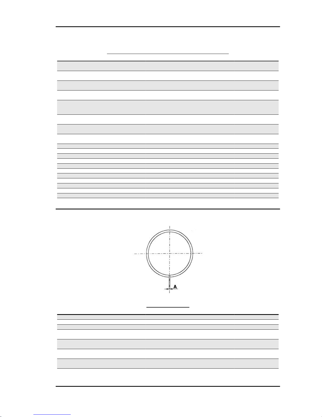
Removing the clutch
- Equip the tool with long pins screwed into position
«A» from the outside, insert the entire driven pulley
in the tool and have the central screw make contact.
CAUTION
THE TOOL WILL BE DEFORMED IF THE CENTRAL SCREW
IS TIGHTENED UP TOO FAR.
- Using a 34 mm socket wrench remove the clutch
locking nut.
- Loosen the central screw by undoing spring of
the driven pulley unit
- Separate the components.
Specific tooling
020444Y Tool for fitting/ removing the driven
pulley clutch
Liberty 50 4tempi Engine
ENG - 67
Page 68

Inspecting the clutch
- Check the thickness of the clutch mass friction
material.
- The masses must not show traces of lubricants;
otherwise, check the driven pulley unit seals.
N.B.
UPON RUNNING-IN, THE MASSES MUST EXHIBIT A CEN-
TRAL FAYING SURFACE AND MUST NOT BE DIFFERENT
FROM ONE ANOTHER.
VARIOUS CONDITIONS CAN CAUSE THE CLUTCH TO
TEAR.
CAUTION
DO NOT OPEN THE MASSES USING TOOLS TO PREVENT
A VARIATION IN THE RETURN SPRING LOAD.
Characteristic
Check minimum thickness
1 mm
Pin retaining collar
- Remove the collar with the aid of 2 screwdrivers.
- Remove the three guide pins and the mobile half
pulley.
Engine Liberty 50 4tempi
ENG - 68
Page 69

Removing the driven half-pulley bearing
- Remove the roller bearing with the special extractor inserted from the bottom of the fixed halfpulley.
CAUTION
POSITION THE HOLDING EDGE OF THE EXTRACTION PLI-
ERS BETWEEN THE END OF THE BEARING AND THE
BUILT IN SEAL RING.
Specific tooling
001467Y029 Bell for bearings, O.D. 38 mm
- Remove the ball bearing retention snap ring.
- Expel the ball bearing from the side of the clutch
housing by means of the special tool.
N.B.
PROPERLY SUPPORT THE HALF-PULLEY SO AS NOT TO
DEFORM THE SLIDING SURFACE OF THE DRIVE BELT
Specific tooling
020376Y Adaptor handle
020363Y 20-mm guide
Inspecting the driven fixed half-pulley
- Check that there are no signs of wear on the work
surface of the belt. If there are, replace the halfpulley..
- Make sure the bearings do not show signs of unusual wear.
- Measure the outside diameter of the pulley bushing.
Characteristic
Stationary driven half-pulley/Standard diameter
Ø 33.965 to 33.985 mm
Stationary driven half-pulley / Minimum diameter admitted after use
Ø 33.96 mm
Liberty 50 4tempi Engine
ENG - 69
Page 70

Inspecting the driven sliding half-pulley
- Remove the 2 inner sealing rings and the two Orings.
- Measure the inside diameter of the mobile halfpulley bushing.
Characteristic
Mobile driven half-pulley/ Maximum diameter
allowed
Ø 34.08 mm
- Check the belt contact surfaces.
- Insert the new oil seal and O-rings on the mobile
half-pulley.
- Fitting the half-pulley on the bushing.
Recommended products
AGIP GREASE SM 2 Gray black smooth-textured lithium grease, containing molybdenum
disulphide.
-
- Make sure the pins and collar are not worn, reassemble the pins and collar.
- Use a greaser with a curved spout to lubricate the driven pulley unit with around 6 g of grease. This
operation must be done through one of the holes inside the bushing until grease comes out of the
opposite hole. This procedure is necessary to prevent the presence of grease beyond the O-ring.
Recommended products
AGIP GREASE SM 2 Gray black smooth-textured lithium grease, containing molybdenum disulphide.
-
Refitting the driven half-pulley bearing
- Fit a new ball bearing with the specific tool.
- Fit the ball bearing retention snap ring.
- Fit the new roller bearing with the wording visible
from the outside.
CAUTION
PROPERLY SUPPORT THE HALF-PULLEY TO PREVENT
DAMAGE TO THE THREADED END WHILE THE BEARINGS
ARE BEING FITTED.
Specific tooling
020376Y Adaptor handle
Engine Liberty 50 4tempi
ENG - 70
Page 71

020456Y Ø 24 mm adaptor
020362Y 12 mm guide
020171Y Punch for Ø 17 mm roller bearing
Inspecting the clutch spring
- Check that the contrast spring of the driven pulley
does not show signs of deformation
- Measure the free length of the spring
Characteristic
Standard length
118 mm
Minimum length allowed after use
XXXX
- Check the thickness of the clutch mass friction
material.
-The masses must not show traces of lubricants;
otherwise, check the driven pulley unit.
N.B.
UPON RUNNING-IN, THE MASSES MUST EXHIBIT A CEN-
TRAL CONTACT SURFACE AND MUST NOT BE DIFFERENT FROM ONE ANOTHER. VARIOUS CONDITIONS CAN
CAUSE THE CLUTCH TO TEAR.
CAUTION
DO NOT OPEN THE MASSES USING TOOLS SO AS TO
PREVENT A VARIATION IN THE RETURN SPRING LOAD.
Characteristic
Minimum thickness permitted:
1 mm
Refitting the clutch
- Preassemble the driven pulley group with spring,
sheath and clutch.
- Position the spring with the sheath
- Insert the components in the tool and preload the
spring being careful not to damage the plastic
sheath and the end of the threaded shank.
Liberty 50 4tempi Engine
ENG - 71
Page 72

- Reassemble the nut securing the clutch and tighten to the prescribed torque.
CAUTION
SO AS NOT TO DAMAGE THE CLUTCH NUT USE A SOCK-
ET WRENCH WITH SMALL CHAMFER.
CAUTION
POSITION THE NON-CHAMFERED SURFACES OF THE
NUT IN CONTACT WITH THE CLUTCH
Locking torques (N*m)
Nut locking clutch unit on pulley 55 to 60 Nm
Refitting the driven pulley
-Refit the driven pulley assembly, the clutch bell
and the nut, using the specific tool.
Specific tooling
020565Y Flywheel lock calliper spanner
Locking torques (N*m)
Driven pulley shaft nut 40 to 44 Nm
Drive-belt
- Make sure the drive belt is not damaged and does
not have cracks in the toothed grooves.
- Check the width of the belt.
Characteristic
Transmission belt/Minimum width
17.5 mm
Engine Liberty 50 4tempi
ENG - 72
Page 73

Removing the driving pulley
- Lock the driving pulley using the appropriate tool.
- Remove the central nut with the related washer,
then remove the drive and the plastic fan.
- Remove the stationary half-pulley.
- Remove the belt, washer and remove the mobile half-pulley with its bushing, being careful that the
rollers and contrast plate fitted loosely on it do not come off.
Specific tooling
020451Y Starting ring gear lock
Inspecting the rollers case
1) Check that the bushing and the sliding rings of
the mobile pulley do not show signs of scoring or
deformation.
2) Check the roller running tracks on the contact
pulley; there must not be signs of wear and check
the condition of the contact surface of the belt on
the half-pulleys (mobile and stationary).
3) Check that the rollers do not show signs of
marked facetting on the sliding surface and that
the metallic insert does not come out of the plastic
shell borders.
4) Check the integrity of the sliding shoes of the
contact plate.
- Check that the internal bushing shown in the figure is not abnormally worn and measure inside
diameter «A».
- Measure outside diameter «B» of the pulley sliding bushing shown in the figure.
CAUTION
DO NOT LUBRICATE OR CLEAN THE BUSHING.
Characteristic
Driving pulley / Maximum diameter:
Liberty 50 4tempi Engine
ENG - 73
Page 74

20.12 mm
Driving pulley/ Standard diameter:
20.021 mm
Driving pulley bushing/ Diameter maximum:
XXX mm
Driving pulley bushing/ Standard diameter:
20 -0.020/-0.041mm
Refitting the driving pulley
- Manually move the movable driven half-pulley
away by pulling it towards the clutch unit and insert
the belt observing the direction of rotation of the
first fitting.
N.B.
IT IS GOOD PRACTICE ALWAYS TO FIT THE BELT SO
THAT THE WORDS CAN BE READ IN CASE IT DOES NOT
SHOW A FITTING SIDE.
- Refit the components of the assembly (roller
housing assembly with bushing, limiting washer,
stationary half-pulley, cooling fan belt with drive,
washer and nut).
- With the specific tool, tighten the lock nut to 20
Nm and then perform a final 90° locking in order to
prevent the rotation of the driving pulley.
N.B.
REPLACE THE NUT WITH A NEW ONE AT EVERY REFIT
CAUTION
UPON FITTING THE DRIVING PULLEY UNIT IT IS OF UT-
MOST IMPORTANCE THAT THE BELT IS FREE INSIDE IN
ORDER TO AVOID WRONG TIGHTENING AND CONSEQUENTLY DAMAGING THE CRANKSHAFT KNURLING.
Specific tooling
020451Y Starting ring gear lock
Locking torques (N*m)
Crankshaft pulley nut 18 to 20 + 90° Nm
Engine Liberty 50 4tempi
ENG - 74
Page 75

Refitting the transmission cover
- Check the following for wear: toothed section,
toothed section shaft, cover seat bushing, pinion
shaft and its seating in the crankcase and the return spring.
- Remove the damaged components.
- Grease the spring.
- Remove the toothed sector and load the spring
with an appropriate tool.
- Refit the washer, the Seeger and the Kick-start
lever.
Recommended products
AGIP GREASE MU3 Yellow-brown, lithiumbase, medium-fibre multipurpose grease.
ISO L-X-BCHA 3 - DIN 51 825 K3K -20
- Insert the pinion in its seating by pushing the starter lever.
- Fit the intake throat and tighten the 3 screws.
-Make sure the oil sump presents centring dowels
and sealing gaskets.
- Replace the cover tightening the 12 screws to the
prescribed torque.
-Refit the oil filling cap.
Locking torques (N*m)
Transmission cover screws 11 to 13 Nm
End gear
Liberty 50 4tempi Engine
ENG - 75
Page 76

Removing the hub cover
- Drain the rear hub oil
- Remove driven pulley
- Remove the rear brake shoes
- Remove the 5 screws fixing the cover to the
crankcase
- Remove the cover with the wheel axle and pull it
out
- Remove the intermediate gear with the appropriate shim washers
Removing the wheel axle bearings
- Remove the oil seal and the seeger ring.
- Fix the hub cover properly to avoid damaging the
sealing surface with the housing
- Remove the wheel axle bearing using the specific
tool
Specific tooling
020363Y 20-mm guide
020376Y Adaptor handle
020477Y 37 mm adaptor
Engine Liberty 50 4tempi
ENG - 76
Page 77

Removing the driven pulley shaft bearing
- Remove the seeger ring
- Heat the engine crankcase but do not direct the
hot air towards the bearing
- Extract the driven pulley shaft together with the
bearing with a few mallet blows
- Remove the bearing off the driven pulley shaft
using the specific tool and a press
N.B.
USE THE SPECIFIC TOOL ON THE SIDE WITH THE SMALL-
ER INTERNAL DIAMETER
Specific tooling
020452Y Tube for removing and refitting the
driven pulley shaft
Liberty 50 4tempi Engine
ENG - 77
Page 78

Inspecting the hub shaft
- Check the three shafts for wear or distortion of
the toothed surfaces, the bearing housings, and
the oil seal housings.
- If faults are found, replace the damaged components.
- Check capacity (A) of the transmission gear
(wear, deformations, etc.)
- Check the pulley shaft seating: Superficial wear
(B) may indicate irregularities in the crankcase
seats or in the pulley shaft capacities
Inspecting the hub cover
- Check that the fitting surface is not dented or distorted.
- If faults are found, replace the hub cover.
Refitting the wheel axle bearing
- Support the hub cover on a wooden surface
- Heat up the hub cover using the thermal gun.
- Preassemble the bearing on the specific punch
using grease and then insert the bearing in its
seating
- Refit the seeger ring and the oil seal using the 42
x 47 mm adaptor
N.B.
POSITION THE OIL SEAL WITH THE SEALING LIP FACING
THE HUB INTERNAL SIDE
Specific tooling
020150Y Air heater mounting
020151Y Air heater
020376Y Adaptor handle
Engine Liberty 50 4tempi
ENG - 78
Page 79

020363Y 20-mm guide
020359Y 42x47-mm Adaptor
Refitting the hub bearings
- Remove the wheel axle on the cover and pay attention not to damage the sealing lip of the oil seal
- Apply a thin layer of grease on the two shim
washers of the intermediate gear and fit one on the
cap so that it does not interfere with the wheel axle
gear when placing the transmission shaft
Refitting the ub cover
- Apply product recommended for surfaces on the
hub cap and refit cap on the crankcase
- Fit the 5 screws and tighten them to the specified
torque.
N.B.
CLEAN THE CONTACT SURFACES OF THE HUB COVER
AND THE HALF CRANKCASE OF RESIDUE FROM PREVIOUS GASKETS BEFORE APPLYING A NEW ONE.
Recommended products
Loctite 510 Liquid sealant
Liberty 50 4tempi Engine
ENG - 79
Page 80

Gasket
Locking torques (N*m)
hub cap screws 24 - 26
Flywheel cover
Cooling hood
- Remove the manifold and the carburettor undoing the 2 fixing screws on the head
- Remove the fastening clamp of the secondary air
pipe and disconnect it
- Remove the 4 front coupling screws (1 of them is
a knob) and the side fixing screw at the crankcase
base.
- Remove the 4 side screws
- Extract the 3 covers - Remove the cover sealing
gaskets on the head
- For refitting, repeat the removal steps but in reverse order
CAUTION
TAKE CARE TO CORRECTLY POSITION THE FLYWHEEL
CONNECTOR.
N.B.
WHEN REFITTING THE COVER, TAKE CARE NOT TO DAM-
AGE THE STATOR WIRING.
Engine Liberty 50 4tempi
ENG - 80
Page 81

Cooling fan
- Remove the cooling fan by undoing the 3 screws
fixing it to the rotor
- When refitting the fan, pay attention that the
screw holes in the fan and the rotor coincide, then
tighten screws at the specified torque.
Removing the stator
- Remove the 2 Pick-Up screws and the 2 stator
fixing screws indicated in the figure.
- Remove the stator and its wiring.
Refitting the stator
- Refit the stator and flywheel carrying out the removal procedure in reverse, tightening the retainers to the specified torque.
N.B.
THE PICK-UP CABLE MUST BE POSITIONED ADHERING
TO THE FUSION TONGUE ON THE CRANKSHAFT IN SUCH
A WAY AS TO AVOID BEING CRUSHED BY THE FAN COVER ASSEMBLY.
Locking torques (N*m)
Pick-up screws 3 ÷ 4 Stator screws 3 to 4
Flywheel and starting
Liberty 50 4tempi Engine
ENG - 81
Page 82

Removing the starter motor
- Undo the screw on the power positive contact
and disconnect the cable
- Undo the 2 screws fixing the starter motor to the
crankcase and recover the power wiring.
Removing the flywheel magneto
- Lock the rotation of the flywheel using the calliper
spanner.
- Remove the nut.
CAUTION
THE USE OF A CALLIPER SPANNER OTHER THAN THE
ONE SUPPLIED COULD DAMAGE THE STATOR COILS
- Extract the flywheel with the extractor.
Specific tooling
020565Y Flywheel lock calliper spanner
020162Y Flywheel extractor
Engine Liberty 50 4tempi
ENG - 82
Page 83

Inspecting the flywheel components
- Check that the flywheel internal magnets are in
good conditions.
- Check that the flywheel splines exhibit no loosening.
- Check there are no deformations that may cause
rubbing on the stator and the Pick-Up.
- Check that the stator winding, its ferromagnetic
support and the pick-up are in good conditions.
Starter gear rim
- Check the toothing is level and in good conditions
Intermediate gear
- Check that the keying toothing on the crown and
the starter motor are in good conditions.
- Check that the Bendix opens and returns adequately.
Liberty 50 4tempi Engine
ENG - 83
Page 84

Refitting the flywheel magneto
- Refit the stator and the pick-up being careful to
pass the wiring through the appropriate crankcase
couplings.
- Refit the flywheel to the crankshaft being careful
to respect the keying, then lock rotation with the
specific tool and tighten the nut to the prescribed
torque.
N.B.
A VARIATION OF THE AIR GAP DISTANCE CAN LEAD TO
A VARIATION IN THE IGNITION ADVANCE SUCH AS TO
CAUSE PINGING, KNOCKING ETC.
Specific tooling
020565Y Flywheel lock calliper spanner
Locking torques (N*m)
Flywheel nut 52 to 58
Refitting the starter motor
- Install the starter motor in its seating in the crankcase.
- Tighten the screw on the head side but do not
lock it, screw the second screw inserting the earth
cable (black), then tighten the 2 screws at the prescribed torque.
- Tighten the locking screw of the positive cable
(red) on the side contact.
N.B.
REFIT THE REMAINING PARTS AS DESCRIBED IN THE
CYLINDER HEAD, TIMING, LUBRICATION, FLYWHEEL
AND TRANSMISSION CHAPTERS.
Locking torques (N*m)
Starter screws 11 to 13
Cylinder assy. and timing system
Engine Liberty 50 4tempi
ENG - 84
Page 85

Removing the rocker-arms cover
- Remove the cooling covers
- Remove the 4 retainers of the tappet cover
- Remove the cover and the O-ring
- Remove the 4 screws and then remove the Blowby cover
- Clean the nozzle labyrinth and the membrane
(replace it, if necessary), then remove the cover
unit.
See also
Cooling hood
Removing the timing system drive
- Temporarily loosen the tensioner central screw
and remove it together with the spring.
- Unscrew the 2 retainers indicated in the figure
and remove the chain tightener support being
careful to recover the sealing gasket.
N.B.
SHOULD THE GASKET NOT BE IN GOOD CONDITIONS,
REPLACE IT AFTER CAREFULLY CLEANING THE FAYING
SURFACE IN ORDER TO AVOID ENGINE OIL LEAKS
Liberty 50 4tempi Engine
ENG - 85
Page 86

- Remove the driving pulley
- Remove the oil pump chain
- Remove the tappet cover
- Remove the central screw and the belleville
washer indicated in the figure and lock the camshaft crown with the specific tool.
N.B.
TO FACILITATE REMOVING THE HEAD COMPONENTS,
SET THE CRANKSHAFT TO THE TIMING POINT (TDC OF
THE COMPRESSION END).
Specific tooling
020565Y Flywheel lock calliper spanner
- Remove the camshaft control pulley and the washer below.
- Remove the pinion of the crankshaft timing control
- To remove the chain lower guiding pad, remove the head by pulling it upwards
N.B.
IT IS ADVISABLE TO MARK THE CHAIN IN ORDER TO ENSURE THAT THE DIRECTION OF ROTATION IS MAINTAINED.
See also
Removing the driving pulley
Removing the rocker-arms cover
Removal
Removing the cam shaft
- Remove the bearing clamping screw indicated in
the figure.
- Remove the entire camshaft with bearing using
the specific tool shown in the figure.
- Take out the camshaft bearing with the aid of the
specific tool, being careful to mount a screw on the
camshaft in order to protect its thread.
N.B.
IF A BEARING SEPARATES FROM THE CAMSHAFT, IT IS
ESSENTIAL TO FIT A NEW BEAR.
Specific tooling
Engine Liberty 50 4tempi
ENG - 86
Page 87

020450Y Camshaft fitting/removal tool
004499Y Camshaft bearing extractor
004499Y001 Bearing extractor bell
004499Y002 Bearing extractor screw
004499Y006 Bearing extractor ring
004499Y027 Bearing extractor part
- Pull out the rocking lever bolt operating on the
flywheel hole and remove the rocking levers at the
same time.
N.B.
MARK THE ASSEMBLY POSITION OF THE ROCKING LEV-
ERS IN ORDER TO AVOID MISPLACING THE INTAKE AND
DISCHARGE ENDS.
Removing the cylinder head
- Remove the cooling covers, the timing control,
the camshaft and the rocking levers.
- Remove the spark plug.
- Remove the 2 side fixings shown in the figure.
- Loosen the 4 head-cylinder fastening nuts in two
or three stages and in criss-cross fashion.
- Remove the head, the two alignment dowels and
the gasket.
N.B.
IF NEEDED, THE HEAD MAY BE REMOVED WITH THE
CAMSHAFT, PINS AND ROCKING LEVERS WITHOUT REMOVING THE DRIVING PULLEY UNIT. REMEMBER TO
HOLD THE TIMING CHAIN WITH A PIECE OF METAL CABLE AND TO ADJUST THE CHAIN TIGHTENER UPON REFITTING.
Liberty 50 4tempi Engine
ENG - 87
Page 88

Removing the valves
- Using the specific tool fitted with the element
shown in the figure, remove the cotters, the caps
and the spring between the valves.
- Remove the oil seals with the appropriate tool.
- Remove the lower spring supports.
Specific tooling
020431Y Valve oil seal extractor
Removing the cylinder - piston assy.
- Remove the cylinder paying attention to the 2
cylinder centring dowels in the housing.
- Remove the cylinder base gasket.
To avoid damaging the piston, keep it fixed while
removing the cylinder.
- Remove the two stop rings, the wrist pin and the
piston.
- Remove the 3 piston rings from the piston.
N.B.
BE CAREFUL NOT TO DAMAGE THE PISTON RINGS DUR-
ING REMOVAL.
Engine Liberty 50 4tempi
ENG - 88
Page 89

Inspecting the small end
- Measure the internal diameter of the connecting
rod small end using an internal micrometer.
N.B.
IF THE DIAMETER OF THE CONNECTING ROD SMALL
END EXCEEDS THE MAXIMUM DIAMETER ALLOWED,
SHOWS SIGNS OF WEAR OR OVERHEATING REPLACE
THE CRANKSHAFT AS DESCRIBED IN THE "CRANKCASE
AND CRANKSHAFT" CHAPTER".
Characteristic
Max. diameter admitted: check the small end
13.030 mm
Standard diameter: check the small end
13 +0.025+0.015mm
Inspecting the wrist pin
- Measure the outer diameter of the gudgeon pin.
Characteristic
Standard diameter: gudgeon pin
13 -0 -0.004mm
Minimum admissible diameter gudgeon pin
12.990 mm
Inspecting the piston
- Calculate the piston pin coupling clearance.
Fitting clearance
Pin coupling clearance 13 +0.010+0.005mm 0.005 to
0.014 mm
- Measure the outside diameter of the piston, perpendicular to the gudgeon pin axis.
- Carry out the measurement at 27 from the piston crown as shown in the figure.
- Carefully clean the sealing rings housings with the aid of an old piston ring.
Liberty 50 4tempi Engine
ENG - 89
Page 90

- Measure the coupling clearance between the sealing rings and the piston grooves using a thickness
gauge, as shown in the figure.
- If the clearances detected exceed the limits specified in the table, the piston and the piston rings should
be replaced.
PISTON
Name Description Dimensions Initials Quantity
Top piston ring 0.030 ÷ 0.065 mm 0.080 mm
Middle piston ring 0.020 ÷ 0.055 mm 0.070 mm
oil scraper 0.040 ÷ 0.160 mm 0.20 mm
Inspecting the cylinder
- Using a bore meter, measure the inner cylinder
diameter at three different points according to the
directions shown in the figure.
- Check that the coupling surface with the head is
not worn or misshapen.
- Pistons and cylinders are classified into categories based on their diameter. The coupling is carried out in pairs (A-A, B-B, C-C, D-D).
Characteristic
Maximum allowable run-out:
0.001 in 0.05 mm
- The cylinder rectifying operation should be carried out with a surfacing that respects the original
angle. at 120° crossed.
- The cylinder surface roughness should be of
R.A.= 0.30 ÷ 0.50.
- This is indispensable for a good seating of the
sealing rings, which in turn minimises oil consumption and guarantees optimum performance.
Engine Liberty 50 4tempi
ENG - 90
Page 91

- The pistons are oversized due to cylinder rectification and are subdivided into two categories 1st
and 2nd with 0.2-0.4mm oversize. They are also
classified into 4 categories A-A, B-B, C-C, D-D.
Inspecting the piston rings
- Alternately insert the three sealing rings into the cylinder, in the area where it retains its original diameter. Using the piston, insert the rings perpendicularly to the cylinder axis.
- Measure the opening, see figure, of the sealing rings using a thickness gauge.
- If any measurements are greater than specified, replace the piston rings.
N.B.
BEFORE REPLACING ONLY THE PISTON RINGS, ENSURE THAT THE CLEARANCE BETWEEN
THE PISTON RINGS AND THE PISTON RING GROOVES, AND BETWEEN THE PISTON AND THE
CYLINDER, IS AS SPECIFIED. IN ANY CASE, NEW PISTON RINGS USED IN COMBINATION WITH
A USED CYLINDER MAY HAVE DIFFERENT BEDDING CONDITIONS THAN THE STANDARD.
SEALING RINGS
Name
Description Dimensions Initials Quantity
Top piston ring 0.08 ÷ 0.20 mm 0.35 mm
Middle piston ring 0.05 ÷ 0.20 mm 0.30 mm
oil scraper 0.20 ÷ 0.70 mm 0.80 mm
Liberty 50 4tempi Engine
ENG - 91
Page 92

Removing the piston
- Install piston and wrist pin onto the connecting
rod, aligning the piston arrow the arrow facing towards the exhaust.
- Fit the pin retainer ring onto the appropriate tool.
Specific tooling
020448Y Pin lock fitting tool
- With the opening in the position indicated on the
tool, set the lock ring into position in the tool with
the punch.
- Rest the tool on the piston paying attention that
the 90°chamfered side faces upwards as indicated
in the figure.
- Fit the gudgeon pin stop using the plug.
CAUTION
USING A HAMMER TO POSITION THE RINGS CAN DAM-
AGE THE LOCKING HOUSING.
Choosing the gasket
This engine is manufactured with two different head gasket solutions:
- Fibre gasket drw. 969244 0.95 mm thick.
- Steel gasket drw. 969393 0.3 mm thick.
In order to guarantee an adequate compression ratio, the gaskets match cylinders with different heights:
- Fibre gaskets with cylinder 56.45 mm high
- Fibre gaskets with cylinder 57.15 mm high
In order to carry out the revision both gaskets should be present on the spare parts.
All pin-piston-cylinder units supplied with the spare parts present cylinders 57.15 mm high
- Provisionally fit the piston into the cylinder, without any base gasket.
- Fit a dial gauge on the specific tool, then rest both on a stop surface.
- Zero set the dial gauge on the stop surface. Keeping the zero position, assemble the tool on the cylinder
and lock it with 2 nuts as shown in the figure.
- Rotate the crankshaft up to the TDC (the inversion point of the dial gauge rotation)
- Measure piston protrusion compared with the head plane and determine the gasket thickness to be
used according to the table below. By correctly identifying the cylinder base gasket thickness, an adequate compression ratio is maintained.
- Remove the special tool and the cylinder.
Engine Liberty 50 4tempi
ENG - 92
Page 93

Characteristic
Standard compression ratio
C.R. 11.5 ÷ 12 ÷ 1
CYLINDER BASE GASKET THICKNESS
Specification Desc./Quantity
Cylinder height 56.45 ± 0.05
Head gasket thickness (fibre) 0.95 ± 0.06
Value measured 0.9 ± 0.05
Base gasket thickness 0.4
Value measured 1 ± 0.05
Base gasket thickness 0.5
CYLINDER BASE GASKET THICKNESS
Specification Desc./Quantity
Cylinder height 57.15 ± 0.05
Head gasket thickness (steel) 0.3 ± 0.05
Value measured 0.20 ± 0.05
Base gasket thickness 0.4
Value measured 0.30 ± 0.05
Base gasket thickness 0.5
N.B.
MEASUREMENT "A" TO BE TAKEN IS A VALUE OF PISTON RE-ENTRY, IT INDICATES BY HOW
MUCH THE PLANE FORMED BY THE PISTON CROWN FALLS BELOW THE PLANE FORMED BY
THE TOP OF THE CYLINDER. THE FURTHER THE PISTON GETS INSIDE THE CYLINDER, THE
THINNER THE HEAD GASKET TO BE APPLIED SHOULD BE (TO RECOVER THE COMPRESSION
RATIO) AND VICE VERSA.
Characteristic
Shimming system for keeping the compression ratio
CR: 11.1 to 12.9
PISTON PROTRUSION CHECK
Name
Measure A Thickness
shimming_1 0.05 to 0.25 0.35
shimming_2 0.25 to 0.40 0.25
Liberty 50 4tempi Engine
ENG - 93
Page 94

Engine Liberty 50 4tempi
ENG - 94
Page 95

Refitting the piston rings
- Fit the oil scraper ring starting from the spring,
taking care that the spring ends do not superimpose. Fit the two piston rings so that their gaps and
that of the oil scraper ring are never aligned.
- Fit the 2nd sealing ring with the identifying letter
«T» facing towards the piston crown.
- Fit the 1st sealing ring with the reference letter
«T» facing towards the piston crown.
- Misalign the lining openings at 120° as shown in
the figure.
- Lubricate the components with engine oil.
N.B.
IN ORDER TO OBTAIN A GOOD BEDDING, THE 2 SEALING
PISTON RINGS ARE MADE OF CONE SHAPED CONTACT
SECTION TO THE CYLINDER. AS A RESULT IT IS IMPORTANT TO RESPECT THE FITTING INSTRUCTION TO ASSEMBLY THE RINGS WITH THE "T" MARK FACING
UPWARDS.
- Alternately insert the three sealing rings into the
cylinder, in the area where it retains its original diameter. Using the piston, insert the rings perpendicularly to the cylinder axis.
- Measure the opening, see figure, of the sealing
rings using a thickness gauge.
- If any measurements are greater than specified,
replace the piston rings.
N.B.
BEFORE REPLACING ONLY THE PISTON
RINGS, ENSURE THAT THE CLEARANCE BETWEEN THE PISTON RINGS AND THE PISTON
RING GROOVES, AND BETWEEN THE PISTON
AND THE CYLINDER, IS AS SPECIFIED. IN ANY
CASE, NEW PISTON RINGS USED IN COMBI-
Liberty 50 4tempi Engine
ENG - 95
Page 96

NATION WITH A USED CYLINDER MAY HAVE
DIFFERENT BEDDING CONDITIONS THAN
THE STANDARD.
SEALING RINGS
Name DescriptionDimensionsInitials Quantity
Top piston
ring
0.08 ÷
0.20 mm
0.35 mm
Middle pis-
ton ring
0.05 ÷
0.20 mm
0.30 mm
oil scraper 0.20 ÷
0.70 mm
0.80 mm
Refitting the cylinder
- Insert the cylinder base gasket with the thickness
determined above.
- Fit the cylinder as shown in the figure.
- The piston can be kept out of the housing plane
using the appropriate tool.
N.B.
BEFORE FITTING THE CYLINDER, CAREFULLY BLOW
OUT THE LUBRICATION DUCT AND OIL THE CYLINDER
BARREL.
Specific tooling
020288Y Fork to assemble piston on cylinder
If the four cylinder stud bolts should be replaced in this kind of engine, it is necessary to tighten the
head nuts strictly following the procedure below.
The procedure is different from that indicated in the vehicle manuals:
Head nuts tightening (only for stud bolts replacement) 6÷7 N*m +90° + 90° + 90°
The 45° rotation reduction of the key is necessary to avoid stud bolt stretching.
Inspecting the cylinder head
- Using a trued bar check that the cylinder head
surface is not worn or distorted.
- Check that the camshaft and rocking lever pin
bearings show no signs of wear.
- Check that the cylinder head cover surface, the
intake manifold and the exhaust manifold are not
worn.
Characteristic
Maximum admitted unevenness: Cylinder
head check
Engine Liberty 50 4tempi
ENG - 96
Page 97

0.05 mm
HEAD CHECK
Specification Desc./Quantity
Standard diameter (mm) A Ø 32.015 to 32.025
Standard diameter (mm) B Ø 16.0 to 16.018
Standard diameter (mm) C Ø 11.0 to 11.018
Inspecting the timing system components
- Check that the guide slider and the tensioner
slider are not worn out.
- Ensure that the camshaft drive pulley, the chain
assembly and the sprocket wheel are not worn.
- If sings of wear are found, replace the parts. if the
chain, pinion or pulley are worn, replace the whole
assembly.
- Remove the central screw and the tensioner
spring. Check that the one-way mechanism is not
worn.
- Check the condition of the tensioner spring.
- If examples of wear are found, replace the whole
unit.
Liberty 50 4tempi Engine
ENG - 97
Page 98

Inspecting the valve sealings
- Insert the valves into the cylinder head.
- Test the 2 valves alternatively.
- The test is carried out by filling the manifold with
petrol and checking that the head does not ooze
through the valves when these are just pressed
with the fingers.
- Measure the width of the sealing surface on the
valve seats.
Characteristic
Sealing surface width: Intake
1.5 mm
Sealing surface width: Drainage
1.6 mm
Inspecting the valve housings
- Remove any carbon formation from the valve
guides.
- Measure the inside diameter of each valve guide.
- Take the measurement at three different heights
in the rocker arm push direction.
Characteristic
Discharge guide: Standard diameter
5 +0+0.012mm
Discharge guide: Wear limit
5.022 mm
Intake guide: Standard diameter
5 +0+0.012mm
Intake guide: Wear limit
5.022 mm
- If the width of the impression on the valve seat or the diameter of the valve guide exceed the specified
limits, replace the cylinder head.
- Check width of the impression on the valve seat «V»
Characteristic
Engine Liberty 50 4tempi
ENG - 98
Page 99

Wear limits:
Max. 1.6 mm
Inspecting the valves
- Measure the diameter of the valve stems in the
three positions indicated in the diagram.
- Calculate the clearance between valve and valve
guide.
Characteristic
Minimum diameter allowed: Intake
4.970 mm
Minimum admissible diameter drainage
4.960 mm
Fitting clearance
Standard clearance: Intake 0.015 to 0.042 mm
Standard clearance: drainage 0.025 to 0.052 mm
- Check that there are no signs of wear on the
contact surface with the articulated register terminal.
- If the sealing surface on the valves is wider than
the specified limit, damaged in one or more points
or curved, replace the valve with a new one.
Characteristic
Valve standard length: Intake
70.1 mm
Valve standard length: Exhaust
69.2 mm
Fitting clearance
Max. clearance allowed: Intake 0.052 mm Max.
clearance allowed: drainage 0.062 mm
- If no faults are found during the above checks, you can use the same valves. For best sealing results,
it is advisable to grind the valves. Grind the valves gently with a fine-grained lapping compound. During
grinding, keep the cylinder head in a horizontal position. This will prevent the lapping compound residues from penetrating between the valve stem/guide coupling.
CAUTION
TO AVOID SCORING THE FAYING SURFACE, DO NOT KEEP ROTATING THE VALVE WHEN NO
LAPPING COMPOUND IS LEFT. CAREFULLY WASH THE CYLINDER HEAD AND THE VALVES
WITH A SUITABLE PRODUCT FOR THE TYPE OF LAPPING COMPOUND BEING USED.
Liberty 50 4tempi Engine
ENG - 99
Page 100

Inspecting the springs and half-cones
- Check that the upper spring caps and the cotter
halves show no signs of abnormal wear.
Refitting the valves
- Lubricate the valve guides with graphite grease.
- Place the lower caps of the valve spring on the
head.
- Use the punch to fit the 2 sealing rings one at a
time.
Specific tooling
020306Y Punch for assembling valve seal
rings
- Fit the valves, the springs and the upper caps.
- Using the appropriate tool, compress the springs
and insert the cotters in their seats.
Inspecting the cam shaft
- Inspect the camshaft for signs of abnormal wear
on the cams.
Characteristic
Standard diameter - Bearing A:
Ø 12 +0.002 +0.010
mm Standard diameter - Bearing B:
Ø 16-0.015 -0.023 mm
Minimum diameter allowed - Bearing A:
Engine Liberty 50 4tempi
ENG - 100
 Loading...