

Page 1

Operation and
Maintenance
Manual
SEBU8190-00
April 2006
4006 TRS Gas and 4008 TRS Gas
Industrial Engines
Page 2

Important Safety Information
Most accidents that involve product operation, maintenance and repair are caused by failure to
observe basic safety rules or precautions. An accident can often be avoided by recognizing potentially
hazardous situations before an accident occurs. A person must be alert to potential hazards. This
person should also have the necessary training, skills and tools to perform these functions properly.
Improper operation, lubrication, maintenance or repair of this product can be dangerous and
could result in injury or death.
Do not operate or perform any lubrication, maintenance or repair on this product, until you have
read and understood the operation, lubrication, maintenance and repair information.
Safety precautions and warnings are provided in this manual and on the product. If these hazard
warnings are not heeded, bodily injury or death could occur to you or to other persons.
The hazards are identified by the “Safety Alert Symbol” and followed by a “Signal Word” such as
“DANGER”, “WARNING” or “CAUTION”. The Safety Alert “WARNING” label is shown below.
The meaning of this safety alert symbol is as follows:
Attention! Become Alert! Your Safety is Involved.
The message that appears under the warning explains the hazard and can be either written or
pictorially presented.
Operations that may cause product damage are identified by “NOTICE” labels on the product and in
this publication.
Perkins cannot anticipate every possible circumstance that might involve a potential hazard. The
warnings in this publication and on the product are, therefore, not all inclusive. If a tool, procedure,
work method or operating technique that is not specifically recommended by Perkins is used,
you must satisfy yourself that it is safe for you and for others. You should also ensure that the
product will not be damaged or be made unsafe by the operation, lubrication, maintenance or
repair procedures that you choose.
The information, specifications, and illustrations in this publication are on the basis of information that
was available at the time that the publication was written. The specifications, torques, pressures,
measurements, adjustments, illustrations, and other items can change at any time. These changes can
affect the service that is given to the product. Obtain the complete and most current information before
you start any job. Perkins dealers or Perkins distributors have the most current information available.
When replacement parts are required for this
product Perkins recommends using Perkins
replacement parts.
Failure to heed this warning can lead to premature failures, product damage, personal injury or
death.
Page 3

SEBU8190 3
Table of Contents
Table of Contents
Foreword ............................................. .................... 4
Safety Section
Safety Messages .................................................... 5
General Hazard Information ................................... 7
Burn Prevention ...................................................... 9
Fire Prevention and Explosion Prevention .............. 9
Crushing Prevention and Cutting Prevention ......... 11
Mounting and Dismounting .................................... 11
Ignition Systems .................................................... 11
Before Starting Engine ........................................... 11
Engine Starting ..................................................... 12
Engine Stopping ................................................... 12
Index Section
Index ..................................................................... 68
Electrical System .................................................. 12
Product Information Section
Model Views and Specifications ........................... 14
Product Identification Information ........................ 20
Operation Section
Lifting and Storage ................................................ 22
Gauges and Indicators .......................................... 23
Features and Controls .......................................... 24
Engine Starting ..................................................... 27
Engine Operation .................................................. 30
Engine Stopping ................................................... 31
Maintenance Section
Refill Capacities .................................................... 33
Maintenance Interval Schedule ............................ 36
Reference Information Section
Reference Materials .............................................. 64
Page 4

4 SEBU8190
Foreword
Foreword
Literature Information
This manual con
lubrication and maintenance information. This
manual should be stored in or near the engine area
in a literatur
study and keep it with the literature and engine
information.
English is the primary language for all Perkins
publications. The English used facilitates translation
and consiste
Some photographs or illustrations in this manual
show details
from your engine. Guards and covers may have
been removed for illustrative purposes. Continuing
improvemen
may have caused changes to your engine which are
not included in this manual. Whenever a question
arises reg
consult with your Perkins dealer or your Perkins
distributor for the latest available information.
Safety
This safety section lists basic safety precautions.
In addition, this section identifies hazardous,
warning si
precautions listed in the safety section before
operating or performing lubrication, maintenance and
repair on
this product.
tains safety, operation instructions,
e holder or literature storage area. Read,
ncy.
or attachments that may be different
t and advancement of product design
arding your engine, or this manual, please
tuations. Read and understand the basic
Recommended se
appropriate intervals as indicated in the Maintenance
Interval Schedule. The actual operating environment
of the engine a
Schedule. Therefore, under extremely severe,
dusty, wet or freezing cold operating conditions,
more frequen
specified in the Maintenance Interval Schedule may
be necessary.
The maintenance schedule items are organized for
a preventive maintenance management program. If
the prevent
periodic tune-up is not required. The implementation
of a preventive maintenance management program
should mini
avoidances resulting from reductions in unscheduled
downtime and failures.
ive maintenance program is followed, a
mize operating costs through cost
rvice should be performed at the
lso governs the Maintenance Interval
t lubrication and maintenance than is
Maintenance Intervals
Perform maintenance on items at multiples of
the original requirement. We recommend that the
maintenan
near the engine as a convenient reminder. We also
recommend that a maintenance record be maintained
as part of
Your authorized Perkins dealer or your Perkins
distribu
maintenance schedule to meet the needs of your
operating environment.
ce schedules be reproduced and displayed
the engine’s permanent record.
tor can assist you in adjusting your
Overhaul
Operatio
Operating techniques outlined in this manual are
basic. Th
techniques required to operate the engine more
efficiently and economically. Skill and techniques
develop
engine and its capabilities.
The oper
Photographs and illustrations guide the operator
through procedures of inspecting, starting, operating
and sto
discussion of electronic diagnostic information.
n
ey assist with developing the skills and
as the operator gains knowledge of the
ation section is a reference for operators.
pping the engine. This section also includes a
Maintenance
The mai
The illustrated, step-by-step instructions are grouped
by service hours and/or calendar time maintenance
interv
referenced to detailed instructions that follow.
ntenance section is a guide to engine care.
als. Items in the maintenance schedule are
Major engine overhaul details are not covered in
the Operation and Maintenance Manual except
for the i
interval. Major repairs should only be carried out by
Perkins authorized personnel. Your Perkins dealer
or your P
regarding overhaul programs. If you experience
a major engine failure, there are also numerous
after f
your Perkins dealer or your Perkins distributor for
information regarding these options.
nterval and the maintenance items in that
erkins distributor offers a variety of options
ailure overhaul options available. Consult with
California Proposition 65 Warning
Diesel engine exhaust and some of its c onstituents
are known to the State of California to cause cancer,
defects, and other reproductive harm. Battery
birth
posts, terminals and related accessories contain lead
and lead compounds. Wash hands after handling.
Page 5
SEBU8190 5
Safety Section
Safety Messages
Safety Section
i02409464
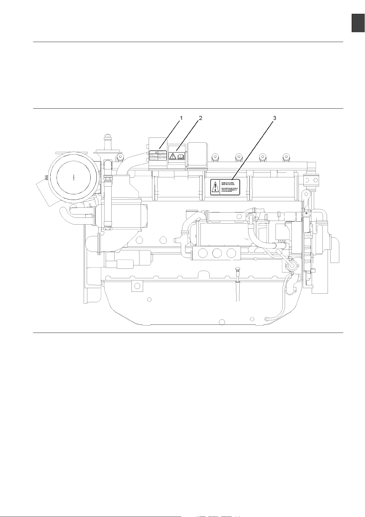
Safety Messages
Illustration 1
Typical example
(1) E ngine Derate (2) Universal warning (3) Engine Oil Level
There may be several specific warning signs on your
engine. The exact location and a description of the
warning signs are reviewed in this section. Please
become familiar with all warning signs.
Ensure that all of the warning signs are legible. Clean
the warning signs or replace the warning signs if
the words cannot be read or if the illustrations are
not visible. Use a cloth, water, and soap to clean
the warning signs. Do not use solvents, gasoline, or
other harsh chemicals. Solvents, gasoline, or harsh
chemicals could loosen the adhesive that secures the
warning signs. The warning signs that are loosened
could drop off of the engine.
Replace any warning sign that is damaged or
missing. If a warning sign is attached to a part of the
engine that is replaced, install a new warning sign on
the replacement part. Your Perkins dealer or your
distributor can provide new warning signs.
The safety messages that may be attached on the
engine are illustrated .
g01269446
Page 6

6 SEBU8190
Safety Section
Safety Messages
(1) Engine Derate
Illustration 2
Typical example
The warning label for derating engine information (1)
is located on the governor control unit. The governor
control unit is located on the right hand side of the
engine.
(2) Universal Warning
Do not operate or work on this equipment unless
you have read and understand the instructions
and warnings in the Operation and Maintenance
Manuals. Failure to follow the instructions or
heed the warnings could result in serious injury
or death.
g01241021
The Universal Warning label (2) is located on the
fuse box for the ignition system. The fuse box for
the ignition system is located on the right hand side
of the engine.
Illustration 3
Typical example
g01234595
Page 7

SEBU8190 7
Safety Section
General Hazard Information
(3) Engine Oil Level
Illustration 4
Typical example
The warning label for checking the engine oil Level
(3) is located on the inlet manifold. The inlet manifold
islocatedontherighthandsideoftheengine.
i02414560
General Hazard Information
Illustration 5
Attach a “Do Not Operate” warning tag or a similar
warning tag to the start switch or to the controls
before the engine is serviced or before the engine
is repaired.
g00104545
g01241033
Engine exhaust contains products of combustion
which may be harmful to your health. Always start the
engine and operate the engine in a well ventilated
area. If the engine is in an enclosed area, vent the
engine exhaust to the outside.
Cautiously remove the following parts. To help
prevent spraying or splashing of pressurized fluids,
hold a rag over the part that is being removed.
Filler caps
•
Grease fittings
•
Pressure taps
•
Breathers
•
Drain plugs
•
Use caution when cover plates are removed.
Gradually loosen, but do not remove the last two
bolts or nuts that are located at opposite ends of
the cover plate or the device. Before removing the
last two bolts or nuts, pry the cover loose in order to
relieve any spring pressure or other pressure.
Do not allow unauthorized personnel on the engine,
or around the engine when the engine is being
serviced.
Page 8

8 SEBU8190
Safety Section
General Hazard Information
Pressure Air and Water
Illustration 6
Wear a hard hat, protective glasses, and other
•
protective equipment, as required.
When work is performed around an engine that is
•
operating, wear protective devices for ears in order
to help prevent damage to hearing.
Do not wear loose clothing or jewelry that can snag
•
on controls or on other parts of the engine.
Ensure that all protective guards and all covers are
•
securedinplaceontheengine.
g00702020
Pressurized ai
and/or hot water to be blown out. This could result in
personal injury.
When pressure air and/or pressure water is used for
cleaning, wear protective clothing, protective shoes,
and eye prote
oraprotectivefaceshield.
The maximum a
must be below 205 kPa (30 psi). The maximum
water pressure for cleaning purposes must be below
275 kPa (40 ps
Fluid Penetr
r and/or water can cause debris
ction. Eye protection includes goggles
ir pressure for cleaning purposes
i).
ation
Never put maintenance fluids into glass containers.
•
Glass containers can break.
Use all cleaning solutions with care.
•
Report all necessary repairs.
•
Unless other instructions are provided, perform
the maintenance under the following conditions:
The engine is stopped. Ensure that the engine
•
cannot be started.
Disconnect the batteries when maintenance
•
is performed or when the electrical system is
serviced. Disconnect the battery ground leads.
Tape the leads in order to help prevent sparks.
Do not attempt any repairs that are not understood.
•
Use the proper tools. Replace any equipment that
is damaged or repair the equipment.
If work is carried out on the fuel system obey the
•
local regulations for isolation of the gas supply.
California Proposition 6 5 Warning
Some constituents of engine exhaust are known to
the State of California to cause cancer, birth defects,
and other reproductive harm.
Illustration 7
Always use a board or cardboard when you check
for a leak. Leaking fluid that is under pressure can
penetrate body tissue. Fluid penetration can cause
serious injury and possible death. A pin hole leak can
cause severe injury. If fluid is injected into your skin,
you must get treatment immediately. Seek treatment
from a doctor that is familiar with this type of injury.
g00687600
Containing Fluid Spillage
Care must be taken in order to ensure that fluids
are contained during performance of inspection,
maintenance, testing, adjusting and repair of the
engine. Prepare to collect the fluid with suitable
containers before opening any compartment or
disassembling any component that contains fluids.
Tools that are suitable for collecting fluids and
•
equipment that is suitable for collecting fluids
Tools that are suitable for containing fluids and
•
equipment that is suitable for containing fluids
Obey all local regulations for the disposal of liquids.
Page 9

SEBU8190 9
Safety Section
Burn Prevention
Dispose of Waste Properly
Illustration 8
Improperly disposing of waste can threaten the
environment. Potentially harmful fluids should be
disposed o
Always use leakproof containers when you drain
fluids. Do
drain, or into any source of water.
f according to local regulations.
not pour waste onto the ground, down a
g00706404
i02414602
Burn Prevention
Oils
Hot oil and hot lubricating components can cause
personal injury . Do not allow hot oil or hot components
to contact the skin.
If the application has a makeup tank, remove the cap
for the makeup tank after the engine has stopped.
The filler cap must be cool to the touch.
Batteries
The liquid in a battery is an electrolyte. Electrolyte is
an acid that can cause personal injury. Do not allow
electrolytetocontacttheskinortheeyes.
Do not smoke while checking the battery electrolyte
levels. Batteries give off flammable fumes which can
explode.
Always wear protective glasses when you work with
batteries. Wash hands after touching batteries. The
use of gloves is recommended.
i02415237
Fire Prevention and Explosion
Preventio
n
Do not touch any part of an operating engine.
Allow the engine to cool before any maintenance
is performed on the engine. Relieve all pressure in
the appropriate system before any lines, fittings or
related items are disconnected.
Coolant
When the engine is at operating temperature, the
engine coolant is hot. The coolant is also under
pressure. The radiator, the heat exchanger, the
heater and lines contain hot coolant. Any contact with
hot coolant or with steam can cause severe burns.
Allow cooling system components to cool before the
cooling system is drained.
Check the coolant level after the engine has stopped
and the engine has been allowed to cool. Ensure
that the filler cap is cool before removing the filler
cap. The filler cap must be cool enough to touch with
a bare hand. Remove the filler cap slowly in order
to relieve pressure.
Cooling system conditioner contains alkali. Alkali can
cause personal injury. Do not allow alkali to contact
the skin, the eyes, or the mouth.
Illustration 9
All fuels, most lubricants, and some c oolant mixtures
are flammable.
Flammable fluids that are leaking or spilled onto hot
surfaces or onto electrical components can cause
a fire. Fire may cause personal injury and property
damage.
A flash fire may result if the covers for the engine
crankcase are removed within fifteen minutes after
an emergency shutdown.
g00704000
Page 10

10 SEBU8190
Safety Section
Fire Prevention and Explosion Prevention
Determine whet
environment that allows combustible gases to be
drawn into the air inlet system. These gases could
cause the engi
property damage, or engine damage could result.
If the applic
gases, consult your Perkins dealer for additional
information about suitable protection devices. All
local regula
Remove all flammable materials such as fuel, oil, and
debris from t
materials to accumulate on the engine.
Store fuels a
containers away from unauthorized persons. Store
oily rags and any flammable materials in protective
containers
storing flammable materials.
Do not expo
Exhaust shields (if equipped) protect hot exhaust
component
a hose, or a seal failure. Exhaust shields must be
installed correctly.
Do not weld on lines or tanks that contain flammable
fluids. Do not flame cut lines that contain flammable
fluid. Cle
nonflammable solvent prior to welding or flame
cutting.
Wiring must be kept in good condition. All electrical
wires must be properly routed and securely attached.
Check all
that are loose or frayed before you operate the
engine. Clean all electrical connections and tighten
all elec
Eliminate all wiring that is unattached or unnecessary.
Do not us
the recommended gauge. Do not bypass any fuses
and/or circuit breakers.
Arcing or sparking could cause a fire. Secure
connections, recommended wiring, and properly
maintai
or sparking.
Inspec
deterioration. The hoses must be properly routed.
The lines and hoses must have adequate support
and sec
recommended torque. Leaks can cause fires.
Oil fil
The filter housings must be tightened to the proper
torque.
trical connections.
ned battery cables will help to prevent arcing
t all lines and hoses for wear or for
ure clamps. Tighten all connections to the
ters and fuel filters must be properly installed.
her the engine will be operated in an
ne to overspeed. Personal injury,
ation involves the presence of combustible
tions must be observed.
he engine. Do not allow any flammable
nd lubricants in properly marked
. Do not smoke in areas that are used for
setheenginetoanyflame.
s from oil or fuel spray in case of a line,
an any such lines thoroughly with a
electrical wires daily. Repair any wires
e any wires or cables that are s maller than
Illustration 10
Gases from a battery can explode. Keep any open
flames or sparks away from the top of a battery. Do
not smoke in battery charging areas.
Never check the battery charge by placing a metal
object across the terminal posts. Use a voltmeter or
ahydrometer.
Improper jumper cable connections can cause
an explosion that can result in injury. Refer to
the Operation Section of this manual for specific
instructions.
Do not charge a frozen battery. This may cause an
explosion.
The batteries must be kept clean. The covers
(if equipped) must be kept on the cells. Use the
recommended cables, connections, and battery box
covers when the engine is operated.
g00704135
Fire Extinguisher
Make sure that a fire extinguisher is available. Be
familiar with the operation of the fire extinguisher.
Inspect the fire extinguisher and service the fire
extinguisher regularly. Obey the recommendations
on the instruction plate.
Lines, Tubes and Hoses
Donotbendhighpressurelines.Donotstrikehigh
pressure lines. Do not install any lines that are bent
or damaged.
Page 11

SEBU8190 11
Safety Section
Crushing Prevention and Cutting Prevention
Repair any line
can cause fires. Consult your Perkins dealer for
repair or for replacement parts.
Check lines, tubes and hoses carefully. Do not use
your bare hand to check for leaks. Use a board or
cardboard to
to the recommended torque.
Replace the p
are present:
End fittings
•
Outer coverings are chafed or cut.
•
Wires are exposed.
•
Outer coveri
•
Flexible part of the hoses are kinked.
•
Outer covers have embedded armoring.
•
End fittings
•
Make sure that all clamps, guards, and heat shields
are installe
will help to prevent vibration, rubbing against other
parts, and excessive heat.
s that are loose or damaged. Leaks
check for leaks. Tighten all connections
arts if any of the following conditions
are damaged or leaking.
ngs are ballooning.
are displaced.
d correctly. During engine operation, this
i02143194
i02453744
Mounting and Dismounting
The steps or han
engine. Refer to the OEM for information before any
maintenance or repair is performed.
Inspect the steps, the handholds, and the work area
before mounting the engine. Keep these items clean
and keep these
Mount the engine and dismount the engine only at
locations th
climb on the engine, and do not jump off the engine.
Face the engi
dismount the engine. Maintain a three-point contact
with the steps and handholds. Use two feet and one
hand or use o
controls as handholds.
Do not stand
your weight. Use an adequate ladder or use a work
platform. Secure the climbing equipment so that the
equipment w
Do not carry tools or supplies when you mount the
engine or w
line to raise and lower tools or supplies.
dholds may not be installed on the
items in good repair.
at have steps and/or handholds. Do not
ne in order to mount the engine or
ne foot and two hands. Do not use any
on components which cannot support
ill not move.
hen you dismount the engine. Use a hand
Crushing Prevention and
Cutting Prevention
Support th
the component is performed.
Unless oth
never attempt adjustments while the engine is
running.
Stay clear of all rotating parts and of all moving
parts. Leave the guards in place until maintenance
is perfor
reinstall the guards.
Keep obje
blades will throw objects or cut objects.
When obje
order to avoid injury to the eyes.
Chips or o
are struck. Before objects are struck, ensure that no
one will be injured by flying debris.
e component correctly when work beneath
er maintenance instructions are provided,
med. After the maintenance is performed,
cts away from moving fan blades. The fan
cts are struck, wear protective glasses in
ther debris may fly off objects when objects
i02415253
Ignition
Ignition systems can cause electrical shocks. Avoid
contacting the ignition system components and
wiring.
Systems
i02453806
Before Starting Engine
Inspect the engine for potential hazards.
Before starting the engine, ensure that no one is on,
underneath, or close to the engine. Ensure that the
area is free of personnel.
Ensure that the engine is equipped with a lighting
system that is suitable for the conditions. Ensure that
all lights work properly.
Page 12

12 SEBU8190
Safety Section
Engine Starting
All protective
be installed if the engine must be started in order
to perform service procedures. To help prevent an
accident that
around the parts carefully.
Do not bypass
disable the automatic shutoff circuits. The circuits are
provided in order to help prevent personal injury. The
circuits are
engine damage.
The initial s
has been serviced make provision to shut the engine
off, in order to stop an overspeed. This may be
accomplish
engine, or shutting off the ignition system.
Engine Star
If a warning tag is attached to the engine start switch
or to the controls, DO NOT start the engine or move
the contro
thewarningtagbeforetheengineisstarted.
guards and all protective covers must
is caused by parts in rotation, work
the automatic shutoff circuits. Do not
also provided in order to help prevent
tart-up of a new engine or a engine that
ed by shutting off the fuel supply to the
i02426322
ting
ls. Consult with the person that attached
i00659907
Engine Stopping
To avoid overhe
wear of the engine components, stop the engine
according to the instructions in this Operation and
Maintenance M
(Operation Section).
Use the Emerge
in an emergency situation. Do not use the Emergency
Stop Button for normal engine stopping. After an
emergency st
problem that caused the emergency stop has been
corrected.
On the initial start-up of a new engine or an engine
that has been serviced, make provisions to stop
the engine i
accomplished by shutting off the fuel supply to the
engine, or shutting off the ignition system.
ating of the engine and accelerated
anual, “Engine Stopping” topic
ncy Stop Button (if equipped) ONLY
op, DO NOT start the engine until the
f an overspeed occurs. This may be
i02436641
Electrical System
All protec
be installed if the engine must be started in order
to perform service procedures. To help prevent an
accident
around the parts carefully.
If there i
the exhaust system, refer to the purge procedure in
this Operation and Maintenance Manual, “Engine
Starting
Always start the engine according to the procedure
that is de
Manual, “Engine Starting” topic in the Operation
Section. Knowing the correct procedure will help to
prevent
Knowing the procedure will also help to prevent
personal injury.
To ensure that the jacket water heater (if equipped)
and/or the lube oil heater (if equipped) is working
proper
temperature during heater operation.
Engine
which can be harmful to your health. Always start the
engine and operate the engine in a well ventilated
area. I
vent the engine exhaust to the outside.
tive guards and all protective covers must
that is caused by parts in rotation, work
s a possibility that unburned gas remains in
” topic in the Operation Section.
scribed in the Operation and Maintenance
major damage to the engine components.
ly , check the water temperature and the oil
exhaust contains products of combustion
f the engine is started in an enclosed area,
Never disconnect any charging unit circuit or battery
circuit cable from the battery when the charging unit
is operating. A spark can cause the combustible
gases that are produced by some batteries to ignite.
To help prevent sparks from igniting combustible
gases that are produced by some batteries, the
negative “í” cable should be connected last from the
external power source to the negative “í” terminal
of the starting motor. If the starting motor is not
equipped with a negative “í” terminal, connect the
cabletotheengineblock.
Check the electrical wires daily for wires that
are loose or frayed. Tighten all loose electrical
connections before the engine is started. Repair all
frayed electrical wires before the engine is started.
See the Operation and Maintenance Manual for
specific starting instructions.
Grounding Practices
Note: All ground lines must return to the battery
ground.
Page 13

SEBU8190 13
Safety Section
Electrical System
Illustration 11
Typical example
(1) Starting motor to ground
(2) Battery negative to engine
g01217202
Correct grounding for the engine electrical system
is necessary for optimum engine performance
and reliability. Incorrect grounding will result in
uncontrolled electrical circuit paths and in unreliable
electrical circuit paths.
Uncontrolled electrical circuit paths can result in
damage to the crankshaft bearing journal surfaces
and to aluminum components.
The connections for the grounds should be tight and
free of corrosion. The engine alternator must be
grounded to the negative “-” battery terminal with
a wire that is adequate to handle the full charging
current of the alternator.
The power supply connections and the ground
connections for the engine electronics should always
be from the isolator to the battery.
Page 14

14 SEBU8190
Product Information Section
Model Views and Specifications
Product Information
Section
Model Views and
Specifications
i02415298
Model View Illustrations
The illustrations show various typical features of
4000 Series TRS Engine. The illustrations do not
show all of the options that are available.
Page 15

SEBU8190 15
Product Information Section
Model Views and Specifications
Illustration 1 2
Typical example
(1) Air filter
(2) Governor control unit
(3) Fuses for the ignition system
(4) Ignition
(5) Water temperature regulator
(6) O il filler cap
(7) Alternator
(8) Oil level gauge (dipstick)
g01207301
(9) Engine oil filters
(10) Relay
(11) Starting motor
(12) Charge air cooler
Page 16

16 SEBU8190
Product Information Section
Model Views and Specifications
Illustration 1 3
Typical example
(13) Ignition coil
(14) Zero pressure regulator
(15) Turbocharger
(16) Closed breather system
(17) The inspection cover for the Crankcase
(18) Drain plug
i02430841
Product Description
The Perkins Engines were developed in order to
provide gas engines for generator set applications.
The engines have the ability to burn a wide variety of
gaseous fuels.
Fuel System
The fuel is delivered to the zero pressure regulator.
The gas must be at a constant pressure and the gas
must be stable. The pressure must be within a range
of1.5to5kPa(0.21to0.72psi).Higherpressurewill
need to be reduced with an additional gas regulator.
g01215253
(19) Secondary water pump
The venturi must be selected for the engine. This
selection is based on the composition of the gas that
will be used.
Any change in the composition of the gas may require
a change to the venturi.
Theventuriislocatedinthegasmixerbody
immediately before the turbocharger. As air is
accelerated through the venturi gas is mixed with the
air. This mixture is compressed by the turbocharger.
the mixture passes through the charge cooler and
into the inlet manifold. The speed and the load is
governed by an electronically controlled throttle valve.
The air/fuel ratio is adjustable by the main adjustment
screw. This screw is located on the gas mixer body
before the venturi. This is the only means of adjusting
the exhaust emissions at full load.
Page 17

SEBU8190 17
Product Information Section
Model Views and Specifications
Ignition System
The engine is equipped with an Electronic Ignition
System (EIS). The EIS provides dependable firing
and low maintenance. The EIS provides precise
control of the following factors:
Voltage
•
Duration of the spark
•
Ignition timing
•
The TRS2 engine is equipped with protection from
detonation. The TRS1 engine may be equipped with
protection for detonation as an option.
The ignition timing is retarded when excessive
detonation is sensed. If detonation continues after full
retardation, then the engine must be shut down.
Lubrication System
The engine lubrication oil is supplied by a pump
that is driven by a gear. The oil is cooled and the
oil is filtered. A bypass valve provides unrestricted
flow of lubrication oil to the engine parts if the
oil filter elements become plugged. The bypass
valve will open if the oil filter differential pressure
reaches 34.4 to 48.2 kPa (5 to 7 psi). The engine oil
pressure operates in a range of 413.6 to 448.1 kPa
(60to65psi).
Battery chargi
•
The system is used when recovery of heat is not an
important fac
Cogeneration
Cogeneration uses energy from heat which would
otherwisebew
The following items are not supplied:
Water pumps
•
Water tempera
•
All water tube assemblies
•
This system is the responsibility of the OEM.
ng alternator
tor.
engine
asted.
ture regulator ( thermostat)
Engine Service Life
Engine effic
performance depend on adherence to proper
operation and maintenance recommendations. This
includes the
and coolants.
For the engin
refer to the Operation and Maintenance Manual,
“Maintenance Interval Schedule” in the Maintenance
Section.
iency and maximum utilization of engine
use of recommended lubricants, fuels,
e maintenance that is required,
Note: The engine lubrication oil is not filtered when
the bypass valve is open. Do not allow the engine
to operate when the bypass valve is open. This can
damage the engine components.
Cooling System
The water enters the engine from the oil cooler and
the water is passed through the cylinder block. The
water exits the cylinder head into the rail. The water
exits the engine from the water outlet.
Electrounit
This type of engine is supplied with the following
components:
Jacket water coolant pump
•
Water temperature regulator (thermostat)
•
Coolant pipe for the charge cooler
•
A water pump for the charge cooler
•
A water temperature regulator (thermostat) that
•
controls the system for the charge cooler
Specificat
ions
General Engine Specifications
Illustration 14
Six c ylinder
(A) Inlet v a lves
(B) E xhaus t valves
i02415458
g01216853
Page 18

18 SEBU8190
Product Information Section
Model Views and Specifications
Table 1
4006 Engine Specifications
Rated rpm 1500
Cylinders and arrangement In-line six cylinders
Bore 160 mm (6.2992 inch)
Stroke 190 mm (7.4803 inch)
Displacement
Compression ratio
Aspiration Turbocharged
Rotation (flywheel end) Counterclockwise
Inlet valve lash (cold) 0.40 mm (0.0157 inch)
Exhaust valve lash (cold) 0.40 mm (0.0157 inch)
Firing order 1,5,3,6,2,4
22.9 L (1397.4436 in3)
12:1
Illustration 15
Eight cylinder
(A) Inlet valves
(B) Exhaust valves
Table 2
g01207434
4008 Engine Specifications
Rated rpm 1500
Cylinders and arrangement
Bore
In-line eight cylinder
160 mm (6.2992 inch)
Stroke 190 mm (7.4803 inch)
Displacement
30.56 L
(1864.8855 in
Compression ratio 12:1
Aspiration Turbocharged
ion (flywheel end)
Rotat
Count
erclockwise
Inlet valve lash (cold) 0.40 mm (0.0157 inch)
Exhaust valve lash (cold) 0.40 mm (0.0157 inch)
ng order
Firi
7,6,8,5,2,3
1,4,
3
)
Page 19

SEBU8190 19
Product Information Section
Model Views and Specifications
Piston Positions for Valve Lash
Setting
Table 3
The six cylinder engine
Table 4
Top Center Position
1-6 6 1
2-5 2 5
3-4 4 3
1-6 1 6
2-5 5 2
3-4 3 4
Top Center Position
1-8 8 1
4-5 5 4
2-7 2 7
3-6 3 6
1-8 1 8
4-5 4 5
2-7 7 2
3-6 6 3
Engine cylinder with valves
on the rock
The eight cylinder engine
Engine cylinder with valves
on the rock
Set the bridge adjustment and
set valve lash.
Set the bridge adjustment and
set valve lash.
Page 20

20 SEBU8190
Product Information Section
Product Identification Information
Product Identification
Information
i02531889
Plate Locations and Film
Locations
Engine Identification
Perkins engines are identified by an engine serial
number.
A typical example of an engine serial number is
DGE F**** U00001M.
_________________________________________ MadeinStafford
D
G
____________________________________ Application (Table 5)
E
________________________________Type of engine (Table 6)
Perkins dealer
these numbers in order to determine the components
that were included in the engine. This permits
accurate iden
Serial Number
s and Perkins distributors require all of
tification of replacement part numbers.
Plate
_________________________ Number of cylinders (Table 7)
F
*****
_________________________________ _ Fixed build number
U
____________________________Built in the United Kingdom
00001
M
Table 5
Table 6
____________________________________Engine Number
____________________________________ Year of Manufacture
Application
G Genset
I
F TESI Gas Unit
E TESI Combined Heat and Power Unit
G 4016-E61 TRS
H
J
Gas
Type of engine (Gas)
TRS Combined Heat and Power Unit
TRS Gas Unit
Illustration 16
Serial number plate
The engine serial number plate contains the following
information:
Place of manufacture
•
Telephone number of manufacturer
•
Fax number of manufacturer
•
Type of engine
•
Engine serial number
•
Rated speed
•
Power output
•
Engine timing
•
Rating
•
g01266904
Table 7
Number of Cylinders
F 6
H 8
Page 21

SEBU8190 21
Product Information Section
Product Identification Information
Illustration 17
Location of the serial number plate for in-line engines
g01212991
The serial number plate (1) on an in-line engine is
located on the right side of the cylinder block. See
Illustration 17.
Page 22

22 SEBU8190
Operation Section
Lifting and Storage
Operation Section
Lifting and Storage
Product Lifting
i02427136
Some removals r
obtain proper balance and safety.
To remove the e
are on the engine.
Lifting eyes a
engine arrangement. Alterations to the lifting eyes
and/or the engine make the lifting eyes and the lifting
fixtures obs
that proper lifting devices are provided. Consult your
Perkins dealer for information regarding fixtures for
proper engin
equire lifting fixtures in order to
ngine ONLY, use the lifting eyes that
re designed and installed for the specific
olete. If alterations are made, ensure
elifting.
i02427139
Product Storage
Refer to Perkins Engine Company limited, Stafford
for information on engine storage.
There is three different levels of engine storage.
Level “A, B and C”.
Illustration 18
Typical example
NOTICE
Never ben
the eyebolts and the brackets under tension. Remember that the capacity of an eyebolt is less as the angle
between
comes less than 90 degrees.
When it i
angle, only use a link bracket that is properly rated for
the weight.
d the eyebolts and the brackets. Only load
the supporting members and the object be-
s necessary to remove a component at an
g01203936
Level “A ”
Level “A” will give protection for six month for diesel
engines and protection for one year for gas engines.
This is for engines that are transported by a container
or a truck.
Level “B ”
This level is additional to level “A”. Level “B ” will
give protection under normal storage condition from
í15° to +55°C (5.0000° to 99.0000°F) and “90%”
relative humidity for one year.
Level “C ”
This level is additional to level “B”. Level “C” will give
protection for five year in tropical temperatures or
arctic climates. Level “C” also meets MOD NES 724
level “J” for europe, when engines are stored in a
unheated building or in the open under waterproof
covers.
Use a hoist to remove heavy components. Use
an adjustable lifting beam to lift the engine. All
suppor
parallel to each other. The chains and cables should
be perpendicular to the top of the object that is being
lifted
ting members (chains and cables) should be
.
Page 23

SEBU8190 23
Operation Section
Gauges and Indicators
Gauges and Indicators
i02427382
Gauges and Indicators
Your engine m
the gauges that are described. For more information
about the gauge package, see the OEM information.
Gauges provide indications of engine performance.
Ensure that the gauges are in good working order.
Determine th
the gauges over a period of time.
Noticeable c
potential gauge or engine problems. Problems may
also be indicated by gauge readings that change
even if the r
Determine and correct the cause of any significant
change in the readings. Consult your Perkins dealer
or your Per
If no oil pressure is indicated, STOP the engine. If
maximum co
the engine. Engine damage can result.
ay not have the same gauges or all of
e normal operating range by observing
hanges in gauge readings indicate
eadings are within specifications.
kins distributor for assistance.
NOTICE
olant temperature is exceeded, STOP
Engine Oil
the engine oil pressure is 415 to 450 kPa
(60to65psi).
Pressure – The range for
Jacket Wat
Typical water temperature into the engine
is 71°C (160°F). Higher temperatures
may occur
temperature reading may vary according to load. The
reading should never exceed 96°C (204°F).
1. Ahighwat
cooling system.
indicator should be to the right side of “0” (zero).
under certain conditions. The water
er temperature switch is installed in the
Tachomet
speed (rpm).
Ammeter – This gauge indicates the
amount of charge or discharge in the
battery charging circuit. Operation of the
Service Hour Meter – The gauge indicates
operating hours of the engine.
er Coolant Temperature –
er – This gauge indicates engine
Page 24

24 SEBU8190
Operation Section
Features and Controls
Features and Controls
i02427696
Performance Parameters
Air/Fuel Ratio
The correct air/fuel ratio is very important for the
following considerations:
Margin of detonation
•
Control of emissions
•
Achieving optimum service life for the engine
•
If the air/fuel ratio is not appropriate for the fuel and
the operating conditions, a failure of the engine may
occur. The service life of the turbocharger, the valves,
and other components may be reduced.
Fuel Supply Pressure and Temperature
The fuel supply for the zero pressure regulator
must be at a constant pressure of 1.5 to 5 kPa
(0.21to0.72psi).Ifahigherpressureisrequireda
separate gas regulator must be installed into the fuel
line.
The minimum temperature for the gas into ZPR is
5 °C (41.0 °F). The maximum temperature into the
ZPRis40°C(104.0°F).
Zero Gas Pressure Regulator
The zero gas pressure regulator is a control valve that
operates on demand. The pitot tube in the regulator
outlet controls the flow. As the air is drawn through
the venturi a depression is created. Gas at higher
pressure is drawn in. This is mixed into the air flow.
This mixture then passes through the turbocharger.
As the engine load increases the pressure at the
outlet of the ZPR is reduced and the valve opens
supplying more gas.
i02427718
Sensors and Electrical
Components
Electronic Ignition System (EIS)
The Electronic Ignition System includes the following
components:
The control module for the ignition
•
Timing sensor
•
Ignition coil on each cylinder
•
Spark plugs
•
Ignition har
•
The ignition system generates high voltage. Do
not come in contact with the ignition system with
the engine in
personal injury or death.
The EIS contr
serviceable parts. The timing sensor uses the
magnets that are mounted on the camshaft in order
to generate
cylinder plus an index magnet in order to indicate the
start of each cycle. The EIS control module has a
output to e
each cylinder, the EIS sends a pulse to the primary
winding of the ignition coil. The coil increases the
voltage on
spark across the spark plug electrode.
The electr
following activities:
Ignition t
•
Protection from detonation (if equipped)
•
ness
operation. This voltage can ca use
ol module is a sealed unit with no
thetimingpulses.Onepulseforeach
ach ignition coil. To initiate combustion in
the secondary winding which creates a
onic ignition system provides control for the
iming
Air, Charge Cooler Water
Temperature and Altitude
Refer to technical date sheet for the charts for
the derate in order to determine the maximum
temperatures into the engine and the altitude derate.
Switches
The engine is installed with the following switches.
High cool
•
Low oil pressure switch
•
Overspeed switch and magnetic pickup
•
High press
•
ing water temperature switch
ureswitchforthemanifold
Page 25

SEBU8190 25
Operation Section
Features and Controls
Governor
The engine is installed with a digital governor that
includes the following components:
Digital governor
•
Actuator and throttle valve
•
Magnetic pickup
•
Wiring harness
•
The governor uses the magnetic pickup to sense
engine speed from the flywheel gear teeth. This
signal is fed into the governor, which drives an
actuator. This is connected to the throttle valve in
order to control the amount of combustion gas/air.
A Pandaros Packager service tool and cable are
required in order to make any adjustments to the
system.
Detonation System ( If Equipped)
The equipment for the detonation system is available
to sense detonation or knock which may be caused
by poor gas or may be caused by high combustion
temperatures.
The detonation system includes the following
components:
Detonation sensor on each cylinder
•
Control module for detonation
•
Wiring harness
•
The detonation system operates by measuring
vibrations on the crankcase. The signal is processed
in order to eliminate normal engine vibrations. If
detonation above a predetermined level is detected
the engine timing is retarded. If the engine continues
detonation the detonation system will operate in order
to stop the engine. If detonation ceases, the ignition
timing that is retarded will be gradually brought back
to a normal value.
i02427728
Alarms and Shutoffs
Engines may be e
protective devices that are not included in this section.
This section contains some general information about
thefunctiono
Alarms and shutoffs are electronically controlled.
The operatio
components which are actuated by a sensing unit.
The alarms and shutoffs are set at critical operating
temperature
protect the engine from damage.
The alarms fu
when an abnormal operating condition occurs. The
shutoffs function in order to shut down the engine
whenamorec
occurs. The shutoffs help to prevent damage to the
engine.
Shutoffs may cause unburned gas to remain in the
air inlet and in the exhaust manifold.
Unburned gas in the air inlet and exhaust system
may ignite
injury and/or property damage may result.
Before sta
burned gas, purge the unburned gas from the air
inlet and exhaust system. Refer to the topic on
purging u
section.
If an engi
always determine the cause of the shutoff. Make
the necessary repairs before attempting to start the
engine.
Become familiar with the following information:
Types of the alarm and shutoff controls
•
Location
•
Conditions which cause each control to function
•
Resetting procedure that is required before starting
•
the engine
rting an engine that may contain un-
nburned gas in the “Starting the Engine”
ne protective device shuts off the engine,
s of the alarm and shutoff controls
quipped with optional engine
f typical engine protective devices.
n of all alarms and shutoffs utilize
s, pressures, or speeds in order to
nction in order to warn the operator
ritical abnormal operating condition
when the engine is started. Personal
Testing Alarms and Shutoffs
The OEM will supply this system. Refer to the OEM
for more information.
Alarms must function properly in order to provide
timely warning to the operator. Shutoffs help to
prevent
to determine if the engine protective devices are
in good working order during normal operation.
Malfun
engine protective devices.
damage to the engine. It is impossible
ctions must be simulated in order to test the
Page 26

26 SEBU8190
Operation Section
Features and Controls
NOTICE
During testing
simulated.
, abnormal operating conditions must be
The tests must b
vent possible damage to the engine.
Periodic test
proper operation is recommended maintenance. To
prevent damage to the engine, only authorized
service perso
e performed correctly in order to pre-
ingofengineprotectivedevicesfor
nnel should perform the tests.
i02452757
Control Panel
Refer to the O
that is installed.
EM for information on the control panel
Page 27

SEBU8190 27
Operation Section
Engine Starting
Engine Starting
i02452805
Before Starting Engine
Before the en
daily maintenance and any other periodic
maintenance that is due. Refer to the Operation
and Maintena
Schedule” for more information.
For the maxim
•
thorough inspection within the engine compartment
before the engine is started. Look for the following
items: oil l
excessive dirt and/or grease. Remove any excess
dirt and/or grease buildup. Repair any faults that
were ident
Inspect the cooling system hoses for cracks and
•
for loose c
Inspect the alternator and accessory drive belts for
•
cracks, b r
Inspect the wiring for loose connections and for
•
worn wires
Open the fuel supply valve (if equipped).
•
Do not start the engine or move any of the controls
•
if there is a “DO NOT OPERATE” warning tag or
similar w
to the controls.
gine is started, perform the required
nce Manual, “Maintenance Interval
um service life of the engine, make a
eaks, coolant leaks, loose bolts, and
ified during the inspection.
lamps.
eaks, and other damage.
or frayed wires.
arning tag attached to the start switch or
If the engine is
•
maintain the coolant level within 13 mm (0.5 inch)
of the bottom of the filler pipe. If the engine is
equipped with
level in the sight glass.
Observe the a
•
the air cleaner when the diaphragm enters the red
zone, or when the red piston locks in the visible
position.
Remove any electrical loads.
•
not equipped with a header tank
a sight glass, maintain the coolant
ir cleaner service indicator. Service
i02427758
Cold Weather Starting
A jacket water heater is required for starting when the
temperature is below 10 °C (50 °F). The temperature
of the jacket water should be maintained at 40 °C
(104 °F).
Note: A oil pan immersion heater must not be
installed.
Extra battery capacity may be necessary in order to
start the engine.
Consult your Perkins dealer for more information on
the starting aids that are available for cold weather
starting.
i02427781
Starting
the Engine
Ensure th
•
clear.
All of the
•
damaged guards or for missing guards. Repair
any damaged guards. Replace damaged guards
and/or m
Check electrical cables and check the battery for
•
poor con
Reset all of the shutoffs or alarm components (if
•
equippe
Check the engine lubrication oil level. Maintain the
•
oil leve
mark on the engine oil level gauge.
Check th
•
in the header tank (if equipped). Maintain the
coolant level to the “FULL” mark on the header
tank.
at the areas around the rotating parts are
guards must be put in place. Check for
issing guards.
nections and for corrosion.
d).
l between the “ADD” mark and the “FULL”
e coolant level. Observe the coolant level
Engine exhaust contains products of combustion
which may
and operate the engine in a well ventilated area
and, if in an enclosed area, vent the exhaust to the
outside
For initial start-up of a new or rebuilt engine, and for
start-up of an engine that has been serviced, make
provision to shut the engine off should an overspeed
occur. This may be accomplished by shutting off the
fuel supply and/or the ignition to the engine.
be harmful to your health. Always start
.
NOTICE
Page 28

28 SEBU8190
Operation Section
Engine Starting
Purging Unburned Gas
Unburned gas in the air inlet and exhaust system
may ignite when the engine is started. Personal
injury and/or property damage may result.
Before starting an engine that may contain unburned gas, purge the unburned gas from the air
inlet and exhaust system. Refer to the topic on
purging unburned gas in the “Starting the Engine”
section.
The OEM will supply this system. Refer to the OEM
for more information.
Note: Using the “EMERGENCY STOP” button will
shut off both the fuel and the ignition.
Do not start the engine or move any of the controls
if there is a “DO NOT OPERATE” warning tag or
similar warning tag attached to the start switch or to
the controls.
Ensure that no one will be endangered before the
engine is started and when the engine is started.
Perform the procedures that are described in this
Operation and Maintenance Manual, “Before Starting
Engine” (Operation Section).
The following events cause unburned gas to remain
in the air inlet and in the exhaust manifold:
Emergency stop
•
Engine overspeed
•
Unsuccessful successive attempts to start the
•
engine
Unburned gas may remain in the air inlet and exhaust
system after several unsuccessful attempts to start
the engine. The unburned gas may increase to a
concentration that may ignite during a successive
attempt to start the engine.
Perform the following procedure in order to purge
the unburned gas:
1. Turn the manual gas shutoff valve to the CLOSED
position.
2. Disable the ignition system. Remove the fuses
from the ignition.
3. Turn the engine control switch to the START
position. Crank the engine for a minimum of six
seconds.
Final Checks and First Engine Start
Note: The fuel system must comply with all local
regulations.
The OEM will supply this system. Refer to the OEM
for more information.
1. The starting and the stopping of the engine must
be on no load.
2. The procedure for starting and stopping a radiator
cooled and CHP gas engine will be determined
by the OEM relative to each individual engine
installation.
3. Operate the engine at rated speed for ten minutes.
4. Inspect the engine for leaks in the oil system and
the coolant systems.
5. Stop the engine and check the engine oil and the
engine coolant level.
6. Operate the engine under normal working
conditions. Check the gauges in order to see the
condition of the engine.
7. If the engine fails to start after two attempts turn
off the gas supply and investigate the cause.
4. Enable the ignition by connecting the fuses that
was disconnected in Step 2.
5. Turn the manual gas shutoff valve to the OPEN
position.
6. Start the engine. Refer to the engine starting
procedure and refer to OEM in order to start the
engine.
Engine Starting Procedure
Note: The starting procedure may differ because of
the OEM system that is installed.
1. The signal is received.
2. Check that the gas pressure is in limits. If the gas
pressure is incorrect a warning is activated and
the electrical system will shut down. If the gas
pressure is in limits, go to the next step.
3. Activate the governor.
4. Activate the starter.
5. Operate the engine for three seconds in order to
purge the system.
Page 29

SEBU8190 29
Operation Section
Engine Starting
6. Activate the ga
Continue to operate the starter.
1. After the engi
Note: If the engine fails to start after the maximum
cranking time
2. The engine is now operating.
s valve and activate the ignition.
ne is started disengage the starter.
, the engine will be shut down.
Operation o f the Generator Set
Control Panel
For informati
set control panel, refer to the Operation and
Maintenance Manual for the generator and the
control pane
Automatic St
When the engine is in the AUTOMATIC mode, the
engine can start at any moment. To avoid personal
injury, alw
the engine is in the AUTOMATIC mode.
on on operation for a specific generator
l.
arting
ays remain clear of the the engine when
Manual starting
Refer to the
controls in order to manually start the engine.
OEM manual for information on the
i02428473
Starting with Jump Start
Cables
Do not use jump start cables in order to start the
engine. Charge the batteries or replace the batteries.
Refer to Operation and Maintenance Manual,
“Battery - Replace”.
i024285
After Starting Engine
For new in
rebuilt, carefully monitor the engine in order to detect
any unusual engine performance.
stallations and engines that are recently
29
Check for leaks in the air and in the fluid systems.
Page 30

30 SEBU8190
Operation Section
Engine Operation
Engine Operation
i02428569
Engine Operation
Proper opera
attaining the maximum service life and economy for
the engine. Follow the instructions in this Operation
and Maintena
operatingcostsandmaximizetheservicelifeofthe
engine.
Observe the gauges frequently while the engine is
operating. Record the data from the gauges in a log
regularly.
for normal engine operation. Comparing the data
over time will help to detect changes in engine
performan
Investigate any significant change in the gauge
readings.
action when discrepancies are found.
tion and maintenance are key factors in
nce Manual in order to minimize
Compare the data to the specifications
ce.
Monitor the engine operation and take
Partial load and Low Load
Operation
Extended operation at low load or reduced load will
cause the f
Carbon formation in the cylinder
•
ollowing results:
Detonation
•
Power los
•
Poor performance
•
Accelerated wear of components
•
Increase
•
The cylinder bore to glaze
•
s
d oil consumption
Page 31

SEBU8190 31
Operation Section
Engine Stopping
Engine Stopping
i02428635
Emergency Stopping
The OEM will s
Emergency shutoff controls are for EMERGENCY use
ONLY. DO NOT us
controls for normal stopping procedure.
Pressing the
unburned gas to remain in the air inlet and in the
exhaust manifold.
Unburned gas in the air inlet and exhaust system
may ignite w
injury and/or property damage may result.
Before star
burned gas, purge the unburned gas from the air
inlet and exhaust system. Refer to the topic on
purging unb
section.
upply the system.
NOTICE
e emergency shutoff devices or
Emergency Stop Button may cause
hen the engine is started. Personal
ting an engine that may contain un-
urned gas in the “Starting the Engine”
2. With the engine
and switch off the governor.
3. If an overspee
gas valve and the governor..
4. If another eng
valve.
stopped, switch off the ignition
d occurs, switch off the ignition, the
ine fault occurs switch off the gas
i02453745
Manual Stop Procedure
In order to manually stop the engine, refer to the
OEM for infor
the system that has been installed.
Stopping the
been operating under a load can result in overheating
and accelerated wear of the engine components.
Allow the engine to gradually cool before stopping the
engine.
mation. The procedure will depend on
NOTICE
engine immediately after the engine has
The emergen
for normal engine operation. Push the button for
emergency stopping. This shuts off both the fuel
and the ign
button is locked. To reset the button, turn the button
clockwise. The spring-loaded button will return to the
OUT posit
Do not use this method to stop the engine unless
an emergency has occurred. Continuous emergency
shutdownscancausedamagetosomeenginecomponents. This will leave unburned fuels in the combustion chambers and in the exhaust system. If an emergency shutdown occurs, purge the system by cranking
the engine for 5 to 10 seconds with the ignition shutoff.
cy stop button is in the OUT position
ition. The engine will not start when the
ion.
NOTICE
Typical Procedure in Order to Stop
the Engine
Note: The stopping procedure will differ because
of the different types of OEM controls that can be
installed.
1. In order to stop the engine, switch off the gas
valve.
Page 32

32 SEBU8190
Operation Section
Engine Stopping
i02508920
After Stopping Engine
Check the engin
•
the oil level between the “ADD” and “FULL” marks
on the “ENGINE STOPPED” side of the oil level
gauge.
If necessary, perform minor adjustments. Repair
•
any leaks and t
Note the service hour reading. Perform the
•
maintenance
and Maintenance Manual, “Maintenance Interval
Schedule” (Maintenance Section).
Only use antifreeze/coolant mixtures recommended in
the Refill Capacities and Recommendations section of
this manual.
age.
Allow the en
•
If freezing temperatures are expected, check the
•
coolant for
system must be protected against freezing to the
lowest expected outside temperature. Add the
proper cool
e crankcase oil level. Maintain
ighten loose bolts.
that is scheduled in this Operation
NOTICE
Failure to do so can cause engine dam-
gine to cool. Check the coolant level.
protection against freezing. The cooling
ant/water mixture, if necessary.
Perform all required periodic maintenance on all
•
driven equ
provided by the OEM of the driven equipment.
ipment. Refer to the instructions that are
Page 33

SEBU8190 33
Maintenance Section
Refill Capacities
Maintenance Section
Refill Capacities
i02478642
Refill Capacities
Lubrication System
The refill capacities for the engine crankcase reflect
the approximate capacity of the crankcase or sump
plus standard oil filters. Auxiliary oil filter systems will
require additional oil. Refer to the OEM specifications
for the capacity of the auxiliary oil filter. Refer to this
Manual, “Maintenance Section” for more information
on fluid recommendations.
TRS 4006
Table 8
TRS 4006
Refill Capacities
Compartment or System Liters Quarts
Crankcase Oil Sump
Total Lubrication System
(1)
These values are the approximate capacities for the crankcase
oil sump which includes the standard factory installed oil filters.
Engines with auxiliary oil filters will require additional oil. Refer
to the OEM specifications for the capacity of the auxiliary oil
filter.
(2)
The Total Lubrication System includes the capacity for the
Crankcase Oil Sump plus the capacity of factory installed oil
filters and other filters added to the lubrication system. Enter
the value for the capacity of the Total Lubrication Sy stem in
this row.
TRS 4008
Table 9
Compartment or System Liters Quarts
Crankcase Oil Sump
Total Lubrication System
(1)
These values are the approximate capacities for the crankcase
oil sump which includes the standard factory installed oil filters.
Engines with auxiliary oil filters will require additional oil. Refer
to the OEM specifications for the capacity of the auxiliary oil
filter.
(2)
The Total Lubrication System includes the capacity for the
Crankcase Oil Sump plus the capacity of factory installed oil
filters and other filters added to the lubrication system. Enter
the value for the capacity of the Total Lubrication Sy stem in
this row.
(1)
(2)
122.7 129.6
TRS 4008
Refill Capacities
(1)
(2)
166.6 176
Cooling System
To maintain the cooling system, the Total Cooling
System capacity must be known. The approximate
capacity is for the engine cooling system. External
System capacities will vary among applications.
Refer to the OEM specifications for the External
System capacity. This capacity information will be
needed in order to determine the amount of coolant
that is required for the Total Cooling System.
TRS 4006
Table 10
TRS 4006
Refill Capacities
Compartment or System Liters Quarts
Engine bloc
External System Per OEM
Total Cooling System
(1)
The E xternal System includes a radiator or an expansion
tank with the following components: heat exchanger and
piping. Refer to the OEM specifications. Enter the value for the
capacity of the External System in this row.
(2)
he Total Cooling System capacity includes the capacity of
T
he Engine plus the External System. Enter the value for the
t
apacity of the Total Cooling System in this row.
c
TRS 4008
able 11
T
Compartment or System Liters Quarts
Engine block only 48 64.4
External System Per OEM
Total Cooling System
(1)
The E xternal System includes a radiator or an expansion
tank with the following components: heat exchanger and
piping. Refer to the OEM specifications. Enter the value for the
capacity of the External System in this row.
(2)
The Total Cooling System capacity includes the capacity of
the Engine plus the External System. Enter the value for the
capacity of the Total Cooling System in this row.
k only
Refill Capacities
36 42.3
(1)
(2)
TRS 4008
(1)
(2)
Page 34

34 SEBU8190
Maintenance Section
Refill Capacities
i02481783
Fluid Recommendations
General Lubricant Information
Engine Oil
The engine oil recommendation for an application
can change due
of the oil. Refer to Perkins Engines Stafford for the
latest information.
Multigrade oils must not be used.
Recommendati
Engines that operate on natural gas should be
lubricated b
of 0.5% by weight. The total base number must be
between 5 and 7. The following SAE40 monograde
engine oils
Mobil Pegasus 705
•
Texaco/Caltex Geotex LA
•
Q8 Mahler MA
•
Castrol Duratec L
•
The oil change interval for Mobil Pegasus HPC40
•
is up to 2000 hours. Use scheduled oil analysis in
order to det
Mobil Pegasus 805
•
BP Energas NGL
•
Shell Mysel
•
Total Nateria MH40
•
Chevron HPLX low ash
•
to advances in the specification
on
y oils that have a nominal ash content
comply:
ermine the oil change interval.
la LA
Oil analysis
The oil analysis will complement the preventive
maintenance p
The oil analysis is a diagnostic tool that is used to
determine oil
rates. Contamination can be identified and measured
through the use of the oil analysis. The oil analysis
includes the
The Wear Rate Analysis monitors the wear of the
•
engine’s met
type of wear metal that is in the oil is analyzed. The
increase in the rate of engine wear metal in the
oil is as impo
metal in the oil.
Tests are co
•
contamination of the oil by water, glycol or fuel.
The Oil Cond
•
the oil’s lubricating properties. An infrared analysis
is used to compare the properties of new oil to the
propertie
allows technicians to determine the amount of
deterioration of the oil during use. This analysis
also allow
of the oil according to the specification during the
entire oil change interval.
rogram.
performance and component wear
following tests:
als. The amount of wear metal and
rtant as the quantity of engine wear
nducted in order to detect
ition Analysis determines the loss of
s of the used oil sample. This analysis
s technicians to verify the performance
Fuel Specification
A new engin
that conforms to the British natural gas specifications.
Refer to Perkins Engines Stafford in order to use a
differen
Cooling S
e is set to operate with clean natural gas
t specification of gas.
ystem Specifications
General Coolant Information
NOTICE
Never add coolant to an overheated engine. Engine
damage could result. Allow the engine to cool first.
Chevron/Ca
•
The oil has a lower total base number than the
recommended minimum value. The additive will
give the eq
The oil change interval for any of the oils must be
•
approved b
Engines which operate on landfill gas must use
•
the oil tha
Engines Stafford. These oils have a higher ash
content.
ltex HDAX 0% and 0.5% sulfated ash.
uivalent performance.
y Perkins Engines Stafford.
t is currently recommended by Perkins
NOTICE
If the engine is to be stored in, or shipped to an area
with below freezing temperatures, the cooling system
must be ei
ature or drained completely to prevent damage.
Frequently check the specific gravity of the coolant for
proper freeze protection or for anti-boil protection.
Clean the cooling system for the following reasons:
ther protected to the lowest outside temper-
NOTICE
Page 35

SEBU8190 35
Maintenance Section
Refill Capacities
Contamination
•
Overheating of the engine
•
Foaming of the coolant
•
Never operate
regulators in the cooling system. Water temperature
regulators help to maintain the engine coolant at the
proper operat
lems can develop without water temperature regulators.
Many engine fa
system. The following problems are related to cooling
system failures: Overheating, leakage of the water
pump, and plu
These failures can be avoided with correct cooling
system maint
as important as maintenance of the fuel system and
the lubrication system. Quality of the coolant is as
important a
oil.
of the cooling system
NOTICE
an engine without water temperature
ing temperature. Cooling system prob-
ilures are related to the cooling
gged radiators or heat exchangers.
enance. Cooling system maintenance is
s the quality of the fuel and the lubricating
Use 21825735 po
systems that operate in temperatures above 10 °C
(50 °F). This cooling system must use clean soft
water.
21825735 powerpart innibitor can be used in
systems that
Refer to Perkins Engines Stafford for the correct
coolant for y
will damage the cooling system.
our cooling system. The incorrect coolant
werpart inhibitor for cooling
use combined heat and power.
Coolant is n
Water, additives, and glycol.
ormally composed of three elements:
Water
Water is used in the cooling system in order to
transfer he
Distilled water or deionized water is
recommend
DO NOT use the following types of water in cooling
systems: H
conditioned with salt, and sea water.
For a water
sources:
Local wate
•
Agricultural agent
•
Independent laboratory
•
Coolant R
at.
ed for use in engine cooling systems.
ard water, softened water that has been
analysis, consult one of the following
r utility company
ecommendations
Use 50 percent ethylene glycol and 50 percent clean
soft wate
percent propylene glycol and 50 percent clean soft
water in the cooling system. Also use an inhibitor in
the cooli
rinthecoolingsystem.Youcanuse50
ng system.
Page 36

36 SEBU8190
Maintenance Section
Maintenance Interval Schedule
i02451168
Maintenance Interval Schedule
When Required
Battery - Replace .................................................. 39
Cooling System Coolant - Change ....................... 40
Engine Air Prec
Engine Oil - Change ............................................. 48
Engine Oil Filter (Auxiliary) - Change ................... 48
Engine Oil Filt
Fuel Filtration System - Service ............................ 54
Ignition System Timing - Check/Adjust ................. 57
Overhaul (In-Fr
Overhaul (Major) ................................................... 59
Overhaul (Top End) ............................................... 60
Overhaul Conside
Radiator - Clean .................................................... 61
Water Temperature Regulator - Replace .............. 62
Daily
Alternator and Fan Belts - Inspect ........................ 37
Control Panel - In
Cooling System Coolant Level - Check ................ 42
Driven Equipment - Inspect/Replace/Lubricate ... 44
Engine Air Cleane
Engine Oil Level - Check ...................................... 49
Engine Protective Devices - Check ...................... 51
Exhaust Piping - In
Fuel System Fuel Filter Differential Pressure -
Check .................................................................. 54
Hoses and Clamps -
Walk-Around Inspection ........................................ 61
Initial 100 Service Hours
Alternator Pulley - Check ...................................... 38
Fan Drive Pulley - Check ...................................... 54
leaner - Clean .............................. 46
er - Change .................................... 49
ame) ............................................. 58
rations ...................................... 60
spect ......................................... 40
r Service Indicator - Inspect ..... 45
spect ....................................... 53
Inspect/Replace .................. 54
Initial 1000 Se
Crankshaft Vibration Damper - Inspect ................. 43
Every 1000 Serv
Engine - Clean ...................................................... 44
Every 1000 Ser
Crankshaft Vibration Damper - Inspect ................. 43
Every 2000 Ser
Alternator - Inspect ............................................... 37
Engine Crankca
Engine Oil - Change ............................................. 48
Engine Oil Filter (Auxiliary) - Change ................... 48
Engine Oil Filt
Engine Valve Lash and Bridge - Adjust ................ 52
Ignition System Spark Plugs - Check/Adjust/
Replace ............................................................... 55
rvice Hours or 1 Year
ice Hours
vice Hours or 1 Year
vice Hours
se Breather - Clean/Replace ....... 46
er - Change .................................... 49
Every Year
Carburetor Air
Engine Speed/Timing Sensor - Clean/Inspect ...... 51
/Fuel Ratio - Check/Adjust ............. 40
Every 4000 Service Hours
Cylinders - Inspect ................................................ 44
Driven Equipment - Check .................................... 44
Gas Pressure Reg
Ignition System Timing - Check/Adjust ................. 57
Inlet Air System - Inspect ...................................... 58
Every 5000 Serv
Battery Electrolyte Level - Check .......................... 40
Every 7500 Servi
Water Pump - Inspect ........................................... 62
ulator - Check .......................... 54
ice Hours
ce Hours
Every 250 Service H
Engine Oil Sample - Obtain .................................. 50
Initial 500 Servic
Engine Oil - Change ............................................. 48
Engine Oil Filter
Engine Oil Filter - Change .................................... 49
Engine Valve Lash and Bridge - Adjust ................ 52
Ignition System Sp
Replace ............................................................... 55
(Auxiliary) - Change ................... 48
ours
e Hours
ark Plugs - Check/Adjust/
Every 500 Service Hours
Alternator and Fan Belts - Replace ....................... 37
Battery Electrolyte Level - Check .......................... 40
Engine Air Cleaner
Element - Replace ................. 45
Every 8000 Servi
Cooling System Coolant - Test/Add ...................... 42
Every 8000 Servi
Engine Mounts - Check ........................................ 47
Every 16 000 Ser
Turbocharger - Inspect .......................................... 61
ce Hours
ce Hours or 1 Year
vice Hours or 6 Years
Page 37

SEBU8190 37
Maintenance Section
Alternator - Inspect
i02322311
Alternator - Inspect
Perkins recomm
the alternator. Inspect the alternator for loose
connections and correct battery charging. Check the
ammeter (if eq
order to ensure correct battery performance and/or
correct performance of the electrical system. Make
repairs, as r
Check the alternator and the battery charger for
correct oper
charged, the ammeter reading should be very near
zero. All batteries should be kept charged. The
batteries s
affects the cranking power. If the battery is too cold,
the battery will not crank the engine. When the
engine is no
engine is run for short periods, the batteries may not
fully charge. A battery with a low charge will freeze
more easil
ends a scheduled inspection of
uipped) during engine operation in
equired.
ation. If the batteries are correctly
hould be kept warm because temperature
t run for long periods of time or if the
y than a battery with a full charge.
i02449716
Alternator and Fan Belts Replace
Alternator
i02449713
Alternator and Fan Belts Inspect
To maximize the engine performance, inspect the
belts for wear and for cracking. Replace belts that are
worn or damaged.
Refer to this manual, “Alternator and Fan Belts Replace”.
Illustration 19
Typical example
1. Remove the fasteners (5) and the plate (6).
Remove the fastener (3) and remove the fasteners
(1 and 4).
2. Remove the guard (2).
3. Loosen the fastener (8) and remove the fastener
(9) in order to remove the belt.
4. Install the new belt and install the fastener (9).
g01222905
Page 38

38 SEBU8190
Maintenance Section
Alternator Pulley - Check
Fan Drive Belts
Illustration 20
Typical example
g01222934
5. Tension the belt. Apply pressure of 15.6 N (3.5 lb)
between the two pulleys (7). The correct deflection
of the belt is 1.5 mm (0.0591 inch). Tighten the
fasteners (8 and 9) securely.
6. Install the guard and tighten all the fasteners
securely.
Illustration 21
Typical example
1. Remove the
guards.
g0122295
2. Loosen the fastener (1) and loosen the belt
tensione
r (2). Remove the belts.
3. Install new belts. Adjust the belt tensioner in order
to give th
ecorrecttensiontothebelts.
Note: Change the belts as a set.
4. Tighten the fastener (1) securely. Ensure that the
deflection on the belts is correct.
5. Apply hand pressure to the belts between the
pulleys (3). The correct deflection for the belts is
12.5 mm (0
.4921 inch) .
3
6. Install the guards and tighten all fasteners
securel
y.
Alternator Pulley - Check
1. Isolate the electrical supply to the engine.
i02530854
Page 39

SEBU8190 39
Maintenance Section
Battery - Replace
i02429553
Battery - Replace
Batteries give off combustible gases which can
explode. A spark can cause the combustible gases to ignite. T
jury or death.
his can result in severe personal in-
Illustration 22
Typical example
g01237956
2. Remove the guard (3) in order to gain access to
the drive pulley (1) for the alternator (2).
ion 23
Illustrat
Typical example
g01233693
3. Tighten the grub screws (4) to a torque of 20 N·m
(15 lb ft).
4. Install the guard (3).
5. Restore th
e electrical supply to the engine.
Ensure prope
r ventilation for batteries that are in
an enclosure. Follow the proper procedures in order to help prevent electrical arcs and/or sparks
near batter i
es. D o not smoke when batteries are
serviced.
1. Refer to the O
EM for instruction for switching the
engine to the OFF position.
2. Turn off any
battery chargers. Disconnect any
battery chargers.
3. The NEGATIV
E “-” cable connects the NEGATIVE
“-” battery terminal to the NEGATIVE “-” terminal
on the starting motor. Ensure that the NEGATIVE
“-” battery
terminal is disconnected first.
4. The POSITIVE “+” cable connects the POSITIVE
“+” battery
terminal to the POSITIVE “+” terminal
on the starting motor. Disconnect the cable from
the POSITIVE “+” battery terminal.
Note: Always recycle a battery. Never discard a
battery. Dispose of used batteries to an appropriate
recycling
facility.
5. Remove the used battery.
6. Ensure that all the battery connections are clean
and free from corrosion.
7. Install the new battery.
Note: Befo
re the cables are connected, ensure that
the engine start switch is OFF.
8. Connect t
he cable from the starting motor to the
POSITIVE “+” b atte ry terminal.
9. Connect t
he NEGATIVE “-” cable to the
NEGATIVE “-” battery terminal.
Page 40

40 SEBU8190
Maintenance Section
Battery Electrolyte Level - Check
i02322318
Battery Electrolyte L evel Check
When the engine is not run for long periods of time or
when the engine is run for short periods, the batteries
may not fully r
to help prevent the battery from freezing. If batteries
are correctly charged, the ammeter reading should
be very near z
All lead-acid batteries contain sulfuric acid which
can burn the skin and clothing. Always wear a face
shield and p
near batteries.
1. Remove the f
level to the “FULL” mark on the battery.
If the addit
water. If distilled water is not available use clean
water that is low in minerals. Do not use artificially
softened w
2. Check the condition of the electrolyte with a
suitable b
echarge. Ensure a full charge in order
ero, when the engine is in operation.
rotective clothing when working on or
iller caps. Maintain the electrolyte
ion of water is necessary, use distilled
ater.
attery tester.
Ensure that the
so that the air/fuel ratio is correct.
adjustment screw is adjusted properly
i02450196
Control Panel - Inspect
Inspect the condition of the panel. If a component is
damaged, ensu
that the component is replaced. If equipped, ensure
that the electronic displays are operating properly.
Inspect the w
wiring connections are secure.
Refer to the O
Cooling Syst
re that the component is repaired or
iring for good condition. Ensure that the
EM for more information.
i02462593
em Coolant -
Change
Refer to the OEM for information on cogeneration
engines.
Drain
3. Install the caps.
4. Keep the batteries clean.
Clean the b
cleaning solutions:
Amixtureo
•
baking soda and 1 L (1 qt) of clean water
Amixtureo
•
(1 qt) of clean water
Thoroughl
attery case with one of the following
f 0.1 kg (0.2 lb) of washing soda or
f 0.1 L (0.11 qt) of ammonia and 1 L
y rinse the battery case with clean water.
i02450166
Carburetor Air/Fuel Ra tio Check/Adjust
An engine failure may occur if the air/fuel ratio is
not appropriate for the fuel and for the operating
conditions. The service life of the turbocharger, of the
valves, and of the other components may be reduced.
Illustration 24
Typical example
1. Stop the engine and allow the engine to cool.
Loosen the cooling system filler cap slowly in
order to relieve any pressure. Remove the cooling
system filler cap.
g01228758
Page 41

SEBU8190 41
Maintenance Section
Cooling System Coolant - Change
2. Open the drain c
ock or remove the drain plug on
the radiator.
3. Open the drain
cock or remove the drain plug (1)
on the engine.
Illustration 25
Typical example
g01230401
4. Open the drain cock (2) on the engine oil cooler.
Illustration 26
Typical examp le
g01228755
Note: The cooling system must be filled slowly. Refer
to Perkins engines Stafford for more information.
2. If equipped, loosen the vent screw (3). Fill the
cooling system until coolant free of air flows from
the vent screw.
5. If equipped, open the drain cock or remove the
drainplug(4)onthecooler.
Allow the system to drain.
Fill
Refer to the OEM for information on cogeneration
engines.
1. Close the drain cock or install the drain plug in the
engine. Close the drain cock or install the drain
plug on the radiator. Close the drain cock on the
engine oil cooler. If equipped, close the drain cock
or install the drain plug (4) on the cooler.
3. Stop filling the cooling system. Tighten the vent
screw securely. Check that the coolant level is
within 25 mm (1.0 inch) of the bottom of the filler
pipe.
4. Install the cooling system filler cap.
5. Start the engine. Operate the engine until the
engine is at the correct operating temperature.
Inspect the cooling system for leaks.
6. Stop the engine and allow the engine to cool.
Loosen the cooling system filler cap slowly in
order to relieve any pressure. Remove the cooling
system filler cap. Check that the level of coolant
is correct. If necessary, add more coolant. Refer
to this manual, “ Cooling System Coolant Level
Check”.
7. In order to check the specific gravity of the coolant,
refer to this manual , “Coolant System Coolant Te s t/ Ad d” .
Page 42

42 SEBU8190
Maintenance Section
Cooling System Coolant - Test/Add
i02460258
Cooling System Coolant Test/Add
Check the specific gravity o f the
coolant
4. Remove the fill
5. Drain some of the coolant from the cooling system
into a suitabl
6. Use a special hydrometer that will check the
temperature a
and follow the manufacturer’s instructions.
Note: If a spec
not available, put an hydrometer and a separate
thermometer into the antifreeze mixture and check
the readings
readings with the data in illustration 27.
Note: If nece
coolant in the system with premixed coolant of the
correct strength. Perkins POWERPART antifreeze
withaconce
against frost to a temperature of í35 °C (í31 °F).
Thesolutionwillalsoprotectagainstcorrosion.This
is especia
components in the cooling circuit.
7. Adjust the
lly important when there are aluminum
er cap of the cooling system.
e container.
nd the specific gravity of the coolant,
ial thermo-hydrometer for coolant is
on both instruments. Compare the
ssary, fill the system or replenish the
ntration of 50% will give protection
strength of the mixture if it is necessary.
Illustration 27
The char t for the S pecific gravity
A = Percentage of antifreeze by volume
B = The temperature of the mixture in °F
C = Specific gravity
D = The temperature of the solution in °C
The following procedure must be used to measure
coolant that contains antifreeze:
1. Operate the engine until the coolant temperature
opens the thermostat. Continue to run the engine
until the coolant has circulated around the cooling
system.
2. Stop the engine.
3. Allow the engine to cool until the temperature is
below60°C(140°F).
g00997964
i02460267
Cooling System Coolant Level
- Check
Pressurized System: Hot coolant can cause serious burns. To open the cooling system filler cap,
stop the engine and wait until the cooling system
components are cool. Loosen the cooling system
pressure cap slowly in order to relieve the pressure.
Refer to the OEM for information on cogeneration
engines.
Check the coolant level when the engine is stopped
and cool.
Pressurized System: Hot coolant can cause serious burns. To open the cooling system filler cap,
stop the engine and wait until the cooling system
components are cool. Loosen the cooling system
pressure cap slowly in order to relieve the pressure.
Page 43

SEBU8190 43
Maintenance Section
Crankshaft Vibration Damper - Inspect
Illustration 28
Typical example
1. Remove the cooling system filler cap (1) or (2)
slowly in order to relieve pressure.
g01228685
3. Clean the cooli
gasket. If the gasket is damaged, discard the old
filler cap and install a new filler cap. If the gasket
is not damaged
in order t o pressure test the filler cap. The correct
pressure is stamped on the face of the filler cap. If
the filler ca
install a new filler cap.
Crankshaft
ng system filler cap and inspect the
,useasuitablepressurizingpump
p does not retain the correct pressure,
i02450294
Vibration Damper
-Inspect
The crankshaft vibration damper limits the torsional
vibration o
a weight that is located inside a fluid filled case.
Damage to t
of the damper can increase torsional vibrations. This
can result in damage to the crankshaft and to other
engine com
cause excessive gear train noise at variable points
in the speed range.
f the crankshaft. The visconic damper has
he crankshaft vibration damper or failure
ponents. A deteriorating damper can
Illustration 29
Typical example
2. Maintain the coolant level within 25 mm (1.0 inch)
of the bottom of the filler pipe.
g01229602
A damper that is hot is due to excessive torsional
vibration. Monitor the temperature of the damper
during op
Note: If you use an infrared thermometer to monitor
the tempe
during operation with similar loads and speeds. Keep
a record of the data. If the temperature begins to rise,
reduce t
If the temperature of the damper reaches 100 °C
(212 °F)
Inspect the damper for evidence of dents, cracks,
and leak
If a fluid leak is found, replace the damper. The fluid
in the da
characteristics: transparent, viscous, smooth, and
sticky.
Inspect the damper and replace the damper for any
of the following reasons.
The damper is dented, cracked, or leaking.
•
The pai
•
eration.
rature of the damper, use the thermometer
he interval for inspecting the damper.
, consult your Perkins dealer.
s of the fluid.
mper is silicone. Silicone has the following
nt on the damper is discolored from heat.
The engine has had a failure because of a broken
•
•
haft.
cranks
There is a large amount of gear train wear that is
not cau
sed by a lack of oil.
Page 44

44 SEBU8190
Maintenance Section
Cylinders - Inspect
i02450387
Cylinders - Inspect
Use a borescope
inspection will provide information about the internal
condition of the engine.
Aborescopewithalensthatcanbeangledupand
down is recommended. This type of borescope
provides a cle
of the bottom deck of the cylinder head. Photographic
documentation or video documentation is also
recommended
information on available borescopes.
To perform th
through the openings for the spark plugs. Use the
borescope to look for the following conditions:
Valve wea r
•
Deposits on
•
Deposits on the valve face
•
Polishing of the cylinder walls
•
Scratching
•
to inspect the cylinders. The
ar view of the combustion chamber and
. Consult your Perkins dealer for
is procedure, insert the borescope
the valve seat
of the cylinder walls
i02453750
Driven Equipment Inspect/Repl
Observe the driven equipment during operation. Look
for the following items:
Unusual noise and vibration
•
Loose connect
•
Damaged parts
•
Perform any maintenance that is recommended
by the OEM of the driven equipment. Refer to the
literature of
following service instructions.
Inspection
•
Lubricating grease and lubricating oil requirements
•
Specifications for adjustment
•
Replacement
•
Requirements for ventilation
•
the OEM of the driven equipment for the
ace/Lubricate
ions
of components
Deposits on the cylinder walls that are above the
•
upper limit
Note: If you use a borescope be aware of the effect
of magnific
be misunderstood. This can result in unnecessary
maintenance.
of the piston stroke
ation. Minor scratches and marks can
i02453747
Driven Equipment - Check
To minimiz
engine crankshaft and the driven equipment, the
alignment between the engine and driven equipment
must be ma
Check the alignment according to the instructions
that are p
OEM of the coupling
•
OEM of the driven equipment
•
e bearing problems and vibration of the
intained properly.
rovided by the following manufacturers:
i02453751
Engine - Clean
Personal in
age.
Moisture co
tivity.
Make sure th
utility and/or other generators), locked out and
tagged "Do Not Operate".
Water or condensation can cause damage to generator components. Protect all electrical components
from exposure to water.
Acleaneng
jury or death can result from high volt-
uld create paths of electrical conduc-
e unit is off line (disconnec t ed from
NOTICE
ine provides the following benefits:
Easy detection of fluid leaks
•
Maximum heat transfer characteristics
•
Page 45

SEBU8190 45
Maintenance Section
Engine Air Cleaner Element - Replace
Ease of mainten
•
Engine Air Clea
ance
i02450440
ner Element -
Replace
NOTICE
Never run the engine without an air cleaner element
installed. Never run the engine with a damaged air
cleaner eleme
damaged pleats, gaskets or seals. Dirt entering the
engine causes premature wear and damage to engine
components.
borne debris from entering the air inlet.
Never service the air cleaner element with the engine
running since this will allow dirt to enter the engine.
Renew the air filter element if the service indicator is
triggered. Refer to this manual, “Engine Air cleaner
Service Indicator - Inspect” for more information.
Clean the air intake precleaner before maintenance
is performed on the air filter. Refer to , “Engine Air
Precleaner - Check/Clean” for more information.
Operating condition may require more frequent
service of the air filter.
nt. Do not use air cleaner elements with
Air cleaner elements help to prevent air-
NOTICE
2. Remove the old e
element in a safe place.
Note: Ensure t
assembly.
3. Install a new e
Install the cover (2) and install the washer and
wing nut (3). Tighten the wing nut securely.
lement (1). Dispose of the old
hat dirt can not enter the air filter
lement into the air filter assembly.
i02451134
Engine Air Cleaner Service
Indicator - Inspect
Some engines may be equipped with a different
service indicator.
Some engines are equipped with a differential gauge
for inlet air pressure. The differential gauge for inlet
air pressure displays the difference in the pressure
that is measured before the air cleaner element and
the pressure that is measured after the air cleaner
element. As the air cleaner element becomes dirty,
the pressure differential rises. If your engine is
equipped with a different type of service indicator,
follow the OEM recommendations in order to service
the air cleaner service indicator.
The service indicator may be mounted on the air
cleaner element or in a remote location.
Observe the service indicator.
Illustration 30
Typical example
1. Remove the wing nut and the washer (3). Remove
the cover (2).
g01223389
Replace the air filter element if the indicator is
triggered by the following event:
The red piston locks in the visible position.
•
Test the S ervice Indicator
Service indicators are important instruments.
Page 46

46 SEBU8190
Maintenance Section
Engine Air Precleaner - Clean
Illustration 31
Typical service indicator
In order to reset the indicator, you must press the
button (1).
g01223729
Note: Ensure th
assembly.
2. Ensure that th
the precleaner.
Engine Crank
at dirt can not enter the air filter
e precleaner is clean and dry. Install
i02478561
case Breather -
Clean/Replace
Open Breathe
1. Ensure that the power supply is disconnected
from the engi
2. Remove the wing nut (1) and the cover (2).
r
ne.
If the service indicator does not reset easily, the
service indicator should be replaced.
The service indicator may need to be replaced
frequently in environments that are severely dusty.
i02451208
Engine A ir Precleaner - Clean
Illustration 32
Typical example
The precleaner (1) must be cleaned when a new
element is installed in the air filter assembly.
1. Remove the precleaner from the air filter assembly
and wash the precleaner.
g01224873
Illustration 33
Typical example
3. Remove the filter elements (3) from the breather
body (4).
4. By using a suitable cleaning fluid, clean the filter
elements (3) and dry the filter elements. Inspect
the filter elements for damage or deterioration. If
necessary, replace the filter elements.
5. Clean the cover and clean the body of the
breather.
6. Install the filter elements (3) to the breather body
(4).
7. Ensure that the seal in the cover (2) is free from
damage. If necessary, replace the seal.
g01224945
Page 47

SEBU8190 47
Maintenance Section
Engine Mounts - Check
8. Align the cover
(2) with the dowel (5). Install the
cover to the breather body (4).
9. Install the wi
ng nut (1). Tighten the wing nut
securely.
10. Connect the po
wer supply to the engine. Operate
the engine and check for leaks.
Closed Breather System
Ensure that th
the engine.
e power supply is disconnected from
Illustration 35
Typical example
g01235923
3. Install the new filter element. Align the clips (1).
Install the bowl (2).
Illustration 34
Typical example
g01224943
1. Release the four clips (1). Remove the bowl (2)
and remove the old filter element. Discard the old
filter element in accordance with local regulations.
Note: The filter element is removed by pulling down
on the filter element.
2. Ensure that the seal (3) is installed onto the new
filter element (4).
Connect the power supply to the engine. Operate the
engine and check for leaks.
i02463642
Engine Mounts - Check
Misalignment of the engine and the driven equipment
will cause extensive damage. Excessive vibration
can lead to misalignment. Excessive vibration of the
engine and the driven equipment can be caused by
the following conditions:
Improper mounting
•
Loose bolts
•
Deterioration of the isolators
•
Ensure that the mounting bolts are tightened to the
proper torque.
Ensure that the isolators are free of oil and
contamination. Inspect the isolators for deterioration.
Ensure that the bolts for the isolators are tightened to
the correct torque.
Replace any isolator that shows deterioration. For
more information, see the literature that is provided
bytheOEMoftheisolators.
Page 48

48 SEBU8190
Maintenance Section
Engine Oil - Change
i02468905
Engine Oil - C h a nge
Note: Refer to t
Manual, “Engine Oil Sample - Obtain” before
performing maintenance.
Do not drain the engine lubricating oil when the
engine is cold. As the engine lubricating oil cools,
suspended was
the oil pan. The waste particles are not removed with
draining cold oil. Drain the oil pan with the engine
stopped. Dra
draining method allows the waste particles that are
suspended in the oil to be drained properly.
Failure to follow this recommended procedure will
cause the waste particles to be recirculated through
theenginel
Ensure that the vessel that will be used is large
enough to co
1. Remove the drain plug and the sealing washer
(1). Allow t
2. Replace the sealing washer, if necessary. Install
the drain p
he Operation and Maintenance
te particles settle on the bottom of
in the oil pan with the oil warm. This
ubrication system with the new oil.
llect the waste oil.
he engine oil to drain.
lug. Tighten the plug to 68 N·m (50 lb ft).
Illustration 37
Typical example
5. Remove the filler cap (3). Fill the engine with the
required amount of engine oil.
6. Check the oil gauge (dipstick) (2). Ensure that the
engine oil is on the correct mark.
7. Operate the engine and check for engine oil leaks.
Stop the engine. Check that engine oil level. Add
engine oil, if necessary. Refer to this manual,
“Engine Oil Level - Check”.
g01231267
Illustration 36
Typical example
3. Replace the engine oil filters.
4. Refer to this manual, “Engine Oil Filter - Change
or Engine Oill Filter (Auxiliary) - Change” in order
to change the engine oil filter.
g01231597
i02472513
Engine Oil Filter (Auxiliary) Change
Note: Refer to the Operation and Maintenance
Manual, “Engine Oil Sample - Obtain” before
performing maintenance.
Change the Filter with the Engine
in Operation
Hot oil and hot components can cause personal
injury. Do not allow hot oil or hot components to
contact the skin.
Page 49

SEBU8190 49
Maintenance Section
Engine Oil Filter - Change
i02472515
Engine Oil Filter - Change
Illustration 38
Typical example
g01233078
The changeover valve (1) has three positions.
(A) The oil flow is to both oil filters.
•
(B) The oil flow is to the left hand oil filter.
•
(C) The oil flow is to the right hand oil filter.
•
1. Rotate the changeover valve to position B. By
using a suitable tool (2), remove the right hand
oil filter.
Note: Oil flow direction (D and E ).
Note: Refer to t
he Operation and Maintenance
Manual, “Engine Oil Sample - Obtain” before
performing maintenance.
Illustration 39
Typical example
g01233082
All three oil filters must be changed as a set.
1. Use a suitable tool in order to remove the oil filter
(2). Ensure that the sealing housing is clean.
2. Ensure that the sealing face on the housing is
clean. Fill the new oil filter with clean engine oil.
Install the new oil filter. Rotate the changeover
valve to position A. Check for oil leaks.
3. Rotate the changeover valve to position C. By
using a suitable tool, remove the left hand oil filter.
4. Ensure that the sealing face on the housing is
clean. Fill the new oil filter with clean engine oil.
Install the new oil filter. Apply hand pressure
only in order to install the oil filter. Rotate the
changeover valve to position A. Check for oil
leaks.
5. Clean any spillage of engine oil.
2. Lubricate the sealing ring (1). Install the new oil
filter. Apply hand pressure only in order to install
the oil filter.
3. When all three oil filters have been installed fill
the engine with engine oil. Refer to this manual,
“Engine Oil - Change”.
i02463768
Engine Oil Level - Check
Hot oil and hot components can cause personal
injury. Do not allow hot oil or hot components to
contact the skin.
Page 50

50 SEBU8190
Maintenance Section
Engine Oil Sample - Obtain
Illustration 40
(Y) “Min” mark. (X) “Max” mark.
NOTICE
Perform this maintenance with the engine stopped.
Note: After the engine has been switched OFF, wait
for ten minutes in order to allow the engine oil to drain
to the oil pan
1. Maintain the oil level between the “ADD” mark (Y)
and the “FUL
Do not fill the crankcase above the “FULL” mark
(X).
If you operate the engine with the oil level above the
“FULL” mark, this may cause your crankshaft and balance weight
shaft and balance weights through oil, excessive drag
will occur and this will increase the load on the engine. Air b
and balance weights are driven through oil. This will
reduce the lubricating characteristics of the oil and result in a lo
before checking the oil level.
L” mark (X) on the engine oil dipstick.
NOTICE
stobedippedinoil.Ifyoudrivethecrank-
ubbles will be created when the crankshaft
ss of power.
g01165836
In order to dete
oil and filter service, use the oil analysis program
that follows.
rmine the optimum program for the
Initiating an Oil analysis Program
The oil sample
the engine oil pan. Do not take an oil sample from
the drain plug.
Oil analysis in the first 500 hours will show higher
levels of iron and copper than the acceptable
parameters.
the engine continues to operate the levels will drop
within the specified parameters.
must be taken from the mean level in
This is shown in the list that follows. As
Every 250 Hours
Run the engin
engine oil and the engine oil filter. Every 250 hours
obtain an oil sample.
A trend can be established by analyzing the results
of the oil sampling. Each individual operator can
develop a se
Note: The engine oil and the engine oil filter must be
replaced a
e for the first 500 hours. Replace the
rvice program for the engine.
t 2000 hours.
Critical Parameters for the Lubricating
Oil
viscosity at 100 °C cSt max 20% above original
•
value
Insolubles 1.5% wt.max
•
Total base number 60% less than new oil value
•
Nitration
•
30 abs/cm max
2. Remove the oil filler cap and add oil, if necessary.
Clean the oil filler cap. Install the oil filler cap.
i02472647
Engine Oil Sample - O btain
Replacement Program for the
Engine Oil and Filter
Thelifeofthelubricatingoilandfilterisgovernedby
the engine load and quality of the gas that is supplied.
Oxidation 30 abs/cm max
•
Water 0.2% vol max
•
Iron - Fe le
•
Copper - Cu less than 40 ppm
•
Note: Perkins Engines Stafford must agree to the
maintenance schedule.
ss than 20 ppm
Page 51

SEBU8190 51
Maintenance Section
Engine Protective Devices - Check
i02430590
Engine Protective Devices Check
Alarms and shutoffs must function properly. Alarms
provide timely warning to the operator. Shutoffs help
to prevent dam
to determine if the engine protective devices are
in good working order during normal operation.
Malfunction
engine protective devices.
Acalibratio
will ensure that the alarms an d shutoffs activate
at the setpoints. Ensure that the engine protective
devices are
During testing, abnormal operating conditions must be
simulated.
The tests must be performed correctly in order to prevent possib
To prevent damage to the engine, only authorized
service per
perform the tests.
age to the engine. It is impossible
s must be simulated in order to test the
ncheckoftheengineprotectivedevices
functioning properly.
NOTICE
le damage to the engine.
sonnel or your Perkins dealer should
Visual Inspection
Visually c
and wiring. Look for wiring and components that
are loose, broken, or damaged. Damaged wiring
or compone
immediately.
heck the condition of all gauges, sensors
nts should be repaired or replaced
i02473236
Engine Speed/Timing Sensor -
Speed Sensor
Illustration 41
Typical example
1. Remove the connection (3). Loosen the locknut
(1).
2. Remove the sensor (2). Clean any debris from
the sensor.
3. Install tooling (A).
4. Rotatetheengineinordertoalignoneteethtothe
tapped hole. By hand, install the sensor. When
light contact is made with the teeth you must stop.
Unscrew the sensor half of one turn. This will give
a clearance of 0.5 to 0.8 mm (0.02 to 0.03 inch).
5. Tighten the locknut. Do not allow the sensor to
rotate. Connect the connection (3).
6. Remove tooling (A).
g01234089
Clean/Inspect
Ensure that all power is disconnected to the engine
before performing these procedures.
Table 12
Required Tools
Tool
A
Part
Number
SE252
Part Name Qty
Engine cranking device 1
Timing Sensor
The timing sensor is a hall effect sensor that is
located in the gear case.
1. Remove the connection (3). Loosen the locknut
(1).
Page 52

52 SEBU8190
Maintenance Section
Engine Valve Lash and Bridge - Adjust
Remove the Cover
Illustration 42
Typical example
g01236930
2. Remove the sensor (2). Clean any debris from
the sensor.
3. Install tooling (A).
4. Rotate the engine in order to align a magnet to the
tapped hole. By hand, install the sensor. When
light contact is made with the magnet you must
stop. Unscrew the sensor. Unscrew one complete
turn. This will give a clearance of 1 mm (0.04 inch).
5. Tighten the locknut. Do not allow the sensor to
rotate. Connect the connection (3).
6. Remove tooling (A).
Connect the power to the engine.
i02474878
Engine Valve Lash and Bridg e
- Adjust
Illustration 43
Typical example
g01235020
1. Remove the lead for the spark plug. Refer to
this manual, “Ignition SystemSpark Plugs Check/Adjust/Replace”.
2. Remove the setscrews (1) and remove the cover
(2). Discard the old joint.
3. Remove the spark plug tube (3).
4. Install tooling (A) in order to rotate the crankshaft.
Adjust the bridge
Ensure that all power is disconnected to the engine.
Table 13
Required Tools
Tool
A SE252 Engine cranking device 1
Part
Number
Part Name
Qty
Illustration 44
Typical example
g01235025
1. Use the timing pointer (1) in order to set the
engine to top dead center. Refer to this manual,
“Specifications” for the sequence of piston position
for valve lash.
Page 53

SEBU8190 53
Maintenance Section
Exhaust Piping - Inspect
2. Rotate the cran
Illustration 45
Typical example
3. Loosen the locknut (3). Adjust the screw (2) so
that the fixed side of the bridge contacts the
valve. Apply hand pressure to the bridge. Refer to
illustration 45.
4. Adjust the screw so that light contact is made with
thevalve.Tightenthelocknut(3)toatorqueof
35 N·m (25 lb ft). Ensure that the screw has not
rotated.
kshaft to the required position.
g01235021
1. Rotate the cran
Refer to this manual, “Specifications” for the
sequence of piston position for valve lash.
Note: The bridge adjustment must be checked before
adjustment is performed on the valve lash.
2. Use a suitable feeler gauge in order to check the
valve lash. If adjustment is required loosen the
locknut (1).
clearance is obtained.
3. Tighten the l
(25 lb ft).
kshaft to the required position.
Adjust the screw (2) so that the correct
ockscrewtoatorqueof35N·m
Install the Cover
1. Install the s
2. Install a new joint. Align the cover to the cylinder
head. Insta
3. Install the lead for the spark plug.
4. Remove tooling (A). Connect the power supply
to the engine.
park plug tube.
ll the setscrew and tighten securely.
i02430592
Exhaust Piping - Inspect
Valve lash
Illustration 46
Typical example
g01235
023
Hot engine components can cause injury from
burns. Before performing maintenance on the
engine, allow the engine and the components to
cool.
Inspect the components of the exhaust system.
Repair the components or replace the components if
any of the following conditions occur:
Damage
•
Cracks
•
Leaks
•
Loose connections
•
Consult your Perkins dealer for assistance.
Page 54

54 SEBU8190
Maintenance Section
Fan Drive Pulley - Check
i02463729
Fan Drive Pulley - Ch eck
1. Isolate the ele
Illustration 47
Typical example
2. Remove the guards (not shown) in order to gain
access to the fan drive pulley (1).
ctrical supply to the engine.
g01238304
i02478666
Fuel Filtration System - Service
Engines that us
equipment for processing the fuel. Service the fuel
filtration system according to the instructions that are
provided by th
e bio-gas may require special
e OEM of the equipment.
i02478685
Fuel System Fuel Filter
Differential Pressu re - Check
A fuel filter differential pressure gauge may be
installed in order to determine when the fuel filter
requires service.
A fuel filter dif ferential pressure gauge indicates the
difference in fuel pressure between the inlet side
and the outlet side of the fuel filter. The differential
pressure increases as the fuel filter becomes
plugged.
Operate the engine at the rated speed and at the
normal operating temperature. Check the fuel filter
differential pressure. Service of the fuel filter depends
on the pressure of the fuel system:
For the service of the fuel filter on the low pressure
•
gas fuel system, refer to the OEM for information.
Illustration 48
3. Tighten the grub screws (2) to a torque of 90 N·m
(66 lb ft).
4. Install the guards (not shown).
5. Restore the electrical supply to the engine.
g01238305
For the service of the fuel filter on the high pressure
•
gas fuel system, refer to the OEM for information.
i0247548
Gas Pressure Regulator Check
Before the regulator is set the supply pressure must
be checked. The supply pressure must be1.5 to 5 kPa
(0.2 to 0
.7 psi).
i02430593
Hoses and Clamps Inspect/Replace
Inspect all hoses for leaks that are caused by the
following conditions:
9
Page 55

SEBU8190 55
Maintenance Section
Ignition System Spark Plugs - Check/Adjust/Replace
Cracking
•
Softness
•
Loose clamps
•
Replace hoses
loose clamps.
Do not bend or strike high pressure lines. Do not install bent or damaged lines, tubes or hoses. Repair
any loose or damaged fuel and oil lines, tubes and
hoses. Leaks can cause fires. Inspect all lines, tubes
and hoses carefully. Tighten all connections to the recommended torque.
Check for the
End fittings that are damaged or leaking
•
Outer covering that is chafed or cut
•
Exposed wire
•
Outer covering that is ballooning locally
•
that are cracked or soft. Tighten any
NOTICE
following conditions:
that is used for reinforcement
Replace the Hoses and the Clamps
Pressurized System: Hot coolant can cause serious burns. To o
stop the engine and wait until the cooling system
components are cool. Loosen the cooling system
pressure cap
sure.
1. Stop the engi
2. Loosen the cooling system filler cap slowly in
order to reli
system filler cap.
Note: Drain
container. The coolant can be reused.
3. Drain the co
level that is below the hose that is being replaced.
4. Remove the h
5. Disconnect the old hose.
pen the cooling system filler cap,
slowly in order to relieve the pres-
ne. Allow the engine to cool.
eve any pressure. Remove the cooling
the coolant into a suitable, clean
olant from the cooling system to a
ose clamps.
Flexible part of the hose that is kinked or crushed
•
Armoring tha
•
A constant torque hose clamp can be used in place
of any standa
torque hose clamp is the same size as the standard
clamp.
Due to extreme temperature changes, the hose will
heat set. Heat setting causes hose clamps to loosen.
This can res
clamp will help to prevent loose hose clamps.
Each instal
differences depend on the following factors:
Type of hos
•
Type of fitting material
•
Anticipated expansion and contraction of the hose
•
Anticipat
•
fittings
t is embedded in the outer covering
rd hose clamp. Ensure that the constant
ult in leaks. A constant torque hose
lation application can be different. The
e
ed expansion and contraction of the
6. Replace the old hose with a new hose.
7. Install the
8. Refill the cooling system.
9. Clean the cooling system filler cap. Inspect the
cooling system filler cap’s gaskets. Replace
the coolin
damaged. Install the cooling system filler cap.
10. Start the e
leaks.
hose clamps with a torque wrench.
g system filler cap if the gaskets are
ngine. Inspect the cooling system for
i02475603
Ignition System Spark Plugs Check/Adjust/Replace
Table 14
Required Tools
Too l
A T6253/265Spark plug removal tool 1
Part
Number
Part Name Qty
Page 56

56 SEBU8190
Maintenance Section
Ignition System Spark Plugs - Check/Adjust/Replace
Check the Spark Plug
Illustration 49
g01235566
1. Remove the lead (1) for the spark plug from the
cylinder head.
Illustration 50
g01235
2. Install tooling (A). Remove the spark plug (2).
569
Illustration 51
Typical examp le
g01264908
Faint marks may extend from shell (2) onto the
insulator (1). The marks may be a result of corona
that forms at the top of the shell. The conductor will
develop a corona when a very high voltage potential
ionizes the air. This is a normal condition. This is not
an indication of leakage between the shell and the
insulator.
Inspect shell (2) for damage. Cracks can be caused
by overtightening the spark plug. Overtightening can
also loosen the shell. Discard any spark plug that has
a shell that is cracked or loose.
Install a new sealing washer (3) before installing the
old spark plug.
1. Clean the spark plug by using a nylon brush.
Note: The electrodes (5) must not be damaged. If the
electrodes are damaged replace the spark plug. Do
not file the electrodes or use abrasive paper in order
to clean the electrodes.
2. If necessary, adjust the gap on the spark plug. Set
thegapto0.25mm(0.0098inch).
Check the Plug and Adjust the Plug
t the spark plug closely for damage. The
Inspec
condition of the spark plug can indicate the operating
condition of the engine.
Page 57

SEBU8190 57
Maintenance Section
Ignition System Timing - Check/Adjust
Illustration 52
Typical example
Replace the Plug
Table 15
Required Tools
Tool
B 27610178
Part
Number
Cylinder head spark plug
thread cleaning tool
g01235576
Part Name Qty
1
Note: Refer to t
his manual, “Plate Locations and Film
Locations” in order to find the ignition timing.
1. Install a timi
ng light to the lead on number six
cylinder 4006TRS or number eight cylinder
4008TRS.
Note: The leads for the timing light must not come in
contact with the exhaust manifold.
Ensure that the threads in the cylinder head are not
damaged. Clean the threads in the cylinder head by
using tooling (B).
Ensure that the gap of the spark plug is set correctly.
Ensurethatthesparkplugisinaworkingcondition.
Install the spark plug by using tooling (A). Tighten the
spark plug by hand and then tighten the spark plug to
a torque of 50 N·m (36 lb ft).
i02477244
Ignition System Timing Check/Adjust
After maintenance has been performed on the
ignition system, check the timing of the ignition
system. Adjust the timing, if necessary .
The optimum ignition timing for a gas engine varies
according to several factors:
Compression ratio of the engine
•
Inlet air temperature
•
Illustration 53
Typical e
xample
g01237060
2. Operate the engine and check the timing marks
on the fl
ywheel.
3. If necessary, adjust the ignition timing. Remove
the cap (
1). By using a suitable tool, rotate the
screw (2) in order to adjust the ignition timing.
4. Ensure t
hat the cap (3) is not removed. This is set
for the application in the factory.
5. Install
the cap (1) when the ignition timing is
correct. Remove the timing light.
Rotatin
•
g the screw (2) clockwise advances the
ignition timing.
Rotatin
•
g the screw (2) counterclockwise retards
the ignition timing.
Methane number of the gas
•
Page 58

58 SEBU8190
Maintenance Section
Inlet Air System - Inspect
Note: For engin
sensor, the timing is controlled by the detonation
system. refer to a separate manual.
es that are installed with a detonation
i02477819
Inlet Air System - Inspect
Inspect the components of the air inlet system for
the following conditions:
Cracks
•
Leaks
•
Loose connections
•
Inspect the following components:
Piping between the air cleaner and the turbocharger
•
Turbocharger
•
Piping between the turbocharger and the
•
aftercooler
Aftercooler
•
Connection of the aftercooler to the air inlet
•
manifold
Connection of the air inlet manifold to the cylinder
•
head
Ensure that all of the connections are secure. Ensure
that the components are in good condition.
The engine does
engine is operating within acceptable limits for
oil consumption, crankcase blowby, and cylinder
compression.
Periodically measure each of the three conditions.
The first mea
engine commissioning. This establishes a baseline
for future measurements. Additional measurements
are schedule
determine a schedule for the next in-frame overhaul.
The followin
normally require a scheduled overhaul:
An increase i
•
An increase in crankcase blowby
•
A loss of cylinder compression
•
Note: Oil co
be reduced when the rings are seated to the bore.
Note: These
to be shut down for service. These indications
only mean that an engine should be scheduled for
service in t
is satisfactory, an immediate overhaul is not a
requirement.
Monitor the engine as the engine accumulates
service hours.
Usually, an in-frame overhaul does not require
removal of the engine. Instead, the service is
performe
he near future. If the engine operation
d with the engine in place.
In-Frame
not require an overhaul if the
surement should occur during the
d at regular intervals in order to
g changes in the three conditions
n oil consumption
nsumption will be initially high. This will
indications do not require an engine
Overhaul Information
i02484880
Overhaul (In-Frame)
Scheduling an In-Frame Overhaul
Schedulin
on the following conditions:
An increas
•
An increase of crankcase blowby
•
A decrease or a variation of cylinder compression
•
Each indiv
for an overhaul. However, evaluating the three
conditions together is the most accurate method of
determini
g an in-frame overhaul normally depends
e of oil consumption
idual condition may not indicate a need
ng when an overhaul is necessary.
An in-frame overhaul includes all of the work that is
done for a
components that wear are replaced. The condition
of components is inspected. Those components are
replaced
Your Perkins dealer can provide these services and
componen
the components are operating within the appropriate
specifications.
top end overhaul. Additionally, some other
, if necessary.
ts. Your Perkins dealer can ensure that
Page 59

SEBU8190 59
Maintenance Section
Overhaul (Major)
i02484872
Overhaul (Major)
Scheduling a Major Overhaul
Generally, a m
hours. The need for a major overhaul is determined
by several factors. Some of those factors are the
same factors t
An increase of oil consumption
•
An increase of crankcase blowby
•
A decrease and
•
Other factors must also be considered for determining
a major overh
The service hours of the engine
•
The wear metal analysis of the lube oil
•
An increase i
•
ajor overhaul is performed at 32000
hat determine the in-frame overhaul:
variation of cylinder compression
aul:
n the levels of noise and vibration
Major Overhaul Information
A major overhaul includes all of the work that is done
for top end overhauls and in-frame overhauls. In
some cases, the engine is relocated for disassembly.
Components that wear are disassembled and
inspected. If necessary, the parts are replaced. The
crankshaft is measured for wear. The crankshaft
may require regrinding. Alternatively, the crankshaft
may be replaced with a Perkins replacement part.
Your Perkins dealer can provide these services and
components. Your Perkins dealer can ensure that
the components are operating within the appropriate
specifications.
If you elect to perform an overhaul without the
services of a Perkins dealer, be aware of the following
recommendations.
Replacing of Components
Replace the following components during the major
overhaul.
Connecting rod bearings
•
Cylinder liners
•
An increase of wear metals in the lube oil indicates
that the bear
need to be serviced. An increase in the levels of
noise and vibration indicates that rotating parts
require serv
Note: It is possible for oil analysis to indicate a
decrease of
liners may be worn so that polishing of the bore
occurs. Also, the increased use of lube oil will dilute
the wear me
Monitor the engine as the engine accumulates
service ho
scheduling a major overhaul.
Note: The d
when the engine is overhauled. Refer to the literature
that is provided by the OEM of the driven equipment.
ings and the surfaces that wear may
ice.
wear metals in the lube oil. The cylinder
tals.
urs. Consult your Perkins dealer about
riven equipment may also require service
Piston rings
•
Cylinder heads
•
Joints and bolts
•
Gaskets and seals
•
Main bearings
•
Water temperature regulators
•
Rebuilding or Replacing of Components
Rebuild the following components during the major
overhaul.
Carburetor
•
Gas regulator
•
Turbochargers
•
Engine Water pumps
•
Inspecting Components
Inspect the following components:
Chargecooler
•
Camshafts
•
Page 60

60 SEBU8190
Maintenance Section
Overhaul (Top End)
Camshaft beari
•
Camshaft followers
•
Connecting rods
•
Crankshaft
•
Gear train and bearings
•
Governor
•
Inlet air pipi
•
Oil cooler
•
Oil pump
•
Pistons
•
Transformers
•
Valve train that includes the rocker gear
•
ngs
ng
Overhaul (Top End)
i02484906
i02484859
Overhaul Considerations
Overhaul Information
An overhaul is
of the engine. An overhaul is a maintenance interval
that is planned. The engine is rebuilt with certain
rebuilt parts
An overhaul also includes the following maintenance:
Inspection of all the parts that are visible during
•
the disassembly
Replacement of the seals and gaskets that are
•
removed
Cleaning of the internal passages of the engine
•
and the engine block
It is not practical to wait until the engine exhibits
symptoms of excessive wear or failure. It is not less
costly to wa
be the best value for the following reasons:
replacing the major worn components
or new parts that replace the worn parts.
it. A planned overhaul before failure may
Scheduling a Top End Overhaul
Top end overhauls are scheduled according to the
valve recession. This is achieved by recording the
valve clearance at each service and calculating
the valve recession. This measurement provides
an accurate indication of the rate of valve wear.
This measurement can be used to predict when a
cylinder head must be replaced. Plan for the top end
overhaul as the valve stem projection approaches
the maximum limit 1 mm (0.04 inch). Do not allow the
recession of the valves to exceed this limit.
Note: Generally, cylinder heads wear out at different
rates. In some cases, servicing the cylinder heads at
different times may be the most economic decision.
This depends on the valve recession of the individual
cylinders. However, this decision must include the
costs of additional downtime that is caused by this
procedure. Perform an economic analysis in order to
determine if cylinder heads should be serviced as a
group or divided into smaller groups.
Note: The generator or the driven equipment may
also require service when the engine overhaul is
performed.
Costly unpl
•
Many original parts can be reused according to the
•
guidelines
The service life of the engine can be extended
•
without the
engine failure.
Achieve th
•
of extended service life.
Overhaul I
Top end overhauls are determined by the recession
of the valv
cylinder compression, crankcase blowby, and oil
consumption. Major overhauls are determined by the
in-frame t
Some other factors that are important for determining
the overh
considerations:
Performa
•
Use of recommended lubricants
•
anned downtime can be avoided.
for reusable parts.
risk of a major catastrophe due to
e best cost/value relationship per hour
ntervals
es. In-frame overhauls are determined by
ests, and by results of oil analysis.
aul intervals include the following
nce of preventive maintenance
Use of recommended coolants
•
Use of rec
•
ommended fuels
Page 61

SEBU8190 61
Maintenance Section
Radiator - Clean
Operating cond
•
Operation within acceptable limits
•
Engine load
•
Engine speed
•
itions
Overhaul Inspection
If the parts are not within the inspection specifications,
the parts should be replaced. The use of parts that
are not in wear
downtime and/or costly repairs. This can also
contribute to increased fuel consumption and
reduction of
Your Perkins dealer can provide the parts that are
needed to reb
cost.
Overhaul re
Perkins recommends a scheduled overhaul in order
to minimize
provide the lowest cost and the greatest value.
Schedule an overhaul with your Perkins dealer.
limits could result in unscheduled
engine efficiency.
uild the engine at the least possible
commendation
downtime. A scheduled overhaul will
Pressurized wa
The maximum water pressure for cleaning purposes
must be less than 275 kPa (40 psi). In order to clean
a radiator wit
removed from the radiator. This will allow access to
both sides of the core.
Use a degreaser and steam for removal of oil and
grease. Clean both sides of the core. Wash the core
with deterge
core with clean water.
Inspect the f
repaired. Inspect these items for good condition:
welds, mounting brackets, air lines, connections,
clamps, and
ter may also be used for cleaning.
h dual cores, one core will need to be
nt and hot water. Thoroughly rinse the
ins for damage. Bent fins may be
seals. Make repairs, if necessary.
i02479722
Turbocharger - Inspect
Do not inspect the turbocharger. The turbocharger
must be replaced.
i02484850
i02481257
Radiator - Clean
Note: Adjust the frequency of cleaning according to
the effects of the operating environment.
Inspect the radiator for these items: damaged fins,
corrosion, dirt, grease, insects, leaves, oil, and other
debris. Clean the radiator, if necessary.
Personal injury can result from air pressure.
Personal injury can result without following proper procedure. When using pressure air, wear a protective face shield and protective clothing.
Maximum air pressure at the nozzle must be less
than 205 kPa (30 psi) for cleaning purposes.
Pressurized air is the preferred method for removing
loose debris. Direct the air in the opposite direction
of the fan’s air flow. Hold the nozzle approximately
6 mm (0.25 inch) away from the fins. Slowly move the
air nozzle in a direction that is parallel with the tubes.
This will remove debris that is between the tubes.
Walk-Around Inspection
Inspect the Engine for Leaks and
for Loose Connections
A walk-around inspection should only take a few
minutes. When the time is taken to perform these
checks, costly repairs and accidents can be avoided.
For maximum engine service life, thoroughly inspect
the engine room before starting the engine. Look for
items such as leaks, loose bolts, loose connections
and trash buildup. Make repairs, as needed.
The guards must be in the proper place. Repair
•
damaged guards or replace missing guards.
Wipe all caps and plugs before the engine is
•
serviced in order to reduce the chance of system
contamination.
NOTICE
For any type of leak, clean up the fluid. If leaking is observed, find the source and correct the leak. If leaking
is suspected, check the fluid levels more often than
recommended until the leak is found or fixed, or until
the suspicion of a leak is proved to be unwarranted.
Page 62

62 SEBU8190
Maintenance Section
WaterPump-Inspect
i02482020
NOTICE
Accumulated gr
ard. Keep the engine clean. Remove debris and fluid
spills whenever a significant quantity accumulates on
the engine.
Ensure that cooling lines are properly clamped.
•
Check for leak
ease and oil on an engine is a fire haz-
s. Check the condition of all pipes.
Water Pump - Inspect
A failed water p
overheating problems that could result in cracks in
the cylinder heads, a piston seizure or other potential
damage to the e
ump might cause severe engine
ngine.
Inspect the water pumps for coolant leaks. Refer to
•
this manual, “
Note: The water pump seal is lubricated by coolant
in the cooling
of leakage to occur when the engine cools and the
parts contract.
Inspect the lubrication system for leaks at the front
•
crankshaft seal, the rear crankshaft seal, the oil
pan, the oil
NEVER use a flame to check for gas leaks. Use a
gas detector.
An open flame can ignite mixtures of air and fuel.
This will cause explosion and/or fire which could
result in severe personal injury or death.
Check the fuel system for leaks. Look for loose fuel
•
line clamps.
Inspect the piping for the air inlet system and the
•
elbows for cracks and for loose clamps.
Water Pump - Inspect”.
system. It is normal for a small amount
filters and the valve covers.
Visually inspect the water pump for leaks. If leaking
of the water pu
water pump.
Water Temper
mp seals is observed, replace the
i02484837
ature Regulator -
Replace
Remove the W
Regulator (Thermostat)
1. Drain sufficient coolant from the cooling system in
order to remove the water temperature regulator
(4). Remov
e the outlet hose (1).
ater Temperature
Inspect the wiring and the wiring harnesses for
•
loose connections and for worn wires or frayed
wires.
Inspect the ground straps for good connections
•
and for good condition.
Check the condition of the gauges. Replace any
•
gauge that is damaged. Replace any gauge that
can not be calibrated.
Inspect the exhaust system for leaks. If a leak is
•
found, make repairs.
ration 54
Illust
Typical example
g01240519
Page 63

SEBU8190 63
Maintenance Section
Water Temperature Regulator - Replace
2. Remove the reta
ining nuts (7) and lift off the top
cover (2). Discard the joint (3).
3. Remove the set
screw and washer (6). Then
remove the elements (4) from the housing (5).
Check
Visually insp
1. Fill a suitable container with coolant. Place the
element in the
Note: If the valve (1) is open at ambient temperature
the elements
ect the elements for damage.
container.
must be renewed.
Illustration 55
Typical example
g01240533
2. Heat the coolant gradually. Use a thermometer
(2) in order to check the temperature of the
coolant. The opening temperature of the valve is
71 °C (159.8 °F). Ensure that the valve starts the
process of opening at this temperature. Ensure
that the valve opens to the full amount.
3. If the valve does not open or the valve does not
open to the full amount discard the old element.
Replace
1. Clean the mating face of the housing (5), and
clean the mating face of the cover (2).
Illustration 56
Typical ex
ample
g01240519
2. Install both elements (4) into the housing. Install
the setsc
rew and washer (6).
3. Install a new joint (3) and install the top cover.
Evenly to
rque all the retaining nuts (7) to a torque
of 50 N·m (37 lb ft).
4. Install t
he outlet hose (1) and tighten the hose clip.
5. Fill the cooling system with the correct amount of
coolant.
Refer to this manual , “Cooling System
Coolant Level - Check”. Operate the engine and
check for leaks.
Page 64

64 SEBU8190
Reference Information Section
Reference Materials
Reference Information
Section
Reference Materials
i02484851
Maintenance Records
Perkins recommends the retention of accurate
maintenance records. Accurate maintenance records
can be used for the following purposes:
Determine operating costs.
•
Establish maintenance schedules for other engines
•
that are operated in the same environment.
Show compliance with the required maintenance
•
practices and maintenance intervals.
Maintenance records can be used for a variety of
other business decisions that are related to engine
maintenance.
Maintenance records are a key element of a
maintenance program that is well managed. Accurate
maintenance records can help your Perkins dealer to
fine tune the recommended maintenance intervals in
order to meet the specific operating situation. This
should result in a lower engine operating cost.
Page 65

SEBU8190 65
Reference Information Section
Reference Materials
i02481255
Maintenance Log
Table 16
Engine Model
Serial Numbe
Service
Hours
Quantity
Of Fuel
r
Service Item Date Authorization
Customer Identifier
Arrangement Number
Page 66

66 SEBU8190
Reference Information Section
Reference Materials
i02484853
Valve Data Sheet
Table 17
Engine Model
Cylinder
1
2
3
4
5
6
7
8
Cylinder
Pressure
Serial Number Service Hours
Inlet
Inlet
Exhaust
Exhaust
Inlet
Inlet
Exhaust
Exhaust
Inlet
Inlet
Exhaust
Exhaust
Inlet
Inlet
Exhaust
Exhaust
Inlet
Inlet
Exhaust
Exhaust
Inlet
Inlet
Exhaust
Exhaust
Inlet
Inlet
Exhaust
Exhau
Inlet
Inlet
Exhaust
Exhaust
Valve Location
st
Current
Measure
Reset size Wear
-
Page 67

SEBU8190 67
Reference Information Section
Reference Materials
i02484854
Warranty Information
The engine inst
the engine must be approved. The engine must
be operated with the approved fuel, lubricant and
coolant. Refe
information.
allation and the service interval for
r to Perkins Engines Stafford for more
Page 68

68 SEBU8190
Index Section
Index
A
After Startin
After Stopping Engine............................................ 32
Alarms and Shutoffs .............................................. 25
Testing Alarm
Alternator - Inspect ................................................ 37
Alternator and Fan Belts - Inspect......................... 37
Alternator and
Alternator ........................................................... 37
Fan Drive Belts .................................................. 38
Alternator Pul
B
Battery - Replace................................................... 39
Battery Electr
Before Starting Engine ..................................... 11, 27
Burn Prevention....................................................... 9
Batteries............................................................... 9
Coolant................................................................. 9
Oils....................................................................... 9
C
Carburetor Air/Fuel Ratio - Check/Adjust .............. 40
Cold Weather Starting ........................................... 27
Control Panel......................................................... 26
Control Panel - Inspect .......................................... 40
Cooling System Coolant - Change ........................ 40
Drain .................................................................. 40
Fill ...................................................................... 41
Cooling System Coolant - Test/Add....................... 42
Check the specif
Cooling System Coolant Level - Check ................. 42
Crankshaft Vibration Damper - Inspect ................. 43
Crushing Prevent
Cylinders - Inspect................................................. 44
D
Driven Equipment
Driven Equipment - Inspect/Replace/Lubricate ..... 44
E
Electrical Syste
Grounding Practices .......................................... 12
Emergency Stopping ............................................. 31
Typ ical Procedur
Engine - Clean....................................................... 44
Engine Air Cleaner Element - Replace.................. 45
Engine Air Cleaner
Test the Service Indicator................................... 45
g Engine ............................................. 29
s and Shutoffs .............................. 25
Fan Belts - Replace ....................... 37
ley - Check ....................................... 38
olyte Level - Check .......................... 40
ic gravity of the coolant............ 42
ion and Cutting Prevention ......... 11
- Check..................................... 44
m ................................................... 12
einOrdertoStoptheEngine.. 31
Service Indicator - Inspect ...... 45
Engine Air Precleaner - Clean ............................... 46
Engine Crankcase Breather - Clean/Replace........ 46
Closed Breath
Open Breather ................................................... 46
Engine Mounts - Check ......................................... 47
Engine Oil - Ch
Engine Oil Filter - Change ..................................... 49
Engine Oil Filter (Auxiliary) - Change .................... 48
Change the Filt
Engine Oil Level - Check ....................................... 49
Engine Oil Sample - Obtain ................................... 50
Replacement Pro
Filter ................................................................. 50
Engine Operation................................................... 30
Partial load and
Engine Protective Devices - Check ....................... 51
Visual Inspection................................................ 51
Engine Speed/Ti
Speed Sensor .................................................... 51
Timing Sensor.................................................... 51
Engine Starting
Engine Stopping .............................................. 12, 31
Engine Valve Lash and Bridge - Adjust ................. 52
Adjust the bridge
Install the Cover ................................................. 53
Remove the Cover............................................. 52
Valve lash........................................................... 53
Exhaust Piping - Inspect ........................................ 53
F
Fan Drive Pulley -
Features and Controls ........................................... 24
Fire Prevention and Explosion Prevention .............. 9
Fire Extinguisher
Lines, Tubes and Hoses .................................... 10
Fluid Recommendations........................................ 34
Cooling System Spe
General Lubricant Information ........................... 34
Foreword ................................................................. 4
California Proposi
Literature Information........................................... 4
Maintenance ........................................................ 4
Maintenance Interv
Operation ............................................................. 4
Overhaul .............................................................. 4
Safety................................................................... 4
Fuel Filtration System - Service............................. 54
Fuel System Fuel Filter Differential Pressure -
Check................................................................... 54
G
Gas Pressure Regulator - Check........................... 54
Gauges and Indicato
er System.................................... 47
ange .............................................. 48
er with the Engine in Operation.. 48
gram for the Engine Oil and
Low Load Operation................. 30
ming Sensor - Clean/Inspect....... 51
................................................ 12, 27
................................................ 52
Check....................................... 54
................................................ 10
cifications........................... 34
tion 65 Warning ....................... 4
als.......................................... 4
rs .......................................... 23
Page 69

SEBU8190 69
Index Section
General Hazard
Containing Fluid Spillage ..................................... 8
Dispose of Waste Properly .................................. 9
Fluid Penetrat
Pressure Air and Water........................................ 8
H
Hoses and Clamp
Replace the Hoses and the Clamps .................. 55
I
Ignition Syste
Replace................................................................ 55
Check the Plug and Adjust the Plug .................. 56
Check the Spark
Replace the Plug................................................ 57
Ignition System Timing - Check/Adjust .................. 57
Ignition Syste
Important Safety Information ................................... 2
Inlet Air System - Inspect....................................... 58
L
Information ............................ ........ 7
ion.................................................. 8
s - Inspect/Replace ................... 54
m Spark Plugs - Check/Adjust/
Plug ........................................ 56
ms ..................................................... 11
P
Performance Parameters ...................................... 24
Air, Charge Coo
Altitude ............................................................. 2 4
Air/Fuel Ratio ..................................................... 24
Plate Location
Engine Identification........................................... 20
Serial Number Plate........................................... 20
Product Descri
Cogeneration engine.......................................... 17
Cooling System.................................................. 17
Electrounit .......................................................... 17
Engine Service Life............................................ 17
Fuel System....................................................... 16
Ignition System
Lubrication System ............................................ 17
Product Identification Information .......................... 20
Product Informat
Product Lifting........................................................ 22
Product Storage..................................................... 22
Level “A ” ........................................................... 22
Level “B ” ........................................................... 22
Level “C ” .......................................................... 22
R
ler Water Temperature and
s and Film Locations....................... 20
ption ............................................... 16
.................................................. 17
ion Section .................................. 14
Lifting and Storage ................................................ 22
M
Maintenance In
Maintenance Log................................................... 65
Maintenance Records............................................ 64
Maintenance Se
Manual Stop Procedure......................................... 31
Model View Illustrations......................................... 14
Model Views and S
Mounting and Dismounting..................................... 11
O
Operation Secti
Overhaul (In-Frame).............................................. 58
In-Frame Overhaul Information.......................... 58
Scheduling an In-
Overhaul (Major).................................................... 59
Major Overhaul Information ............................... 59
Scheduling a Maj
Overhaul (Top End) ............................................... 60
Scheduling a Top End Overhaul ........................ 60
Overhaul Conside
Overhaul Information ......................................... 60
terval Schedule ............................. 36
ction ............................................. 33
pecifications ............................ 14
on.................................................. 22
Frame Overhaul..................... 58
or Overhaul............................. 59
rations ....................................... 60
Radiator - Clean .................................................... 61
Reference Information Section.............................. 64
Reference Materia
Refill Capacities..................................................... 33
Cooling System.................................................. 33
Lubrication Syste
S
Safety Messages..................................................... 5
(1) Engine Derate................................................. 6
(2) Universal Warning .......................................... 6
(3) Engine Oil Level ............................................. 7
Safety Section ......................................................... 5
Sensors and Electrical Components ..................... 24
Detonation System ( If Equipped) ...................... 25
Electronic Ignitio
Governor ............................................................ 25
Switches............................................................. 24
Specifications ........................................................ 17
General Engine Specifications........................... 17
Piston Positions for Valve Lash Setting ............. 19
Starting the Engine
Automatic Starting.............................................. 29
Engine Starting Procedure................................. 28
Final Checks and Firs
Manual starting .................................................. 29
Operation of the Generator Set Control Panel... 29
Purging Unburned Gas
Starting with Jump Start Cables ............................ 29
ls .............................................. 64
m ............................................ 33
n System (EIS) ........................ 24
................................................ 27
t Engine Start .................. 28
...................................... 28
Page 70

70 SEBU8190
Index Section
T
Table of Contents..................................................... 3
Turbocharger -
V
Valve Data Sheet................................................... 66
W
Walk-Around Inspection ........................................ 61
Inspect the Engine for Leaks and for Loose
Connections ..................................................... 6
Warranty Information............................................. 67
Water Pump - Inspect............................................ 62
Water T emperat
Check................................................................. 63
Remove the Water Temperature Regulator
(Thermostat)
Replace.............................................................. 63
Inspect .......................................... 61
1
ure Regulator - Replace ............... 62
..................................................... 62
Page 71

Product and Dealer Information
Note: For product identification plate locations, see the section “Product Identification Information” in the Operation
and Maintenance Manual.
Delivery Date:
Product Information
Model:
Product Identification Number:
Engine Serial Number:
Transmission Serial Number:
Generator Serial Number:
Attachment Serial Numbers:
Attachment Information:
Customer Equipment Number:
Dealer Equipment Number:
Dealer Information
Name: Branch:
Address:
Dealer Contact Phone Number Hours
Sales:
Parts:
Service:
Page 72

Copyright ©2006Perkins Engines Company Limited
All Rights Reserved Printed in UK
 Loading...