

Page 1

Operation and
Maintenance
Manual
SEBU8601-01
December 2010
1206E-E70TTA Industrial Engine
(Engine)
BL
Page 2
Important Safety Information
Most accidents that involve product operation, maintenance and repair are caused by failure to
observe basic safety rules or precautions. An accident can often be avoided by recognizing potentially
hazardous situations before an accident occurs. A person must be alert to potential hazards. This
person should also have the necessary training, skills and tools to perform these functions properly.
Improper operation, lubrication, maintenance or repair of this product can be dangerous and
could result in injury or death.
Do not operate or perform any lubrication, maintenance or repair on this product, until you have
read and understood the operation, lubrication, maintenance and repair information.
Safety precautions and warnings are provided in this manual and on the product. If these hazard
warnings are not heeded, bodily injury or death could occur to you or to other persons.
The hazards are identified by the “Safety Alert Symbol” and followed by a “Signal Word” such as
“DANGER”, “WARNING” or “CAUTION”. The Safety Alert “WARNING” label is shown below.
The meaning of this safety alert symbol is as follows:
Attention! Become Alert! Your Safety is Involved.
The message that appears under the warning explains the hazard and can be either written or
pictorially presented.
Operations that may cause product damage are identified by “NOTICE” labels on the product and in
this publication.
Perkins cannot anticipate every possible circumstance that might involve a potential hazard. The
warnings in this publication and on the product are, therefore, not all inclusive. If a tool, procedure,
work method or operating technique that is not specifically recommended by Perkins is used,
you must satisfy yourself that it is safe for you and for others. You should also ensure that the
product will not be damaged or be made unsafe by the operation, lubrication, maintenance or
repair procedures that you choose.
The information, specifications, and illustrations in this publication are on the basis of information that
was available at the time that the publication was written. The specifications, torques, pressures,
measurements, adjustments, illustrations, and other items can change at any time. These changes can
affect the service that is given to the product. Obtain the complete and most current information before
you start any job. Perkins dealers or Perkins distributors have the most current information available.
When replacement parts are required for this
product Perkins recommends using Perkins
replacement parts.
Failure to heed this warning can lead to premature failures, product damage, personal injury or
death.
Page 3

SEBU8601-01 3
Table of Contents
Table of Contents
Foreword ................................................................. 4
Safety Section
Safety Messages .................................................... 5
General Hazard Information ................................... 7
Burn Prevention .................................................... 10
Fire Prevention and Explosion Prevention ............. 11
Crushing Prevention and Cutting Prevention ........ 13
Mounting and Dismounting ................................... 13
High Pressure Fuel Lines ..................................... 13
Before Starting Engine .......................................... 15
Engine Starting ..................................................... 15
Engine Stopping ................................................... 15
Maintenance In
Warranty S ect
Warranty Information .......................................... 125
terval Schedule ............................ 88
ion
Reference Information Section
Reference Materials ............................................ 129
Index Section
Index ............................... .................................... 130
Electrical System .................................................. 16
Engine Electronics ................................................ 17
Product Information Section
Model Views ......................................................... 19
Product Identification Information ........................ 27
Operation Section
Lifting and Storage ................................................ 30
Gauges and Indicators .......................................... 34
Features and Controls .......................................... 36
Engine Diagnostics ............................................... 46
Engine Starting ..................................................... 58
Engine Operation .................................................. 61
Engine Stopping ................................................... 66
Cold Weather Operation ....................................... 68
Maintenance Section
Refill Capacities .................................................... 72
Maintenance Recommendations .......................... 86
Page 4

4 SEBU8601-01
Foreword
Foreword
Literature Information
This manual co
lubrication and maintenance information. This
manual should be stored in or near the engine area
in a literatu
study and keep it with the literature and engine
information.
English is the primary language for all Perkins
publications. The English used facilitates translation
and consist
Some photographs or illustrations in this manual
show detai
from your engine. Guards and covers may have
been removed for illustrative purposes. Continuing
improveme
may have caused changes to your engine which are
not included in this manual. Whenever a question
arises re
consult with your Perkins dealer or your Perkins
distributor for the latest available information.
Safety
This safety section lists basic safety precautions.
In addition, this section identifies hazardous,
g situations. Read and understand the basic
warnin
precautions listed in the safety section before
operating or performing lubrication, maintenance and
on this product.
repair
ntains safety, operation instructions,
re holder or literature storage area. Read,
ency.
ls or attachments that may be different
nt and advancement of product design
garding your engine, or this manual, please
Recommended se
appropriate intervals as indicated in the Maintenance
Interval Schedule. The actual operating environment
of the engine a
Schedule. Therefore, under extremely severe,
dusty, wet or freezing cold operating conditions,
more frequen
specified in the Maintenance Interval Schedule may
be necessary.
The maintenance schedule items are organized for
a preventive maintenance management program. If
the prevent
periodic tune-up is not required. The implementation
of a preventive maintenance management program
should min
avoidances resulting from reductions in unscheduled
downtime and failures.
ive maintenance program is followed, a
imize operating costs through cost
rvice should be performed at the
lso governs the Maintenance Interval
t lubrication and maintenance than is
Maintenance Intervals
Perform maintenance on items at multiples of
the original requirement. We recommend that the
maintena
near the engine as a convenient reminder. We also
recommend that a maintenance record be maintained
as part o
Your authorized Perkins dealer or your Perkins
distrib
maintenance schedule to meet the needs of your
operating environment.
nce schedules be reproduced and displayed
f the engine's permanent record.
utor can assist you in adjusting your
Overhaul
Opera
Operating techniques outlined in this manual are
basic
techniques required to operate the engine more
efficiently and economically. Skill and techniques
deve
engine and its capabilities.
The o
Photographs and illustrations guide the operator
through procedures of inspecting, starting, operating
and
discussion of electronic diagnostic information.
tion
. They assist with developing the skills and
lop as the operator gains knowledge of the
peration section is a reference for operators.
stopping the engine. This section also includes a
Maintenance
e maintenance section is a guide to engine care.
Th
The illustrated, step-by-step instructions are grouped
by service hours and/or calendar time maintenance
tervals. Items in the maintenance schedule are
in
referenced to detailed instructions that follow.
Major engine overhaul details are not covered in
the Operation and Maintenance Manual except
e interval and the maintenance items in that
for th
interval. Major repairs should only be carried out by
Perkins authorized personnel. Your Perkins dealer
r Perkins distributor offers a variety of options
or you
regarding overhaul programs. If you experience
a major engine failure, there are also numerous
r failure overhaul options available. Consult with
afte
your Perkins dealer or your Perkins distributor for
information regarding these options.
California Proposition 65 Warning
Diesel engine exhaust and some of its constituents
are known to the State of California to cause cancer,
th defects, and other reproductive harm. Battery
bir
posts, terminals and related accessories contain lead
and lead compounds. Wash hands after handling.
Page 5
SEBU8601-01 5
Safety Section
Safety Messages
Safety Section
i03937271
Safety Message s
There may be
engine. The exact location and a description of the
warning signs are reviewed in this section. Please
become fam
Ensure that all of the warning signs are legible. Clean
the warnin
the words cannot be read or if the illustrations are
not visible. Use a cloth, water, and soap to clean
the warni
other harsh chemicals. Solvents, gasoline, or harsh
chemicals could loosen the adhesive that secures the
warning
coulddropofftheengine.
Replace
missing.Ifawarningsignisattachedtoapartofthe
engine that is replaced, install a new warning sign on
the rep
provide new warning signs.
lacement part. Your Perkins distributor can
several specific warning signs on your
iliar with all warning signs.
g signs or replace the warning signs if
ng signs. Do not use solvents, gasoline, or
signs. The warning signs that are loosened
any warning sign that is damaged or
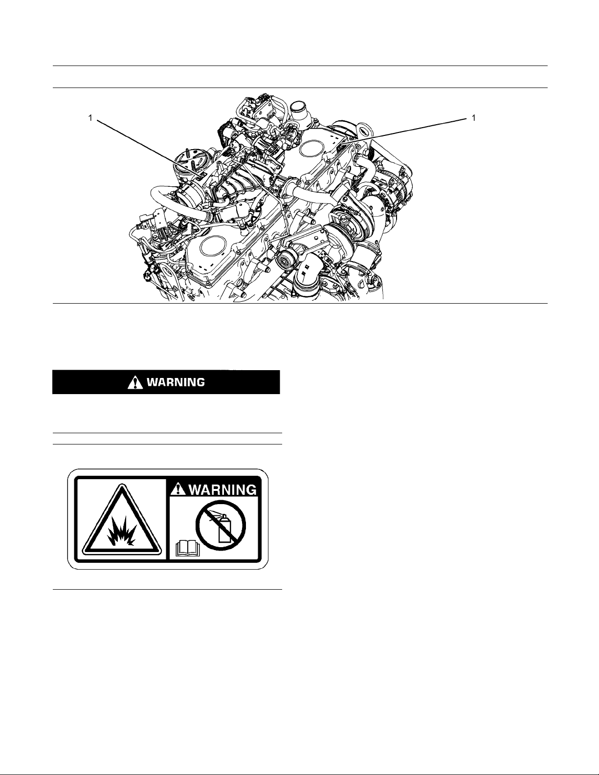
The Universal W
positions. The warning labels are located on the front
right side of the valve mechanism cover and located
on the top of th
arning label (1) is located in two
e NOx reduction system NRS.
(1) Universal Warning
Do not operate or work on this equipment unless
ave read and understand the instructions
you h
and warnings in the Operation and Maintenance
Manuals. Failure to follow the instructions or
the warnings could result in serious injury
heed
or death.
Illustration 1
ypical example
T
g01154807
Page 6
6 SEBU8601-01
Safety Section
Safety Messages
Illustration 2
(1) Universal warning
(2) Ether
Do not use aerosol types of starting aids such as
ether. Such use could result in an explosion and
personal injury.
g02305279
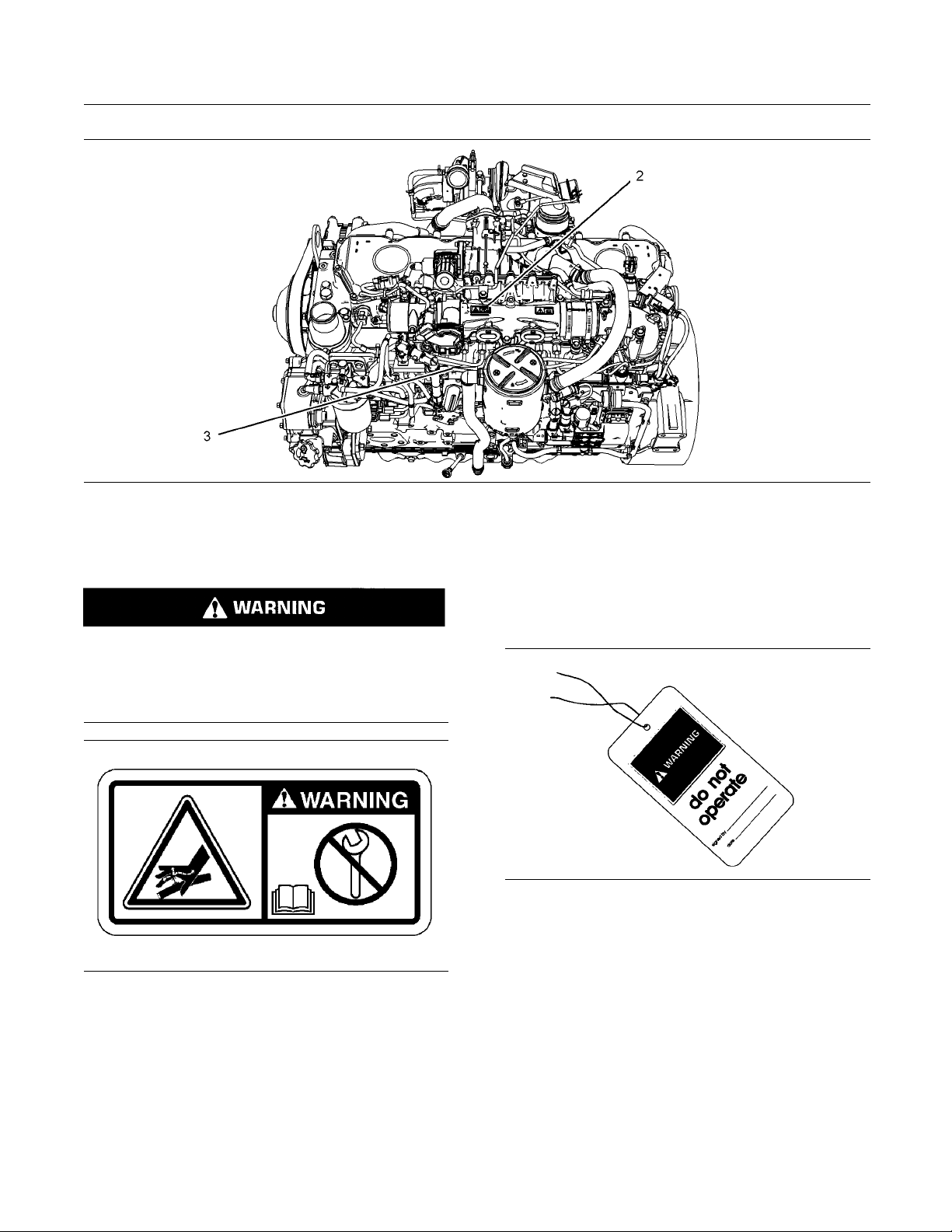
Illustration 3
Typical example
g01154809
The ether warning label (2) is located on the top of
thereductionsystem(NRS).
Page 7
SEBU8601-01 7
Safety Section
General Hazard Information
Illustration 4
(2) Ether (3) Hand (High Pressure
(3) Hand (High Pressure)
Contact with high pressure fuel may cause fluid
penetration and burn hazards. High pressure fuel spray may cause a fire hazard. Failure to follow these inspe ction, maintenance and service instructions may cause personal injury or death.
Illustration 5
Typical example
g01154858
g02305282
i03566024
General Hazard Information
Illustration 6
Attach a “Do Not Operate” warning tag or a similar
warning tag to the start switch or to the controls
before the engine is serviced or before the engine is
repaired. Attach the warning tags to the engine and to
each operator control station. When it is appropriate,
disconnect the starting controls.
g00104545
The warning label for the Hand (High Pressure) (3) is
located on a high-pressure fuel line.
Do not allow unauthorized personnel on the engine,
or around the engine when the engine is being
serviced.
Tampering with the engine installation or tampering
•
with the OEM supplied wiring can be dangerous.
Personal injury, death and/or engine damage could
result.
Page 8
8 SEBU8601-01
Safety Section
General Hazard Information
Vent the engine
•
engine is operated in an enclosed area.
If the engine i
•
secondary brake or the parking brake systems
unless the vehicle is blocked or unless the vehicle
is restraine
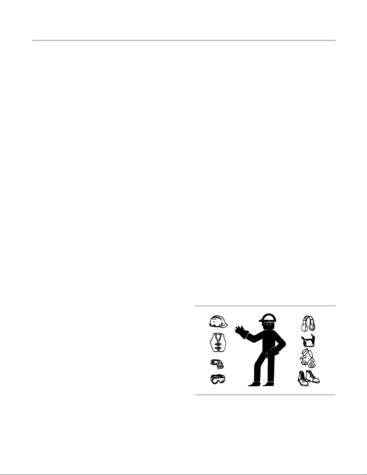
Wear a hard hat, protective glasses, and other
•
protective
When work is performed around an engine that is
•
operating,
to help prevent damage to hearing.
Do not wear
•
on controls or on other parts of the engine.
Ensure tha
•
securedinplaceontheengine.
Never put
•
Glass containers can break.
Use all cl
•
Report all necessary repairs.
•
eaning solutions with care.
exhaust to the outside when the
s not running, do not release the
d.
equipment, as required.
wear protective devices for ears in order
loose clothing or jewelry that can snag
t all protective guards and all covers are
maintenance fluids into glass containers.
For initial sta
•
engine that has been serviced, make provisions to
stop the engine if an overspeed occurs. This may
be accomplish
and/or the air supply to the engine.
Start the eng
•
Never short across the starting motor terminals or
the batteries. This could bypass the engine neutral
start syste
damaged.
Engine exha
which may be harmful to your health. Always start the
engine and operate the engine in a well ventilated
area. If th
engine exhaust to the outside.
Cautiousl
prevent spraying or splashing of pressurized fluids,
hold a rag over the part that is being removed.
Filler caps
•
Grease fit
•
Pressure taps
•
rt-up of a new engine or for starting an
ed by shutting off the fuel supply
ine from the operator's station (cab).
m and/or the electrical system could be
ust contains products of combustion
e engine is in an enclosed area, vent the
y remove the following parts. To help
tings
Unless other instructions are provided, perform the
maintenance under the following conditions:
The engine is stopped. Ensure that the engine can
•
not be started.
Theprotectivelocksorthecontrolsareinthe
•
applied position.
Engage the secondary brakes or parking brakes.
•
the vehicle or restrain the vehicle before
Block
•
maintenance or repairs are performed.
onnect the batteries when maintenance
Disc
•
is performed or when the electrical system is
serviced. Disconnect the battery ground leads.
the leads in order to help prevent sparks.
Ta p e
Disconnect the connector for the unit injector that
•
ocated on the valve cover base. This will help
is l
prevent personal injury from the high voltage to the
unit injectors. Do not come in contact with the unit
ector terminals while the engine is operating.
inj
Do not attempt any repairs or any adjustments to
•
e engine while the engine is operating.
th
Do not attempt any repairs that are not understood.
•
e the proper tools. Replace any equipment that
Us
is damaged or repair the equipment.
Breathers
•
Drain pl
•
Use caution when cover plates are removed.
Gradua
bolts or nuts that are located at opposite ends of
the cover plate or the device. Before removing the
last t
relieve any spring pressure or other pressure.
Illustration 7
Wear a hard hat, protective glasses, and other
•
protective equipment, as required.
When work is performed around an engine that is
•
operating, wear protective devices for ears in order
to help prevent damage to hearing.
ugs
lly loosen, but do not remove the last two
wo bolts or nuts, pry the cover loose in order to
g00702020
Page 9
SEBU8601-01 9
Safety Section
General Hazard Information
Do not wear loos
•
on controls or on other parts of the engine.
Ensure that al
•
securedinplaceontheengine.
Never put mai
•
Glass containers can break.
Use all clea
•
Report all necessary repairs.
•
Unless other instructions are provided, perform
the maintenance under the following conditions:
The engine is stopped. Ensure that the engine
•
cannot be started.
Disconnect the batteries when maintenance
•
is performed or when the electrical system is
serviced
Tape the leads in order to help prevent sparks.
Do not att
•
Use the proper tools. Replace any equipment that
is damaged or repair the equipment.
. Disconnect the battery ground leads.
empt any repairs that are not understood.
e clothing or jewelry that can snag
l protective guards and all covers are
ntenance fluids into glass containers.
ning solutions with care.
Illustration 8
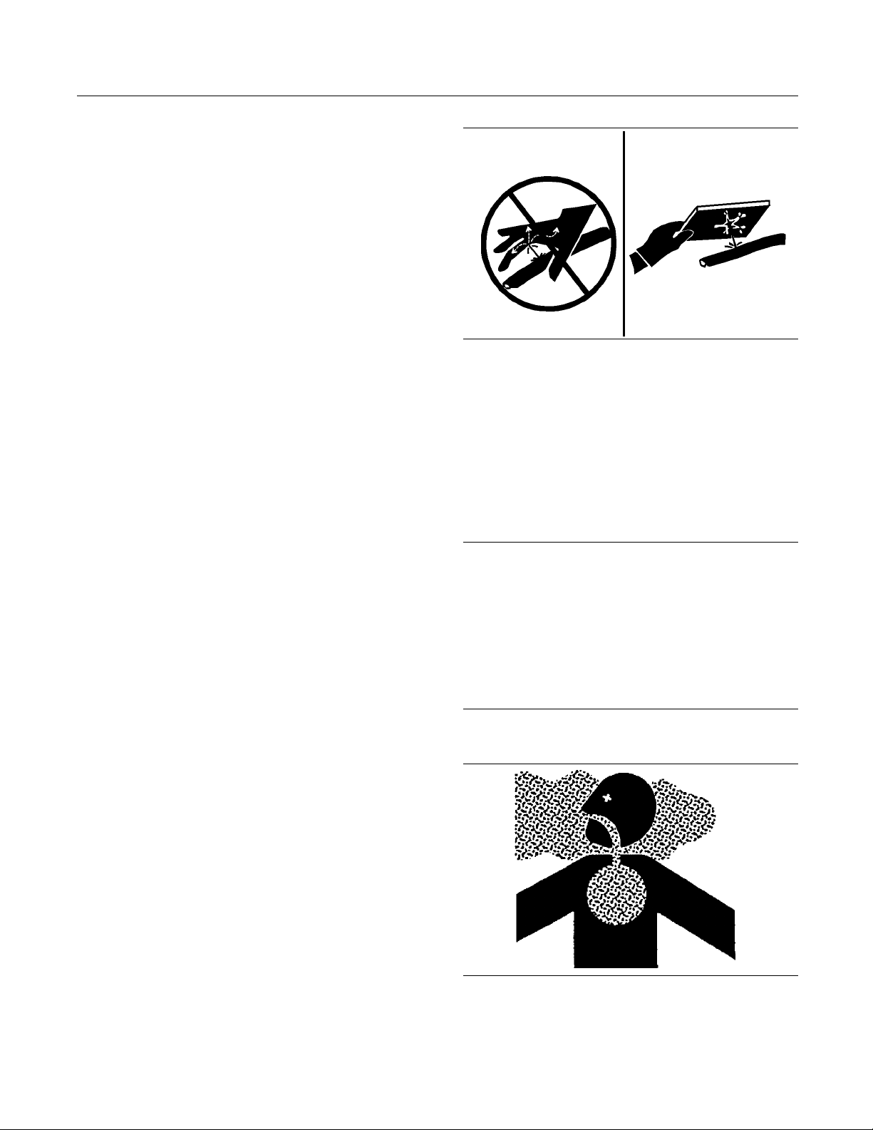
Always use a board or cardboard when you check
for a leak. Leaking fluid that is under pressure can
penetrate body tissue. Fluid penetration can cause
serious injury and possible death. A pin hole leak can
cause severe injury. If fluid is injected into your skin,
you must get treatment immediately. Seek treatment
from a doctor that is familiar with this type of injury.
g00687600
Containing Fluid Spillage
Pressurized Air and Water
Pressurized air and/or water can cause debris
and/or hot water to be blown out. This could result in
person
When pressurized air and/or pressurized water is
used f
shoes, and eye protection. Eye protection includes
goggles or a protective face shield.
The maximum air pressure for cleaning purposes
must be below 205 kPa (30 psi). The maximum
wate
275kPa(40psi).
al injury.
or cleaning, wear protective clothing, protective
r pressure for cleaning purposes must be below
Fluid Penetration
sure can be trapped in the hydraulic circuit long
Pres
after the engine has been stopped. The pressure can
cause hydraulic fluid or items such as pipe plugs to
ape rapidly if the pressure is not relieved correctly.
esc
Do not remove any hydraulic components or parts
il pressure has been relieved or personal injury
unt
may occur. Do not disassemble any hydraulic
components or parts until pressure has been relieved
personal injury may occur. Refer to the OEM
or
information for any procedures that are required to
relieve the hydraulic pressure.
NOTICE
Care must be taken to ensure that fluids are contained
during performance of inspection, maintenance, testing, adjusting and repair of the product. Be prepared to
collect the fluid with suitable containers before opening any compartment or disassembling any component containing fluids.
Dispose of all fluids according to local regulations and
mandates.
Asbestos Information
Illustration 9
g00702022
Page 10

10 SEBU8601-01
Safety Section
Burn Prevention
Perkins replac
Perkins are asbestos free. Perkins recommends
the use of only genuine Perkins replacement parts.
Use the follow
replacement parts that contain asbestos or when you
handle asbestos debris.
Use caution. Avoid inhaling dust that might be
generated when you handle components that contain
asbestos fib
to your health. The components that may contain
asbestos fibers are brake pads, brake bands, lining
material, c
asbestos that is used in these components is usually
boundinaresinorsealedinsomeway.Normal
handling i
contains asbestos is generated.
If dust tha
are several guidelines that should be followed:
Never use
•
Avoid brushing materials that contain asbestos.
•
Avoid grinding materials that contain asbestos.
•
ement parts that are shipped from
ing guidelines when you handle any
ers. Inhaling this dust can be hazardous
lutch plates, and some gaskets. The
s not hazardous unless airborne dust that
t may contain asbestos is present, there
compressed air for cleaning.
Dispose of Waste Properly
Illustration 10
Improperly disposing of waste can threaten the
environment. Potentially harmful fluids should be
dispose
Always use leakproof containers when you drain
fluids. D
drain, or into any source of water.
d of according to local regulations.
o not pour waste onto the ground, down a
g0070640
4
Use a wet
•
materials.
A vacuum
•
efficiency particulate air filter (HEPA) can also be
used.
Use exhaust ventilation on permanent machining
•
jobs.
Wear an approved respirator if there is no other
•
way to control the dust.
Comply with applicable rules and regulations
•
for the work place. In the United States, use
Occu
(OSHA) requirements. These OSHA requirements
can be found in “29 CFR 1910.1001”.
Obey environmental regulations for the disposal
•
of asbestos.
Stay away from areas that might have asbestos
•
particles in the air.
method in order to clean up asbestos
cleaner that is equipped with a high
pational Safety and Health Administration
i04156653
Burn Prevention
Do not touch any part of an operating engine
system. The engine, the exhaust, and the engine
aftertreatment system can reach temperatures as
high as 650 °C (1202 °F) under normal operating
conditions. If the engine or the engine aftertreatment
system unexpectedly fails, the temperature of the
gas at the diesel particulate filter (DPF) may increase
to 900°C (1652°F).
At idle engine speed and/or zero vehicle speed,
an operator can request a manual regeneration.
Under this condition, the exhaust gas temperature
can reach 650 °C (1202 °F). Otherwise automatic
regeneration can produce exhaust gas temperatures
as high as 450 °C (842 °F).
Allow the engine system to cool before any
maintenance is performed. Relieve all pressure
in the air system, in the hydraulic system, in the
lubrication system, in the fuel system, or in the
cooling system before any lines, fittings, or related
items are disconnected.
Page 11
SEBU8601-01 11
Safety Section
Fire Prevention and Explosion Prevention
Contact with high pressure fuel may cause fluid
penetration and burn hazards. High pressure fuel spray may cause a fire hazard. Failure to follow these inspe ction, maintenance and service instructions may cause personal injury or death.
After the engine has stopped, you must wait for 10
minutes in order to allow the fuel pressure to be
purged from the high-pressure fuel lines before any
service or repair is performed on the engine fuel lines.
Allow the pressure to be purged in the air system, in
the hydraulic system, in the lubrication system, or
in the cooling system before any lines, fittings, or
related items are disconnected.
Induction System
Sulfuric Acid Burn Hazard may cause serious personal injury or death.
The exhaust gas cooler may contain a small
amount of sulfuric acid. The use of fuel with sulfur levels greater than 15 ppm may increase the
amount of sulfuric acid formed. The sulfuric acid
may spill from the cooler during service of the
engine. The sulfuric acid will burn the eyes, skin
and clothing on contact. Always wear the a ppropriate personal protective equipment (PPE) that
is noted on a material safety data sheet (MSDS)
for sulfuric acid. Always follow the directions for
first aid that are noted on a material safety data
sheet (MSDS) for sulfuric acid.
Cooling system
cause personal injury. Do not allow alkali to contact
the skin, the eyes, or the mouth.
conditioner contains alkali. Alkali can
Oils
Hot oil and hot lubricating components can cause
personal injury. Do not allow hot oil to contact the
skin. Also, d
the skin.
o not allow hot components to contact
Batteries
Electrolyt
injury. Do not allow electrolyte to contact the skin or
the eyes. Always wear protective glasses for servicing
batteries
and connectors. Use of gloves is recommended.
e is an acid. Electrolyte can cause personal
. Wash hands after touching the batteries
i03652933
Fire Prevention an d Explosion
Prevention
Coolant
When the engine is at operating temperature, the
engine coolant is hot. The coolant is also under
pressure. The radiator and all lines to the heaters or
to the engine contain hot coolant. The aftertreatment
regeneration device (ARD) is connected to the
coolant system and will contain hot coolant.
Any contact with hot coolant or with steam can cause
severe burns. Allow cooling system components to
cool before the cooling system is drained.
Check that the coolant level after the engine has
stopped and the engine has been allowed to cool.
Ensure that the filler cap is cool before removing the
filler cap. The filler cap must be cool enough to touch
withabarehand.Removethefiller cap slowly in
order to relieve pressure.
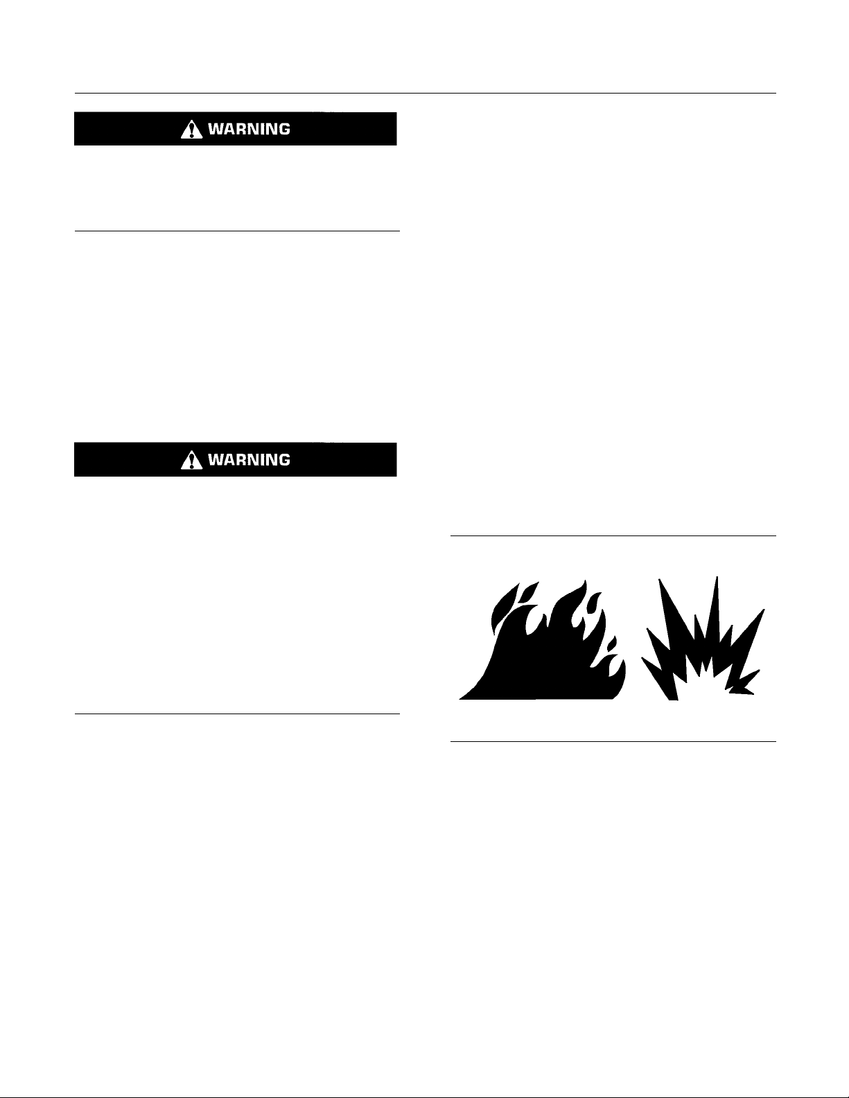
Illustration 11
All fuels, most lubricants, and some coolant mixtures
are fl ammable.
Flammable fluids that are leaking or spilled onto hot
surfaces or onto electrical components can cause
a fire. Fire may cause personal injury and property
damage.
After the emergency stop button is operated ensure
that you allow 15 minutes, before the engine covers
are removed.
Determinewhethertheenginewillbeoperatedinan
environment that allows combustible gases to be
drawn into the air inlet system. These gases could
cause the engine to overspeed. Personal injury,
property damage, or engine damage could result.
g00704000
Page 12
12 SEBU8601-01
Safety Section
Fire Prevention and Explosion Prevention
If the applicat
ion involves the presence of combustible
gases, consult your Perkins dealer and/or your
Perkins distributor for additional information about
suitable prot
ection devices.
Remove all flammable combustible materials or
conductive m
aterials such as fuel, oil, and debris from
the engine. Do not allow any flammable combustible
materials or conductive materials to accumulate on
the engine.
Store fuels and lubricants in correctly marked
containers
away from unauthorized persons. Store
oily rags and any flammable materials in protective
containers. Do not smoke in areas that are used for
storing fla
mmable materials.
Do not expose the engine to any flame.
Exhaust shields (if equipped) protect hot exhaust
components from oil or fuel spray in case of a line,
a tube, or
a seal failure. Exhaust shields must be
installed correctly.
Do not wel
d on lines or tanks that contain flammable
fluids. Do not flame cut lines or tanks that contain
flammable fluid. Clean any such lines or tanks
thoroug
hly with a nonflammable solvent prior to
welding or flame cutting.
Ensure that the
engine is stopped. Inspect all lines
and hoses for wear or for deterioration. The hoses
must be correctly routed. The lines and hoses must
have adequate
support and secure clamps.
Oil filters and fuel filters must be correctly installed.
The filter hou
sings must be tightened to the correct
torque. Refer to the Disassembly and Assembly
manual for more information.
Wiring m
ust be kept in good condition. All electrical
wires must be correctly routed and securely attached.
Check all electrical wires daily. Repair any wires
e loose or frayed before you operate the
that ar
engine. Clean all electrical connections and tighten
all electrical connections.
Eliminate all wiring that is unattached or unnecessary.
Do not use any wires or cables that are smaller than
commended gauge. Do not bypass any fuses
the re
and/or circuit breakers.
ng or sparking could cause a fire. Secure
Arci
connections, recommended wiring, and correctly
maintained battery cables will help to prevent arcing
arking.
or sp
Contact with high pressure fuel may cause fluid
penetration and burn hazards. High pressure fu-
spray may cause a fire hazard. Failure to fol-
el
low these inspe ction, maintenance and service instructions may cause personal injury or death.
After the engine has stopped, you must wait for 10
minutes in order to allow the fuel pressure to be
urged from the high pressure fuel lines before any
p
service or repair is performed on the engine fuel lines.
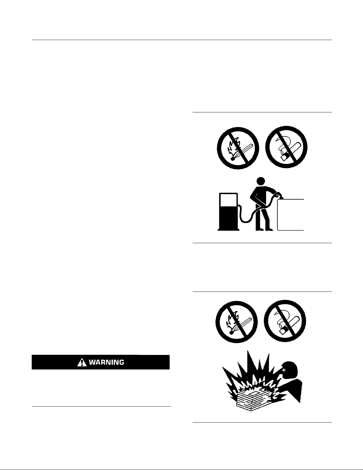
Illustration 12
g00704059
Use caution when you are refueling an engine. Do
not smoke while you are refueling an engine. Do not
refuel an engine near open flames or sparks. Always
stop the engine before refueling.
Illustration 13
g00704135
Page 13

SEBU8601-01 13
Safety Section
Crushing Prevention and Cutting Prevention
Gases from a bat
flames or sparks away from the top of a battery. Do
not smoke in battery charging areas.
Never check the battery charge by placing a metal
object across the terminal posts. Use a voltmeter or
ahydrometer
Incorrect jumper cable connections can cause
an explosio
the Operation Section of this manual for specific
instructions.
Do not charge a frozen battery. This may cause an
explosion.
The batteries must be kept clean. The covers
(if equipped) must be kept on the cells. Use the
recommend
covers when the engine is operated.
tery can explode. Keep any open
.
n that can result in injury. Refer to
ed cables, connections, and battery box
Fire Extinguisher
Make sure
familiar with the operation of the fire extinguisher.
Inspect the fire extinguisher and service the fire
extingu
on the instruction plate.
that a fire extinguisher is available. Be
isher regularly. Obey the recommendations
i02143194
Crushing Prevention and
Cutting Preve
Support the component correctly when work beneath
the component is performed.
Unless other maintenance instructions are provided,
never attempt adjustments while the engine is
running.
Stay clear of all rotating parts and of all moving
parts. Lea
is performed. After the maintenance is performed,
reinstall the guards.
Keep objects away from moving fan blades. The fan
blades will throw objects or cut objects.
When objects are struck, wear protective glasses in
order to avoid injury to the eyes.
Chips or other debris may fly off objects when objects
are struck. Before objects are struck, ensure that no
one will
ve the guards in place until maintenance
be injured by flying debris.
ntion
Lines, Tubes and Hoses
Do not b
pressure lines. Do not install any lines that are
damaged.
Leaks can cause fires. Consult your Perkins dealer
or your Perkins distributor for replacement parts.
Replace the parts if any of the following conditions
are present:
•
•
•
•
•
•
•
•
Make sure that all clamps, guards, and heat shields
ar
will help to prevent vibration, rubbing against other
parts, and excessive heat.
end high pressure lines. Do not strike high
High pressure fuel line or lines are removed.
ttings are damaged or leaking.
End fi
Outer coverings are chafed or cut.
Wires are exposed.
er coverings are ballooning.
Out
Flexible part of the hoses are kinked.
Outer covers have embedded armoring.
d fittings are displaced.
En
e installed correctly. During engine operation, this
i04016709
Mounting and Dismounting
Do not climb on the engine or the engine
aftertreatment. The engine and aftertreatment have
not been designed with mounting or dismounting
locations.
Refer to the OEM for the location of foot and hand
holds for your specific application.
i03550790
h Pressure Fuel Lines
Hig
Contact with high pressure fuel may cause fluid
enetration and burn hazards. High pressure fu-
p
el spray may cause a fire hazard. Failure to follow these in spection, maintenance and service in-
tructions may cause personal injury or death.
s
Page 14
14 SEBU8601-01
Safety Section
High Pressure Fuel Lines
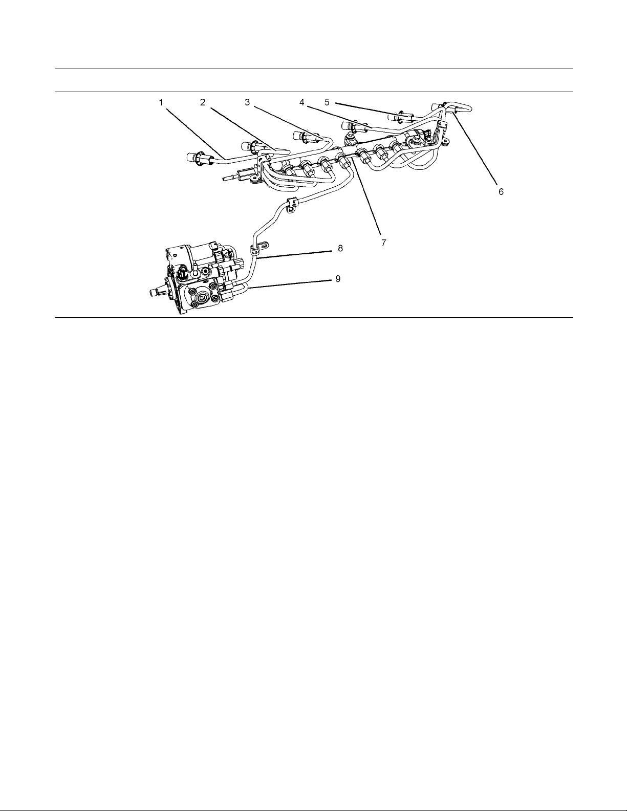
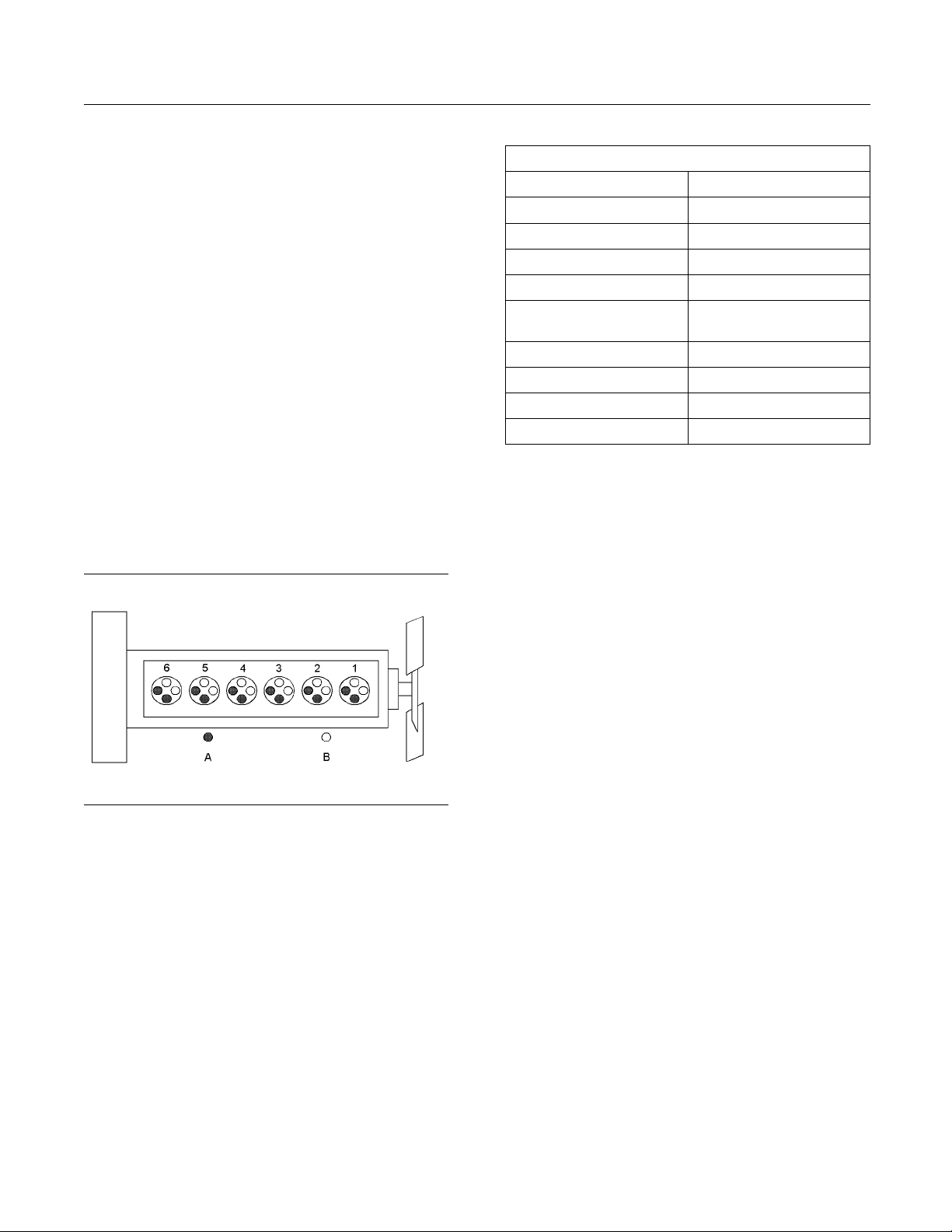
Illustration 14
(1)Highpressureline
(2)Highpressureline
(3)Highpressureline
(4) H ig h press u re line
(5) H ig h press u re line
(6) H ig h press u re line
The high pressure fuel lines are the fuel lines that
are between the high pressure fuel pump and the
high pressure fuel manifold and the fuel lines that are
between the fuel manifold and cylinder head. These
fuel lines are different from fuel lines on other fuel
systems.
This is because of the following items:
The high pressure fuel lines are constantly charged
•
with high pressure.
The internal pressures of the high pressure fuel
•
lines are higher than other types of fuel system.
The high pressure fuel lines are formed to shape
•
and then strengthened by a special process.
Do not step on the high pressure fuel lines. Do not
deflect the high pressure fuel lines. Do not bend or
strike the high pressure fuel lines. Deformation or
damage of the high pressure fuel lines may cause a
point of weakness and potential failure.
Do not check the high pressure fuel lines with the
engine or the starting motor in operation. After the
engine has stopped, you must wait for 10 minutes in
order to allow the fuel pressure to be purged from the
high pressure fuel lines before any service or repair
is performed on the engine fuel lines.
Do not loosen the high pressure fuel lines in order
to remove air from the fuel system. This procedure
is not required.
g01877473
(7) High pressure fuel manifold (rail)
(8) High pressure line
(9) Fuel transfer line that is high pressure
Visually inspect the high pressure fuel lines before
the engine is started. This inspection should be each
day.
If you inspect the engine in operation, always use
the proper inspection procedure in order to avoid
a fluid penetration hazard. Refer to Operation and
Maintenance Manual, “General hazard Information”.
Inspect the high pressure fuel lines for damage,
•
deformation, a nick, a cut, a crease, or a dent.
Donotoperatetheenginewithafuelleak.Ifthere
•
is a leak do not tighten the connection in order
to stop the leak. The connection must only be
tightened to the recommended torque. Refer to
Disassembly and Assembly, “Fuel injection lines Remove and Fuel injection lines - Install”.
Ifthehighpressurefuellinesaretorquedcorrectly
•
and the high pressure fuel lines are leaking the
high pressure fuel lines must be replaced.
Ensure that all clips on the high pressure fuel lines
•
are in place. Do not operate the engine with clips
that are damaged, missing or loose.
Do not attach any other item to the high pressure
•
fuel lines.
Loosened high pressure fuel lines must be
•
replaced. Also removed high pressure fuel lines
must be replaced. Refer to Disassembly and
assembly manual, “ Fuel Injection Lines - Install”.
Page 15

SEBU8601-01 15
Safety Section
Before Starting Engine
i02813489
Before Starting Engine
Before the ini
serviced or repaired, make provision to shut the
engine off, in order to stop an overspeed. This may
be accomplis
supply to the engine.
Overspeed s
engines that are controlled electronically. If automatic
shutdown does not occur, press the emergency stop
buttonino
Inspect the engine for potential hazards.
Before starting the engine, ensure that no one is on,
underneath, or close to the engine. Ensure that the
area is fr
If equipped, ensure that the lighting system for the
engine is
lights work correctly, if equipped.
All prot
be installed if the engine must be started in order
to perform service procedures. To help prevent an
acciden
around the parts carefully.
Do not b
disable the automatic shutoff circuits. The circuits are
provided in order to help prevent personal injury. The
its are also provided in order to help prevent
circu
engine damage.
See th
adjustments.
tial start-up of an engine that is new,
hed by shutting off the air and/or fuel
hutdown should occur automatically for
rder to cut the fuel and/or air to the engine.
ee of personnel.
suitable for the conditions. Ensure that all
ective guards and all protective covers must
t that is caused by parts in rotation, work
ypass the automatic shutoff circuits. Do not
e Service Manual for repairs and for
i03996487
Engine Starting
All protective
be installed if the engine must be started in order
to perform service procedures. T o help prevent an
accident that
around the parts carefully.
Start the eng
from the engine start switch.
Always star
that is described in the Operation and Maintenance
Manual, “Engine Starting” topic in the Operation
Section. Kn
to prevent major damage to the engine components.
Knowing that the procedure will also help to prevent
personal i
To ensure that the jacket water heater (if equipped)
and/or the
correctly, check the water temperature gauge. Also,
check the oil temperature gauge during the heater
operatio
Engine exhaust contains products of combustion
which can
engine and operate the engine in a well ventilated
area. If the engine is started in an enclosed area,
vent the
Note: The engine is equipped with a device for cold
g. If the engine will be operated in very cold
startin
conditions, then an extra cold starting aid may be
required. Normally, the engine will be equipped with
the cor
operation.
These
aid in each individual cylinder that heats the intake air
in order to improve starting. Some Perkins engines
may ha
the ECM that allows a controlled flow of ether into
the engine. The ECM will disconnect the glow plugs
re the ether is introduced. This system would
befo
be installed at the factory.
guards and all protective covers must
is caused by parts in rotation, work
ine from the operators compartment or
t the engine according to the procedure
owing that the correct procedure will help
njury.
lube oil heater (if equipped) is working
n.
be harmful to your health. Always start the
engine exhaust to the outside.
rect type of starting aid for your region of
engines are equipped with a glow plug starting
ve a cold starting system that is controlled by
Do not use aerosol types of starting aids such as
ether. Such use could result in an explosion and
personal injury.
If a warning tag is attached to the engine start switch,
or to the controls DO NOT start the engine or move
the controls. Consult with the person that attached
the warning tag before the engine is started.
i02234873
Engine St opp ing
Stop the engine according to the procedure in
the Operation and Maintenance Manual, “Engine
Stopping (Operation Section)” in order to avoid
overheating of the engine and accelerated wear of
the engine components.
Page 16
16 SEBU8601-01
Safety Section
Electrical System
Use t he Emergen
cy Stop Button (if equipped) ONLY
in an emergency situation. Do not use the Emergency
Stop Button for normal engine stopping. After an
emergency sto
p, DO NOT start the engine until the
problem that caused the emergency stop has been
corrected.
Stop the engine if an overspeed condition occurs
during the initial start-up of a new engine or an engine
that has bee
n overhauled.
To stop an electronically controlled engine, cut the
power to the
engine and/or shutting off the air supply
to the engine.
i03903127
Electrical System
Never disconnect any charging unit circuit or battery
circuit cable from the battery when the charging unit
is operating. A spark can cause the combustible
gases that are produced by some batteries to ignite.
Grounding Practices
To help prevent sparks from igniting combustible
gases that are produced by some batteries, the
negative “−” cable should be connected last from
the external power source to the primary position for
grounding.
Check the electrical wires daily for wires that
are loose or frayed. Tighten all loose electrical
connections before the engine is started. Repair all
frayed electrical wires before the engine is started.
See the Operation and Maintenance Manual for
specific starting instructions.
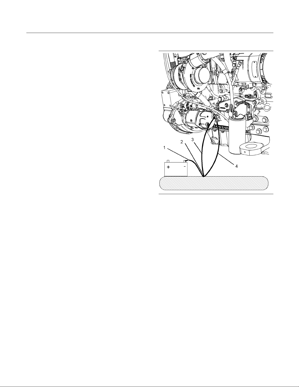
Illustration 15
Typical examp le
(1) Ground to the battery
(2) Primary position for grounding
(3) Ground to the starting motor
(4) Ground to the eng ine block
g02145392
Page 17
SEBU8601-01 17
Safety Section
Engine Electronics
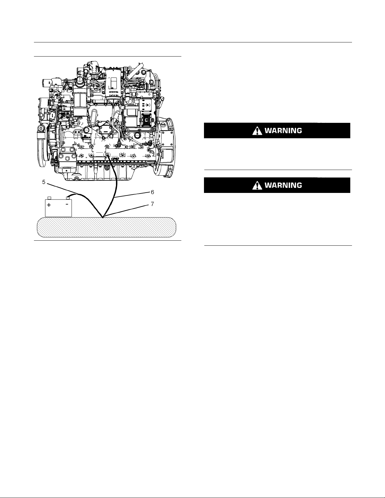
Illustration 16
example
Typical
(5) Ground to the battery
(6) G round to the engine block
(7) Primary position for grounding
Correct grounding for the engine electrical system
is necessary for optimum engine performance
liability. Incorrect grounding will result in
and re
uncontrolled electrical circuit paths and in unreliable
electrical circuit paths.
g02145733
The power suppl
connections for the engine electronics should always
be from the isolator to the battery.
y connections and the ground
i03642610
Engine Electro nics
Tampering with the electronic system installation
or the OEM wiring installation can be dangerous
andcouldr
engine damage.
Electrical Shock Hazard. The electronic unit injectors use DC voltage. The ECM sends this voltage
to the electronic unit injectors. Do not come in
contact with the harness connector for the electronic unit injectors while the engine is operating.
Failure to follow this instruction could result in
personal injury or death.
This engine has a comprehensive, programmable
Engine Monitoring System. The Electronic Control
Module (ECM) has the ability to monitor the engine
operating conditions. If any of the engine parameters
extend outside an allowable range, the ECM will
initiate an immediate action.
The following actions are available for engine
monitoring control:
esult in personal injury or death and/or
Uncontrolled electrical circuit paths can result in
damage to the crankshaft bearing journal surfaces
o aluminum components.
and t
Engines that are installed without engine-to-frame
nd straps can be damaged by electrical
grou
discharge.
nsure that the engine and the engine electrical
To e
systems function correctly, an engine-to-frame
ground strap with a direct path to the battery must be
d. This path may be provided by way of a direct
use
engine ground to the frame.
e connections for the grounds should be tight and
Th
free of corrosion. The engine alternator must be
grounded to the negative “-” battery terminal with
ire that is adequate to handle the full charging
aw
current of the alternator.
Warning
•
Derate
•
Shutdown
•
The following monitored engine operating conditions
have the ability to limit engine speed and/or the
engine power:
Engine Coolant Temperature
•
Engine Oil Pressure
•
Engine Speed
•
Intake Manifold Air Temperature
•
Engine Intake Throttle Valve Fault
•
Wastegate Regulator
•
Page 18

18 SEBU8601-01
Safety Section
Engine Electronics
Supply Voltage
•
Fuel Pressure in Manifold (Rail)
•
NOx Reduction System
•
Engine After
•
The Engine Monitoring package can vary for different
engine mode
However, the monitoring system and the engine
monitoring control will be similar for all engines.
Note: Many of the engine control systems and display
modules that are available for Perkins Engines will
work in uni
Together, the two controls will provide the engine
monitoring function for the specific engine application.
Refer to Tr
Engine Monitoring System.
son with the Engine Monitoring System.
oubleshooting for more information on the
to Sensors
treatment System
ls and different engine applications.
Page 19

SEBU8601-01 19
Product Information Section
Model Views
Product Information
Section
Model Views
i03913230
Model View Illustrations
The following model views show typical features
of the engine. Due to individual applications, your
engine may appear different from the illustrations.
Note: Only major components are identified on the
following illustrations.
Page 20
20 SEBU8601-01
Product Information Section
Model Views
Engine views
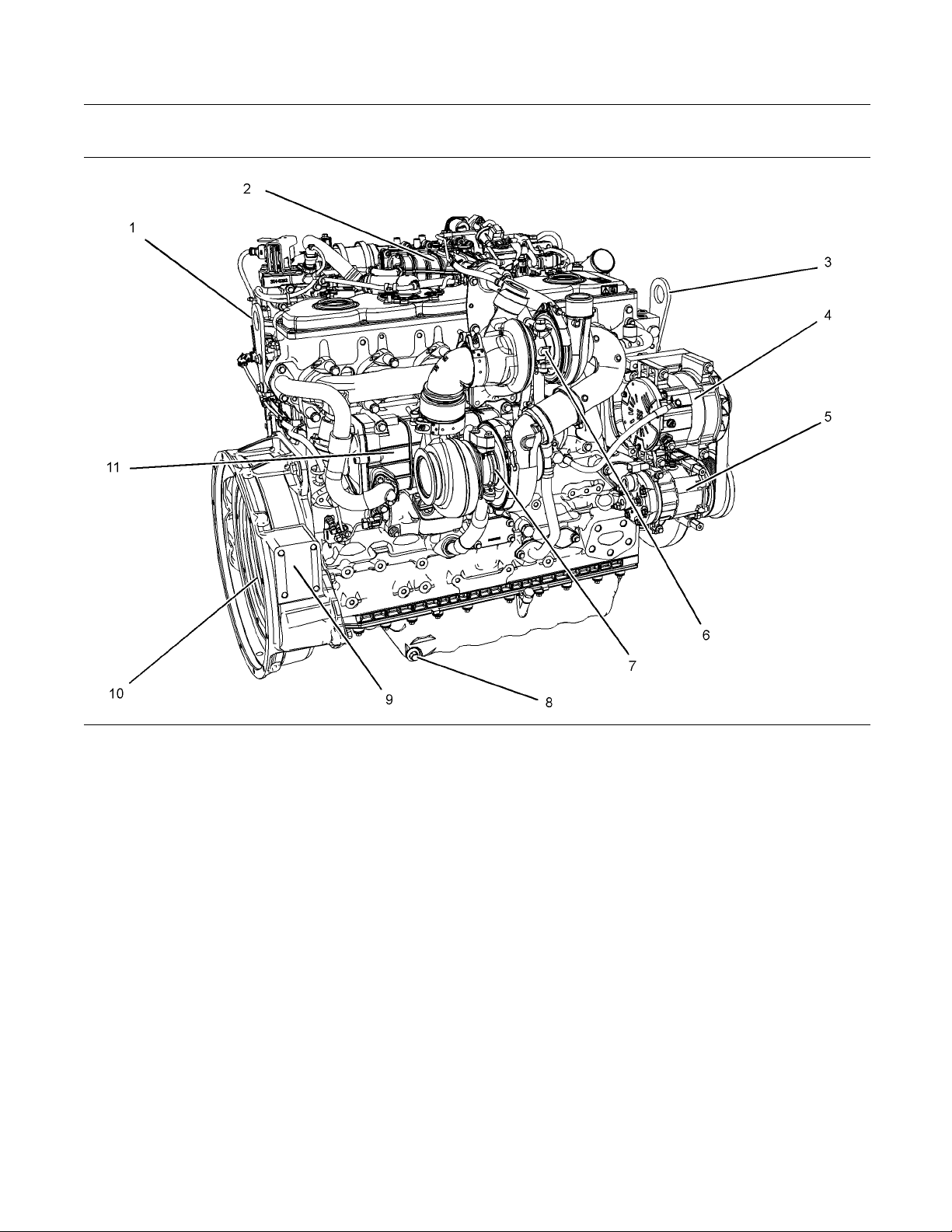
Illustration 17
Typical example
(1) Rear lifting eye
(2) NOx reduction system NRS
(3) Front lifting eye
(4) Alternator
(5) Refrigerant compressor
(6) High-pressure turbocharger
(7) Low-pressure turbocharger
(8) Engine oil drain
g02150184
(9) Flywheel housing
(10) Flywheel
(11) NRS cooler
Page 21
SEBU8601-01 21
Product Information Section
Model Views
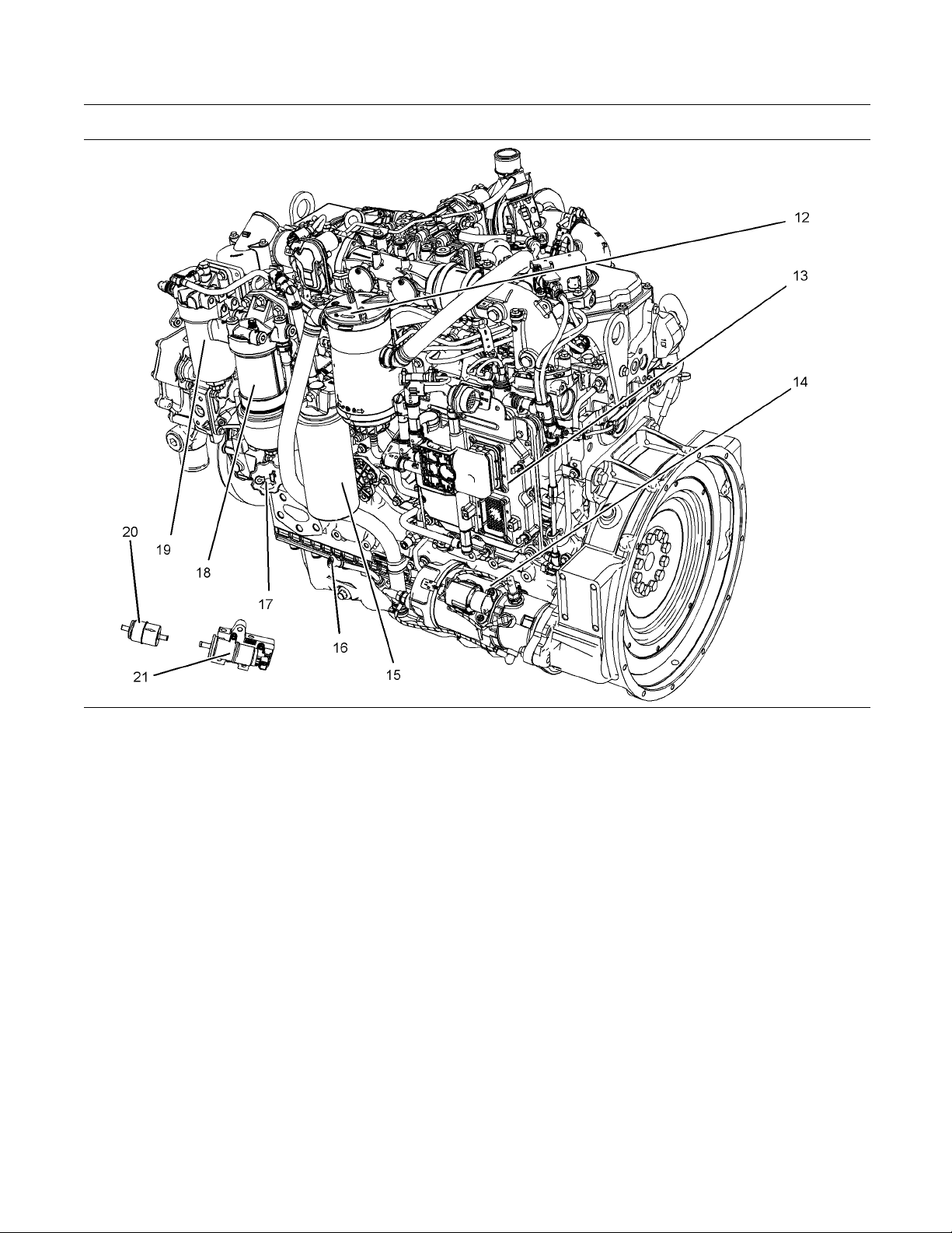
Illustration 18
Typical example
(12) Crankcase breather
(13) Electronic con trol module (ECM )
(14) Starting motor
(15) Oil filter
(16) Oil gauge
(17) Oil filler
(18) Primary fuel filter
(19) Secondary fuel filter
The location of the in-line fuel strainer (20) and the
priming pump (21) will depend on the application.
g02150185
(20) In-line fuel strainer
(21) Electric fuel priming pump
Page 22
22 SEBU8601-01
Product Information Section
Model Views
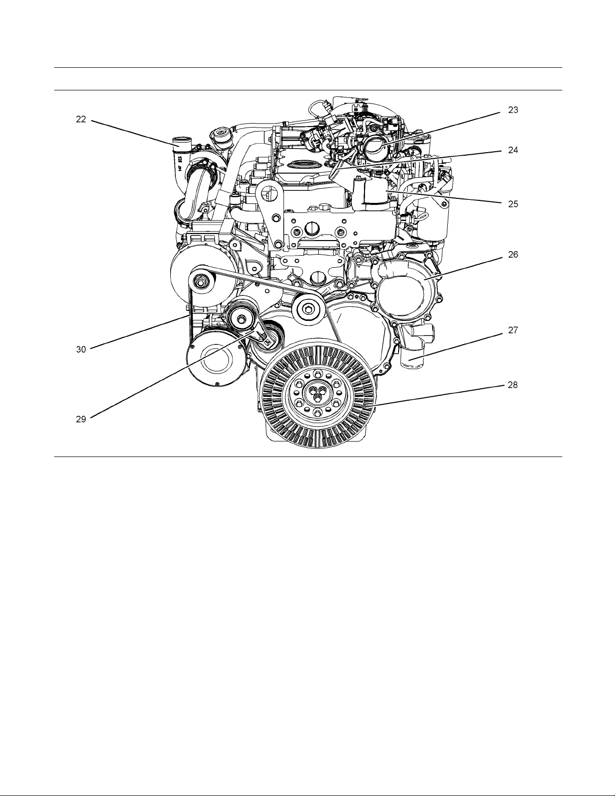
Illustration 19
Typical example
(22) Outlet connection to the air to air charge
cooler
(23) Connection for the air inlet
(24) Outlet c onnection for the coolant
(25) Housing for the water temperature
regulator
(26) Water pump
(27) Inlet connection for the Coolant
Engine Aftertreatment System
The following view shows typical features of the
engine aftertreatment system. Due to individual
applications, your system may appear different from
the illustrations.
g02150187
(28) Vibration damper
(29) Belt tensioner
(30) B elt
Page 23
SEBU8601-01 23
Product Information Section
Model Views
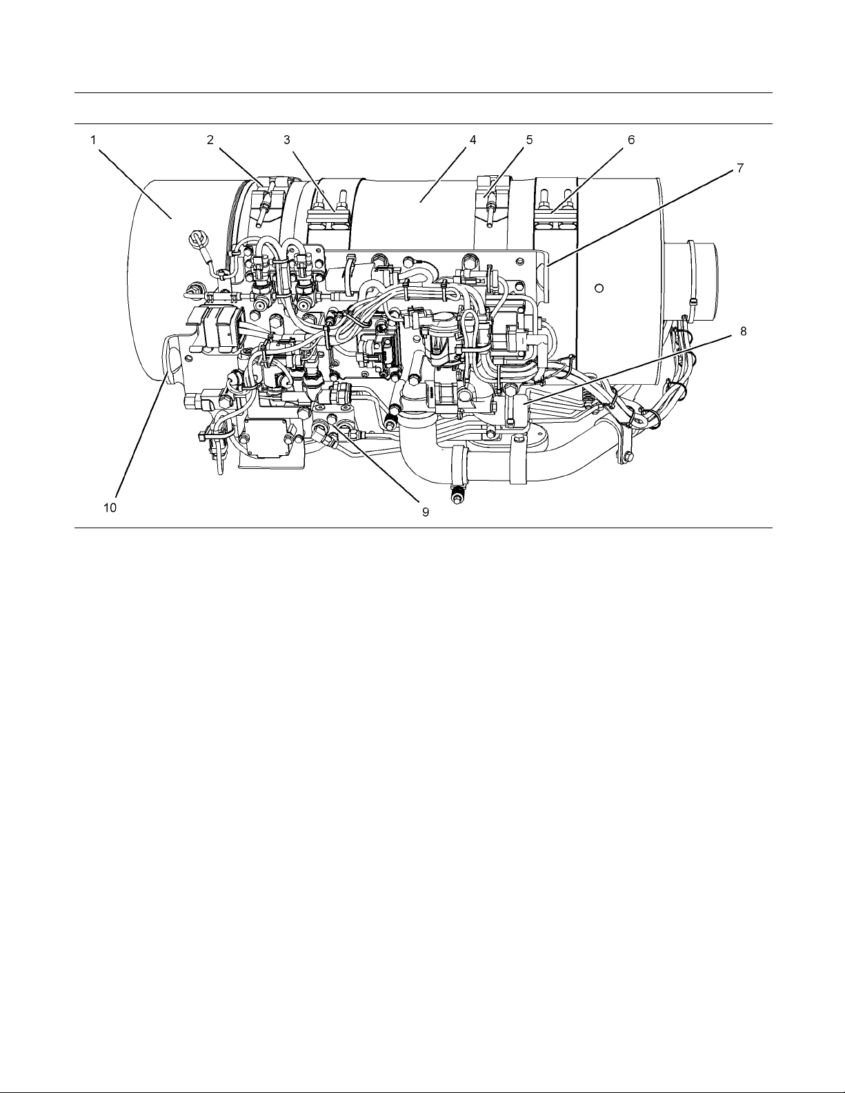
Illustration 20
example
Typical
(1) Diesel oxidation catalyst (DOC)
(2) Sec uring clamp
(3) Torca clamp
(4) Diesel particulate filter (DPF)
(5) Sec uring clamp
(6) Torca cla mp
(7) Lifting eye
(8) Air inlet for aftertreatment regeneration
device (ARD)
(9) Connections for Coolant manifold
g02162626
(10) Lifting eye
Page 24
24 SEBU8601-01
Product Information Section
Model Views
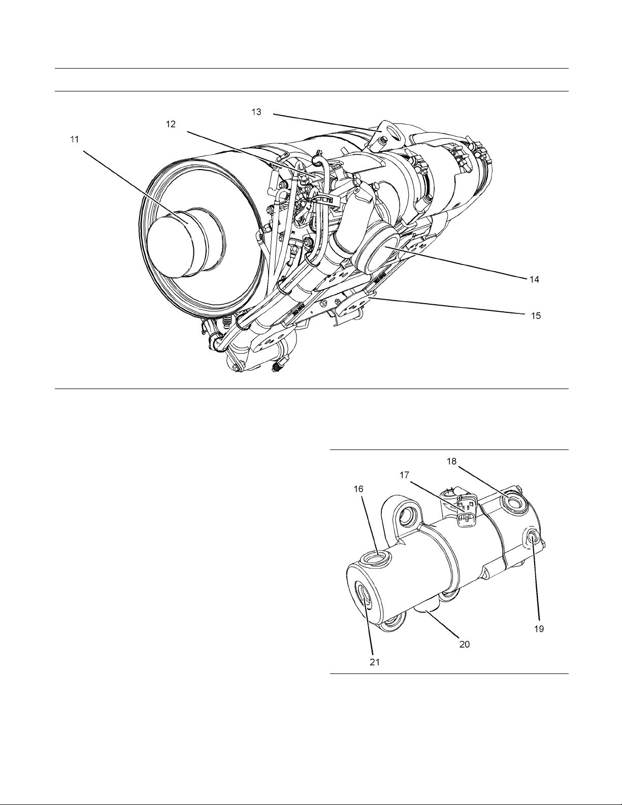
Illustration 21
let to exhaust system
(11) Out
ertreatment regeneration device
(12) Aft
(13) Lif
(14) Exh
ting eye
aust Inlet
Fuel Pump for Engine Aftertreatment
System
Note: The fuel for the engine aftertreatment system is
ied by a designated fuel pump. The location of
suppl
this pump can change depending on the application.
(15) Mou
Illustration 22
Typical examp le
(16) Fuel inlet
(17) Electrical connector
(18) Fuel supply line
(19) Return to tank
(20) Fuel inlet
(21) Fuel inlet
g02162641
nting cradle
g02163775
Page 25
SEBU8601-01 25
Product Information Section
Model Views
i03995541
Engine De script ion
The Perkins 12
following characteristics.
In-line 6 cyl
•
Four stroke cycle
•
Series turbocharged charge cooled
•
The 1206Ewith a low-pressure turbocharger and a high-pressure
turbocharger.
Engine Specifications
Note: The front end of the engine is opposite the
flywheel end of the engine. The left and the right
sides of t
end. The number 1 cylinder is the front cylinder.
06E-E70TTA industrial engine has the
inder
E70TTA industrial engine is equipped
he engine are determined from the flywheel
Table 1
1206E-E70TTA Engine Specifications
Operating Range (rpm) 900 to 2800
Number of Cylinders 6 In-Line
Bore
Stroke 135 mm (5.31495 inch)
Power
Aspiration Turbocharged charge
Compression Ratio 16.5:1
Displacement
Firing Order
Rotation (flywheel end) Counterclockwise
(1)
The operating rpm is dependent on the engine rating, the
application, and the configuration of the throttle.
105 mm (4.13
225 kW (301.72 hp)
cooled
7.01 L (42
1-5-3-6-2-4
(1)
inch)
8in3)
Electronic Engine Features
The engine operating conditions are monitored.
The Electronic Control Module (ECM) controls the
response of the engine to these conditions and to
the demands of the operator. These conditions and
operator demands determine the precise control of
fuel injection by the ECM. The electronic engine
control system provides the following features:
Illustration 23
Cylinder and valve location
(A) Exhaust valves
(B) Inlet valves
g01127295
Engine monitoring
•
Engine speed governing
•
Control of the injection pressure
•
Cold start strategy
•
Automatic air/fuel ratio control
•
Torque rise shaping
•
Injection timing control
•
System diagnostics
•
Aftertreatment Regeneration
•
For more information on electronic engine features,
refer to the Operation and Maintenance Manual,
“Features and Controls” topic (Operation Section).
Page 26

26 SEBU8601-01
Product Information Section
Model Views
Engine Diagnostics
Theenginehas
that the engine systems are functioning correctly. The
operator will be alerted to the condition by a “Stop or
Warning” lamp
horsepower and the vehicle speed may be limited.
The electronic service tool may be used to display
the diagnost
There are three types of diagnostic codes: active,
logged, and
Most of the diagnostic codes are logged and stored
in the ECM. F
the Operation and Maintenance Manual, “Engine
Diagnostics” topic (Operation Section).
The ECM provides an electronic governor that
controls the injector output in order to maintain the
desired e
Engine Co
The cooling system and lubrication system consists
of the fo
•
llowing components:
Gear-driven centrifugal water pump
built-in diagnostics in order to ensure
. Under certain conditions, the engine
ic codes.
event.
or additional information, refer to
ngine rpm.
oling and Lubrication
Expected engin
average power that is demanded. The average power
that is demanded is based on fuel consumption of
the engine ove
operation at full throttle and/or operating at reduced
throttle settings result in a lower average power
demand. Redu
the length of operating time before an engine
overhaul is required.
e life is generally predicted by the
r a period of time. Reduced hours of
ced hours of operation will increase
Aftermarket Products and Perkins
Engines
Perkins doe
of non-Perkins fluids and filters.
When auxil
(filters, additives, catalysts,) which are made by other
manufacturers are used on Perkins products, the
Perkins w
such use.
However,
or use of other manufacturers devices,
accessories, or consumables are NOT Perkins
defects
under the Perkins warranty.
s not warrant the quality or performance
iary devices, accessories, or consumables
arranty is not affected simply because of
failures that result from the installation
. Therefore, the defects are NOT covered
Water temperature regulator which regulates the
•
engine coolant temperature
Gear-driven rotor type oil pump
•
Oil coo
•
The engine lubricating oil is supplied by a rotor type
oil pu
engine lubricating oil is filtered. The bypass valve
can provide unrestricted flow of lubrication oil to
the en
plugged.
Engi
engine performance depend on adherence to proper
operation and maintenance recommendations.
Engi
the use of recommended fuels, lubrication oils, and
coolants. Refer to this Operation and Maintenance
Man
information on maintenance items.
ler
mp. The engine lubricating oil is cooled and the
gine if the oil filter element should become
ne efficiency, efficiency of emission controls, and
ne performance and efficiency also depend on
ual, “Maintenance Interval Schedule” for more
Engine Service Life
gine efficiency and maximum utilization of engine
En
performance depend on the adherence to proper
operation and maintenance recommendations. In
dition, use recommended fuels, coolants and
ad
lubricants. Use the Operation and Maintenance
Manual as a guide for required engine maintenance.
Aftertr
The aftertreatment system is approved for use by
Perkin
approved Perkins aftertreatment system must be
used on a Perkins engine.
eatment System
s. In order to be emission-compliant only the
Page 27
SEBU8601-01 27
Product Information Section
Product Identification Information
Product Identification
Information
Plate Locations and Film
Locations
i03567854
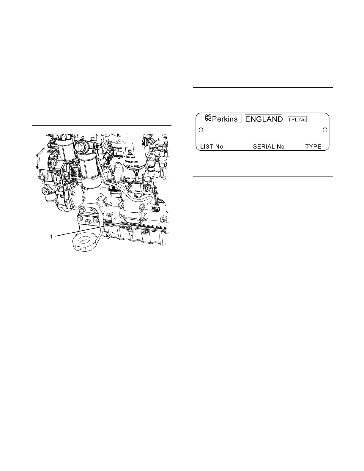
Serial Number Plate (1)
Theengineserialnumberplateislocatedonthe
left side of the cylinder block to the rear of the front
engine mounting.
tion 25
Illustra
Serial number plate
g01094203
Illustration 24
Location of the serial number plate
Perkins engines are identified by an engine serial
number.
An example of an engine number is BL*****U000001J.
*****
____________________ The list number for the engine
__________________________________________ Type of engine
BL
____________________________ Built in the United Kingdom
U
000001
J
Perkins dealers or Perkins distributors need all of
these numbers in order to determine the components
that were included with the engine. This permits
accurate identification of replacement part numbers.
The numbers for fuel setting information for electronic
engines are stored within the flash file. These
numbers can be read by using the electronic service
tool.
___________________________ Engine Serial Number
_____________________________________ Year of Manufacture
g01890033
Page 28
28 SEBU8601-01
Product Information Section
Product Identification Information
i03976148
Plate Locations and Film
Locations
(Engine Aftertreatment
System)
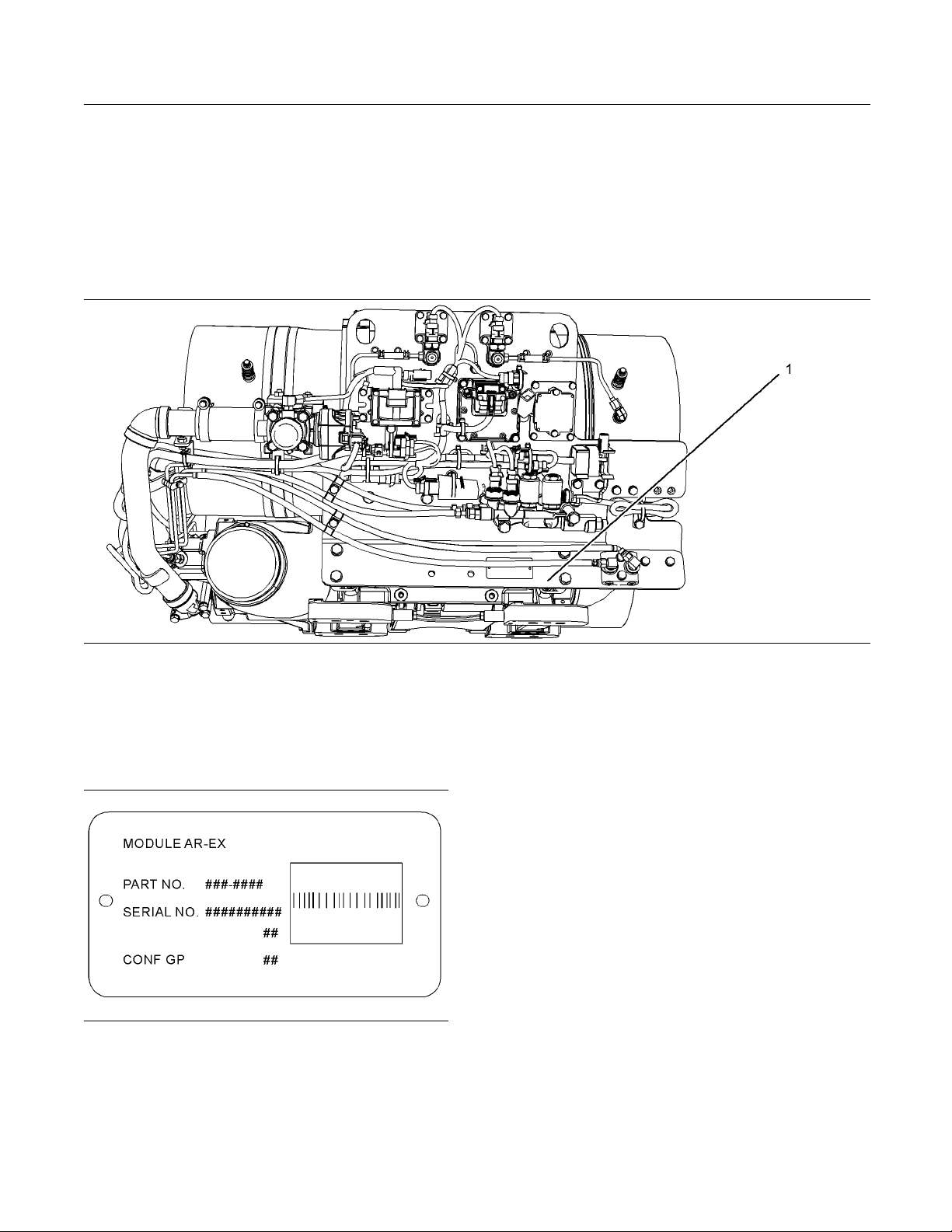
Illustration 26
Typical example
The module arrangement exhaust plate is installed
on the mounting plate (1). The location of the
arrangement plate mounting plate can alter
depending on the application.
Illustration 27
Module A rrangement Exhaust Plate
Record the information that is on the plate. This
information identifies the engine aftertreatment
system. This information will be required by your
Perkins dealer.
g02109493
g02151573
i03867276
Reference Numbers
Information for the following items may be needed to
order parts. Locate the information for your engine.
Record the information in the appropriate space.
Make a copy of this list for a record. Keep the
information for future reference.
Record for Reference
Engine Model _ ______________________________________________
Engine Serial number _____________________________________
Engine Low Idle rpm ______________________________________
Engine Full Load rpm _____________________________________
Primary Fuel Filter _________________________________________
Water Separator Element ________________________________
Secondary Fuel Filter Element __________________________
Page 29
SEBU8601-01 29
Product Information Section
Product Identification Information
Lubrication Oi
Auxiliary Oil Filter Element _______________________________
Total Lubrication System Capacity _____________________
Total Coolin
Air Cleaner Element _______________________________________
Drive Belt ____________________________________________________
Engine Afte
Part Number ________________________________________________
Serial Number _______ _______________________________________
l Filter Element
g System Capacity
rtreatment System
___________________________
_________________________
i03977815
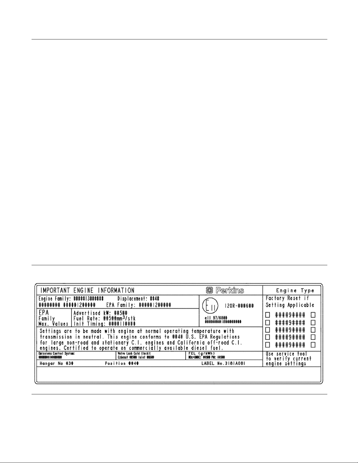
Emissions Certification Film
Label fo
r compliant engines
An emission label is installed on the front gear cover.
Note: A second emission label may be supplied with
the engine. If necessary, the second emission label
may be i
equipment manufacturer.
nstalled on the application by the original
Illustration 28
Typical example
g02164223
Page 30
30 SEBU8601-01
Operation Section
Lifting and Storage
Operation Section
Lifting and Storage
Product Lifting
(Engine)
i03977851
Some removals r
obtain correct balance and safety.
To r em ove th e e
are on the engine.
Lifting eyes
engine arrangements. Alterations to the lifting eyes
and/or the engine make the lifting eyes and the lifting
fixtures obs
that correct lifting devices are provided. Consult
your Perkins dealer or your Perkins distributor for
informatio
lifting.
n regarding fixtures for correct engine
equire lifting the fixtures in order to
ngine ONLY, use the lifting eyes that
are designed and installed for specific
olete. If alterations are made, ensure
i03977852
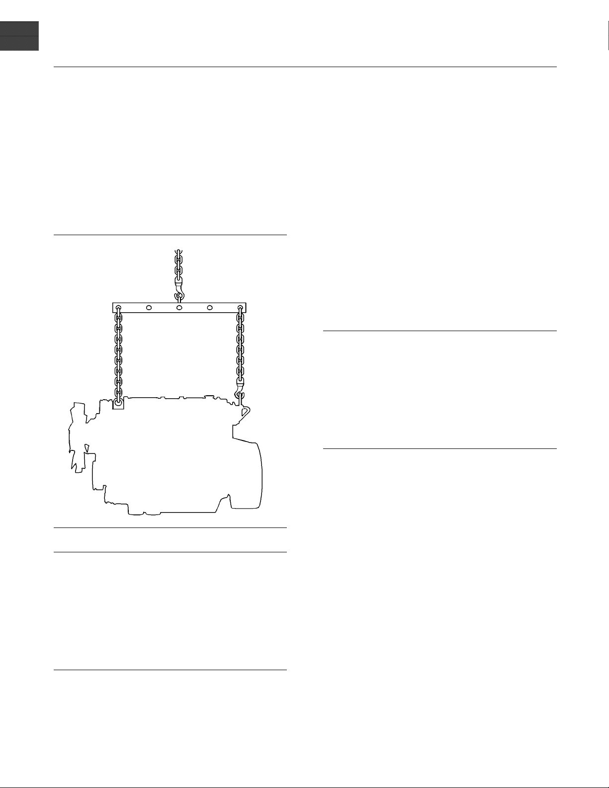
Product Lifting
(Clean Emission Module)
NOTICE
Never bend the eyebolts and the brackets. Only load
the eyeb
ber that the capacity of an eyebolt is less as the angle
between the supporting members and the object becomes l
olts and the brackets under tension. Remem-
ess than 90 degrees.
Illustration 29
NOTICE
er bend the eyebolts and the brackets. Only load
Nev
the eyebolts and the brackets under tension. Remember that the capacity of an eyebolt is less as the angle
ween the supporting members and the object be-
bet
comes less than 90 degrees.
en it is necessary to remove a component at an
Wh
angle, only use a link bracket that is properly rated for
the weight.
Use a hoist to remove heavy components. Use
an adjustable lifting beam to lift the engine. All
upporting members (chains and cables) should be
s
parallel to each other. The chains and cables should
be perpendicular to the top of the object that is being
lifted.
g01097527
When it is necessary to remove a component at an
angle,
the weight.
Use a h
adjustable lifting beam to lift the Clean Emission
Module. All supporting members (chains and cables)
shou
cables should be perpendicular to the top of the
object that is being lifted.
Some removals may require lifting the fixtures in
order to obtain proper balance and safety.
only use a link bracket that is properly rated for
oist to remove heavy components. Use an
ld be parallel to each other. The chains and
Page 31

SEBU8601-01 31
Operation Section
Lifting and Storage
Illustration 30
example
Typical
g02293733
To remove the Clean Emission Module (CEM), use
g eyes (1). Lifting eyes are designed and installed
liftin
for the specific CEM arrangement. Do not use the
lifting eyes for any other purpose than lifting the CEM.
Alterations to the lifting eyes and/or the CEM make
the lifting eyes and the lifting fixtures obsolete. If
ations are made, ensure that proper lifting
alter
devices are provided. Consult your Perkins dealer,
or your Perkins distributor for information regarding
es for proper CEM lifting.
fixtur
Page 32

32 SEBU8601-01
Operation Section
Lifting and Storage
i04161429
Product Lifting
Illustration 31
Typical example
The lifting points (1) are for the application shown. A
suitable lift truck will be required in order to lift the
application.
The lifting eyes on the application will have blanking
devices (2) installed.
Illustration 32
(A) Typical engine lifting eye
(B) Typical CEM lifting eye
g02354678
g02354717
Page 33

SEBU8601-01 33
Operation Section
Lifting and Storage
In order to lift
Operation and Maintenance Manual, “Product Lifting
(Clean Emission Module)”. In order to lift the engine,
refer to this O
“Product Lifting (Engine)”.
the clean emission module, refer to this
peration and Maintenance Manual,
i04084189
Product Storage
(Engine and Aftertreatment)
Perkins are not responsible for damage which may
occur when an engine is in storage after a period in
service.
Your Perkins dealer or your Perkins distributor can
assist in preparing the engine for extended storage
periods.
Condition for Storage
Theenginemustbestoredinawaterproofbuilding.
The building must be kept at a constant temperature.
Engines that are filled with Perkins ELC will have
coolant protection to an ambient temperature of
−36° C (−32.8° F). The engine must not be subjected
to extreme variations in temperature and humidity.
3. The engine oil w
order to store the engine. Provided the correct
specification of engine oil is used the engine
canbestoredf
correct specification of engine oil refer to this
Operation and Maintenance Manual, “Fluid
recommendat
4. Remove the drive belt from the engine.
Sealed Coolant System
Ensure that
ELC, or an antifreeze that meets “ASTM D6210”
specification.
Open Cooling System
Ensure tha
opened. Allow the coolant to drain. Install the drain
plugs. Place a vapor phase inhibitor into the system.
The coola
phase inhibitor has been introduced. The effect of the
vapor phase inhibitor will be lost if the cooling system
is open to
For maintenance procedures ref to this Operation
and Main
the cooling system is filled with Perkins
t all cooling drain plugs have been
nt system must be sealed once the vapor
the atmosphere.
tenance Manual.
ill not need to be drained in
or up to 6 months. For the
ions”.
Aftertreatment
Storage Period
An engine can be stored for up to 6 months provided
all the recommendation are adhered to.
Storage Procedure
Keep a record of the procedure that has been
completed on the engine.
Note: Do not store an engine that has biodiesel in
the fuel system.
1. Ensure that the engine is clean and dry.
a. If the engine has been operated using biodiesel,
the system must be drained and new filters
installed. The fuel tank will require flushing.
b. Fill the fuel system with an ultra low sulfur fuel.
For more information on acceptable fuels refer
to this Operation and Maintenance Manual,
“Fluid recommendations”. Operate the engine
for 15 minutes in order to remove all biodiesel
from the system.
No special procedures are required. The exhaust
outlet of the aftertreatment should be capped. Before
g, the engine and the aftertreatment must be
storin
enclosedinacover.
Month
The crankshaft must be rotated in order to change
the sp
the crankshaft more than 180 degrees. Visibly
check for damage or corrosion to the engine and
afte
Ensure that the engine and aftertreatment are
cove
procedure in the record for the engine.
ly Checks
ring loading on the valve train. Rotate
rtreatment.
red completely before storage. Log the
2. Drain any water from the primary filter water
separator. Ensure that the fuel tank is full.
Page 34

34 SEBU8601-01
Operation Section
Gauges and Indicators
Gauges and Ind icators
i03979889
Gauges and Indicators
Your engine
the gauges that are described. For more information
about the gauge package, see the OEM information.
Gauges provide indications of engine performance.
Ensure that the gauges are in good working order.
Determine
the gauges over a period.
Noticeab
potential gauge or engine problems. Problems may
also be indicated by gauge readings that change
even if t
Determine and correct the cause of any significant
change in the readings. Consult your Perkins
distrib
Some engine applications are equipped with Indicator
Lamps.
aid. There are two lamps. One lamp has an orange
lens and the other lamp has a red lens.
These indicator lamps can be used in two ways:
The in
•
current operational status of the engine. The
indicator lamps can also indicate that the engine
has a f
via the ignition switch.
The i
•
diagnostic codes. This system is activated by
pressing the Flash Code button.
Refer to the Troubleshooting Guide, “Indicator
Lamps” for further information.
If no oil pressure is indicated, STOP the engine. If
maximum coolant temperature is exceeded, STOP
the engine. Engine damage can result.
may not have the same gauges or all of
the normal operating range by observing
le changes in gauge readings indicate
he readings are within specifications.
utor for assistance.
Indicator lamps can be used as a diagnostic
dicatorlampscanbeusedtoidentifythe
ault. This system is automatically operated
ndicator lamps can be used to identify active
NOTICE
1. Remove the load
2. Stop the engine.
3. Check and maintain the oil level.
Jacket Water
Typical temperature range is 82° to 94°C
(179.6° to 169.2°F). This temperature range
will vary ac
temperature.
A 100 kPa (14.5 psi) radiator cap must be installed
on the cooli
for the cooling system is 108° C (226.4° F). This
temperature is measured at the outlet for the
water temp
temperature is regulated by the engine sensors
and the engine ECM. This programming cannot be
altered. A
engine coolant temperature is exceeded.
If the eng
reduce the engine load. If high coolant temperatures
are a frequent event, perform the following
procedu
1. Reduce the load and the engine rpm.
2. Determine if the engine must be shut down
immediately or if the engine can be cooled by
reduci
3. Inspect the cooling system for leaks. If necessary,
consul
load, the engine is running at high idle. The engine is
runni
lever is at the full throttle position with maximum
rated load.
To help prevent engine damage, never exceed the
high idle rpm. Overspeeding can result in serious
damage to the engine. Operation at speeds exceeding high idle rpm should be kept to a minimum.
cordingtoengineloadandtheambient
ng system. The maximum temperature
erature regulator. The engine coolant
n engine derate can occur if the maximum
ine is operating above the normal range,
res:
ng the load.
t your Perkins distributor for assistance.
Tachometer – This gauge indicates engine
speed
ismovedtothefullthrottlepositionwithout
ng at the full load rpm when the throttle control
.
Coolant Temperature –
(rpm). When the throttle control lever
NOTICE
Engine Oil Pressure – The oil pressure
should be greatest after a cold engine is
started. The typical engine oil pressure with
SAE10W40is350to450kPa(50to65psi)atrated
rpm.
A lower oil pressure is normal at low idle. If the load
is stable and the gauge reading changes, perform
the following procedure:
Ammeter – This gauge indicates the
amount of charge or discharge in the
battery charging circuit. Operation of the
indicator should be to the “+” side of “0” (zero).
Fuel Level – This gauge indicates the fuel
level in the fuel tank. The fuel level gauge
operates when the “START/ST OP” switch
is in the “on” position.
Page 35

SEBU8601-01 35
Operation Section
Gauges and Indicators
Service Hour Meter – The gauge indicates
total operating hours of the engine.
Indicator Lam
Shutdown lamp
•
Warning lamp
•
Wait to star
•
Low oil pressure lamp
•
For information, refer to this manual, “Monitoring
System (Table for the Indicator Lamps)” for the
sequence o
warning lamp.
The funct
controlled at engine start-up.
The funct
by the engine ECM. If low oil pressure is detected,
the lamp will be illuminated. The reason for the
ation of the low-pressure lamp should be
illumin
investigated immediately.
All lamp
check that the lamps are functioning when the
keyswitch is turned to the ON position. If any of the
lamps s
should be investigated immediately.
tlamp
f operation of the shutdown lamp and the
ion of the wait to start lamp is automatically
ion of the low oil pressure lamp is controlled
s will illuminate for 2 seconds in order to
tay illuminated, the reason for illumination
ps
Aftertreatment Lamps
formation on the aftertreatment lamp, refer to
For in
this Operation and Maintenance Manual, “Diesel
Particulate Filter Regeneration”.
Page 36

36 SEBU8601-01
Operation Section
Features and Controls
Features and Controls
i03552521
Monitoring System
(Engine)
Table 2
Warning
Lamp
ON ON
OFF OFF
ON OFF
ON FLASHING
FLASHING OFF
FLASH
ING
Shutdown
Lamp
ON
Lamp
Status
Lamp check When the engine start switch is turned to the
No faults There are
Active
diagnostic
fault
Active
diagnostic
fault
Derate and
warning
Engine
shutdown
“ON” position both lamps will illuminate for 2
seconds only.
An active diagnostic fault has been detected.
A serious active diagnostic fault has been
detecte
One or more of the engine protection values has
been ex
One or more of the engine protection values has
been e
fault has been detected.
Description of Lamp Status Engine Status
no active diagnostic faults. The engine is running
d and an engine derate has been invoked.
ceeded.
xceeded or a serious active diagnostic
The engine has not been
started.
normally.
Theengineisrunning
normally.
Theengineisrunning
but the engine has been
derated.
Theengineisrunning
but the engine has been
derated.
Theengineisshutdown
or shutdown is imminent.
i03979949
Moni
toring System
(Engine)
If the Shutdown mode has bee n selected and the
warning indicator activates, engine shutdown may
take as little as 20 seconds from the time the warning indicator is activated. Depending on the application, special precautions should be taken to
avoid personal injury. The e ngine can be restarted
following shutdown for emergency maneuvers, if
necessary.
NOTICE
The Engine Monitoring System is not a guarantee
gainst catastrophic failures. Programmed delays
a
and derate schedules are designed to minimize false
alarms and provide time for the operator to stop the
engine.
The following parameters are monitored:
Coolant temperature
•
Intake manifold air temperature
•
Intake manifold air pressure
•
Oil pressure
•
Pressure in the fuel rail
•
Fuel temperature
•
Fuel filter differential pressure
•
Water in fuel
•
Engine speed/timing
•
Atmospheric pressure (Barometric pressure)
•
The Inlet pressure and outlet pressure of the NOx
•
reduction system
The differential pressure w ithin the NOx reduction
•
system
Page 37

SEBU8601-01 37
Operation Section
Features and Controls
Temperature of
•
The amount of soot in the Diesel particulate filter
•
the NOx reduction system
Programmable O ptions and
Systems Operation
If the Warning/Derate/Shutdown mode has been
selected an
bring the engine to a stop whenever possible. Depending on the application, special precautions
should be t
The engine can be programmed to the following
modes:
“Warning”
The “Warning” lamp and the warning signal (orange
lamp) turn “ON” and the warning signal is activated
continu
more of the engine parameters is not within normal
operating range.
d the warning indicator activates,
aken to avoid personal injury.
ously in order to alert the operator that one or
If there is a sig
temperature, there will be a two second delay in
order to verify the condition.
For each of the programmed modes, refer to
Troubleshooting Guide, “Indicator Lamps” for more
information
For more information or assistance for repairs,
consult you
dealer.
nal for low oil pressure or for coolant
on Indicator Lamps.
r Perkins distributor or your Perkins
Instrument panels and Displays
In order to m
instrument panels are available. These instrument
panels can contain the aftertreatment lamps and the
indicator
The regeneration switch can be incorporate within
the panel.
Also available are mini power displays and
performance monitors. These displays and monitors
can show t
information.
The syst
•
onitor the engine a wide verity of
lamps and the gauges for the application.
he operator the following engine
em configuration parameters
“Warning/Derate”
The “Di
signal (red lamp) is activated. After the warning, the
engine power will be derated. The warning lamp will
begin t
The engine will be derated if the engine exceeds
prese
achieved by restricting the amount of fuel that is
available for each injection. The amount of reduction
of fu
has caused the engine derate, typically up to a limit of
50%. This reduction in fuel results in a predetermined
redu
agnostic” lamp turns “ON” and the warning
o flash when the derating occurs.
t operational limits. The engine derate is
el is dependent on the severity of the fault that
ction in engine power.
“Warning/Derate/Shutdown”
The “Diagnostic” lamp turns “ON” and the warning
signal (red lamp) is activated. After the warning,
engine power will be derated. The engine will
the
continue at the rpm of the set derate until a shutdown
of the engine occurs. The engine can be restarted
ter a shutdown for use in an emergency.
af
A shutdown of the engine may occur in as little
20 seconds. The engine can be restarted after
as
ashutdownforuseinanemergency.However,
thecauseoftheinitialshutdownmaystillexist.
he engine may shut down again in as little as 20
T
seconds.
The customer specified p arameters
•
Diagnostic codes
•
Event c
•
Coolant temperature
•
Oil temperature
•
Oil pr
•
Intake temperature
•
Intake pressure
•
Atmo
•
Fuel temperature
•
odes
essure
spheric pressure
Page 38

38 SEBU8601-01
Operation Section
Features and Controls
i03979996
Sensors and Electrical
Components
Sensor Locations
TheIllustrationwithinthesectionshowsthetypical
locations of the sensors for a 1206E-70 Industrial
Engine. Spe
the illustration due to differences in applications.
cific engines may appear different from
Illustration 33
(1) Engine Intake Throttle Valve
(2) Wastegate Regulator
(3) Control Valve for the NOx Reduction
System (NRS)
(4) Temperature Sensor for the NOx
Reduction System
(5) Intake P ressure Sensor for the NOx
Reduction System (NRS)
(6) Differential Pressure Sensor for the NOx
Reduction System (NRS)
(7) Fuel Pres sure Sensor (Fuel Rail
Pressure Sens or)
(8) Intake Manifold A ir Temperature Sensor
(9) Intake M anifold Pressure Sens or
(10) Electronic Control Module (ECM)
(11) Atmos pheric Pressure Sensor
(Barometric Pressure Sensor)
(12) Primary Speed/Timing Sensor
(13) Starting Motor
(14) Oil Pressure Sens or
g02150593
(15) Oil level Switch ( if Equ ipped)
(16) Diagnostic Connector
(17) Fuel Temperature Sensor
(18) Solenoid for the High Pressure Fuel
Pump
(19) Coolant Temperature Sensor
Page 39

SEBU8601-01 39
Operation Section
Features and Controls
Illustration 34
The location of the fuel filters will depend on the application.
(20) Differential Pressure Switch for the
Secondary Fuel Filter
(21) Water in Fuel Switch
(22) Secondary S peed/Timing S ensor
(23) Fuel Priming Pump
(24) Alternator
g02150594
(25) Refrigerant Compressor (if equipped)
Page 40

40 SEBU8601-01
Operation Section
Features and Controls
Illustration 35
(1) Engine Intake Throttle Valve
(2) Wastegate Regulator
(3) Control Valve for the NRS
(4) Temperature Sensor for the NRS
ustration 36
Ill
(10) Electronic Control Module (EC M)
(11) Atmospheric Pressure Sensor
(Barometric Pressure Sensor)
(5) Intake Pressure Sensor for the NRS
(6) Differential Pressure Sensor for the NRS
(7) Fuel Pres sure Sensor (Fuel Rail
Pressure Sens or)
(12) Primary Speed/Timing Sensor
(13) Starting Motor
(14) Oil Pressure Sens or
g02151173
(8) Intake Manifold Air Temperature Sensor
(9) Intake M anifold Pressure Sens or
g02151174
(15) Oil Level Switch (if Equipped)
The oil level switch (15) will only operate with the
application on level ground and the power in the
position. The engine must be at zero RPM. A
ON
coolant level switch can be installed, this switch only
operates at key on, and the application must be on
vel ground.
le
Page 41

SEBU8601-01 41
Operation Section
Features and Controls
Illustration 37
(16) Diagnostic Connector
(17) Fuel Temperature Sensor
stration 38
Illu
(20) Differential Pressure Switch for the
Secondary Fuel Filter
(18) Solenoid for the High Pressure Fuel
Pump
(21) Water in Fuel Switch
(22) Secondary S peed/Timing S ensor
g02151327
(19) Coolant Temperature Sensor
g02151177
(23) Fuel Priming Pump
Programmable Monitoring System
(PMS)
e Programmable Monitoring System determines
Th
the level of action that is taken by the Engine Control
Module (ECM) (10).In response to a condition that
n damage the engine. These conditions are
ca
identified by the ECM from the signals that are
produced from the following sensors.
Coolant Temperature Sensor
•
Intake Manifold Air Temperature Sensor
•
Intake Manifold Pressure Sensor
•
el Pressure Sensor
Fu
•
Engine Oil Pressure Sensor
•
Primary Speed/Timing Sensor
•
econdary Speed/Timing Sensor
S
•
Page 42

42 SEBU8601-01
Operation Section
Features and Controls
Fuel Temperatu
•
Temperature Sensor for the NRS
•
Intake Pressure Sensor for the NRS
•
Differentia
•
Sensors and
re Sensor
l Pressure Sensor for the NRS
i03928178
Electrical
Components
(Aftertreatment)
The follow
engine aftertreatment system. Due to individual
applications, your system may appear different from
the illus
Glossary
•
ARD Aftertreatment Regeneration Device
•
ing view shows typical features of the
trations.
DOC Dies
•
el Oxidation Catalyst
Page 43

SEBU8601-01 43
Operation Section
Features and Controls
Illustration 39
Typical example
(1) Soot sensor connection
(2) Spa rk plug lead
(3) ARD air pressure sensor
(4) DOC pressure sensor
(5) Pressure differential sensor
(6) Relay
(7) Soot sensor connection
(8) DOC Temperature sensor (not shown)
(9) Harness connector
(10) Main fuel valve (If equipped)
(11) Pilot fuel valve
(12) Fuel pressure sensor (if equipped)
(13) Fuel pressure sensor (pilot)
(14) Aftertreatment device ID
(15) Coil for spark plug
(16) ARD air control valve
(17) Location of s park plug
(18) ARD exhaust gas temperature sensor
g02313693
Page 44

44 SEBU8601-01
Operation Section
Features and Controls
i03928179
Engine Shutoffs and Engine
Alarms
Shutoffs
The shutoffs are electrically operated or mechanically
operated. The electrically operated shutoffs are
controlled
Shutoffs are set at critical levels for the following
items:
Operating temperature
•
Operating pressure
•
Operatin
•
Operating rpm
•
The particular shutoff may need to be reset before
the engine will start.
by the ECM.
g level
Intake manifol
manifold air temperature sensor indicates high intake
air temperature.
Intake manifold pressure – The intake manifold
pressure sensor checks the rated pressure in the
engine manif
Fuel rail pressure – The fuel rail pressure sensor
checks for h
rail.
Engine oil p
sensor indicates when oil pressure drops below rated
system pressure, at a set engine speed.
Engine overspeed – If, the engine rpm exceeds the
overspeed setting the alarm will be activated.
Air filter restriction – Theswitchcheckstheair
filter when the engine is operating.
User-defined switch – This switch can shut down
the engine remotely.
Water in fuel switch – This switch checks for water
in the primary fuel filter when the engine is operating.
d air temperature – Th e intake
old.
igh pressure or low pressure in the fuel
ressure – The engine oil pressure
NOTICE
Always determine the cause of the engine shutdown.
Make necessary repairs before attempting to restart
the eng
Be familiar with the following items:
•
•
•
Alar
The alarms are electrically operated. The operations
of t
The alarm is operated by a sensor or by a switch.
Whe
is sent to the ECM. An event code is created by
theECM.TheECMwillsendasignalinorderto
il
Your engine may be equipped with the following
se
Coolant temperature – The coolant temperature
s
temperature.
ine.
Types and locations of shutoff
tions which cause each shutoff to function
Condi
The resetting procedure that is required to restart
ngine
the e
ms
he alarms are controlled by the ECM.
n the sensor or the switch is activated, a signal
luminate the lamp.
nsors or switches:
ensor indicates high jacket water coolant
Fuel temperature – The fuel temperature sensor
monitors the pressurized fuel in the high-pressure
fuel pum
Fuel differential pressure – This switch checks the
pressu
Note: The sensing element of the coolant
tempe
in order to operate.
Engin
to alert the operator when undesirable operating
conditions occur.
When
be taken before the situation becomes an emergency
in order to avoid possible engine damage.
If corrective measures are not taken within a
reasonable time, engine damage could result. The
arm will continue until the condition is corrected.
al
The alarm may need to be reset.
No
oil level switch are indicators. Both switches operate
when the application is on level ground and the
ngine RPM at zero.
e
p.
re across the fuel filter.
rature switch must be submerged in coolant
es may be equipped with alarms in order
NOTICE
an alarm is activated, corrective measures must
te: If installed, the coolant level switch and the
Page 45

SEBU8601-01 45
Operation Section
Features and Controls
Testing
Turning the ke
the indicator lights on the control panel. All the
indicator lights will be illuminated for 2 seconds after
the keyswitch
immediately.
Refer to Trou
information.
yswitch to the ON position will check
is operated. Replace suspect bulbs
bleshooting, KENR9106 for more
i03554501
Overspeed
ECM ______________________Electronic Control Module
•
RPM ___________________ _____ Revolutions Per Minute
•
An oversp
sensors.
The defa
The ECM will cut the power to the electronic unit
injectors, until the rpm drops below 200 rpm of the
overspe
logged into the ECM memory and a warning lamp will
indicate a diagnostic fault code.
eed is detected by the speed/timing
ult setting for an overspeed is 3000 rpm.
ed setting. A diagnostic fault code will be
An overspeed can be set from 2600 rpm to 3000 rpm.
This setting depends on the application.
Page 46

46 SEBU8601-01
Operation Section
Engine Diagnostics
Engine Diagnostics
i02651093
Self-Diagnostics
Perkins electronic engines have the capability to
perform a self-diagnostics test. When the system
detects an active problem, a diagnostic lamp
is activated. Diagnostic codes will be stored in
permanent memory in the Electronic Control Module
(ECM). The diagnostic codes can be retrieved
by using the electronic service tool. Refer to
Troubleshooting , “Electronic Service Tools” for
further information.
Some installations have electronic displays that
provide direct readouts of the engine diagnostic
codes. Refer to the manual that is provided
by the OEM for more information on retrieving
engine diagnostic codes. Alternatively refer to
Troubleshooting , “Indicator Lamps” for further
information.
i04036139
Diagnostic Flash Code
Retrieval
In order to read the diagnostic flash codes through
the diagnostic lamp, cycle the key switch from off to
on twice wit
The codes will be flashing in sequence. For example
if the flash c
flash once, pause, flash three times, pause, and flash
three times.
After the complete code has flashed, a 3 second
pause will take place before the next code will begin
to flash (if
Note: For more information refer to
Troubles
hin 3 seconds.
ode equals 133, the diagnostic lamp will
another code is present).
hootingmanual.
Active codes represent problems that currently exist.
These problems should be investigated first.
Logged codes represent the following items:
Intermittent problems
•
Recorded events
•
Performance history
•
The problems may have been repaired since the
logging of the code. These codes do not indicate that
a repair is needed. The codes are guides or signals
when a situation exists. Codes may be helpful to
troubleshoot problems.
When the problems have been corrected, the
corresponding logged fault codes should be cleared.
i02651107
Diagnostic Lamp
A diagnostic lamp is used to indicate the existence of
active fault. Refer to Troubleshooting , “Indicator
an
Lamps” for more information. A fault diagnostic
code will remain active until the problem is repaired.
he diagnostic code may be retrieved by using the
T
electronic service tool. Refer to Troubleshooting ,
“Electronic Service Tools” for more information.
Page 47

SEBU8601-01 47
Operation Section
Engine Diagnostics
Table 3
CDL Code
N/A No Diagnostic Code Detected N/A 551
1-2 Cylinder #1 Injector data incorrect 651-2
1-5 Cylinder #1 Injector current below normal 651-5
1-6 Cylinder #1 Injector current above normal 651-6
2-2 Cylinder #2 Injector data incorrect 652-2
2-5 Cylinder #2 Injector current below normal 652-5
2-6 Cylinder #2 Injector current above normal 652-6
3-2
3-5
3-6
4-2
4-5
4-6 Cylinder #4 Injector current above normal 654-6
5-2 Cylinder #5 Injector data incorrect 655-2
5-5
5-6 Cylinder #5 Injector current above normal 655-6
6-2 Cylinder #6 Injector data incorrect 656-2
6-5 Cylinder #6 Injector current below normal 656-5
6-6 Cylinder #6 Injector current above normal 656-6
18-5
18-6
41-3
41-4
91-2
91-3 Throttle Position Sensor voltage above normal 91-3
91-4 Throttle Position Sensor voltage below normal 91-4
91-8 Throttle Position Sensor abnormal frequency, pulse width, or period 91-08
100-3 Engine Oil Pressure Sensor voltage above normal 100-3
100-4 Engine Oil Pressure Sensor voltage below normal 100-4
100-21 Engine Oil Pressure Sensor data drifted low 100-21
110-3 Engine Coolant Temperature Sensor voltage above normal 110-3
110-4 Engine Coolant Temperature Sensor voltage below normal 110-4
168-2
168-3
168-4
172-3
172-4 Intake Manifold Air Temperature Sensor voltage below normal 105-4
Cylinder
Cylinder #3 Injector current below normal
Cylinder #3 Injector current above normal
Cylinder #4 Injector data incorrect
Cylinder #4 Injector current below normal
Cylinder #5 Injector current below normal 655-5
Fu
Fuel Control Valve current above normal
8 Volt DC Supply voltage above normal
8 Volt DC Supply voltage below normal
Throttle Position Sensor erratic, intermittent, or incorrect
Electrical System Voltage erratic, intermittent, or incorrect
Electrical System Voltage voltage above normal
Electrical System Voltage voltage Below normal
Intake Manifold Air Temperature Sensor voltage above normal
#3 Injector data incorrect 653-2
el Control Valve current below normal 1076-5
Description
J1939
Code
653-5
653-6
654-2
654-5
1076-6
678-3
678-4
91-2
168-2
168-3
168-4
105-3
Flash
Code
111
112
113
114
115
116
-
-
517
154
157
168
511
133
(continued)
Page 48

48 SEBU8601-01
Operation Section
Engine Diagnostics
(Table 3, contd)
CDL Code Description
174-3
174-4
190-8
247-9
253-2 Personality Module erratic, intermittent, or incorrect 631-2 415
261-11 Engine Timing Offset fault 637-11 143
262-3 5 Volt Sensor DC Power Supply voltage above normal 3509-3
262-4 5 Volt Sensor DC Power Supply voltage below normal 3509-4
268-2 Programmed Parameter Fault erratic, intermittent, or incorrect 630-2 527
274-3
274-4 Atmospheric Pressure Sensor voltage below normal 108-4
274-13 Atmospheric Pressure Sensor calibration required 108-13
274-21 Atmospheric Pressure Sensor data drifted low 108-21
342-8 Secondary Engine Speed Sensor abnormal frequency, pulse width, or period 723-8 142
526-5 Turbo
526-6 Turbo Wastegate Drive current above normal 1188-6
535-3 Exhaust Temperature Sensor voltage above normal 3241-3
535-4 Exhaust Temperature Sensor voltage below normal 3241-4
774-2 Secondary Throttle Position S ensor erratic, intermittent, or incorrect 29-2
774-3 Secondary Throttle Position Sensor voltage above normal 29-3
774-4 Secondary Throttle Position Sensor voltage below normal 29-4
774-8 Secondary Throttle Position Sensor abnormal frequency, pulse width, or period 29-8
993-2 DPF Active Regeneration Inhibited Due to Inhibit Switch 3703-31
1262-2 Engine Throttle Actuator 1 Control Command not responding properly 3464-7
1634-2
1635-2
1639-9
1743-2
1785-3 Intake Manifold Pressure Sensor voltage above normal 3563-3
1785-4 Intake Manifold Pressure Sensor voltage below normal 3563-4
1785-13 Intake Manifold Pressure Sensor calibration required 3563-13
1785-21 Intake Manifold Pressure Sensor data drifted low 3563-21
1797-3 Fuel Rail Pressure Sensor voltage above normal 157-3
1797-4 Fuel Rail Pressure Sensor voltage below normal 157-4
1797-7 Fuel Rail Pressure Sensor not responding properly 157-7
1834-2 Ignition Key Switch loss of signal 158-2 429
2131-3
2131-4
Fuel Temperature Sensor voltage above normal
Fuel Temperature Sensor voltage below normal
Engine Speed Sensor abnormal frequency, pulse width, or period
SAE J1939 Data Link abnormal update rate
Atmospheric Pressure Sensor voltage above normal
Wastegate Drive current below normal
Idle Validation Switch #1 erratic, intermittent or incorrect
Idle Validation Switch #2 erratic, intermittent or incorrect
Machine Security System M odule abnormal update rate
Engine Operation Mode Selector Switch erratic, intermittent, or incorrect
5 Volt Sensor DC Power Supply #2 voltage above normal
5 Volt Sensor DC Power Supply #2 voltage below normal
J1939
Code
174-3
174-4
190-8 141
-
108-3
5
1188-
558-2 245
2970-2
1196-9
2882-2 144
3510-3
3510-4
Flash
Code
165
514
516
152
177
185
155
-
-
246
197
159
528
(continued)
Page 49

SEBU8601-01 49
Operation Section
Engine Diagnostics
(Table 3, contd)
CDL Code Description
2246-6
2417-5
2417-6
2452-3
2452-4 DPF #1 Intake Temperature Sensor voltage below normal 3242-4 224
2458-3 DPF #1 Differential Pressure Sensor : voltage above normal 3251-3 222
2458-4 DPF #1 Differential Pressure Sensor : voltage below normal 3251-4 222
2460-3 ARD Fuel Pressure #1 Sensor voltage above normal 3480-3 219
2460-4 ARD Fuel Pressure #1 Sensor voltage below normal 3480-4 219
2461-5 ARD Fuel Pressure #1 Control current below normal 3479-5
2461-6 ARD Fuel Pressure #1 Control current above normal 3479-6
2465-5
2465-6
2489-5
2489-6
2490-3
2490-4 ARD Air Pressure Control Actuator Position Sensor voltage below normal 3488-4
2498-3 ARD Supply Air Pressure Sensor voltage above normal 3837-3
2498-4 ARD Supply Air Pressure Sensor voltage below normal 3837-4
2498-13 ARD Supply Air Pressure Sensor calibration required 3837-13
2498-21 ARD Supply Air Pressure Sensor data drifted low 3837-21
2526-3 Air Inlet Temperature Sensor voltage above normal 172-3 232
2526-4 Air Inlet Temperature Sensor voltage below normal 172-4 232
3180-5 Aftertreatment #1 Ignition Transformer Secondary current below normal 4265-5
3180-6
3182-5
3182-6
3385-3
3385-4 Engine Exhaust Gas Recirculation Intake Pressure Sensor voltage below normal 3358-4
3385-13 Engine Exhaust Gas Recirculation Intake Pressure Sensor calibration required 3358-13
3385-21 Engine Exhaust Gas Recirculation Intake Pressure Sensor data drifted low 3358-21
3386-3
3386-4 Engine Exhaust Gas Recirculation Intake Pressure Sensor voltage below normal 412-4
Glow Plug Start Aid Relay current above normal
Ether Injection Control Solenoid current below normal
Ether Injection Control Solenoid current above normal
DPF #1 Intake Temperature Sensor voltage above normal
reatment #1 Ignition Transformer Primary current below normal 3484-5
Aftert
Aftertreatment #1 Ignition Transformer Primary current above normal
ARD Air Pressure Control Actuator current below normal
ARD Air Pressure Control Actuator current above normal
ARD Air Pressure Control Actuator Position Sensor voltage above normal
Aftertreatment #1 Ignition Transformer Secondary current above normal
Aftertreatment #1 Fuel Injector #1 Heater current below normal
Aftertreatment #1 Fuel Injector #1 Heater current above normal
Engine Exhaust Gas Recirculation Intake Pressure Sensor voltage above
normal
Engine Exhaust Gas Recirculation Intake Pressure Sensor voltage above
normal
J1939
Code
676-6 199
626-5
626-6
3242-3 224
3484-6
3487-5
3487-6
3488-3
4265-6
5425-5
5425-6
3358-3
412-3
Flash
Code
233
233
216
243
211
212
-
-
-
-
244
215
231
227
(continued)
Page 50

50 SEBU8601-01
Operation Section
Engine Diagnostics
(Table 3, contd)
CDL Code Description
3397-2
3397-3
3397-4
3397-9
3397-12 DPF #1 Soot Loading Sensor failure 4783-12
3397-13 DPF #1 Soot Loading Sensor calibration required 4783-13
3397-19 DPF #1 Soot Loading Sensor data error 4783-19
3397-21 DPF #1 Soot Loading Sensor data drifted low 4783-21
3405-5 Engine Exhaust Gas Recirculation Valve Control current below normal 2791-5
3405-6 Engine Exhaust Gas Recirculation Valve Control current above normal 2791-6
3407-3 Engine Exhaust Gas Recirculation Valve Position Sensor voltage above normal 27-3
3407-4
3427-5
3427-6
3464-3
3464-4
3464-13 DPF #1 Intake Pressure Sensor calibration required 3609-13
3464-21 DPF #1 Intake Pressure Sensor data drifted low 3609-21
3468-2 Aftertreatment #1 Identification Number Module erratic, intermittent, or incorrect 5576-2
3468-8
3468-14
3511-3
3511-4 Engine Exhaust Gas Recirculation Outlet Pressure Sensor voltage below normal 5019-4
3511-13 Engine Exhaust Gas Recirculation Outlet Pressure Sensor calibration required 5019-13
3511-21 Engine Exhaust Gas Recirculation Outlet Pressure Sensor data drifted low 5019-21
3514-5 Engine Throttle Actuator C ontrol Command current below normal 3464-5
3514-6 Engine Throttle Actuator Control Command current above normal 3464-6
3515-3 Engine Throttle Valve Position Sensor voltage above normal 51-3
3515-4
E172-1 High Air Filter Restriction - Warning 107-15 151
E232-1 High Fuel/Water Separator Water Level - Warning 97-17
E360-1 Low Engine Oil Pressure - Warning 100-17
E360-3 Low Engine Oil Pressure - Shutdown 100-01
DPF #1 Soot Loading Sensor : Erratic, Intermittent, or Incorrect
DPF #1 Soot Loading Sensor : Voltage Above Normal
DPF #1 Soot Loading Sensor : Voltage Below Normal
DPF #1 Soot Loading Sensor abnormal update rate
Engine
Aftertreatment Fuel Pump Relay current below normal
Aftertreatment Fuel Pump Relay current above normal
DPF #1 Intake Pressure Sensor voltage above normal
DPF #1 Intake Pressure Sensor voltage below normal
Aftertreatment #1 Identification Number Module abnormal frequency, pulse
wi
Aftertreatment #1 Identification Number Module special instruction
Engine Exhaust Gas Recirculation Outlet Pressure Sensor voltage above
normal
Engine Throttle Valve Position Sensor voltage below normal
Exhaust Gas Recirculation Valve Position Sensor voltage below normal 27-4
dth, or period
Event Codes
J1939
Code
4783-2
4783-3
4783-4
4783-9
5423-5 218
5423-6 218
3609-3
3609-4
5576-8
5576-14
5019-3
51-4
Flash
Code
226
228
229
223
-
-
-
247
-
-
252
-
157
(continued)
Page 51

SEBU8601-01 51
Operation Section
Engine Diagnostics
(Table 3, contd)
CDL Code Description
E361-1
E361-2
E361-3
E362-1
E363-1 High Fuel Supply Temperature - Warning 174-15
E363-2 High Fuel Supply Temperature - Derate 174-16
E396-2 High Fuel Rail Pressure - Warning 157-16
E398-2 Low Fuel Rail Pressure - Warning 157-18
E499-3
E539-1
E539-2 High Intake Manifold Air Temperature - Derate 105-16
E593-2 Aftertreatment Insufficient Temperature to Complete Regeneration - Derate 3711-31 214
E991-3
E992-3
E995-2 High DPF #1 Soot Loading - Derate 3719-16
E995-3 High DPF #1 Soot Loading - Shutdown 3719-0
E997-1 High DPF #1 Ash Loading - Warning 3720-15
E997-2 High DPF #1 Ash Loading - Derate 3720-16
E1008-2 High DPF #1 Intake Temperature - Derate 3242-16 224
E1014-2 Low DPF #1 Intake Temperature - Derate 3242-18 224
E1022-1 Low ARD Fuel Pressure #1 - Warning 3480-17
E1022-2
E1025-2
E1026-2
E1041-2
E1044-2
E1045-2 Low Intake Manifold Pressure - Derate 102-18
E1050-1 High Aftertreatment #1 Fuel Pressure #1 - Warning 3480-15
E1050-2 High Aftertreatment #1 Fuel Pressure #1 - Derate 3480-16
E1070-1 Aftertreatment Fuel Injector #1 not responding - Warning 3556-7
E1092-1 High Engine Exhaust Gas Recirculation Temperature - Warning 412-15 227
E1092-2 High Engine Exhaust Gas Recirculation Temperature - Derate 412-16 227
E1121-2
E1154-2
E1156-1 High DPF #1 Intake Pressure - Warning 3609-15
E1170-2 Low Aftertreatment #1 Secondary Air Pressure - Derate 3837-18
High Engine Coolant Temperature - Warning
High Engine Coolant Temperature - Derate
High Engine Coolant Temperature - Shutdown
Engine Overspeed - Warning
Fuel Rail #1 Pressure Leak - Shutdown
High Intake Manifold Air Temperature - Warning
DPF Active Regeneration Inhibited Due to Permanent System Lockout Shutdown
DPF Ac
Shutdown
L
Aftertreatment #1 Loss of Ignition - Derate
Aftertreatment #1 Loss of Combustion - Derate
ARD Air Pressure Control Actuator Not Responding To Command - Derate
High Intake Manifold Pressure - Derate
Engine Exhaust Gas Recirculation Valve Control Not Responding to Command
- Derate
Low DPF #1 Intake Pressure - Warning
tive Regeneration Inhibited Due to Temporary System Lockout -
ow ARD Fuel Pressure #1 - Derate 3480-18
J1939
Code
110-15
110-16
110-0
190-15 141
1239-0
105-15
3715-31
3714-31
3473-31 244
3474-31
3487-7 211
102-16
2791-7 228
3609-18
Flash
Code
168
165
159
133
-
-
226
-
-
219
-
197
219
-
223
-
(continued)
Page 52

52 SEBU8601-01
Operation Section
Engine Diagnostics
(Table 3, contd)
CDL Code Description
E1264-3
E1305-1
E1319-2
E2143-3
High Pressure Common Rail Fuel Pressure Relief Valve Active - Shutdown
Initial Assembly Aftertreatment #1 Regeneration Required - Warning
Engine Exhaust Gas Recirculation Mass Flow Rate Not Responding - Derate
Low Engine Coolant Level - Shutdown
J1939
Code
5571-0 159
3483-11
2659-7
111-01 169
Flash
Code
-
-
i01902949
Fault Logg
The system provides the capability of Fault Logging.
When the Electronic Control Module (ECM)
generate
be logged in the memory of the ECM. The codes
that have been logged by the ECM can be identified
by the el
have been logged will be cleared when the fault
has been rectified or the fault is no longer active.
The foll
the memory of the ECM without using a factory
password: Overspeed, low engine oil pressure, and
high en
s an active diagnostic code, the code will
ectronic service tool. The active codes that
owing logged faults can not be cleared from
gine coolant temperature.
ing
i03554534
Engine Ope
ration with Active
Diagnostic Codes
If a diagnostic lamp illuminates during normal engine
operatio
is not within the specification. Use electronic service
toolstochecktheactivediagnosticcodes.
Note: If the customer has selected “DERATE” and if
there is a low oil pressure condition, the Electronic
Control
until the problem is corrected. If the oil pressure is
within the normal range, the engine may be operated
at the r
should be performed as soon as possible.
The act
The cause of the problem should be corrected as
soon as possible. If the cause of the active diagnostic
code i
diagnostic code, the diagnostic lamp will turn off.
Opera
engine can be limited as a result of the active
diagnostic code that is generated. Acceleration
rate
Troubleshooting Guide for more information on the
relationship between these active diagnostic codes
and e
n, the system has identified a situation that
Module (ECM) will limit the engine power
ated speed and load. However, maintenance
ive diagnostic code should be investigated.
s repaired and there is only one active
tion of the engine and performance of the
s may be significantly slower. Refer to the
ngine performance.
Page 53

SEBU8601-01 53
Operation Section
Engine Diagnostics
i01902995
Engine O peration with
Intermittent
If a diagnostic lamp illuminates during normal engine
operation and the diagnostic lamp shuts off, an
intermitte
occurred, the fault will be logged into the memory of
the Electronic Control Module (ECM).
In most cases, it is not necessary to stop the engine
because of an intermittent code. However, the
operator s
and the operator should reference the appropriate
information in order to identify the nature of the event.
The operat
have caused the lamp to light.
nt fault may have occurred. If a fault has
hould retrieve the logged fault codes
or should log any observation that could
Diagnostic Codes
Low power
•
Limits of the engine speed
•
Excessive smoke, etc
•
This inf
the situation. The information can also be used for
future reference. For more information on diagnostic
codes,
engine.
ormation can be useful to help troubleshoot
refer to the Troubleshooting Guide for this
i03905586
Configuration Parameters
The engine electronic control module (ECM) has
two types of configuration parameters. The system
configuration parameters and the customer specified
parameters.
The electronic service tool is required in order to alter
the configuration parameters.
System Configuration Parameters
System configuration parameters affect the emissions
of the engine or the power of the engine. System
configuration parameters are programmed at the
factory. Normally, system configuration parameters
would never require changing through the life
of the engine. System configuration parameters
must be reprogrammed if an ECM is replaced.
System configuration parameters do not require
reprogrammed if the ECM software is changed.
Factory passwords are required to change these
parameters.
Page 54

54 SEBU8601-01
Operation Section
Engine Diagnostics
Table 4
System Configuration Parameters
Configuration Parameters Record
Engine Serial Number
Delayed Eng
Factory Installed Aftertreatment #1 Identification Number
DPF #1 Soot Loading Sensing System Configuration Code
Limp Home Engine Speed Ramp Rate
System Operating Voltage Configuration
Rating Number
CAN Communication Protocol Write Security
ine Shutdown
Customer Specified Parameters
Customer specified parameters allow the engine to
be configured to the exact needs of the application.
The electronic service tool is required in order to alter
the customer configuration parameters.
Customer parameters may be changed repeatedly as
operational requirements change.
Table 5
Customer Specified Parameters
Specified Parameters Record
ttle Type Channel 1
Thro
Throttle Type Channel 2
Continuous Position Throttle Configuration 1
Continuous Position Throttle Configuration 2
Multi Position Throttle Switch Configuration
Throttle Arbitration
quipment ID
E
Low Idle Speed
Ether Solenoid Configuration
Engine Idle Shutdown Minimum Ambient Air Temperature
Engine Idle Shutdown Maximum Ambient Air Temperature
Engine Idle Shutdown Enable Status
Engine Idle Shutdown Delay Time
Engine Idle Shutdown Ambient Temperature Override Enable Status
Delayed Engine Shutdown Maximum Time
High Soot Load Aftertreatment Protection Enable Status
Key off regen enable status
Key Off Aftertreatment Regeneration Maximum Time
(continued)
Page 55

SEBU8601-01 55
Operation Section
Engine Diagnostics
(Table 5, contd)
Multiple Engines on J1939
Air Shutoff
ARD Auto Regeneration Enable Status
Throttle Lock Feature Installation Status
PTO Mode
Throttle Lock Engine Set Speed #1
Throttle Lock Engine Set Speed #2
Throttle Lock Increment Speed Ramp Rate
Throttle Lock Decrement Speed Ramp Rate
Throttle Lock Engine Set Speed Increment
Throttle Lock Engine Set Speed Decrement
Monitoring Mode Shutdowns
Monitoring Mode Derates
ome Desired Engine Speed
Limp H
Engine Acceleration Rate
Engine Speed Decelerating Ramp Rate
Intermediate Engine Speed
Fan
Engine Fan Control
ine Fan Type Configuration
Eng
Engine Cooling Fan Pulley Ratio
Engine Cooling Fan Temperature Error Increasing Hysteresis
Engine Cooling Fan Temperature Error Decreasing Hysteresis
Engine Cooling Fan Current Ramp Rate
Engine Cooling Fan Speed
Top Engine Fan Speed
Minimum Desired Engine Cooling Fan Speed
Engine Cooling Fan Solenoid Minimum Current
Engine Cooling Fan Solenoid Maximum Current
Engine cooling Fan solenoid Dither Frequency
Engine Cooling Fan Solenoid Dither Amplitude
Fan Temperatures
Engine Fan Control Charge Air Cooler Outlet Temperature Input
Enable
Engine Cooling Fan Maximum Air Flow Charge Air Cooler Outlet
Temperature
Engine Cooling Fan Minimum Air Flow Charge Air C ooler Outlet
Temperature
Engine Cooling Fan Control Coolant Temperature Input Enable Status
Engine Cooling Fan Maximum Air Flow Coolant Temperature
(continued)
Page 56

56 SEBU8601-01
Operation Section
Engine Diagnostics
(Table 5, contd)
Engine Cooling Fan Minimum Air Flow Coolant Temperature
Engine Cooling Fan Control Transmission Oil Temperature Input
Enable Status
Engine Cooling Fan Maximum Air Flow Transmission Oil Temperature
Engine Cool
Engine Cooling Fan Control Hydraulic Oil Temperature Input Enable
Status
Engine Cooling Fan Maximum Air Flow Hydraulic Oil Temperature
Engine Cooling Fan Minimum Air Flow Hydraulic Oil Temperature
Engine Cooling Fan Control Auxiliary #1 Temperature Input Enable
Status
Engine Cooling Fan Maximum Air Flow Auxiliary #1 Temperature
Engine Cooling Fan Minimum Air Flow Auxiliary #1 Temperature
Engine Cooling Fan Control Auxiliary #2 Temperature Input Enable
Status
Engine Cooling Fan Maximum Air Flow Auxiliary #2 Temperature
Engine Cooling Fan Minimum Air Flow Auxiliary #2 Temperature
Reversing Fan
Engine Fan Reversing Feature
Engine Fan Reverse Operation Early Termination Enable Status
Engine Fan Manual Purge
Engine Fan Suspend Purge
gine Fan Purge Cycle Interval
En
Engine Fan Purge Cycle Duration
Other Parameters
Maintenance Indicator Mode
Maintenance Level 1 Cycle Interval Hours
Coolant Level Sensor
Air Filter Restriction Switch Installation Status
Air Filter Restriction Switch Configuration
Fuel/Water Separator Switch Installation Status
User Defined Switch Installation Status
Auxiliary Temperature Sensor Installation Status
Auxiliary Pressure Sensor Installation Status
Engine Overspeed Setpoint
Fuel Filter Differential Pressure Switch Config
Diesel Particulate Filter Regeneration Force/ Inhibit Switch Installation
Diesel Particulate Filter Regeneration Inhibit Indicator Installation
Diesel Particulate Filter Soot Loading Indicator Installation
High Exhaust System Temperature Indicator Installation
Auxiliary Temp #2
ing Fan Minimum Air Flow Transmission Oil Temperature
(continued)
Page 57

SEBU8601-01 57
Operation Section
Engine Diagnostics
(Table 5, contd)
Remote Torque Speed Control Enable Status
Number of Engine Operating Mode Switches
Engine Operating Mode Configuration
Page 58

58 SEBU8601-01
Operation Section
Engine Starting
Engine Starting
i03648917
Before Starting Engine
Perform the
periodic maintenance before the engine is started.
Inspect the engine compartment. This inspection can
help preve
Operation and Maintenance Manual, “Maintenance
Interval Schedule” for more information.
Ensure that the engine has an adequate fuel
•
supply.
Open the fuel supply valve (if equipped).
•
All valv
supply lines must be open. Damage to the fuel system
can occure if fuel lines are closed with the engine in
operat
If the engine has not been started for several weeks,
fuel may have drained from the fuel system. Air
may have entered the filter housing. Also, when fuel
filters have been changed, some air pockets will be
trapped in the engine. In these instances, prime the
fuel system. Refer to the Operation and Maintenance
Manual, “Fuel System - Prime” for more information
on priming the fuel system. Also, check that the fuel
specification is correct and that the fuel condition
is correct. Refer to the Operation and Maintenance
Manual, “Fuel Recommendations”.
required daily maintenance and other
nt major repairs at a later date. Refer to the
NOTICE
es in the fuel return line must be open and fuel
ion.
i04084389
Starting the Eng ine
Note: Do not ad
start-up. The electronic control module (ECM) will
control the engine speed during start-up.
Starting the Engine
1. Disengage any equipment that is driven by the
engine.
2. Turn the keyswitch to the RUN position. Leave the
keyswitchintheRUNpositionuntilthewarning
light for t
Note: During the key on, the indicator lamps will
be illumi
operation. If any of the lamps do not illuminate,
replace the bulb.
3. When the warning light for the glow plugs is
Note: Th
the glow plugs will change due to the temperature
of the engine.
Do not engage the starting motor when flywheel is
turning. Do not start the engine under load.
If the engine fails to start within 30 seconds, release
the starter switch or button and wait two minutes to
allo
start the engine again.
nated for 2 seconds in order to check lamp
extinguished, turn the keyswitch to the START
positio
motor and crank the engine.
e operating period of the warning light for
w the starting motor to cool before attempting to
justtheenginespeedcontrolduring
he glow plugs is extinguished.
n in order to engage the electric starting
NOTICE
ine exhaust contains products of c ombustion
Eng
which may be harmful to your he alth. Always start
and operate the engine in a well ventilated area
d, if in an enclosed area, vent the exhaust to the
an
outside.
not start the engine or move any of the controls
Do
•
if there is a “DO NOT OPERATE” warning tag or
similar warning tag attached to the start switch or
othecontrols.
t
Reset all of the shutoffs or alarm components.
•
Ensure that any driven equipment has been
•
disengaged. Minimize electrical loads or remove
any electrical loads.
4. Allo
5. Rep
w the keyswitch to return to the RUN position
after the engine starts.
eat step 2 through step 4 if the engine fails
to start.
i03570564
Cold Weather Starting
Do not use aerosol types of starting aids such as
ether. Such use could result i n an explosion and
personal injury.
Page 59

SEBU8601-01 59
Operation Section
Engine Starting
Startability w
−18 °C (0 °F) from the use of a jacket water heater
or extra battery capacity.
When Group 2 diesel fuel is used, the following items
provide a means of minimizing starting problems
and fuel prob
heaters, jacket water heaters, fuel heaters, and fuel
line insulation.
Use the procedure that follows for cold weather
starting.
Note: Do not adjust the engine speed control during
start-up. The electronic control module (ECM) will
control th
1. Disengage any driven equipment.
2. Turn the keyswitch to the RUN position. Leave the
keyswitch in the RUN position until the warning
light for
Do not engage the starting motor when flywheel is
turning
If the engine fails to start within 30 seconds, release
the star
allow the starting motor to cool before attempting to
start the engine again.
illbeimprovedattemperaturesbelow
lems in cold weather: Engine oil pan
e engine speed during start-up.
the glow plugs is extinguished.
NOTICE
. Do not start the engine under load.
ter switch or button and wait two minutes to
7. Operate the eng
reach operating temperature. Check the gauges
during the warm-up period.
ine at low load until all systems
i03663103
Starting with Jump Start
Cables
Improper jump start cable connections can cause
an explosi
Prevent sparks near the batteries. Sparks could
cause vap
cable ends to contact each other or the engine.
Note: If
the starting failure. Refer to Troubleshooting, “Engine
Will Not Crank and Engine Cranks But Will Not Start”
for furt
If the engine will not start only due to the condition
of the battery, either charge the battery, or start the
engine
cables.
The condition of the battery can be rechecked after
the eng
on resulting in personal injury.
ors to explode. Do not allow jump start
it is possible, first diagnose the reason for
her information. Make any necessary repairs.
by using another battery with jump start
inehasbeenswitchedOFF.
3. When the warning light for the glow plugs is
extinguished turn the keyswitch to the START
ion in order to engage the electric starting
posit
motor and crank the engine.
: The operating period of the warning light for
Note
the glow plugs will change due to the temperature
of the engine.
4. Allow the keyswitch to return to the RUN position
after the engine starts.
5. Repeat step 2 through step 4 if the engine fails
to start.
Note: The engine should not be “raced” in order to
speed up the warm up process.
6. Allow the engine to idle for three to five minutes, or
allow the engine to idle until the water temperature
dicator begins to rise. When idling after the
in
engine has started in cold weather, increase the
engine rpm from 1000 to 1200 rpm. This will
rm up the engine more quickly. Maintaining
wa
an elevated low idle speed for extended periods
will be easier with the installation of a hand
hrottle. Allow the white smoke to disperse before
t
proceeding with normal operation.
NOTICE
Using a battery source with the same voltage as the
electric starting motor. Use ONLY equal voltage for
jump starting. The use of higher voltage will damage
the electrical system.
Do not reverse the battery cables. The alternator can
be damaged. Attach ground cable last and remove
first.
Turn all electrical accessories OFF before attaching
the jump start cables.
Ensure that the main power switch is in the OFF position before attaching the jump start cables to the engine being started.
1. Turn the start switch on the stalled engine to the
OFF position. Turn off all the engine's accessories.
2. Connect one positive end of the jump start cable
to the positive cable terminal of the discharged
battery. Connect the other positive end of the jump
start cable to the positive cable terminal of the
electrical source.
Page 60

60 SEBU8601-01
Operation Section
Engine Starting
3. Connect one neg
to the negative cable terminal of the electrical
source. Connect the other negative end of the
jump start cab
chassis ground. This procedure helps to prevent
potential sparks from igniting the combustible
gases that ar
Note: The engine ECM must be powered before the
starting mo
4. Start the engine in the normal operating procedure.
Refer to thi
“Starting the Engine”.
5. Immediate
the jump start cables in reverse order.
After jump
fully recharge batteries that are severely discharged.
The batteries must be replaced or charged to the
proper vo
is stopped. Many batteries which are considered
unusable are still rechargeable. Refer to Operation
and Maint
Testing and Adjusting Manual, “Battery - Test”.
tor is operated or damage can occur.
ly after the engine is started, disconnect
starting, the alternator may not be able to
ltage with a battery charger after the engine
enance Manual, “Battery - Replace” and
ative end of the jump start cable
le to the engine block or to the
e produced by some batteries.
s Operation and Maintenance Manual,
i02330138
After Starting Engine
Note: In ambie
(32 to 140°F), the warm-up time is approximately
three minutes. In temperatures below 0°C (32°F),
additional w
When the engine idles during warm-up, observe the
following c
Do not check the high pressure fuel lines with the
engine or t
inspect the engine in operation, always use the
proper inspection procedure in order to avoid a
fluid penet
Maintenance Manual, “General hazard Information”.
Check for
•
and at one-half full rpm (no load on the engine)
before operating the engine under load. This is not
possible
Allow the engine to idle for three to five minutes, or
•
allow th
indicator begins to rise. Check all gauges during
the warm-up period.
nt temperatures from 0 to 60°C
arm-up time may be required.
onditions:
he starting motor in operation. If you
ration hazard. Refer to Operation and
any fluid or for any air leaks at idle rpm
in some applications.
e engine to idle until the water temperature
Note: Gauge readings should be observed and
the data should be recorded frequently while the
engine
will help to determine normal readings for each
gauge. Comparing data over time will also help
detec
changes in the readings should be investigated.
is operating. Comparing the data over time
t abnormal operating developments. Significant
Page 61

SEBU8601-01 61
Operation Section
Engine Operation
Engine Operation
i04156659
Engine Operation
Proper oper
in obtaining the maximum life and economy of
the engine. If the directions in the Operation and
Maintenan
minimized and engine service life can be maximized.
Thetimeth
normal operating temperature can be less than the
time taken for a walk-around inspection of the engine.
The engine can be operated at the rated rpm after
the engine is started and after the engine reaches
operati
operating temperature sooner during a low engine
speed (rpm) and during a low-power demand. This
procedu
at no load. The engine should reach operating
temperature in a few minutes.
Avoid excess idling. Excessive idling causes carbon
buildup, engine slobber, and soot loading of the
Diesel
engine.
Gauge
should be recorded frequently while the engine
is operating. Comparing the data over time will
help t
Comparing data over time will also help detect
abnormal operating developments. Significant
ges in the readings should be investigated.
chan
Redu
The Diesel Particulate Filter (DPF) and the
ertreatment Regeneration Device (ARD) work
Aft
together in order to reduce particulate emissions. The
DPF collects the soot and any ash that is produced by
combustion in the engine. During regeneration,
the
the soot is converted into a gas which is released into
the atmosphere. The Ash remains in the DPF until
e ash is cleaned out of the DPF.
th
The temperature of the DPF must be above a
rticular value in order for regeneration to occur.
pa
The exhaust gas provides heat for the regeneration
process. There are two types of regeneration:
Passive Regeneration – Is a chemical reaction
within the system and the engine provides sufficient
xhaust gas temperature for regeneration.
e
ation and maintenance are key factors
ce Manual are followed, costs can be
at is needed for the engine to reach
ng temperature. The engine will reach normal
re is more effective than idling the engine
Particulate Filter (DPF). This is harmful to the
readings should be observed and the data
o determine normal readings for each gauge.
ction of Particulate Emissions
Active Regener
does not provide sufficient exhaust temperature for
passive regeneration. The ARD operates in order to
raise the temp
regeneration process is complete, the ARD turns off.
The operator
the ARD from dash lamps and the driver will be able
to request a regeneration by using a switch. Refer to
this Operat
System” for more information.
ation – The engines duty cycle
erature of the exhaust gas. When the
will receive information on the status of
ion and Maintenance Manual, “Monitoring
Engine Operation and A ctive
Regenerati
Your ARD may perform an active regeneration while
your engin
of the DPF, the engine may operate at idle for periods
longer than 5 minutes.
on
e is at idle. During this active regeneration
i04084269
Diesel Particulate Filter
Regeneration
The temperature of the exhaust gas and the
temperature of the exhaust system components can reach up to 650 °C (1202 °F) during
regeneration. An unexpected failure of the engine
or an unexpected failure of the aftertreatment
system may increase temperature at the diesel
particulate filter to as high as 900 °C (1652 °F)
gas temperature. This may result in fire, burn, or
explosion hazards, which may result in personal
injury or death. Do not expose flammable material
or explosive atmospheres to exhaust gas or to
exhaust system components during regeneration.
Regeneration
Regeneration is the removal of soot from the
Diesel Particulate Filter (DPF). The Aftertreatment
Regeneration Device (ARD) is used to regenerate
the DPF. The DPF traps both soot and ash. The
ash is removed through a manual cleaning process.
Refer to Operation and Maintenance Manual, “Diesel
Particulate Filter - Clean” for more information on the
service of the DPF.
Types of Regeneration
Passive Regeneration – Is a chemical reaction
within the system and the engine will create enough
heat in order to regenerate the DPF.
Page 62

62 SEBU8601-01
Operation Section
Engine Operation
Active Regener
enough heat in order to regenerate the DPF. The
ARD must be used to create the heat necessary to
regenerate th
ation – The engine does not create
eDPF.
Lamps
Five dash lamps can be affected by the DPF
regeneratio
alter the operator.
temperatur
operate at level 2.
Note: In some situations, the DPF lamp may stay
illumina
illuminated DPF lamp indicates that a complete
regeneration has not been performed. A complete
regener
0%. If the DPF lamp stays illuminated, perform a
regeneration without interruption until the soot level
is reduc
the DPF lamp.
lamp w
lamp will flash if regeneration is not activated. Also,
the DPF lamp will be illuminated.
Note:
as a diagnostic lamp. For more information refer to
this Operation and Maintenance Manual, “Diagnostic
Lamp
and may shut down. Also, the DPF lamp will be
uminated.
ill
n. Also, the horn can be used in order to
High Exhaus
Lamp (HEST) – The lamp is illuminated
when the ARD is activated and the exhaust
e is greater than 450 °C (842 °F).
DPF Lamp – This lamp provides a general
indication of the soot load. The lamp is off
when the so
ted when the soot load is below 90%. The
ation is when the soot level is reduced to
ed to 0%. A complete regeneration will reset
Amber o
lamp indicates that the soot load has
increased. Regeneration is required. This
ill be illuminated at level 3 soot load and the
Amber or yellow Warning Lamp can be use
”.
Red Stop Lamp – This lamp indicates that
oot load is extremely high. The soot
the s
load is at level 3. The engine will derate
t System Temperature
ot load is normal. The lamp will
r yellow Warning Lamp – This
Forced regener
•
Low speed automatic regeneration and enhanced
automatic reg
ECM. During this regeneration the operator will see
the high exhaust system temperature lamp (HEST)
illuminated
Low speed automatic – Low speed automatic
regenerati
automatically with the engine speed in a low idle
condition or near low idle condition. In order for a low
speed autom
conditions must be met:
Soot level
•
the soot level monitor (if equipped).
Engine spe
•
The interlocks for the application will raise the
•
RPM to the
regeneration to occur. The engine RPM will be
from1000to1400RPM.
Refer to the OEM for the applications interlocks
•
required to be engaged before regeneration can
take pla
Enhanced automatic regeneration – This mode
of DPF re
place at higher engine rpm and higher engine loads.
In order for enhanced automatic regenerations to
occur,
Soot level must be between level 2 and level 3 on
•
the so
Engine speed must be greater than 1400 rpm.
•
Minimum engine idle speed input must be set.
•
Setting the input will not allow engine speed to
fall
regeneration. If minimum low idle speed input is
not available, regeneration will stop if engine speed
drop
Refer to the OEM for the applications interlocks
•
req
take place.
.
on allows for the DPF regeneration to start
ce.
generation allows for regeneration to take
the following conditions must be met:
ot level monitor (if equipped).
below 1000 rpm during enhanced automatic
s below 1000 rpm.
uired to be engaged before regeneration can
ation
eneration are controlled by the engine
atic regeneration to occur, the following
must be between level 1 and level 3 on
ed must be below 1400 rpm.
required engine speed in order for the
DPF Disable Lamp – This lamp is
illuminated whenever the ARD disable
tch is activated or the system has been
swi
disabled by the engine ECM.
des of Regeneration
Mo
Low speed automatic
•
Enhanced automatic regeneration
•
ced regeneration – A forced regeneration is
For
initiated by pressing the regeneration switch. A forced
regeneration is allowed during normal operation up
level 3. A forced regeneration can be performed
to
in the low speed automatic window or the enhanced
automatic regeneration window.
Page 63

SEBU8601-01 63
Operation Section
Engine Operation
Regeneration Switch
Note: The MIDDLE position of the regeneration
switch is the default position for automatic modes
of regeneration.
Note: Some OEMs may use other means of
activating a forced regeneration such as touch screen
interfaces.
Force Regeneration – Press in the top
of the switch for 2 seconds in order to
begin regeneration. An indicator light on
the switch will become active showing that the
regeneration is active. The HEST lamp will become
active showing that the regeneration is active. The
high exhaust temperature indicator will deactivate
after regeneration is completed or the regeneration
has been disabled.
Disable Regeneration – Press in the
bottom of the switch for 2 seconds in order
to disable regeneration. An indicator light on
the switch will become active. The disable indicator
lamp will illuminate. The indicator will deactivate after
the disable regeneration is completed.
Note: To re-enable the regeneration, cycle the engine
start switch key or press and hold down the force
regeneration switch for 2 seconds.
Note: If the engine start switch key is cycled while
the regeneration system is disabled via the disable
regeneration switch, press and hold the disable
regeneration switch for 2 seconds to reinitiate the
disable regeneration.
Soot Level Monitoring and Indicator
Lamps
During the normal working cycle of the engine the
ECM will control when the regeneration will occur.
Operation of the engine is not recommended with
theamberwarninglightflashing, or the red lamp
illuminated. Operation of the engine at this level
could damage the DPF.
Page 64

64 SEBU8601-01
Operation Section
Engine Operation
Table 6
Lamp Operation Action Require
HEST Lamp On The ARD is activated and the exhaust
DPF Lamp On The lamp provides a general indication
Amber Warning
Lamp
Amber Warning
Lamp
RedStopLamp On
On
Lamp is now
flashing
temperature is greater than 450 °C
(842 °F)
of the soot load. The lamp is off when
thesootloadisnormal.Thelampwill
operate at level 2 and above.
The lamp indicates that the soot load has
increased. Regeneration is required.
The flashing lamp will indicate that the
engine has continued to be operated,
regeneration is required.
The engine could be derated or the
engine could be shut down.
None
A regeneration is required. In automatic
mode the ECM will decide when to allow
the regeneration.
If the DPF lamp stays illuminated allow
a regeneration without interruption. An
uninterrupted regeneration will reset the
DPF lamp.
A regeneration is required. Perform a
forced regeneration, or allow the ECM
control.
An urgent regeneration is required. If
a regeneration is not allowed, the DPF
couldbedamage.
Oncetheengineentresintoshutdown
mode you must contact your Perkins
dealer or your Perkins distributor. Yo u r
dealer or distributor will need to perform a
service level regeneration. The DFP may
need to be replaced.
d
Some applications will be equipped with a monitoring
gauge. Illustration 40 is an example of the levels of
soot loading on a gauge.
Illustration 40
(1) Norm al operation level 1
(2) Level 2 with DPF lamp illuminated
(3) level 3 with DP F lamp illuminated and amber warning lamp
illuminated.
g02153650
During the normal working cycle of the engine the
ECM will control when the regeneration will occur.
Regeneration will take place by low speed automatic
regeneration or by enhanced automatic regeneration.
Operation of the engine at level 3 and not allowing a
regeneration to be performed could damage the DFP.
Soot Level and Engine Loading
ustration 41
Ill
(A) E ngine load factor
(B) E ngine RPM
(1) Low speed automatic regeneration
(2) High s peed automatic regeneration (60-80% soot load)
(3) High s peed automatic regeneration (80-100% soot load)
g02237313
In some circumstances high speed regeneration
cannot occur. Allow the application to operate at
ower load factor in order to allow low speed
al
regeneration to occur.
Illustration 41 is a guide to show engine RPM engine
load and when regeneration can occur.
Page 65

SEBU8601-01 65
Operation Section
Engine Operation
i04018232
Fuel Conservation Practices
The efficiency
economy. Perkins design and technology in
manufacturing provides maximum fuel efficiency in
all applicat
in order to attain optimum performance for the life
of the engine.
Avoid spilling fuel.
•
Fuel expan
may overflow from the fuel tank. Inspect fuel lines for
leaks. Repair the fuel lines, as needed.
Be aware of the properties of the different fuels.
•
Use only the recommended fuels. Refer to the
Operatio
Recommendations”for further information.
Avoid unn
•
Shut off the engine rather than idle for long periods of
time.
Observe the service indicator frequently. Keep the
•
air clea
Ensure that the turbocharger is operating correctly.
•
For mor
Maintenance Manual , “Turbocharger - Inspect”
of the engine can affect the fuel
ions. Follow the recommended procedures
ds when the fuel is warmed up. The fuel
ns and Maintenance Manual, “Fuel
ecessary idling.
ner elements clean.
e information refer to this Operation and
ain a good electrical system.
Maint
•
One faulty battery cell will overwork the alternator.
ault will consume excess power and excess
This f
fuel.
elt should be in good condition. Refer to the
The b
•
Systems Operation, Testing and Adjusting, “V-Belt
Test” for further information.
Ensure that all of the connections of the hoses are
•
tight. The connections should not leak.
Ensure that the driven equipment is in good
•
working order.
Cold engines consume excess fuel. Utilize heat
•
from the jacket water system and the exhaust
stem, when possible. Keep cooling system
sy
components clean and keep cooling system
components in good repair. Never operate the
gine without water temperature regulators.
en
All of these items will help maintain operating
temperatures.
Page 66

66 SEBU8601-01
Operation Section
Engine Stopping
Engine Stopping
i02334873
Stopping the Engine
NOTICE
Stopping the engine immediately after it has been
working under load, can result in overheating and accelerated wear of the engine components.
Avoid accelerating the engine prior to shutting it down.
Avoiding hot engine shutdowns will maximize turbocharger shaft and bearing life.
Note: Individual applications will have different
control systems. Ensure that the shutoff procedures
are understood. Use the following general guidelines
in order to stop the engine.
1. Remove the load from the engine. Reduce the
engine speed (rpm) to low idle. Allow the engine
to idle for five minutes in order to cool the engine.
2. Stop the engine after the cool down period
according to the shutoff system on the engine and
turn the ignition key switch to the OFF position.
If necessary, refer to the instructions that are
provided by the OEM.
i01903586
Emer
gency S topping
i03648931
After Stopping Engine
Note: Before y
the engine for at least 10 minutes in order to allow
the engine oil to return to the oil pan.
Contact wit
penetration and burn hazards. High pressure fuel spray may cause a fire hazard. Failure to follow these i
structions may cause personal injury or death.
After the
•
10 minutes in order to allow the fuel pressure to
be purged from the high pressure fuel lines before
any servi
fuel lines. If necessary, perform minor adjustments.
Repair any leaks from the low pressure fuel
system a
systems. Replace any high pressure fuel line that
has leaked. Refer to Disassembly and assembly
Manual,
Check the crankcase oil level. Maintain the oil level
•
betwee
the engine oil level gauge.
If the e
•
note the reading. Perform the maintenance that
is in the Operation and Maintenance Manual,
tenance Interval Schedule”.
“Main
ou check the engine oil, do not operate
h high pressure fuel may cause fl uid
nspection, maintenance and service in-
engine has stopped, you must wait for
ce or repair is performed on the engine
nd from the cooling, lubrication or air
“Fuel Injection Lines - Install”.
n the “MIN” mark and the “MAX” mark on
ngine is equipped with a service hour meter,
NOTICE
Emergency shutoff controls are for EMERGENCY use
ONLY. DO NOT use emergency shutoff devices or
controls for normal stopping procedure.
The OEM may have equipped the application with
an emergency stop button. For more information
about the emergency stop button, refer to the OEM
information.
Ensure that any components for the external system
that support the engine operation are secured after
the engine is stopped.
Fill the fuel tank in order to help prevent
•
Only use antifreeze/coolant mixtures recommended in
the
is in this Operation and Maintenance Manual. Failure
to do so can cause engine damage.
Pressurized System: Hot coolant can cause serious burns. To open the cooling system filler cap,
stop the engine and wait until the cooling system
components are cool. Loosen the cooling system
pressure cap slowly in order to relieve the pressure.
•
mulation of moisture in the fuel. Do not overfill
accu
the fuel tank.
NOTICE
Refill Capacities and Recommendations topic that
Allow the engine to cool. Check the coolant level.
Page 67

SEBU8601-01 67
Operation Section
Engine Stopping
Check the coola
•
and the correct corrosion protection. Add the
correct coolant/water mixture, if necessary.
Perform all required periodic maintenance on all
•
driven equipment. This maintenance is outlined in
the instruct
nt for correct antifreeze protection
ions from the OEM.
Page 68

68 SEBU8601-01
Operation Section
Cold Weather Operation
Cold Weather Operation
i04156731
Cold Weather Operation
Perkins Diesel Engines can operate effectively in
cold weather. During cold weather, the starting and
the operation of the diesel engine is dependent on
the following items:
The type of fuel that is used
•
The viscosity of the engine oil
•
The operation of the glow plugs
•
Optional Cold starting aid
•
Battery condition
•
This section will cover the following information:
Potential problems that are caused by cold-weather
•
operation
Suggest steps which can be taken in order to
•
minimize starting problems and operating problems
when the ambient air temperature is between
0° to−40 °C (32° to 40 °F).
Install the cor
•
before the beginning of cold weather.
Check all rubb
•
weekly.
Check all ele
•
fraying or damaged insulation.
Keep all bat
•
Fill the fuel tank at the end of each shift.
•
Check the air cleaners and the air intake daily.
•
Check the air intake more often when you operate
in snow.
Ensure that the glow plugs are in working order.
•
Refer to Tr
Tes t” .
Personal injury or property damage can result
from alcohol or starting fluids.
Alcohol or starting fluids are highly flammable and
toxic and if improperly stored could result in injury
or prope
rect specification of engine lubricant
er parts (hoses, fan drive belts,)
ctrical wiring and connections for any
teries fully charged and warm.
oubleshooting, “Glow Plug Starting Aid-
rty damage.
The operation and maintenance of an engine in
freezing temperatures is complex . This complexity is
because of the following conditions:
Weather conditions
•
Engine applications
•
Recommendations from your Perkins dealer or
your Perkins distributor are based on past proven
practices. The information that is contained in
this section provides guidelines for cold-weather
operation.
Hints for Cold Weather Operation
If the engine will start, operate the engine until a
•
minimum operating temperature of 80° C (176° F)
is achieved. Achieving operating temperature will
help prevent the intake valves and exhaust valves
from sticking.
The cooling system and the lubrication system
•
for the engine do not lose heat immediately upon
shutdown. This means that an engine can be shut
down for a period and the engine can still have the
ability to start readily.
Do not use aerosol types of starting aids such as
ether. Such use could result i n an explosion and
personal injury.
Forjumpstartingwithcablesincoldweather,
•
refer to the Operation and Maintenance Manual,
“Starting with Jump Start Cables.” for instructions.
Viscosity of the Engine Lubrication
Oil
Correct engine oil viscosity is essential. Oil viscosity
affects the amount of torque that is needed to
crank the engine. Refer to this Operation and
Maintenance Manual, “Fluid Recommendations” for
the recommended viscosity of oil.
Recommendations for the Coolant
Provide cooling system protection for the lowest
expected outside temperature. Refer to this Operation
and Maintenance Manual, “Fluid Recommendations”
for the recommended coolant mixture.
Page 69

SEBU8601-01 69
Operation Section
Cold Weather Operation
In cold weather
correct glycol concentration in order to ensure
adequate freeze protection.
, check the coolant often for the
Engine Block Heaters
Engine block
engine jacket water that surrounds the combustion
chambers. This heat provides the following functions:
Startability is improved.
•
Warm up time
•
An electric block heater can be activated once the
engine is s
240 V dc. The output can be 750/1000W. Consult
your Perkins dealer or your Perkins distributor for
more infor
Idling th
When idling after the engine is started in cold
weather,
rpm. This idling will warm up the engine more quickly.
Maintaining an elevated low idle speed for extended
periods
throttle. The engine should not be “raced” in order to
speed up the warm-up process.
While the engine is idling, the application of a light
load (parasitic load) will assist in achieving the
minimu
operating temperature is 80° C (176° F).
heaters (if equipped) heat the
is reduced.
topped. A block heater can be 110 V dc or
mation.
e Engine
increase the engine rpm from 1000 to 1200
will be easier with the installation of a hand
m operating temperature. The minimum
When starting a
times without being operated in order to warm up
completely, the carbon deposits become thicker.
This starting
problems:
Free operati
•
Valves become stuck.
•
Pushrods may become bent.
•
Other damag
•
result.
For this re
the engine must be operated until the coolant
temperature is 80° C (176° F) minimum. Carbon
deposits o
and the free operation of the valves and the valve
components will be maintained.
The engine must be thoroughly warmed in order
to keep other engine parts in better condition. The
service l
Lubrication will be improved. There will be less acid
and less sludge in the oil. This condition will provide
longer s
rings, and other parts. However, limit unnecessary
idle time to10 minutes in order to reduce wear and
unneces
ife of the engine will be generally extended.
ervice life for the engine bearings, the piston
sary fuel consumption.
nd stopping an engine many
and stopping can cause the following
on of the valves is prevented.
e to valve train components can
ason, when the engine is started,
n the valve stems will be kept at a minimum
The Water Temperature Regulator and
Insula
ted Heater Lines
Recommendations for Cool ant
Warm U
Warm up an engine that has cooled below normal
opera
-up should be performed before the engine is
returned to full operation. During operation in very
temperature conditions, damage to engine
cold
valve mechanisms can result from engine operation
for short intervals. This damage can happen if the
ne is started and the engine is stopped many
engi
times without being operated in order to warm up
completely.
When the engine is operated below normal operating
temperatures, fuel and oil are not completely burned
he combustion chamber. This fuel and oil causes
in t
soft carbon deposits to form on the valve stems.
Generally, the deposits do not cause problems and
e deposits are burned off during operation at
th
normal engine operating temperatures.
p
ting temperatures due to inactivity. This warn
The engine is equipped with a water temperature
ator. When the engine coolant is below the
regul
correct operating temperature, jacket water circulates
through the engine cylinder block and into the
e cylinder head. The coolant then returns to the
engin
cylinder block via an internal passage that bypasses
the valve of the coolant temperature regulator. This
res that coolant flows around the engine under
ensu
cold operating conditions. The water temperature
regulator begins to open when the engine jacket
r has reached the correct minimum operating
wate
temperature. As the jacket water coolant temperature
rises above the minimum operating temperature, the
er temperature regulator opens further allowing
wat
more coolant through the radiator to dissipate excess
heat.
The progressive opening of the water temperature
regulator operates the progressive closing of the
pass passage between the cylinder block and
by
head. This action ensures maximum coolant flow
to the radiator in order to achieve maximum heat
ssipation.
di
Page 70

70 SEBU8601-01
Operation Section
Cold Weather Operation
Note: Do not res
the air flow can damage the fuel system. Perkins
discourages the use of all air flow restriction
devices such a
air flow can result in the following: high exhaust
temperatures, power loss, excessive fan usage, and
reduction in
A cab heater is beneficial in very cold weather. The
feed from th
cab should be insulated in order to reduce heat loss
to the outside air.
trict the air flow. Restriction of
s radiator shutters. Restriction of the
fuel economy.
eengineandthereturnlinesfromthe
Recommendation for Crankcase Breather
Protection
Crankcase ventilation gases contain a large quantity
of water vapor. This water vapor can freeze in
cold ambie
the crankcase ventilation system. If the engine is
operated in temperatures below −25° C (−13° F),
measures
plugging of the breather system. Insulated hoses and
a heated canister assembly should be installed.
Consult with your Perkins dealer or your Perkins
distributer for the recommended breather
compone
(−13° to -72.°F).
nt conditions and can plug or damage
must be taken to prevent freezing and
nts for operation from −25° to -40°C
i02685960
Fuel and the Effect from Cold
Weather
Note: Only use grades of fuel that are recommended
by Perkins. Refer to this Operation and Maintenance
Manual, “Fl
The following components provide a means of
minimizing
Glow plugs (if equipped)
•
Engine coolant heaters, which may be an OEM
•
option
Fuel heaters, which may be an OEM option
•
Fuel line
•
The cloud point is a temperature that allows wax
crystal
the fuel filters to plug.
The pour
will thicken. The diesel fuel becomes more resistant
to flow through fuel lines, fuel filters,and fuel pumps.
uid Recommendations”.
problems in cold weather:
insulation, which may be an OEM option
s to form in the fuel. These crystals can cause
point is the temperature when diesel fuel
Be aware of these facts when diesel fuel is
purchased. Consider the average ambient air
temper
are fueled in one climate may not operate well if the
engines are moved to another climate. Problems can
resul
Before troubleshooting for low power or for poor
perfo
Low temperature fuels may be available for engine
oper
fuels limit the formation of wax in the fuel at low
temperatures.
For more information on cold weather operation, refer
to the Operation and Maintenance Manual, “Cold
Wea
Cold Weather”.
ature for the engine's application. Engines that
t due to changes in temperature.
rmance in the winter, check the fuel for waxing.
ation at temperatures below 0 °C (32 °F). These
ther Operation and Fuel Related Components in
Page 71

SEBU8601-01 71
Operation Section
Cold Weather Operation
i02323237
Fuel Related Components in
Cold Weather
Fuel Tanks
Condensation can form in partially filled fuel tanks.
Top off the fuel tanks after you operate the engine.
Fuel tanks should contain some provision for draining
water and sediment from the bottom of the tanks.
Some fuel tanks use supply pipes that allow water
and sediment to settle below the end of the fuel
supply pip
Some fuel tanks use supply lines that take fuel
directly
equipped with this system, regular maintenance of
the fuel system filter is important.
e.
from the bottom of the tank. If the engine is
Drain the water and sediment from any fuel storage
tank at the following intervals: weekly, service
ls, and refueling of the fuel tank. This will help
interva
prevent water and/or sediment from being pumped
from the fuel storage tank and into the engine fuel
tank.
Fuel Fi
A primary fuel filter is installed between the fuel
tank a
the fuel filter, always prime the fuel system in order
to remove air bubbles from the fuel system. Refer
to the
Maintenance Section for more information on priming
the fuel system.
The location of a primary fuel filter is important in cold
weather operation. The primary fuel filter and the fuel
supp
are affected by cold fuel.
lters
nd the engine fuel inlet. After you change
Operation and Maintenance Manual in the
ly line are the most common components that
Fuel Heaters
e: The OEM may equip the application with fuel
Not
heaters. If this is the case, the temperature of the fuel
must not exceed 73 °C (163 °F) at the fuel transfer
p.
pum
For more information about fuel heaters (if equipped),
fer to the OEM information.
re
Page 72

72 SEBU8601-01
Maintenance Section
Refill Capacities
Maintenance Section
Refill Capacities
i03995972
Refill Capaci ties
Lubrication System
The refill capacities for the engine crankcase
reflect the approximate capacity of the crankcase
or sump plus standard oil fi lters. Auxiliary oil filter
systems will require additional oil. Refer to the OEM
specifications for the capacity of the auxiliary oil filter.
Refer to the Operation and Maintenance Manual,
“Maintenance Section” for more information on
Lubricant Specifications.
Table 7
Engine
Refill Capacities
Compartment or System
Crankcase Oil Sump
(1)
These values are the approximate capacities for the crankcase
oil sump (aluminum) which includes the standard factory
installed oil filters. Engines with auxiliary oil fi lters will require
additional oil. R efer to the OEM specific ations for the capacity
of the auxiliary oil filter. The design of the oil pan can change
the oil capacity of the oil pan.
(1)
Cooling System
Minimum Maximum
13.5 L
(3.56 US
gal)
16.5 L
(4.36 US
gal)
i03996594
Fluid Recommendations
General Coolant Information
NOTICE
Never add coolant to an overheated engine. Engine
damage could result. Allow the engine to cool first.
NOTICE
If the engine is to be stored in, or shipped to an area
with below freezing temperatures, the cooling system
must be either protected to the lowest outside temperature or drained completely to prevent damage.
NOTICE
Frequen
proper freeze protection or for anti-boil protection.
Clean the cooling system for the following reasons:
•
•
•
Never operate an engine without water temperature
regulators in the cooling system. Water temperature
regulators help to maintain the engine coolant at the
proper operating temperature. Cooling system problems can develop without water temperature regulators.
tlycheckthespecific gravity of the coolant for
Contamination of the cooling system
Overheating of the engine
Foaming of the coolant
NOTICE
Refer to the OEM specifications for the External
System capacity. This capacity information will
be needed in order to determine the amount of
coolant/antifreeze that is required for the Total
Cooling System.
Table 8
Engine
Refill Capacities
Compartment or System
Engine Only
External System Per OEM
(1)
The External System includes a radiator or an expansion
tank with the following components: heat exchanger and
piping. Refer to the OEM specifications. Enter the value for the
capacity of the External System in this row.
(1)
Liters
15 L
3.96 US gal)
(
Many engine failures are related to the cooling
system. The following problems are related to cooling
system failures: Overheating, leakage of the water
pump, and plugged radiators or heat exchangers.
These failures can be avoided with correct cooling
system maintenance. Cooling system maintenance is
as important as maintenance of the fuel system and
the lubrication system. Quality of the coolant is as
important as the quality of the fuel and the lubricating
oil.
Coolant is normally composed of three elements:
Water, additives, and glycol.
Water
Waterisusedinthecoolingsysteminorderto
transfer heat.
Page 73

SEBU8601-01 73
Maintenance Section
Refill Capacities
Distilled wate
recommended for use in engine cooling systems.
DO NOT use the f
systems: Hard water, softened water that has been
conditioned with salt, and sea water.
If distilled water or deionized water is not available,
use water with the properties that are listed in Table 9.
Table 9
Property Maximum Limit
Chloride (Cl) 40 mg/L
Sulfate (SO4) 100 mg/L
Total Hardness 170 mg/L
Total Solids 340 mg/L
For a water analysis, consult one of the following
sources:
Local water utility company
•
Agricultural agent
•
Independent laboratory
•
r or deionized water is
ollowing types of water in cooling
Acceptable
Acidity pH of 5.5 to 9.0
Water
Additives
Additives help to protect the metal surfaces of
the cooling system. A lack of coolant additives or
insufficient amounts of additives enable the following
conditions to occur:
Corrosion
•
Formation of mineral deposits
•
Rust
•
Scale
•
Foaming of the coolant
•
Many additives are depleted during engine operation.
These additives must be replaced periodically.
Additives must be added at the correct concentration.
Overconcentration of additives can cause the
inhibitors to drop out-of-solution. The deposits can
enable the following problems to occur:
Formation of gel compounds
•
Reduction of heat transfer
•
Plugging of rad
•
iators, coolers, and small passages
Glycol
Glycol in the coolant helps to provide protection
against the following conditions:
Boiling
•
Freezing
•
Cavitation of the water pump
•
For optimum performance, Perkins recommends a
1:1 mixture of a water/glycol solution.
Note: Use a mixture that will provide protection
against the lowest ambient temperature.
Note: 100 percent pure glycol will freeze at a
temperature of −23 °C (−9°F).
Most conventional antifreezes use ethylene glycol.
Propylene glycol may also be used. In a 1:1 mixture
with wat
similar protection against freezing and boiling. Refer
to Table 10 and refer to table 11.
Table 10
Do not use propylene glycol in concentrations that exceed 50 percent glycol because of the reduced heat
transfer capability of propylene glycol. Use ethylene
glycol in conditions that require additional protection
against boiling or freezing.
Table 11
To check the concentration of glycol in the coolant,
measure the specific gravity of the coolant.
er, ethylene and propylene glycol provide
Ethylene Glycol
Concentration Freeze Protection
50 Percent −36 °C (−33 °F)
60 Percent
NOTICE
Propylene Glycol
Concentration Freeze Protection
50 Percent −29 °C (−20 °F)
−51 °C
(−60 °F)
Coolant Recommendations
ELC____________________________ Extended Life Coolant
•
SCA___________________ Supplement Coolant Additive
•
Leakage of the water pump seal
•
Page 74

74 SEBU8601-01
Maintenance Section
Refill Capacities
ASTM_________
•
_________________________________
American
Society for Testing and Materials
The following
two coolants are used in Perkins diesel
engines:
Preferred – P
erkins ELC
Acceptable – A commercial heavy-duty antifreeze
that meets “
ASTM D6210 ” specifications
NOTICE
The 1200 series industrial engines must be operated with a 1:1 mixture of water and glycol. This
concentration allows the NOx reduction system to
operate correctly at high ambient temperatures.
NOTICE
Do not use a commercial coolant/antifreeze that only meets
the ASTM D3306 specification. This type of
coolant/antifreeze is made for light automotive applications.
s recommends a 1:1 mixture of water and
Perkin
glycol. This mixture of water and glycol will provide
optimum heavy-duty performance as an antifreeze.
This ra
tiomaybeincreasedto1:2watertoglycolif
extra freezing protection is required.
ELC
Perkins provides ELC for use in the following
applications
Heavy-duty spark ignited gas engines
•
Heavy-duty diesel engines
•
Automotive
•
The anti-corrosion package for ELC is different from
the anti-co
is an ethylene glycol base coolant. However, ELC
contains organic corrosion inhibitors and antifoam
agents wit
has been formulated with the correct amount of
these additives in order to provide superior corrosion
protectio
ELC is available in a premixed cooling solution with
distille
ELC provides freeze protection to −36 °C (−33 °F).
The Premixed ELC is recommended for the initial
fill of the
recommended for topping off the cooling system.
Contain
your Perkins distributor for the part numbers.
:
applications
rrosion package for other coolants. ELC
h low amounts of nitrite. Perkins ELC
n for all metals in engine cooling systems.
d water. ELC is a 1:1 mixture. The Premixed
cooling system. The Premixed ELC is also
ers of several sizes are available. Consult
ure of SCA inhibitor and water is acceptable but
Amixt
will not give the same level of corrosion, boiling and,
freezing protection as ELC. Perkins recommends a 6
nt to 8 percent concentration of SCA in those
perce
cooling systems. Distilled water or deionized water
is preferred. Water which has the recommended
erties may be used
prop
Table 12
Coolant Service Life
Coolant Type Service Life
Perkins ELC
mmercial Heavy-Duty
Co
Antifreeze that meets
“ASTM D6210”
Commercial Heavy-Duty
Antifreeze that meets
“ASTM D6210”
Perkins POWERPART
SCA inhibitor
Commercial SCA inhibitor
and Water
(1)
Use the interval that occurs first. The cooling system must
also be flushed out at this time.
6,000 Service Hours or
Three Years
3000 Service Hours or
3000 Service Hours or
3000 Service Hours or
3000 Service Hours or
eYear
On
Two Years
Two Years
One Year
(1)
ELC Cooling System M aintenance
Correc
Coolant
Use only Perkins products for pre-mixed or concentrated coolants.
Mixing Extended Life Coolant with other products reduces the Extended Life Coolant service life. Failure to
follow the recommendations can reduce cooling system components life unless appropriate corrective action is performed.
In order to maintain the correct balance between
the antifreeze and the additives, you must maintain
the
the proportion of antifreeze lowers the proportion of
additive. This will lower the ability of the coolant to
pr
erosion, and from deposits.
t additions to the Extended Life
NOTICE
recommended concentration of ELC. Lowering
otect the system from pitting, from cavitation, from
Page 75

SEBU8601-01 75
Maintenance Section
Refill Capacities
NOTICE
Do not use a con
system that is filled with Extended Life Coolant (ELC).
Do not use stan
(SCA).
When using Pe
or SCA filters.
ventional coolant to top-off a cooling
dard supplemental coolant additive
rkins ELC, do not use standard SCA's
ELC Cooling System Cleaning
Note: If the cooling system is already using ELC,
cleaning agents are not required to be used at
the specifi
agents are only required if the system has been
contaminated by the addition of some other type of
coolant o
Clean water is the only cleaning agent that is required
when ELC i
Before the cooling system is filled, the heater control
(if equi
to the OEM in order to set the heater control. After
the cooling system is drained and the cooling system
is refill
reaches the normal operating temperature and
until the coolant level stabilizes. As needed, add
the coo
specified level.
Chang
ed coolant change interval. Cleaning
r by cooling system damage.
s drained from the cooling system.
pped) must be set to the hot position. Refer
ed, operate the engine until the coolant level
lantmixtureinordertofill the system to the
ing to Perkins ELC
5. Drain the clean
the cooling system with clean water.
6. Fill the cooli
operate the engine until the engine is warmed to
49° to 66°C (120° to 150°F).
Incorrect or incomplete flushing of the cooling system
can result in damage to copper and other metal components.
To avoid damage to the cooling system, make sure to
completel
Continue to flush the system until all the signs of the
cleaning agent are gone.
7. Drain the cooling system into a suitable container
Note: The cooling system cleaner must be thoroughly
flushed from the cooling system. Cooling system
cleaner
coolant. The cleaner may also corrode the cooling
system.
8. Repeat Steps 6 and repeat steps 7 until the
9. FillthecoolingsystemwiththePerkinsPremixed
y flush the cooling system with clear water.
and flushthecoolingsystemwithcleanwater.
that is left in the system will contaminate the
system is completely clean.
ELC.
er into a suitable container. Flush
ng system with clean water and
NOTICE
ELC Cooling System Contamination
To change from heavy-duty antifreeze to the Perkins
ELC, p
Care must be taken to ensure that all fluids are
cont
tenance, testing, adjusting and the repair of the
product. Be prepared to collect the fluidwithsuitable
con
assembling any component containing fluids.
Dis
mandates.
1. Drain the coolant into a suitable container.
2. Dispose of the coolant according to local
3. Flush the system with clean water in order to
4. Use Perkins cleaner to clean the system. Follow
erform the following steps:
NOTICE
ained during performance of inspection, main-
tainers before opening any compartment or dis-
pose of all fluids according to local regulations and
regulations.
remove any debris.
the instruction on the label.
NOTICE
Mixing ELC with other products reduces the effectiveness of the ELC and shortens the ELC service life.
Use only Perkins Products for premixed or concentrate coolants. Failure to follow these recommendations can result in shortened cooling system component life.
ELC cooling systems can withstand contamination to
a maximum of 10 percent of conventional heavy-duty
antifreeze or SCA. If the contamination exceeds 10
percent of the total system capacity, perform ONE of
the following procedures:
Drain the cooling system into a suitable container.
•
Dispose of the coolant according to local
regulations. Flush the system with clean water. Fill
the system with the Perkins ELC.
Drain a portion of the cooling system into a suitable
•
container according to local regulations. Then,
fill the cooling system with premixed ELC. This
procedure should lower the contamination to less
than 10 percent.
Page 76

76 SEBU8601-01
Maintenance Section
Refill Capacities
Maintain the sy
•
stem as a conventional Heavy-Duty
Coolant. Treat the system with an SCA. Change
the coolant at the interval that is recommended for
the conventio
nal Heavy-Duty Coolant.
Commercial Heavy -Duty Antifreeze and
SCA
NOTICE
Commercial Heavy-Duty Coolant which contains
Amine as part of the corrosion protection system must
not be used.
NOTICE
Never operate an engine without water temperature
regulator
s in the cooling system. Water temperature
regulators help to maintain the engine coolant at the
correct operating temperature. Cooling system problems can d
evelop without water temperature regula-
tors.
Check the antifreeze (glycol concentration) in
order to
ensure adequate protection against boiling
or freezing. Perkins recommends the use of a
refractometer for checking the glycol concentration.
Ahydro
meter should not be used.
Perkins engine cooling systems should be tested at
500 hou
r intervals for the concentration of SCA.
Additions of SCA are based on the results of the test.
An SCA
that is liquid may be needed at 500 hour
intervals.
to Table 13 for part numbers and for quantities
Refer
of SCA.
Table 13
Perkins Liquid SCA
Part Number
21825735 10
Quantity
Adding the SCA t o Heavy-Duty Coolant
at the Initial Fill
Commercial heavy-duty antifreeze that meets “ASTM
D4985” specifications MAY require an addition of
SCA at the initial fill. Read the label or the instructions
that are provided by the OEM of the product.
Use the equation that is in T able 14 to determine the
amount of Perkins SCA that is required when the
cooling system is initially filled.
Table 14
Equation For Adding The SCA To The Heavy-Duty
Coolant At The Initial Fill
V×0.045=X
V i s the total volume of the cooling system.
X is the amount of SCA that is required.
Table 15 is an example for using the equation that
is in Table 14.
Table 15
Example Of The Equation For Adding The SCA To
The Heavy-
Total Volume
of the Cooling
System (V)
15 L (4 US gal) × 0.045 0.7 L (24 oz)
Duty Coolant At The Initial Fill
Multiplication
Factor
Amount of
SCA that is
Required (X)
Adding The SCA to The Heavy-Duty
Coolant For Maintenance
Heavy-duty antifreeze of all types REQUIRE periodic
additions of an SCA.
Test the antifreeze periodically for the concentration
of SCA. For the interval, refer to the Operation
and Maintenance Manual, “Maintenance Interval
Schedule” (Maintenance Section). Test the
concentration of SCA.
Additions of SCA are based on the results of the
test. The size of the cooling system determines the
amount of SCA that is needed.
Use the equation that is in Table 16 to determine the
amount of Perkins SCA that is required, if necessary:
Table 16
Equation For Adding The SCA To The Heavy-Duty
V i s the total volume of the cooling system.
X is the amount of SCA that is required.
Table 17 is an example for using the equation that
is in Table 16.
Table 17
Example Of The Equation For Adding The SCA To
The Heavy-Duty Coolant For Maintenance
Total Volume
of the Cooling
System (V)
15 L (4 US gal)
Coolant For Maintenance
V×0.014=X
Multiplication
Factor
×0.014
Amount of
SCA that is
Required (X)
0.2 L (7 oz)
Page 77

SEBU8601-01 77
Maintenance Section
Refill Capacities
Cleaning the Sy
stem of Heavy-Duty
Antifreeze
Perkins cooli
to clean the cooling system of harmful scale
and corrosion. Perkins cooling system cleaners
dissolve min
contamination, and sludge.
Clean the co
•
drained or before the cooling system is filled with
new coolant.
Clean the cooling system whenever the coolant is
•
contaminated or whenever the coolant is foaming.
ng system cleaners are designed
eral scale, corrosion products, light oil
oling system after used coolant is
i04156282
Fluid Recommendations
General Lubricant Information
Because of government regulations regarding the
certification of exhaust emissions from the engine,
the lubricant recommendations must be followed.
API_____________________ American Petroleum Institute
•
SAE___________________________________________ Society Of
•
Automotive Engineers Inc.
ACEA___________________ _______________Association des
•
Constructers European Automobiles.
ECF-3_______________________ Engine Crankcase Fluid
•
Licensing
The Engine Oil Licensing and Certification System
by the American Petroleum Institute (API) and
the Association des Constructers European
Automobilesand (ACRA) is recognized by Perkins.
For detailed information about this system, see the
latest edition of the “API publication No. 1509”.
Engine oils that bear the API symbol are authorized
by API.
Illustration 42
Typical API symbo l
g01987816
Terminology
Certain abbreviations follow the nomenclature of
“SAE J754”. Some classifications follow “SAE J183”
abbreviations, and some classifications follow the
“EMA Recommended Guideline on Diesel Engine
Oil”.InadditiontoPerkinsdefinitions, there are other
definitions that will be of assistance in purchasing
lubricants. Recommended oil viscosities can be found
in this publication, “Fluid Recommendations/Engine
Oil” topic (Maintenance Section).
Engine Oil
Commercial Oils
NOTIC
Perkins require the use of the following specification of engine oil. Failure to use the appropriate
fication of engine oil will reduce the life of
speci
your engine. Failure to use the appropriate s pecification of engine oil will also reduce the life of
aftertreatment system.
your
Table 18
Classifications for the 1200 Series Industrial Engine
Oil Specification
API CJ-4
ACEA E9
ECF-3
E
API CJ-4 and ACEA E9 oil categories have the
following chemical limits:
1 percent maximum sulfated ash
•
0.12 percent maximum phosphorous
•
0. 4 percent maximum sulfur
•
Page 78

78 SEBU8601-01
Maintenance Section
Refill Capacities
The chemical li
mits were developed in order
to maintain the expected life of the engine
aftertreatment system. The performance of the
engine aftert
reatment system can be adversely
affected if oil that is not specified in table 18 is used.
Thelifeofyo
ur Aftertreatment system is defined by
the accumulation of ash on the surface of the filter.
Ash is the inert part of the particulate matter. The
system is de
signed in order to collect this particulate
matter. There is a very small percentage of particulate
matter that is left behind as the soot is burnt. This
matter will
eventually block the filter, causing loss
of performance and increased fuel consumption.
Most of the ash comes from the engine oil which is
gradually
consumed during normal operation. This
ash is passes through the exhaust. To meet the
designed life of the product, the use of the appropriate
engine oil
is essential. The oil specification that is
listed in table 18 has low ash content.
Maintena
nce intervals for engines that use
biodiesel – The oil change interval can be adversely
affected by the use of biodiesel. Use oil analysis in
order to m
onitor the condition of the engine oil. Use
oil analysis also in order to determine the oil change
interval that is optimum.
Note: These engine oils are not approved by
Perkins and these engine oils must not be
used:CC
, CD, CD-2, CF-4, CG-4, CH-4, and CI-4.
Lubricant Viscosity Recommendations
for Dir
The correct SAE viscosity grade of oil is determined
by the
cold engine start-up, and the maximum ambient
temperature during engine operation.
Refertoillustration43(minimumtemperature)in
order to determine the required oil viscosity for
star
Refertoillustration43(maximumtemperature)in
orde
the highest ambient temperature that is anticipated.
Gen
available to meet the requirement for the temperature
at start-up.
ect Injection (DI) Diesel Engines
minimum ambient temperature during
ting a cold engine.
r to select the oil viscosity for engine operation at
erally, use the highest oil viscosity that is
Illustration 43
Lubricant Viscosities
Supplemental heat is recommended for cold soaked starts below
the minimum ambient temperature. Supplemental heat may be
required for cold soaked starts that are above the minimum
temperature that is stated, depending on the parasitic load and
other factors. C old soaked starts occur wh en the engine has not
been operated for a period of time. This interval will allow the oil to
become more viscous due to cooler am bient temperatures.
g02210556
Aftermarket Oil Additives
Perkins does not recommend the use of aftermarket
additives in oil. It is not necessary to use aftermarket
additives in order to achieve the engines maximum
service life or rated performance. Fully formulated,
finished oils consist of base oils and of commercial
additive packages. These additive packages are
blended into the base oils at precise percentages in
order to help provide finished oils with performance
characteristics that meet industry standards.
There are no industry standard tests that evaluate
the performance or the compatibility of aftermarket
additives in finished oil. Aftermarket additives may
not be compatible with the finished oils additive
package, which could lower the performance of the
finished oil. The aftermarket additive could fail to mix
with the fi nished oil. This failure could produce sludge
in the crankcase. Perkins discourages the use of
aftermarket additives in finished oils.
To achieve the best performance from a Perkins
engine, conform to the following guidelines:
See the appropriate “Lubricant Viscosities”. Refer
•
totheillustration43inordertofind the correct oil
viscosity grade for your engine.
At the specified interval, service the engine. Use
•
new oil and install a new oil filter.
Page 79

SEBU8601-01 79
Maintenance Section
Refill Capacities
Perform mainte
•
specified in the Operation and Maintenance
Manual, “Maintenance Interval Schedule”.
nance at the intervals that are
Oil analysis
Some engines
valve. If oil analysis is required, the oil sampling valve
is used to obtain samples of the engine oil. The oil
analysis wi
program.
The oil anal
determine oil performance and component wear
rates. Contamination can be identified and measured
by using oi
following tests:
The Wear Ra
•
engines metals. The amount of wear metal and
type of wear metal that is in the oil is analyzed. The
increase
oil is as important as the quantity of engine wear
metal in the oil.
Tests are conducted in order to detect
•
contamination of the oil by water, glycol, or fuel.
The Oil Condition Analysis determines the loss of
•
the oils lubricating properties. An infrared analysis
is used
properties of the used oil sample. This analysis
allows technicians to determine the amount of
oration of the oil during use. This analysis
deteri
also allows technicians to verify the performance
oftheoilaccordingtothespecification during the
e oil change interval.
entir
may be equipped with an oil sampling
ll complement the preventive maintenance
ysis is a diagnostic tool that is used to
l analysis. The oil analysis includes the
te Analysis monitors the wear of the
in the rate of engine wear metal in the
to compare the properties of new oil to the
i04025688
Fluid Recommendations
Glossary
•
ISO International Standards Organization
•
SME Soy Methyl E
•
EPA Environmental Protection Agency of the
•
United States
PPM Parts Per Million
•
DPF Diesel Particulate Filter
•
ster
General Information
NOTICE
Every attempt is made to provide accurate, up-to-date
information. By use of this document you agree that
Perkins En
forerrorsoromissions.
These recommendations are subject to change without notice. Contact your local Perkins distributor for
the most up-to-date recommendations.
gines Company Limited is not responsible
NOTICE
Diesel Fuel Requirements
Perkins is not in a position to continuously evaluate
and monitor all worldwide distillate diesel fuel
cations that are published by governments and
specifi
technological societies.
The Per
provides a known reliable baseline in order to judge
the expected performance of distillate diesel fuels
that a
Satisfactory engine performance is dependent on the
use o
fuel will give the following results: long engine life
and acceptable exhaust emissions levels. The fuel
must
in the table 19.
The footnotes are of the key part Perkins Specificatio
footnotes.
kins Specification for Distillate Diesel Fuel
re derived from conventional sources.
f a good quality fuel. The use of a good quality
meet the minimum requirements that are stated
NOTICE
n for Distillate Diesel Fuel Table. Read ALL of the
ASTM American Society for Testing and Materials
•
HFRR High Frequency Reciprocating Rig for
•
Lubricity testing of diesel fuels
FAME Fatty Acid Methyl Esters
•
CFR Co-ordinating Fuel Research
•
ULSD Ultra Low Sulfur Diesel
•
RME Rape Methyl Ester
•
Page 80

80 SEBU8601-01
Maintenance Section
Refill Capacities
Table 19
Perkins Specification for Distillate Diesel Fuel
Property UNITS Requirements “ASTM”Test “ISO”Test
Aromatics %Volume 35% maximum D1319 “ISO”3837
Ash
Carbon Residue on
%Weight 0.01% maxim
%Weight 0.35% maximum
um D482
D524
10% Bottoms
Cetane Number
(2)
Cloud Point °C
-
40 minimum
The cloud point must
D613/D6890 “ISO”5165
D2500
not exceed the lowest
expected ambient
temperature.
Copper Strip
-
No. 3 maximum D130 “ISO”2160
Corrosion
Density at 15 °C
(59 °F)
Distill
(3)
ation
3
Kg / M
°C 10% at 282 °C
801 minimum and 876
maximum
No equivalent test
D86 “ISO”3405
(539.6 °F) maximum
90% at 360 °C (680 °F)
maximum
Flash Point °C legal limit D93 “ISO”2719
Thermal Stability
-
Minimum of 80%
D6468 No equivalent test
reflectance after aging
for 180 minutes at
150 °C (302 °F)
Pour Point
°C 6 °C (
42.8 °F) minimum
D97
below ambient
temperature
(1)
Sulfur
Kinematic Viscosity
%mass 0.0
(4)
“MM”2“/S (cSt)” The viscosity of the
015
D5453/D26222 “ISO 20846 ”“ISO 20884”
D445 “ISO”3405
fuel that is delivered to
the fuel injection pump.
“1.4 minimum/4.5
maximum”
Water and sediment
Water
% weight 0.1% maximum
% weight 0.1% maximum
Sediment % weight 0.05% maximum
Gums and Resins
(5)
mg/100mL
10 mg per 100 mL
D1796
D1744 No equivalent test
D473
D381
maximum
(1)
“ISO”6245
“ISO”4262
“ISO”3015
“ISO 3675 ”“ISO 12185”
”3016
“ISO
“ISO”3734
“ISO”3735
“ISO”6246
(continued)
Page 81

SEBU8601-01 81
Maintenance Section
Refill Capacities
(Table 19, contd)
Lubricity corrected
wear scar diam
60 °C (140 °F).
(1)
This specification includes the requirements for Ultra Low Sulfur Diesel (ULSD). ULSD fuel will have ≤ 15 ppm (0.0015%) sulfur. Refer to
“ASTM D 54 53”, “ASTM D2622”, or “ISO 20846, ISO 20884” test methods.
(2)
A fuel with a higher cetane number is recommended in order to operate at a higher altitude or in cold weather.
(3)
“Via standar
maximum den
(4)
The values of the fuel viscosity are the values as the fuel is delivered to the fuel injection pumps. Fuel should also m eet the minimum
viscosity requirement and the fuel should meet the maximum viscosity requirements at 40 °C (104 °F) of either the “ASTM D445” test
method or the “ISO 3104” test method. If a fuel w ith a low viscosity is used, cooling of the fuel may be required to maintain “1.4 cSt”or
greater viscosity at the fuel injection pump. Fuels with a high viscosity m ight require fuel heaters in order to lower the v iscosity to “1.4
cSt” at the fuel injection pump.
(5)
Follow the test conditions and procedures for gasoline (motor).
(6)
The lubric
High Frequ
supplier.
problems i
eter at
(6)
ds tables, the equivalent API gravity for the minimum density of 801 kg / m
sity of 876 kg / m
ity of a fuel is a concern with ultra low sulfur fuel. To determine the lubricity of the fuel, use the “ISO 12156-1 or ASTM D 6079
ency Reciprocating Rig (HFRR)” test. If the lubricity of a fuel does not meet the minimum requirements, consult your fuel
Do not treat the fuel without consulting the fuel supplier. Some additives are not com patible. These additives can ca use
n the fuel system.
mm
3
is 30”.
0.52 maximum D6079
“ISO”12156-1
3
(kilograms per cubic meter) is 45 and for the
Engines that are manufactured by Perkins are
certified w
ith the fuel that is prescribed by the United
States Environmental Protection Agency. Engines
that are manufactured by Perkins are certified
with the f
uel that is prescribed by the European
Certification. Perkins does not certify diesel engines
on any other fuel.
Note: The owner and the operator of the engine has
the responsibility of using the fuel that is prescribed by
the EPA a
nd other appropriate regulatory agencies.
NOTICE
Operating with fuels that do not meet the Perkins recommend
ations can cause the following effects: Starting difficulty, reduced fuel filter service life, poor combustion, deposits in the fuel injectors, significantly reduce s
ervice life of the fuel system, deposits in the
combustion chamber, and reduced service life of the
engine.
NOTICE
The Perkins 1200 series of diesel engine must be operated using Ultra Low Sulfur Diesel. The sulphur content of this fuel must be lower than 15 PPM. This fuel
complies with the emissions regulations that are prescribed by the Environmental Protection Agency of the
United States.
Illustration 44
g02157153
Illustration 44 is a representation of the label that will
be installed by the fuel filler cap on the fuel tank of
the application.
The fuel specifications that are listed in the table 20
are released as acceptable to use on all 1200 series
of engine.
Page 82

82 SEBU8601-01
Maintenance Section
Refill Capacities
Table 20
Acceptable Fuel Specification for the 1200 Series of Engines
Fuel Specification Comments
EN590 European Automotive Diesel Fuel (DERV)
“ASDM D975 G
“ASTM D975 GRADE 2D S15” “North American Middle Distillate general purpose Diesel fuel
“JIS K2204” “Japanese D iesel Fuel” Must meet the requirements that are
“BS 2869: 2010 CLASS A2 or EU equivalent ” “EU Off R oad Diesel fuel. Acceptable from 2011 MUST have
(1)
All the fu
RADE 1D S15”
els must comply with the specification in the table for the Perkins Spec ifi cation Distillate Diesel Fuel.
“North Amer
PPM sulfur level”
with less than 15 PPM sulfur level”
stated in the section “Lubricity”.
less than 1
ican Light Distillate Diesel fuel with less than 15
0 PPM sulfur level”
(1)
Diesel Fu
el Characteristics
Cetane Number
Fuel that has a high cetane number will give a
shorter ignition delay. A high cetane number will
produce
a better ignition quality. Cetane numbers are
derived for fuels against proportions of cetane and
heptamethylnonane in the standard CFR engine.
Refer t
o “ISO 5165” for the test method.
Cetane numbers in excess of 45 are normally
ed from current diesel fuel. However, a cetane
expect
number of 40 may be experienced in some territories.
The United States of America is one of the territories
an have a low cetane value. A m inimum cetane
that c
value of 40 is required during average starting
conditions. A fuel with higher cetane number is
mended for operations at high altitudes or in
recom
cold-weather operations.
with a low cetane number can be the root cause
Fuel
of problems during a cold start.
osity
Visc
Viscosity is the property of a liquid of offering
istance to shear or flow. Viscosity decreases
res
with increasing temperature. This decrease in
viscosity follows a logarithmic relationship for normal
sil fuel. The common reference is to kinematic
fos
viscosity. Kinematic viscosity is the quotient of the
dynamic viscosity that is divided by the density. The
termination of kinematic viscosity is normally by
de
readings from gravity flow viscometers at standard
temperatures. Refer to “ISO 3104” for the test
thod.
me
The visco
sity of the fuel is significant because fuel
serves as a lubricant for the fuel system components.
Fuel must have sufficient viscosity in order to lubricate
the fuel
system in both extremely cold temperatures
and extremely hot temperatures. If the kinematic
viscosity of the fuel is lower than “1.4 cSt” at the fuel
on pump, damage to the fuel injection pump
injecti
can occur. This damage can be excessive scuffing
and seizure. Low viscosity may lead to difficult hot
ting, stalling, and loss of performance. High
restar
viscosity may result in seizure of the pump.
s recommends kinematic viscosities of 1.4 and
Perkin
4.5 mm2/sec that is delivered to the fuel injection
pump. If a fuel with a low viscosity is used, cooling of
el may be required to maintain 1.4 cSt or greater
the fu
viscosity at the fuel injection pump. Fuels with a high
viscosity might require fuel heaters in order to lower
scosity to 4.5 cSt at the fuel injection pump.
the vi
Density
Density is the mass of the fuel per unit volume
at a specific temperature. This parameter has a
ct influence on engine performance and a direct
dire
influence on emissions. This influence determines
from a heat output given injected volume of fuel. This
ameter is quoted in the following kg/m
par
3
at 15 °C
(59 °F).
kins recommends a density of 841 kg/m
Per
3
in order
to obtain the correct power output. Lighter fuels are
acceptable but these fuels will not produce the rated
wer.
po
Sulfur
The level of sulfur is governed by emissions
legislations. Regional regulation, national regulations,
r international regulations can require a fuel with
o
aspecific sulfur limit. The sulfur content of the fuel
and the fuel quality must comply with all existing local
egulations for emissions.
r
Page 83

SEBU8601-01 83
Maintenance Section
Refill Capacities
Perkins 1200 se
designed to operate only with ULSD. By using the
test methods “ASTM D5453, ASTM D2622, or ISO
20846 ISO 2088
must be below 15 PPM (mg/kg) or 0.0015% mass.
Use of diese
it in these engines will harm or permanently damage
emissions control systems and/or shorten their service interv
ries diesel engines have been
4”, the content of sulfur in ULSD fuel
NOTICE
l fuel with higher than 15 PPM sulphur lim-
al.
Lubricity
Lubricity
wear. The fluids lubricity describes the ability of the
fluid to reduce the friction between surfaces that are
under loa
caused by friction. Fuel injection systems rely on the
lubricating properties of the fuel. Until fuel sulfur limits
were man
believed to be a function of fuel viscosity.
The lubr
ultra low sulfur fuel, and low aromatic fossil fuels.
These fuels are made in order to meet stringent
exhaus
is the capability of the fuel to prevent pump
d. This ability reduces the damage that is
dated, the fuels lubricity was generally
icity has particular significance to the current
t emissions.
Recommendatio
Biodiesel is a fuel that can be defined as mono-alkyl
esters of fatt
made from various feedstock. The most commonly
available biodiesel in Europe is Rape Methyl Ester
(REM). This b
oil. Soy Methyl Ester (SME) is the most common
biodiesel in the United States. This biodiesel is
derived fro
are the primary feedstocks. These fuels are together
known as Fatty Acid Methyl Esters (FAME).
Raw pressed vegetable oils are NOT acceptable for
use as a fuel in any concentration in compression
engines. W
the crankcase and the fuel tank. These fuels may
not be compatible with many of the elastomers that
areusedin
In original forms, these oils are not suitable for use
as a fuel in compression engines. Alternate base
stocks fo
cooking oils, or various other feedstocks. In order to
use any of the products that are listed as fuel, the oil
must be es
Fuel made of 100 percent FAME is generally referred
to as B10
y acids. Biodiesel is a fuel that can be
iodiesel is derived from rapeseed
m soybean oil. Soybean oil or rapeseed oil
ithout esterification, these oils solidify in
engines that are manufactured today.
r biodiesel may include animal tallow, waste
terified.
0 biodiesel or neat biodiesel.
n for Biodiesel
The lubricity of these fuels must not exceed wear scar
er of 0.52 mm (0.0205 inch). The fuel lubricity
diamet
test must be performed on an HFRR, operated at
60 °C (140 °F). Refer to “ISO 12156-1 ”.
NOTIC
The fuels system has been qualified with fuel having lubricity up to 0.52 mm (0.0205 inch) wear scar
eter as tested by “ISO 12156-1”. Fuel with higher
diam
wear scar diameter than 0.52 mm (0.0205 inch) will
lead to reduced service life and premature failure of
uel system.
the f
Fuel additives can enhance the lubricity of a fuel.
tact your fuel supplier for those circumstances
Con
when fuel additives are required. Your fuel supplier
can make recommendations for additives to use, and
the proper level of treatment.
for
E
Distillation
Distillation is an indication of the mixture of different
hydrocarbons in the fuel. A high ratio of light weight
ydrocarbons can affect the characteristics of
h
combustion.
Biodiesel can be blended with distillate diesel fuel.
The blen
available biodiesel blends are B5, which is 5 percent
biodiesel and 95 percent distillate diesel fuel. B20,
which i
diesel fuel.
Note:
The U.S. distillate diesel fuel specification “ASTM
D975-
European distillate diesel fuel specification EN590:
2010
Note: Engines that are manufactured by Perkins
are c
Protection Agency (EPA) and European Certification
fuels. Perkins does not certify engines on any other
fue
of using the correct fuel that is recommended by
the manufacturer and allowed by the EPA and other
app
Specification Requirements
The neat biodiesel must conform to the latest
“EN14214 or ASTM D6751” (in the USA). The
odiesel can only be blended in mixture of up to
bi
20% by volume in acceptable mineral diesel fuel
meeting latest edition of “EN590 or ASTM D975 S15”
esignation.
d
ds can be used as fuel. The most commonly
s 20 percent biodiesel and 80 percent distillate
The percentages given are volume-based.
09a” includes up to B5 (5 percent) biodiesel.
includes up B7 (7 percent) biodiesel.
ertified by use of the prescribed Environmental
l. The user of the engine has the responsibility
ropriate regulatory agencies.
Page 84

84 SEBU8601-01
Maintenance Section
Refill Capacities
In United State
meet the requirements listed in the latest edition of
“ASTM D7467” (B6 to B20) and must be of an API
gravity of 30-
In North America biodiesel and biodiesel blends
must be purch
producers and BQ-9000 certified distributors.
In other are
that is BQ-9000 accredited and certified, or that is
accredited and certified by a comparable biodiesel
quality bod
standards is required.
Engine Ser
Aggressive properties of biodiesel fuel may cause
debris in t
properties of biodiesel will clean the fuel tank
and fuel lines. This cleaning of the fuel system
can prema
recommend that after the initial usage of B20
biodiesel blended fuel the fuel filters must be replaced
at 50 hour
Glycerides present in biodiesel fuel will also cause
ers to become blocked more quickly. Therefore
fuel filt
the regular service interval should be reduced to 250
hours.
s Biodiesel blends of B6 to B20 must
45.
ased from the BQ-9000 accredited
as of the world, the use of biodiesel
y to meet similar biodiesel quality
vice Requirements
he fuel tank and fuel lines. The aggressive
turely block of the fuel filters. Perkins
s.
Performance Re
Due to the lower energy content than the standard
distillate fu
of 2 to 4 percent. In addition, over time the power
may deteriorate further due to deposits in the fuel
injectors.
Biodiesel and biodiesel blends are known to cause
an increase
of which are deposits within the fuel injector. These
deposits can cause a loss in power due to restricted
or modified f
issues associated with these deposits.
Note: Perk
effective in cleaning and preventing the formation
of deposits. Perkins Diesel Fuel Conditioner helps
to limit de
biodiesel and biodiesel blends. For more information
refer to “Perkins Diesel Fuel System Cleaner”.
Biodiesel fuel contains metal contaminants (sodium,
potassium, calcium, and/or magnesium) that form ash
products
ash can have an impact on the life and performance
of aftertreatment emissions control devices and can
accumul
the need for more frequent ash service intervals and
cause loss of performance
posit issues by improving the stability of
upon combustion in the diesel engine. The
ate in DPF . The ash accumulation may cause
lated Issues
el B20 will cause a power loss in order
in fuel system deposits, most significant
uel injection or cause other functional
ins T400012 Fuel Cleaner is most
When biodiesel fuel is used, crank case oil and
aftertreatment systems may be influenced. This
ce is due to the chemical composition and
influen
characteristics of biodiesel fuel, such as density and
volatility, and to chemical contaminants that can be
nt in this fuel, such as alkali and alkaline metals
prese
(sodium, potassium, calcium, and magnesium).
case oil fuel dilution can be higher when
Crank
•
biodiesel or biodiesel blends are used. This
increased level of fuel dilution when using biodiesel
odiesel blends is related to the typically lower
or bi
volatility of biodiesel. In-cylinder emissions control
strategies utilized in many of the industrial latest
ne designs may lead to a higher level of
engi
biodiesel concentration in the sump. The long-term
effect of biodiesel concentration in crankcase oil is
rently unknown.
cur
Perkins recommend the use of oil analysis in order
•
heck the quality of the engine oil if biodiesel
to c
fuel is used. Ensure that the level of biodiesel in
the fuel is noted when the oil sample is taken.
General Requirements
sel has poor oxidation stability, which can result
Biodie
in long-term problems in the storage of biodiesel.
Biodiesel fuel should be used within 6 months of
acture. Equipment should not be stored with
manuf
the B20 biodiesel blends in the fuel system for longer
than 3 months.
Due to poor oxidation stability and other potential
issues, it is strongly recommended that engines with
ted operational time either not use B20 biodiesel
limi
blends or, while accepting some risk, limit biodiesel
blend to a maximum of B5. Examples of applications
should limit the use of biodiesel are the following:
that
Standby Generator sets and certain emergency
vehicles.
Perkins strongly recommended that seasonally
operated engines have the fuel systems, including
ltanks,flashed with conventional diesel fuel
fue
before prolonged shutdown periods. An example of
an application that should seasonally flush the fuel
stem is a combine harvester.
sy
Microbial contamination and growth can cause
rrosion in the fuel system and premature plugging
co
of the fuel filter. Consult your supplier of fuel for
assistance in selecting appropriate anti-microbial
dditive.
a
Page 85

SEBU8601-01 85
Maintenance Section
Refill Capacities
Water accelera
growth. When biodiesel is compared to distillate
fuels, water is naturally more likely to exist in the
biodiesel. It
and if necessary, drain the water separator.
Materials su
zinc accelerate the oxidation process of the biodiesel
fuel. The oxidation process can cause deposits
formation t
for fuel tanks and fuel lines.
Fuel for Col
The European standard “EN590” contains climate
dependant
options can be applied differently in each country.
There are five classes that are given to arctic climates
and severe
Fuel that complies with “EN590 ” CLASS 4 can be
used at te
Refer to “EN590” for a detailed discretion of the
physical properties of the fuel.
The diesel fuel “ASTM D975 1-D” used in the
United States of America may be used in very cold
tempera
tures that are below −18 °C (−0.4 °F).
tes microbial contamination and
is therefore essential to check frequently
ch as brass, bronze, copper, led, tin, and
herefore these materials must not be used
d Weather Operation
requirements and a range of options. The
winterclimates.0,1,2,3,and4.
mperatures as low as −44 °C (−47.2 °F).
Perkins fuel cl
form in the fuel system with the use of biodiesel and
biodiesel blends. These deposits can create a loss
of power and en
Once the fuel cleaner has been added to the fuel,
the deposits
after 30 hours of engine operation. For maximum
results, continue to use the fuel cleaner for up to
80 hours. Pe
on-going basis with no adverse impact on engine or
fuel system durability.
Details instruction on the rate of which the fuel
cleaner must be use are on the container.
Note: Perkins fuel cleaner is compatible with existing
and U.S. EP A Tier 4 nonroad certified diesel engine
emission c
Perkins fuel system cleaner contains less than 15
ppm of sulfur and is acceptable for use with ULSD
fuel.
eaner will remove deposits that can
gine performance.
within the fuel system are removed
rkins fuel cleaner can be used on an
ontrol catalysts and particulate filters.
Aftermarket Fuel Additives
Supplemental diesel fuel additives are not generally
recommended. This recommendation is due to
ial damage to the fuel system or the engine.
potent
Your fuel supplier or the fuel manufacturer will add
the appropriate supplemental diesel fuel additives.
Perkins recognizes the fact that additives may be
required in some special circumstances. Contact
uel supplier for those circumstances when
your f
fuel additives are required. Your fuel supplier can
recommend the appropriate fuel additive and the
ect level of treatment.
corr
Note: For the best results, your fuel supplier should
t the fuel when additives are required. The treated
trea
fuel must meet the requirements that are stated in
table 19.
Perkins Diesel Fuel System Cleaner
kins T400012 Fuel Cleaner is the only fuel
Per
cleaner that is recommended by Perkins.
biodiesel or biodiesel blends of fuel are to be
If
used, Perkins require the use of Perkins fuel
cleaner. The use of the fuel is in order to remove
posits within the fuel system that is created
de
with the use of biodiesel. For more information on
the use of biodiesel and biodiesel blends refer to
Recommendation for Biodiesel”.
“
Page 86

86 SEBU8601-01
Maintenance Section
Maintenance Recommendations
Maintenance
Recommendations
i03648938
System Pressure R elease
Coolant System
Pressurized system: Hot coolant can cause serious burn. T
diator is cool. Then loosen cap slowly to relieve
the pressure.
The engine can have the ability to auto start. Ensure
that the power supply is isolated before any service
or repai
To relieve the pressure from the coolant system, turn
off the e
to cool. Remove the cooling system pressure cap
slowly in order to relieve pressure.
o open cap, stop engine, wait until ra-
risperformed.
ngine. Allow the cooling system pressure cap
Before any serv
engine fuel lines, perform the following tasks:
1. Stop the engin
2. Wait for 10 minutes.
Do not loosen the high pressure fuel lines in order to
remove air from the fuel system.
ice or repair is performed on the
e.
Engine Oil
To relieve pressure from t he lubricating system, tu rn
off the engine.
i04103081
Welding on Engines with
Electronic Controls
NOTICE
Because the strength of the frame may decrease,
some manufacturers do not recommend welding
onto a chassis frame or rail. Consult the OEM of the
equipment or your Perkins dealer regarding welding
on a chassis frame or rail.
Fuel System
To relieve the pressure from the fuel system, turn off
the engine.
High Pressure Fuel Lines
Contact with high pressure fuel may cause fluid
penetration and burn hazards. High pressure fuel spray may cause a fire hazard. Failure to follow these inspe ction, maintenance and service instructions may cause personal injury or death.
The high pressure fuel lines are the fuel lines that
are between the high pressure fuel pump and the
high pressure fuel manifold and the fuel lines that are
between the fuel manifold and cylinder head. These
fuel lines are different from fuel lines on other fuel
systems.
This is because of the following differences:
The high pressure fuel lines are constantly charged
•
with high pressure.
Proper welding procedures are necessary in order
to avoid damage to the engines ECM, sensors, and
associated components. When possible, remove
the component from the unit and then weld the
component. If removal of the component is not
possible, the following procedure must be followed
when you weld on a unit equipped with an Electronic
Engine. The following procedure is considered to be
the safest procedure to weld on a component. This
procedure should provide a minimum risk of damage
to electronic components.
ICE
NOT
Do not ground the welder to electrical components
such as the ECM or sensors. Improper grounding can
use damage to the drive train bearings, hydraulic
ca
components, electrical components, and other components.
Clamp the ground cable from the welder to the component that will be welded. Place the clamp as close
s possible to the weld. This will help reduce the pos-
a
sibility of damage.
ote: Perform the welding in areas that are free from
N
explosive hazards.
The internal pressures of the high pressure fuel
•
lines are higher than other types of fuel system.
1. Stop the engine. Turn the switched power to the
OFF position.
Page 87

SEBU8601-01 87
Maintenance Section
Maintenance Recommendations
2. Ensure that the
fuel supply to the engine is turned
off.
3. Disconnect th
e negative battery cable from the
battery. If a battery disconnect switch is provided,
open the switch.
4. Disconnect all electronic components from
the wiring harnesses. Include the following
components
Electronic components for the driven equipment
•
ECM
•
Sensors
•
Electronically controlled valves
•
Relays
•
Aftertre
•
:
atment ID module
NOTICE
Do not use electrical components (ECM or ECM sensors) or electronic component grounding points for
groundi
ng the welder.
Illustration 45
Use the e
the grou
compon
(1) E ngine
(2) Welding electrode
(3) Ke ysw itch in the OFF position
(4) Battery disconnect switch in the open position
(5) Disconnected battery cables
(6) Battery
(7) Electrical/Electronic component
(8) Minimum distance between the component that is being welded
(9) The component that is being welded
(10) Current path of the welder
(11) Ground clamp for the welder
xample above. The current flow from the welder to
nd clamp of the welder will not damage any associated
ents.
and any electrical/electronic component
g01075639
5. Connect the welding ground cable directly to
the part that will be welded. Place the ground
eascloseaspossibletotheweldinorderto
cabl
reduce the possibility of welding current damage
to the following components. Bearings, hydraulic
ponents, electrical components, and ground
com
straps.
e: If electrical/electronic components are used
Not
as a ground for the welder, or electrical/electronic
components are located between the welder ground
d the weld, current flow from the welder could
an
severely damage the component.
otect the wiring harness from welding debris
6. Pr
and spatter.
se standard welding practices to weld the
7.U
materials.
Page 88

88 SEBU8601-01
Maintenance Section
Maintenance Interval Schedule
i03975515
Maintenance Interval Schedule
When Required
Battery - Replace .................................................. 90
Battery or Battery Cable - Disconnect .................. 91
Engine - Cle
Engine Air Cleaner Element (Dual Element) -
Clean/Replace .................................................. 101
Engine Air C
Inspect/Replace ................................................ 103
Engine Oil Sample - Obtain ................................ 108
Fuel Syste
Severe Service Application - Check .................... 119
Daily
Cooling System Coolant Level - Check ................ 97
Driven Equipment - Check .................................. 100
Engine Ai
Engine Air Precleaner - Check/Clean ................. 104
Engine Oil Level - Check .................................... 108
Fuel Sys
Drain .................................................................. 114
Walk-Around Inspection ...................................... 122
Every We
Hoses and Clamps - Inspect/Replace ................. 117
Every 5
Fuel Tank Water and Sediment - Drain ................ 116
Every
Belt - Inspect ......................................................... 92
e Oil and Filter - Change ........................... 109
Engin
Fan Clearance - Check ........................................ 110
an .................................................... 101
leaner Element (Single Element) -
m - Prime ............................................ 111
r Cleaner Service Indicator - Inspect ... 104
tem Primary Filter/Water Separator -
ek
0 Service Hours or Weekly
500 Service Hours
Every 1500 Serv
Engine Crankcase Breather Element - Replace .. 105
Every 2000 Ser
Aftercooler Core - Inspect ..................................... 89
Engine Mount
Starting Motor - Inspect ...................................... 120
Turbocharger - Inspect ........................................ 120
Every 3000 S
Alternator - Inspect ............................................... 90
Alternator
Belt Tensioner - Inspect ........................................ 92
Radiator Pressure Cap - Clean/Replace ............. 119
and Fan Belts - Replace ....................... 90
Every 3000
Cooling System Coolant (Commercial Heavy-Duty) -
Change ............................................................... 93
Cooling System Water Temperature Regulator -
Replace ............................................................... 99
Every 40
Aftercooler Core - Clean/Test ............................... 89
Every 45
ARD Spark Plug - Clean/Inspect/Replace ............ 89
Every 5
Diesel Particulate Filter - Clean .......................... 100
Every
Cooling System Coolant (ELC) - Change ............. 95
Commi
Fan Clearance - Check ........................................ 110
00 Service Hours
00 Service Hours
000 Service Hours
12 000 Service Hours or 6 Years
ssioning
ice Hours
vice Hours
s - Inspect ..................................... 107
ervice Hours
ServiceHoursor2Years
Every 500 Service Hours or 1 Year
Battery Electrolyte Level - Check .......................... 91
Cooling System Supplemental Coolant Additive
) - Test/Add ................................................. 98
(SCA
Crankshaft Vibration Damper - Inspect ................. 99
Engine Air Cleaner Element (Dual Element) -
an/Replace .................................................. 101
Cle
Engine Air Cleaner Element (Single Element) -
Inspect/Replace ................................................ 103
l System Primary Filter (Water Separator)
Fue
Element - Replace ............................................. 112
Fuel System Secondary Filter - Replace ............. 115
diator - Clean ................................................... 118
Ra
Every 1000 Service Hours
ter Pump - Inspect ......................................... 123
Wa
Page 89

SEBU8601-01 89
Maintenance Section
ARD Spark Plug - Clean/Inspect/Replace
i03975571
ARD Spark Plug Clean/Inspec
ARD Aftertreatment Regeneration Device
•
If the engin
position the ARD spark plug will continue to fire. Turn
the keyswitch to the OFF position before servicing the
ARD spark p
eisrunning,orthekeyswitchisintheON
lug.
t/Replace
NOTICE
Illustration 46
1. Ensure that the power is in the “OFF” position and
that the engine was stopped. Remove any dirt
or debris from the area around the spark plug.
Remove wire harness (2) from spark plug (1).
2. Use a T40006 Socket in order to remove the
spark plug. Loosen the spark plug and use the
socket to remove the spark plug by hand in order
to detect problems with the threads. Discard the
spark plug.
g01947378
Illustration 47
3. Use T400005 Plug Bore Brush in order to clean
the ground electrode (3).
4. Install the new spark plug by hand. Tighten the
spark plug to a torque of 47 N·m (34 lb ft).
5. Connect the wiring harness (2).
g02148769
i01807350
Aftercooler Core - Clean /Test
(Air-To-Air Aftercooler)
The air-to-air aftercooler is OEM installed in many
applications. Please refer to the OEM specifications
for information that is related to the aftercooler.
i02322295
Aftercooler Core - Inspect
Note: Adjust the frequency of cleaning according to
the effects of the operating environment.
Inspect the aftercooler for these items: damaged fi ns,
corrosion, dirt, grease, insects, leaves, oil, and other
debris. Clean the aftercooler, if necessary.
For air-to-air aftercoolers, use the same methods that
are used for cleaning radiators.
Page 90

90 SEBU8601-01
Maintenance Section
Alternator - Inspect
i02680137
Personal injury can result from air pressure.
Personal injury can result without following proper procedure. When using pressure air, wear a protective face shield and protective clothing.
Maximum air pressure at t he nozzle must be less
than 205 kPa (30 psi) for cleaning purposes.
After cleaning, start the engine and accelerate the
engine to high idle rpm. This will help in the removal
of debris and drying of the core. Stop the engine.
Use a light bulb behind the core in order to inspect
the core for cleanliness. Repeat the cleaning, if
necessary.
Inspect the fins for damage. Bent fins may be opened
with a “comb”.
Note: If parts of the aftercooler system are repaired
or replaced, a leak test is highly recommended.
Inspect these items for good condition: Welds,
mounting brackets, air lines, connections, clamps,
and seals. Make repairs, if necessary.
Alternator and Fan Belts Replace
Refer to Disassembly and Assembly Manual , “
Alternator Belt - Remove and Install”.
i03559623
Battery - Replace
Batteries give off combustible gases which can
explode. A spark can cause the combustible gases to igni
jury or death.
Ensure p
an enclosure. Follow the proper procedures in order to help prevent electrical arcs and/or sparks
near bat
serviced.
te. This can result in severe personal in-
roper ventilation for batteries that are in
teries. Do not smoke when batteries are
311
i02322
Alternator - Inspect
ns recommends a scheduled inspection of
Perki
the alternator. Inspect the alternator for loose
connections and correct battery charging. Check the
ter (if equipped) during engine operation in
amme
order to ensure correct battery performance and/or
correct performance of the electrical system. Make
irs, as required.
repa
Check the alternator and the battery charger for
ect operation. If the batteries are correctly
corr
charged, the ammeter reading should be very near
zero. All batteries should be kept charged. The
teries should be kept warm because temperature
bat
affects the cranking power. If the battery is too cold,
the battery will not crank the engine. When the
gine is not run for long periods of time or if the
en
engine is run for short periods, the batteries may not
fully charge. A battery with a low charge will freeze
re easily than a battery with a full charge.
mo
The battery cables or the batteries should not be
removed with the battery cover in place. The battery cover should be removed before any servicing is attempted.
Removing the battery cables or the batteries with
the cover in place may cause a battery explosion
resulting in personal injury.
1. Switch the engine to the OFF position. Remove
all electrical loads.
2. Turn off any battery chargers. Disconnect any
battery chargers.
3. Ensure that the battery disconnect switch is in the
OFF position.
4. Disconnect the NEGATIVE “-” cable from the
NEGATIVE “-” batte ry terminal.
5. Disconnect the POSITIVE “+” cable from the
POSITIVE “+” battery terminal.
Note: Always recycle a battery. Never discard a
battery. Dispose of used batteries to an appropriate
recycling facility.
Page 91

SEBU8601-01 91
Maintenance Section
Battery Electrolyte Level - Check
6. Remove the used
7. Install the new battery.
Note: Before the cables are connected, ensure that
the battery disconnect switch is in the OFF position.
8. Connect the POSITIVE “+” cable to the POSITIVE
“+” battery terminal.
9. Connect the NEGATIVE “-” cable to the NEGATIVE
“-” battery terminal.
10. Turn the battery disconnect switch to the ON
position.
battery.
i02747977
Battery Electrolyte Level Check
When the
when the engine is run for short periods, the batteries
may not fully recharge. Ensure a full charge in order
to help
are correctly charged, the ammeter reading should
be very near zero, when the engine is in operation.
engine is not run for long periods of time or
prevent the battery from freezing. If batteries
Thoroughly rin
se the battery case with clean water.
i02323088
Battery or Battery Cable Disconnect
The battery cables or the batteries should not be
removed with the battery cover in place. The battery cover should be removed before any servicing is attempted.
Removing the battery cables or the batteries with
the cover in place may cause a battery explosion
resulting in personal injury.
1. Turn the start switch to the OFF position. Turn the
ignition switch (if equipped) to the OFF position
and remove the key and all electrical loads.
2. Disconnect the negative battery terminal. Ensure
that the cable cannot contact the terminal. When
four 12 volt batteries are involved, two negative
connection must be disconnected.
ad-acid batteries contain sulfuric acid which
All le
can burn the skin and clothing. Always wear a face
shield and protective clothing when working on or
batteries.
near
1. Remove the filler caps. Maintain the electrolyte
l to the “FULL” mark on the battery.
leve
If the addition of water is necessary, use distilled
er. If distilled water is not available use clean
wat
water that is low in minerals. Do not use artificially
softened water.
2. Check the condition of the electrolyte with a
suitable battery tester.
3. Install the caps.
ep the batteries clean.
4. Ke
Clean the battery case with one of the following
leaning solutions:
c
Use a solution of 0.1 kg (0.2 lb) baking soda
•
nd 1 L (1 qt) of clean water.
a
3. Remove the positive connection.
4. Clean all disconnected connection and battery
terminals.
5. Use a fine grade of sandpaper to clean the
terminals and the cable clamps. Clean the items
until the surfaces are bright or shiny. DO NOT
remove material excessively. Excessive removal
ofmaterialcancausetheclampstonotfit
correctly. Coat the clamps and the terminals with
a suitable silicone lubricant or petroleum jelly.
6. Tape the cable connections in order to help
prevent accidental starting.
7. Proceed with necessary system repairs.
8. In order to connect the battery, connect the
positive connection before the negative connector.
Use a solution of ammonium hydroxide.
•
Page 92

92 SEBU8601-01
Maintenance Section
Belt - Inspect
i03973719
Belt-Inspect
NOTICE
Ensure that the engine is stopped before any servicing
or repair is performed.
Belt Tensioner - Inspect
Illustration 49
Typical examp le
i03557440
g01880953
Illustration 48
Typical example
g01906354
To maximize the engine performance, inspect the belt
(1) for wear and for cracking. Replace the belt if the
belt is worn or damaged.
Inspect the belt for cracks, splits, glazing, grease,
•
displacement of the cord and evidence of fluid
contamination.
The belt must be replaced if the following conditions
are present.
The belt has a crack in more than one rib.
•
More than one section of the belt is displaced in
•
one rib of a maximum length of 50.8 mm (2 inch).
To replace the belt, refer to Disassembly and
Assembly, “Alternator Belt - Remove and Install”.
If necessary, replace the belt tensioner. Refer
to Disassembly and Assembly, “Alternator Belt Remove and Install” for the correct procedure.
Remove the belt. Refer to Disassembly and
Assembly, “Alternator Belt - Remove and Install”.
Ensure that the belt tensioner is securely installed.
Visually inspect the belt tensioner (1) for damage.
Check that the pulley on the tensioner rotates freely
and that the bearing is not loose. Some engines
have a idler pulley (2). Ensure that the idler pulley is
securely installed. Visually inspect the idler pulley
for damage. Ensure that the idler pulley can rotate
freely and that the bearing is not loose. If necessary,
replace damaged components.
Install the belt. Refer to Disassembly and Assembly,
“Alternator Belt - Remove and Install”.
Page 93

SEBU8601-01 93
Maintenance Section
Cooling System Coolant (Commercial Heavy-Duty) - Change
i04155927
Cooling System Coo lant
(Commercial H
eavy-Duty) -
Change
NOTICE
Care must be taken to ensure that fluids are contained
during performance of inspection, maintenance, testing, adjusting and repair of the product. Be prepared to
collect the fluid with suitable containers before opening any compartment or disassembling any component containing fluids.
Dispose of all fluids according to Local regulations and
mandates.
NOTICE
Keep all
Contaminants may cause rapid wear and shortened
compone
parts clean from contaminants.
nt life.
Drain
Pressurized S
ous burns. To open the cooling system filler cap,
stop the engine and wait until the cooling system
components a
pressure cap slowly in order to relieve the pressure.
1. Stop the engine and allow the engine to cool.
Loosen the cooling system filler cap slowly in
order to rel
system filler cap.
ystem: Hot coolant can cause seri-
re cool. Loosen the cooling system
ieve any pressure. Remove the cooling
Clean the cooling system and flush the cooling
system before the recommended maintenance
interval if the following conditions exist:
The engine overheats frequently.
•
Foaming of the coolant is observed.
•
The oil has entered the cooling system and the
•
coolant is contaminated.
The fuel has entered the cooling system and the
•
coolant is contaminated.
Note: When the cooling system is cleaned, only
clean water is needed.
NOTICE
When any servicing or repair of the engine cooling
system is performed the procedure must be performed
with the engine on level ground. This will allow you to
accurately check the coolant level. This will also help
in avoiding the risk of introducing an air lock into the
coolant system.
Illustration 50
Typical examp le
g02350782
Page 94

94 SEBU8601-01
Maintenance Section
Cooling System Coolant (Commercial Heavy-Duty) - Change
Illustration 51
Typical example
g02350785
2. Open the drain cock or remove the drain plug (1)
on the engine. Also, remove the drain plug (2).
Open the drain cock or remove the drain plug on
the radiator.
Allow the coolant to drain.
NOTICE
Dispose of used engine coolant or recycle. Various
methods have been proposed to reclaim used coolant
for reuse in engine cooling systems. The full distillation
procedure is the only method acceptable by Perkins to
reclaim the coolant.
For information regarding the disposal and the
recycling of used coolant, consult your Perkins dealer
or your Perkins distributor.
4. Start and run th
e engine at low idle until the
temperature reaches 49 to 66 °C (120 to 150 °F).
5. Stop the engin
e and allow the engine to cool.
Loosen the cooling system filler cap slowly in
order to relieve any pressure. Remove the cooling
system filler
cap. Open the drain cock or remove
the drain plug on the engine. Open the drain cock
or remove the drain plug on the radiator. Allow
the water to
drain. Flush the cooling system with
clean water.
Fill
1. Close the dr
engine. Close the drain cock or install the drain
plug on the radiator.
Do not fill the cooling system faster than 5 L
(1.3 US gal) per minute, in order to avoid air locks.
Cooling system air locks may result in engine damage.
2. Fill the
Heavy-Duty Coolant. Add Supplemental Coolant
Additive to the coolant. For the correct amount,
refer t
“Fluid Recommendations” topic (Maintenance
Section) for more information on cooling system
specifi
filler cap.
3. Start
the engine rpm to high idle. Operate the engine
in order to open the engine thermostat. This will
allow
the engine speed to low idle. Stop the engine.
4. Main
tain the coolant level at the maximum mark
that is correct for your application.
ain cock or install the drain plug on the
NOTICE
cooling system with Commercial
o the Operation and Maintenance Manual,
cations. Do not install the cooling system
and run the engine at low idle. Increase
any air in the system to be purged. Decrease
Flush
1. Flush the cooling system with clean water in order
to remove any debris.
2. Close the drain cock or install the drain plug in the
engine. Close the drain cock or install the drain
plug on the radiator.
NOTICE
Do not fill the cooling system faster than 5 L
(1.3 US gal) per minute, in order to avoid air locks.
Cooling system air locks may result in engine damage.
3. Fill the cooling system with clean water. Install the
cooling system filler cap.
Illustration 52
Filler c ap
g00103639
Page 95

SEBU8601-01 95
Maintenance Section
Cooling System Coolant (ELC) - Change
5. Clean the cooli
gasket. If the gasket is damaged, discard the old
filler cap and install a new filler cap. If the gasket
is not damaged
in order to pressure test the filler cap. The correct
pressure is stamped on the face of the filler cap. If
the filler cap
install a new filler cap.
6. Start the en
leaks and for correct operating temperature.
ng system filler cap and inspect the
,useasuitablepressurizingpump
does not retain the correct pressure,
gine. Inspect the cooling system for
i04155851
Cooling Sys tem Coolant (ELC)
- Change
NOTICE
Care must be taken to ensure that fluids are contained
during p
ing, adjusting and repair of the product. Be prepared to
collect the fluid with suitable containers before opening any c
nent containing fluids.
erformance of inspection, maintenance, test-
ompartment or disassembling any compo-
NOTICE
When any servi
system is performed the procedure must be performed
with the engine on level ground. Level ground will allow you to accu
check will also help in avoiding the risk of introducing an air lock into the coolant system.
cing or repair of the engine cooling
rately check the coolant level. This
Drain
Pressurized System: Hot coolant can cause serious burns. To open the cooling system filler cap,
stop the en
components are cool. Loosen the cooling system
pressure cap slowly in order to relieve the pressure.
1. Stop the engine and allow the engine to cool.
Loosen t
order to relieve any pressure. Remove the cooling
system filler cap.
gine and wait until the cooling system
he cooling system filler cap slowly in
Dispos
mandates.
Keep all parts clean from contaminants.
Contaminants may cause rapid wear and shortened
component life.
Clean the cooling system and flush the cooling
syst
interval if the following conditions exist:
•
•
•
•
Note: When the cooling system is cleaned, only
clean water is needed when the ELC is drained and
r
eofallfluids according to Local regulations and
NOTICE
em before the recommended maintenance
engine overheats frequently.
The
Foaming of the coolant is observed.
The oil has entered the cooling system and the
coolant is contaminated.
The fuel has entered the cooling system and the
coolant is contaminated.
eplaced.
Illustration 53
Typical examp le
g02350782
Note: Inspect the water pump and the water
emperature regulator after the cooling system
t
has been drained. This inspection can be a good
opportunity to replace the water pump, the water
temperature regulator, and the hoses, if necessary.
Page 96

96 SEBU8601-01
Maintenance Section
Cooling System Coolant (ELC) - Change
Illustration 54
Typical example
g02350785
2. Open the drain cock or remove the drain plug (1)
on the engine. Also remove the drain plug (2).
Open the drain cock or remove the drain plug on
the radiator.
Allow the coolant to drain.
NOTICE
Dispose of used engine coolant or recycle. Various
methods have been proposed to reclaim used coolant
for reuse in engine cooling systems. The full distillation
procedure is the only method acceptable by Perkins to
reclaim the coolant.
4. Start and run th
e engine at low idle until the
temperature reaches 49 to 66 °C (120 to 150 °F).
5. Stop the engin
e and allow the engine to cool.
Loosen the cooling system filler cap slowly in
order to relieve any pressure. Remove the cooling
system filler
cap. Open the drain cock or remove
the drain plug on the engine. Open the drain cock
or remove the drain plug on the radiator. Allow
the water to
drain. Flush the cooling system with
clean water.
Fill
1. Close the dr
engine. Close the drain cock or install the drain
plug on the radiator.
Do not fill the cooling system faster than 5 L
(1.3 US gal) per minute, in order to avoid air locks.
Cooling system air locks may result in engine damage.
2. Fill the
Coolant (ELC). Refer to the Operation and
Maintenance Manual, “Fluid Recommendations”
topic (
on cooling system specifications. Do not install the
cooling system filler cap.
3. Start and run the engine at low idle. Increase
the engine rpm to high idle. Operate the engine
in ord
procedure will allow any air in the system to be
purged. Decrease the engine speed to low idle.
Stop t
ain cock or install the drain plug on the
NOTICE
cooling system with Extended Life
Maintenance Section) for more information
er to open the engine thermostat. This
he engine.
For information regarding the disposal and the
recycling of used coolant, consult your Perkins dealer
or your Perkins distributor.
Flush
1. Flush the cooling system with clean water in order
to remove any debris.
2. Close the drain cock or install the drain plug in the
engine. Close the drain cock or install the drain
plug on the radiator.
NOTICE
Do not fill the cooling system faster than 5 L
(1.3 US gal) per minute, in order to avoid air locks.
Cooling system air locks may result in engine damage.
3. Fill the cooling system with clean water. Install the
cooling system filler cap.
4. Maintain the coolant level at the maximum mark
is correct for your application.
that
Illustration 55
Filler c ap
g00103639
Page 97

SEBU8601-01 97
Maintenance Section
Cooling System Coolant Level - Check
5. Clean the cooli
gasket. If the gasket is damaged, discard the old
filler cap and install a new filler cap. If the gasket
is not damaged
in order to pressure test the filler cap. The correct
pressure is stamped on the face of the filler cap. If
the filler cap
install a new filler cap.
6. Start the en
leaks and for correct operating temperature.
ng system filler cap and inspect the
,useasuitablepressurizingpump
does not retain the correct pressure,
gine. Inspect the cooling system for
i03576064
Cooling System Coolant Level
- Check
Engines With a Coolant Recovery
Tank
Note: The cooling system may not have been
provided by Perkins. The procedure that follows
is for typical cooling systems. Refer to the OEM
information for the correct procedures.
Check the coolant level when the engine is stopped
and cool.
NOTICE
When any servicing or repair of the engine cooling
system is performed the procedure must be performed
with the engine on level ground. This will allow you to
accurately check the coolant level. This will also help
in avoiding the risk of introducing an air lock into the
coolant system.
3. Pour the correc
Refer to the Operation and Maintenance Manual,
“Refill Capacities and Recommendations” for
information o
coolant. Refer to the Operation and Maintenance
Manual, “Refill Capacities and Recommendations”
for the cooli
coolant recovery tank above “COLD FULL” mark.
Illustration 56
4. Clean filler cap and the receptacle. Reinstall the
filler cap and inspect the cooling system for leaks.
Note: The coolant will expand as the coolant heats
up during normal engine operation. The additional
volume will be forced into the coolant recovery tank
during engine operation. When the engine is stopped
and cool, the coolant will return to the engine.
t coolant mixture into the tank.
nthecorrectmixtureandtypeof
ng system capacity. Do not fill the
g00103639
Engines Without a Coolant
Recovery Tank
Check the coolant level when the engine is stopped
and cool.
1. Observe the coolant level in the coolant recovery
tank. Maintain the coolant level to “COLD FULL”
mark on the coolant recovery tank.
Pressurized System: Hot coolant can cause serious burns. To open the cooling system filler cap,
stop the engine and wait until the cooling system
components are cool. Loosen the cooling system
pressure cap slowly in order to relieve the pressure.
2. Loosen filler cap slowly in order to relieve any
pressure. Remove the filler cap.
Illustration 57
Cooling sy stem filler cap
0285520
g0
Page 98

98 SEBU8601-01
Maintenance Section
Cooling System Supplemental Coolant Additive (SCA) - Test/Add
Add the SCA, If Necessary
Pressurized System: Hot coolant can cause serious burns. To open the cooling system filler cap,
stop the engine and wait until the cooling system
components are cool. Loosen the cooling system
pressure cap slowly in order to relieve the pressure.
1. Remove the cooling system filler cap slowly in
order to relieve pressure.
2. Maintain the coolant level at the maximum mark
that is correct for your application. If the engine is
equipped with a sight glass, maintain the coolant
level to the correct level in the sight glass.
3. Clean the cooling system filler cap and inspect the
gasket. If the gasket is damaged, discard the old
filler cap and install a new filler cap. If the gasket
is not damaged, use a suitable pressurizing pump
in order to pressure test the filler cap. The correct
pressure is stamped on the face of the filler cap. If
the filler cap does not retain the correct pressure,
install a new filler cap.
4. Inspect the cooling system for leaks.
NOTICE
Do not exceed the recommended amount of supplemental coolant additive concentration. Excessive
supplemental coolant additive concentration can form
deposits on the higher temperature surfaces of the
cooling system, reducing the engine's heat transfer
characteristics. Reduced heat transfer could cause
cracking of the cylinder head and other high temperature components. Excessive supplemental coolant
additive concentration could also result in radiator
tube blockage, overheating, and/or accelerated water
pump seal wear. Never use both liquid supplemental
coolant additive and the spin-on element (if equipped)
at the same time. The use of those additives together
could result in supplemental coolant additive concentration exceeding the recommended maximum.
Pressurized System: Hot coolant can cause serious burns. To open the cooling system filler cap,
stop th
components are cool. Loosen the cooling system
pressure cap slowly in order to relieve the pressure.
e engine and wait until the cooling system
948
i03644
Cooling System Supplemental
Coolan
t Additive (SCA) -
Test/Ad d
Cooling system coolant additive contains alkali.
To help prevent personal injury, avoid contact with
the skin and the eyes. Do not drink cooling system
coolant additive.
Test for SCA Concentration
Heavy-Duty Coolant/Antifreeze and SCA
NOTICE
not exceed the recommended six percent supple-
Do
mental coolant additive concentration.
NOTICE
When any servicing or repair of the engine cooling
system is performed the procedure must be performed
with the engine on level ground. This will allow you to
accurately check the coolant level. This will also help
in avoiding the risk of introducing an air lock into the
coolant system.
1. Slowly loosen the cooling system filler cap in
order to relieve the pressure. Remove the cooling
system filler cap.
Note: Always discard drained fluids according to
local regulations.
2. If necessary, drain some coolant from the cooling
system into a suitable container in order to allow
space for the extra SCA.
3. AddthecorrectamountofSCA.Refertothe
Operation and Maintenance Manual, “Refill
Capacities and Recommendations” for more
information on SCA requirements.
Use a Coolant Conditioner Test Kit in order to check
he concentration of the SCA.
t
Page 99

SEBU8601-01 99
Maintenance Section
Cooling System Water Temperature Regulator - Replace
4. Clean the cooli
gasket. If the gasket is damaged, discard the old
filler cap and install a new filler cap. If the gasket
is not damaged
in order to pressure test the filler cap. The correct
pressure is stamped on the face of the filler cap. If
the filler cap
install a new filler cap.
Cooling Sy
ng system filler cap and inspect the
,useasuitablepressurizingpump
does not retain the correct pressure,
i04020355
stem Water
Temperature Regulator Replace
Replace t
the water temperature regulator fails. This is a
recommended preventive maintenance practice.
Replaci
the chances for unscheduled downtime. Refer to this
Operation and Maintenance Manual, “Maintenance
Interva
interval.
A water
partially opened position can cause overheating or
overcooling of the engine.
he water temperature regulator before
ng the water temperature regulator reduces
l Schedule” for the proper maintenance
temperature regulator that fails in a
NOTICE
Failuretorep
on a regularly scheduled basis could cause severe
engine damage.
Perkins engines incorporate a shunt design cooling
system and require operating the engine with a water
temperature
If the water temperature regulator is installed incorrectly, the
damage. Ensure that the new water temperature regulator is installed in the original position. Ensure that
the water te
Do not use liquid gasket material on the gasket or
cylinder h
Refer to two articles in the Disassembly and
Assembly
- Remove and Water Temperature Regulators Install” for the replacement procedure of the water
tempera
or your Perkins distributor.
Note: If
replaced, drain the coolant from the cooling system to
a level that is below the water temperature regulator
g.
housin
lace your water temperature regulator
regulator installed.
engine may overheat, causing cylinder head
mperature regulator vent hole is open.
ead surface.
Manual, “Water Temperature Regulators
ture regulator, or consult your Perkins dealer
only the water temperature regulators are
A water temperature regulator that fails in the closed
position can cause excessive overheating. Excessive
eating could result in cracking of the cylinder
overh
head or piston seizure problems.
Awate
position will cause the engine operating temperature
to be too low during partial load operation. Low
engi
could cause an excessive carbon buildup inside the
cylinders. This excessive carbon buildup could result
in an
of the cylinder liner.
r temperature regulator that fails in the open
ne operating temperatures during partial loads
accelerated wear of the piston rings and wear
i03634651
Crankshaft Vibration Damper
-Inspect
Viscous Damper
The viscous damper has a inertia weight that is
locatedinsideafluid filled case. The inertia weight
moves in the case in order to limit torsional vibration.
Visually inspect the crankshaft damper. Ensure that
the cooling fins (1) on the crankshaft damper are
clean and free from dirt.
Page 100

100 SEBU8601-01
Maintenance Section
Diesel Particulate Filter - Clean
Illustration 58
Typical example
Inspect the damper and replace the damper for any
of the following reasons:
The d amper is dented, cracked, or leaking.
•
For information on removal of the crankshaft damper,
refer to Disassembly and Assembly, “Vibration
Damper and Pulley - Remove and Install”.
g01950241
i04087370
Diesel Particulate Filter - Clean
Wear goggles, gloves, protective clothing, and
a National Institute for Occupational Safety and
Health (NIOSH) approved P95 or N95 half-face
respirator when handling a used Diesel Particulate Filter or Catalytic Converter Muffler. Failure
to do so could result in personal injury.
Illustration 59
Typical examp le
DPF__________________________ Diesel Particulate Filter
•
Contact your Perkins dealer, or your Perkins
distributor. New torca clamps (1) must be installed
on the DPF.
For information on removal of the DPF, refer to
Disassembly and Assembly, “DPF - Remove”. Also,
refer to System Operation Testing and Adjusting,
“Diesel Particulate Filter - Clean”.
Onlyultralowsufurdieselfuelcanbeusedinan
•
application that has an aftertreatment regeneration
device. The use of other fuel will damage your
engine system.
The engine must be operated on CJ-4 specification
•
of engine oil.
g01949226
i02151646
Driven Equipment - Check
The muffler, catalytic converter/muffler, and diesel
particulate filter will become extremely hot during
engine operation. A hot muffler, catalytic converter/muffler and diesel particulate filter can cause
serious burns. Allow adequate cooling time before
workingonornearthemuffler, catalytic convert-
er/muffler and diesel particulate filter.
Refer to the OEM specifications for more information
on the following maintenance recommendations for
thedrivenequipment:
Inspection
•
Adjustment
•
Lubrication
•
Other maintenance recommendations
•
 Loading...